EP0603089B1 - Procédé de détermination du point d'ancrage fémoral d'un ligament croisé de genou - Google Patents
Procédé de détermination du point d'ancrage fémoral d'un ligament croisé de genou Download PDFInfo
- Publication number
- EP0603089B1 EP0603089B1 EP93420497A EP93420497A EP0603089B1 EP 0603089 B1 EP0603089 B1 EP 0603089B1 EP 93420497 A EP93420497 A EP 93420497A EP 93420497 A EP93420497 A EP 93420497A EP 0603089 B1 EP0603089 B1 EP 0603089B1
- Authority
- EP
- European Patent Office
- Prior art keywords
- point
- organ
- points
- triplet
- respect
- Prior art date
- Legal status (The legal status is an assumption and is not a legal conclusion. Google has not performed a legal analysis and makes no representation as to the accuracy of the status listed.)
- Expired - Lifetime
Links
Images
Classifications
-
- G—PHYSICS
- G01—MEASURING; TESTING
- G01B—MEASURING LENGTH, THICKNESS OR SIMILAR LINEAR DIMENSIONS; MEASURING ANGLES; MEASURING AREAS; MEASURING IRREGULARITIES OF SURFACES OR CONTOURS
- G01B11/00—Measuring arrangements characterised by the use of optical techniques
- G01B11/02—Measuring arrangements characterised by the use of optical techniques for measuring length, width or thickness
-
- A—HUMAN NECESSITIES
- A61—MEDICAL OR VETERINARY SCIENCE; HYGIENE
- A61B—DIAGNOSIS; SURGERY; IDENTIFICATION
- A61B17/00—Surgical instruments, devices or methods, e.g. tourniquets
- A61B17/16—Bone cutting, breaking or removal means other than saws, e.g. Osteoclasts; Drills or chisels for bones; Trepans
- A61B17/17—Guides or aligning means for drills, mills, pins or wires
- A61B17/1739—Guides or aligning means for drills, mills, pins or wires specially adapted for particular parts of the body
- A61B17/1764—Guides or aligning means for drills, mills, pins or wires specially adapted for particular parts of the body for the knee
-
- A—HUMAN NECESSITIES
- A61—MEDICAL OR VETERINARY SCIENCE; HYGIENE
- A61B—DIAGNOSIS; SURGERY; IDENTIFICATION
- A61B90/00—Instruments, implements or accessories specially adapted for surgery or diagnosis and not covered by any of the groups A61B1/00 - A61B50/00, e.g. for luxation treatment or for protecting wound edges
- A61B90/06—Measuring instruments not otherwise provided for
-
- A—HUMAN NECESSITIES
- A61—MEDICAL OR VETERINARY SCIENCE; HYGIENE
- A61B—DIAGNOSIS; SURGERY; IDENTIFICATION
- A61B17/00—Surgical instruments, devices or methods, e.g. tourniquets
- A61B17/16—Bone cutting, breaking or removal means other than saws, e.g. Osteoclasts; Drills or chisels for bones; Trepans
- A61B17/17—Guides or aligning means for drills, mills, pins or wires
- A61B17/1714—Guides or aligning means for drills, mills, pins or wires for applying tendons or ligaments
-
- A—HUMAN NECESSITIES
- A61—MEDICAL OR VETERINARY SCIENCE; HYGIENE
- A61B—DIAGNOSIS; SURGERY; IDENTIFICATION
- A61B34/00—Computer-aided surgery; Manipulators or robots specially adapted for use in surgery
- A61B34/10—Computer-aided planning, simulation or modelling of surgical operations
- A61B2034/101—Computer-aided simulation of surgical operations
- A61B2034/102—Modelling of surgical devices, implants or prosthesis
-
- A—HUMAN NECESSITIES
- A61—MEDICAL OR VETERINARY SCIENCE; HYGIENE
- A61B—DIAGNOSIS; SURGERY; IDENTIFICATION
- A61B34/00—Computer-aided surgery; Manipulators or robots specially adapted for use in surgery
- A61B34/10—Computer-aided planning, simulation or modelling of surgical operations
- A61B2034/101—Computer-aided simulation of surgical operations
- A61B2034/105—Modelling of the patient, e.g. for ligaments or bones
-
- A—HUMAN NECESSITIES
- A61—MEDICAL OR VETERINARY SCIENCE; HYGIENE
- A61B—DIAGNOSIS; SURGERY; IDENTIFICATION
- A61B34/00—Computer-aided surgery; Manipulators or robots specially adapted for use in surgery
- A61B34/20—Surgical navigation systems; Devices for tracking or guiding surgical instruments, e.g. for frameless stereotaxis
- A61B2034/2046—Tracking techniques
- A61B2034/2055—Optical tracking systems
-
- A—HUMAN NECESSITIES
- A61—MEDICAL OR VETERINARY SCIENCE; HYGIENE
- A61B—DIAGNOSIS; SURGERY; IDENTIFICATION
- A61B34/00—Computer-aided surgery; Manipulators or robots specially adapted for use in surgery
- A61B34/20—Surgical navigation systems; Devices for tracking or guiding surgical instruments, e.g. for frameless stereotaxis
- A61B2034/2068—Surgical navigation systems; Devices for tracking or guiding surgical instruments, e.g. for frameless stereotaxis using pointers, e.g. pointers having reference marks for determining coordinates of body points
-
- A—HUMAN NECESSITIES
- A61—MEDICAL OR VETERINARY SCIENCE; HYGIENE
- A61B—DIAGNOSIS; SURGERY; IDENTIFICATION
- A61B34/00—Computer-aided surgery; Manipulators or robots specially adapted for use in surgery
- A61B34/20—Surgical navigation systems; Devices for tracking or guiding surgical instruments, e.g. for frameless stereotaxis
- A61B2034/2072—Reference field transducer attached to an instrument or patient
-
- A—HUMAN NECESSITIES
- A61—MEDICAL OR VETERINARY SCIENCE; HYGIENE
- A61B—DIAGNOSIS; SURGERY; IDENTIFICATION
- A61B34/00—Computer-aided surgery; Manipulators or robots specially adapted for use in surgery
- A61B34/20—Surgical navigation systems; Devices for tracking or guiding surgical instruments, e.g. for frameless stereotaxis
-
- A—HUMAN NECESSITIES
- A61—MEDICAL OR VETERINARY SCIENCE; HYGIENE
- A61F—FILTERS IMPLANTABLE INTO BLOOD VESSELS; PROSTHESES; DEVICES PROVIDING PATENCY TO, OR PREVENTING COLLAPSING OF, TUBULAR STRUCTURES OF THE BODY, e.g. STENTS; ORTHOPAEDIC, NURSING OR CONTRACEPTIVE DEVICES; FOMENTATION; TREATMENT OR PROTECTION OF EYES OR EARS; BANDAGES, DRESSINGS OR ABSORBENT PADS; FIRST-AID KITS
- A61F2/00—Filters implantable into blood vessels; Prostheses, i.e. artificial substitutes or replacements for parts of the body; Appliances for connecting them with the body; Devices providing patency to, or preventing collapsing of, tubular structures of the body, e.g. stents
- A61F2/02—Prostheses implantable into the body
- A61F2/08—Muscles; Tendons; Ligaments
- A61F2/0805—Implements for inserting tendons or ligaments
-
- Y—GENERAL TAGGING OF NEW TECHNOLOGICAL DEVELOPMENTS; GENERAL TAGGING OF CROSS-SECTIONAL TECHNOLOGIES SPANNING OVER SEVERAL SECTIONS OF THE IPC; TECHNICAL SUBJECTS COVERED BY FORMER USPC CROSS-REFERENCE ART COLLECTIONS [XRACs] AND DIGESTS
- Y10—TECHNICAL SUBJECTS COVERED BY FORMER USPC
- Y10S—TECHNICAL SUBJECTS COVERED BY FORMER USPC CROSS-REFERENCE ART COLLECTIONS [XRACs] AND DIGESTS
- Y10S623/00—Prosthesis, i.e. artificial body members, parts thereof, or aids and accessories therefor
- Y10S623/912—Method or apparatus for measuring or testing prosthetic
- Y10S623/914—Bone
Definitions
- the present invention relates to the field of tracking of position of organs of complex forms exercising one by compared to others complex movements.
- the present invention aims to such organs to locate points of an organ exercising specific movements in relation to another organ, for example example of the points of an organ whose distance remains invariant when moving this body relative to another.
- the present invention finds applications in complex mechanical systems where it is practically impossible to determine by calculation the movement of certain organs by compared to others. It finds applications in particular in the case of physiological organs and will be described here in the part of an application concerning the field of surgery and more particularly orthopedic knee surgery.
- This intervention consists in replacing this (these) ligament (s) by an implant taken from the patient himself (generally at the expense of the patellar tendon) or by an artificial ligament.
- this implant must be at the limit tension during all normal movements (flexion-extension-rotation) knee. If it is too tight, it will break quickly; if it is not enough, it will not ban abnormal movements.
- the medical constraint is therefore reflected in this case by an isometric constraint: the ligament must keep a constant length during flexion-extension movements.
- the tunnel femoral can be achieved in two ways: either from outside inside, or from inside outside (blind tunnel).
- the wick pierces the cortex external of the femur being guided by a viewfinder - not always convenient and not always as precise as desired - to the anchor point at the notch inter-condylar.
- the spindle must arrive exactly at the point anchor, any error at this level having, as has been indicated above, harmful consequences on the isometry of the ligament.
- the wick attacks the notch at the isometric point.
- an object of the present invention is to provide a method and a system for determining a invariant point of a moving organ with respect to another.
- a more particular object of the present invention is determine the position of the femoral attachment point of a cruciate ligament.
- Another object of the present invention is to provide an intervention process at the attachment point beforehand determined.
- the present invention provides a method for determining the position of a point of a second member movable relative to a first member such that the distance between this point of the second organ and a point determined by the first organ to be substantially invariant during the displacement of the first organ relative to the second.
- This process makes use of a three-dimensional tracking system of triplets of transmitting elements including a pointer identifiable by this system, and includes the steps of link a first triplet to the first organ; point with the pointer the position of the determined point of the first organ and identify this position in relation to that of the first triplet; point with the pointer the positions of a set of second points located in an area of the second organ where is likely to find the invariant point; calculate distances between the first point and each of the second points; move the second organ relative to the first and calculate variations in said distances; and select from second points that for which said distance is substantially invariant.
- it further includes the steps of linking a second triplet to the second organ and to identify the positions of the second points compared to this second triplet.
- this further includes the step of displaying on a screen the projections on a plane of the second points.
- the first organ is a tibia and the second organ is a femur, the determined point of the tibia being a first point of attachment of a cruciate ligament of the knee and the invariant point of the second organ being the femoral attachment point of this cruciate ligament.
- the three-dimensional tracking system is a photodiode system and cameras.
- the method according to the invention is used for positioning a tool on the invariant point, the tool or a guide support for this tool is provided of a triplet of emitting elements and the tool or its support is positioned so that the tool's action point passes through the invariant point.
- the tool is for example a drill.
- the invention also provides an implementation system of the above process.
- the present invention will be explained more particularly as part of the determination of the attachment point femoral cruciate ligament of the knee.
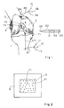
- FIG 1 very schematically shows a tibia 1 and a femur 2.
- the femur includes two condyles 3 and 4 on which is articulated the tibia.
- the destroyed ligament to replace must be located between a tibial attachment point T1 and a point F1 femoral attachment.
- T1 attachment point can be determined a priori by the surgeon from an observation, while with regard to the femoral attachment point, we only know that it must be in an area A which is a portion of the throat surface trochlean.
- One of the elements of the present invention resides in the application of such systems to the problem posed.
- a first set or triplet 10 of photoemitters 11, 12, 13 is fixed to the tibia at a point 14, for example by screwing.
- a pointer 20 provided with photoemitters 21, 22 and 23 interacting with the detection system to determine with precision any position taken by its tip 24. This pointer is used to point to point T1. It is then possible by a conventional computer system to determine the vector VT1 connecting point 14 to point T1 and therefore locating the point T1 for any position of the tibia.
- a second triplet 30 of photoemitters comprising for example three photodiodes 31, 32, 33, fixed to the femur at a point 34.
- the triplet 30 can be located by the detector system in the same way as triplet 10 and the vector VFi between point 34 and each of the points Fi can be calculated. Thus, the points Fi are located even if the femur moves.
- the present invention also provides for performing an intervention at the point F1 previously determined, this intervention being located exactly at point F1.
- the present invention provides an intervention tool, by example a drill, also carrying light emitting elements to ensure the positioning of its point of action.
- the photoemitters can be provided either on the tool itself or on a tool guide or even on an instrument visually fixing the position of the intervention point desired, for example a laser illuminating the point F1. So by example, a surgeon may first position a guide desired way then drive in a drill or from the point F1 towards the inside or from the outside of the condyle towards point F1 to create a tunnel leading to point F1. Then, as indicated above, a natural tendon or artificial can be placed in the tunnel thus formed.
- the present invention is susceptible of numerous variants and modifications which will appear to those skilled in the art.
- it can be applied as indicated previously to other areas than the positioning of a tendon tibio-femoral cross.
- we previously planned a process for selecting a point of an organ such as its distance remains invariant with respect to a point of another body movable relative to the first.
- the selected point may, in other applications, be chosen according to any other criteria.
Description
- est fréquente : plusieurs milliers de cas par an en France, ce en raison de l'importance de la gêne fonctionnelle induite par la rupture du ligament croisé antérieur, rupture fréquente car consécutive à des accidents survenant lors de la pratique de sports de masse (ski, football, hand-ball, volley ball...),
- a pour ambition de réduire le pourcentage d'évolution arthrosique de ces genoux traumatisés ; on admet qu'avec les techniques actuelles de plastie ligamentaire, 50 % de ces genoux traumatisés, opérés ou non, poseront, 25 ans après le traumatisme, le problème d'une prothèse totale de genou.
Claims (9)
- Procédé de détermination de la position d'un point d'un deuxième organe mobile par rapport à un premier organe tel que la distance entre ce point du deuxième organe et un point déterminé du premier organe soit sensiblement invariante lors du déplacement du premier organe par rapport au deuxième, ce procédé faisant usage d'un système de repérage tridimensionnel de triplets d'éléments émetteurs comprenant notamment un pointeur repérable par ce système, caractérisé en ce qu'il comprend les étapes suivantes :lier un premier triplet (14) au premier organe ;pointer avec le pointeur (20) la position du point déterminé (T1) du premier organe et repérer cette position par rapport à celle du premier triplet ;pointer avec le pointeur les positions d'un ensemble de deuxièmes points (Fi) situés dans une zone (A) du deuxième organe où est susceptible de se trouver le point invariant ;calculer les distanoes (Di) entre le premier point et chacun des deuxièmes points ;déplacer le deuxième organe par rapport au premier et calculer les variations desdites distances ; etsélectionner parmi les deuxièmes points celui (F1) pour lequel ladite distance est sensiblement invariante.
- Procédé selon la revendication 1, caractérisé en ce qu'il comprend en outre les étapes consistant à lier un deuxième triplet (30) au deuxième organe et à repérer les positions des deuxièmes points par rapport à ce deuxième triplet.
- Procédé selon la revendication 1, caractérisé en ce qu'il comprend l'étape consistant à afficher sur un écran (E) les projections sur un plan des deuxièmes points.
- Procédé selon l'une quelconque des revendications 1 à 3, caractérisé en ce que le premier organe est un tibia (1) et le deuxième organe est un fémur (2), le point déterminé (T1) du tibia étant un premier point d'attache d'un ligament croisé du genou et le point invariant (F1) du deuxième organe étant le point d'attache fémoral de ce ligament croisé.
- Procédé selon la revendication 1, caractérisé en ce que le système de repérage tridimensionnel est un système à photodiodes et caméras.
- Application du procédé selon l'une quelconque des revendications 1 à 5, au positionnement d'un outil sur le point invariant, caractérisé en ce qu'il consiste à munir l'outil ou un support de guidage de cet outil d'un triplet d'éléments émetteurs et à positionner l'outil ou son support pour que le point d'action de l'outil passe par ledit point invariant.
- Application du procédé selon les revendications 4 et 6 à la réalisation d'un perçage passant par le point invariant du deuxième ensemble de points, caractérisé en ce qu'il consiste à munir un support de guidage d'un outil de perçage d'un triplet d'éléments émetteur et à positionner ce support pour que l'axe de perçage passe par le point invariant.
- Système de détermination de la position d'un point d'un deuxième organe mobile par rapport à un premier organe tel que la distance entre ce point du deuxième organe et un point déterminé du premier organe suive une loi prédéterminée lors du déplacement du premier organe par rapport au deuxième, ce système comprenant des moyens de repérage tridimensionnel de triplets d'éléments émetteurs et d'un pointeur, caractérisé en ce qu'il comprend :un premier triplet (14) fixé au premier organe ;un pointeur (20) pour pointer la position du point déterminé (T1) du premier organe et les positions d'un ensemble de deuxièmes points (Fi) situés dans la zone du deuxième organe où est susceptible de se trouver le point recherché ; etdes moyens de calcul de la position du point déterminé par rapport à celle du premier triplet, des distances (Di) entre le premier point et chacun des deuxièmes points, et des variations desdites distances quand le deuxième organe se déplace par rapport au premier ;d'où il résulte que l'on peut sélectionner parmi des deuxièmes points celui (F1) pour lequel ladite distance suit ladite loi prédéterminée.
- Système selon la revendication 8, caractérisé en ce qu'il comprend en outre un deuxième triplet (30) lié au deuxième organe et des moyens de calcul des positions des deuxièmes points par rapport à ce deuxième triplet.
Applications Claiming Priority (2)
| Application Number | Priority Date | Filing Date | Title |
|---|---|---|---|
| FR9215549 | 1992-12-15 | ||
| FR9215549A FR2699271B1 (fr) | 1992-12-15 | 1992-12-15 | Procédé de détermination du point d'ancrage fémoral d'un ligament croisé de genou. |
Publications (2)
| Publication Number | Publication Date |
|---|---|
| EP0603089A1 EP0603089A1 (fr) | 1994-06-22 |
| EP0603089B1 true EP0603089B1 (fr) | 1998-06-17 |
Family
ID=9436979
Family Applications (1)
| Application Number | Title | Priority Date | Filing Date |
|---|---|---|---|
| EP93420497A Expired - Lifetime EP0603089B1 (fr) | 1992-12-15 | 1993-12-13 | Procédé de détermination du point d'ancrage fémoral d'un ligament croisé de genou |
Country Status (7)
| Country | Link |
|---|---|
| US (1) | US5564437A (fr) |
| EP (1) | EP0603089B1 (fr) |
| JP (1) | JPH07415A (fr) |
| AT (1) | ATE167380T1 (fr) |
| DE (1) | DE69319212T2 (fr) |
| ES (1) | ES2119879T3 (fr) |
| FR (1) | FR2699271B1 (fr) |
Cited By (5)
| Publication number | Priority date | Publication date | Assignee | Title |
|---|---|---|---|---|
| US6236875B1 (en) | 1994-10-07 | 2001-05-22 | Surgical Navigation Technologies | Surgical navigation systems including reference and localization frames |
| US6347240B1 (en) | 1990-10-19 | 2002-02-12 | St. Louis University | System and method for use in displaying images of a body part |
| US6491702B2 (en) | 1992-04-21 | 2002-12-10 | Sofamor Danek Holdings, Inc. | Apparatus and method for photogrammetric surgical localization |
| US6725082B2 (en) | 1999-03-17 | 2004-04-20 | Synthes U.S.A. | System and method for ligament graft placement |
| US8046053B2 (en) | 1994-10-07 | 2011-10-25 | Foley Kevin T | System and method for modifying images of a body part |
Families Citing this family (62)
| Publication number | Priority date | Publication date | Assignee | Title |
|---|---|---|---|---|
| JP2617965B2 (ja) * | 1988-01-20 | 1997-06-11 | オリンパス光学工業株式会社 | 一眼レフレックスカメラのファインダー光学系 |
| US5571083A (en) * | 1994-02-18 | 1996-11-05 | Lemelson; Jerome H. | Method and system for cell transplantation |
| DE4446934C1 (de) * | 1994-12-28 | 1996-07-04 | Basim A Dr Med Fleega | Medizinischer Meßstab zur Verwendung bei operativen transarthroskopischen Eingriffen |
| US5806518A (en) * | 1995-09-11 | 1998-09-15 | Integrated Surgical Systems | Method and system for positioning surgical robot |
| US8480754B2 (en) | 2001-05-25 | 2013-07-09 | Conformis, Inc. | Patient-adapted and improved articular implants, designs and related guide tools |
| US8882847B2 (en) | 2001-05-25 | 2014-11-11 | Conformis, Inc. | Patient selectable knee joint arthroplasty devices |
| US8735773B2 (en) | 2007-02-14 | 2014-05-27 | Conformis, Inc. | Implant device and method for manufacture |
| US8556983B2 (en) | 2001-05-25 | 2013-10-15 | Conformis, Inc. | Patient-adapted and improved orthopedic implants, designs and related tools |
| US8545569B2 (en) | 2001-05-25 | 2013-10-01 | Conformis, Inc. | Patient selectable knee arthroplasty devices |
| US9603711B2 (en) | 2001-05-25 | 2017-03-28 | Conformis, Inc. | Patient-adapted and improved articular implants, designs and related guide tools |
| US20040133276A1 (en) | 2002-10-07 | 2004-07-08 | Imaging Therapeutics, Inc. | Minimally invasive joint implant with 3-Dimensional geometry matching the articular surfaces |
| US7468075B2 (en) | 2001-05-25 | 2008-12-23 | Conformis, Inc. | Methods and compositions for articular repair |
| US8771365B2 (en) | 2009-02-25 | 2014-07-08 | Conformis, Inc. | Patient-adapted and improved orthopedic implants, designs, and related tools |
| DE29704393U1 (de) * | 1997-03-11 | 1997-07-17 | Aesculap Ag | Vorrichtung zur präoperativen Bestimmung der Positionsdaten von Endoprothesenteilen |
| DE19747427C2 (de) * | 1997-10-28 | 1999-12-09 | Zeiss Carl Fa | Vorrichtung zur Knochensegmentnavigation |
| WO1999023956A1 (fr) * | 1997-11-05 | 1999-05-20 | Synthes Ag, Chur | Representation virtuelle d'un os ou d'une articulation |
| US6021343A (en) * | 1997-11-20 | 2000-02-01 | Surgical Navigation Technologies | Image guided awl/tap/screwdriver |
| ES2228043T3 (es) * | 1998-05-28 | 2005-04-01 | Orthosoft, Inc. | Sistema quirurgico interactivo asistido por ordenador. |
| US6033415A (en) * | 1998-09-14 | 2000-03-07 | Integrated Surgical Systems | System and method for performing image directed robotic orthopaedic procedures without a fiducial reference system |
| US7239908B1 (en) | 1998-09-14 | 2007-07-03 | The Board Of Trustees Of The Leland Stanford Junior University | Assessing the condition of a joint and devising treatment |
| JP2002532126A (ja) | 1998-09-14 | 2002-10-02 | スタンフォード ユニバーシティ | 関節状態の評価及び損傷防止装置 |
| FR2785517B1 (fr) * | 1998-11-10 | 2001-03-09 | Univ Joseph Fourier | Procede et dispositif de determination du centre d'une articulation |
| US6430434B1 (en) | 1998-12-14 | 2002-08-06 | Integrated Surgical Systems, Inc. | Method for determining the location and orientation of a bone for computer-assisted orthopedic procedures using intraoperatively attached markers |
| US6322567B1 (en) | 1998-12-14 | 2001-11-27 | Integrated Surgical Systems, Inc. | Bone motion tracking system |
| AU3357400A (en) * | 1999-02-16 | 2000-09-04 | Frederic Picard | Optimizing alignment of an appendicular |
| WO2002022014A1 (fr) | 2000-09-14 | 2002-03-21 | The Board Of Trustees Of The Leland Stanford Junior University | Évaluation de l'état d'une articulation et traitement afférent |
| WO2002023483A2 (fr) | 2000-09-14 | 2002-03-21 | Leland Stanford Junior University | Technique servant a manipuler des images medicales |
| CA2425089A1 (fr) | 2000-09-14 | 2002-03-21 | Philipp Lang | Evaluation de l'etat d'une articulation et d'une perte de cartilage |
| FR2816200A1 (fr) * | 2000-11-06 | 2002-05-10 | Praxim | Determination de la position d'une prothese du genou |
| WO2002096268A2 (fr) | 2001-05-25 | 2002-12-05 | Imaging Therapeutics, Inc. | Methodes et compositions d'arthroplastie |
| AU2003201572A1 (en) * | 2002-01-16 | 2003-09-02 | Orthosoft Inc. | Method and apparatus for reconstructing bone surfaces during surgery |
| US7715602B2 (en) * | 2002-01-18 | 2010-05-11 | Orthosoft Inc. | Method and apparatus for reconstructing bone surfaces during surgery |
| US7166114B2 (en) * | 2002-09-18 | 2007-01-23 | Stryker Leibinger Gmbh & Co Kg | Method and system for calibrating a surgical tool and adapter thereof |
| WO2004032780A1 (fr) * | 2002-09-27 | 2004-04-22 | Aesculap Ag & Co. Kg | Procede et dispositif pour determiner la position du point de sortie tibial du ligament croise avant |
| EP3075356B1 (fr) | 2002-11-07 | 2023-07-05 | ConforMIS, Inc. | Méthode de sélection d'un implant méniscal |
| US7319897B2 (en) * | 2002-12-02 | 2008-01-15 | Aesculap Ag & Co. Kg | Localization device display method and apparatus |
| US7209776B2 (en) * | 2002-12-03 | 2007-04-24 | Aesculap Ag & Co. Kg | Method of determining the position of the articular point of a joint |
| US7427272B2 (en) * | 2003-07-15 | 2008-09-23 | Orthosoft Inc. | Method for locating the mechanical axis of a femur |
| US7905924B2 (en) * | 2003-09-03 | 2011-03-15 | Ralph Richard White | Extracapsular surgical procedure |
| US7873400B2 (en) * | 2003-12-10 | 2011-01-18 | Stryker Leibinger Gmbh & Co. Kg. | Adapter for surgical navigation trackers |
| US7771436B2 (en) * | 2003-12-10 | 2010-08-10 | Stryker Leibinger Gmbh & Co. Kg. | Surgical navigation tracker, system and method |
| US20060036397A1 (en) * | 2004-03-24 | 2006-02-16 | Robert Dick | Method and device for ascertaining a position of a characteristic point |
| EP1579803A1 (fr) * | 2004-03-24 | 2005-09-28 | BrainLAB AG | Méthode et appareil pour détecter la position d'un point caractéristique |
| US7623250B2 (en) * | 2005-02-04 | 2009-11-24 | Stryker Leibinger Gmbh & Co. Kg. | Enhanced shape characterization device and method |
| US20070239169A1 (en) * | 2006-03-17 | 2007-10-11 | Perception Raisonnement Action En Medecine | Reference marker and use in a motion tracking system |
| US8337508B2 (en) | 2006-03-20 | 2012-12-25 | Perception Raisonnement Action En Medecine | Distractor system |
| US7949386B2 (en) | 2006-03-21 | 2011-05-24 | A2 Surgical | Computer-aided osteoplasty surgery system |
| US8214016B2 (en) | 2006-12-12 | 2012-07-03 | Perception Raisonnement Action En Medecine | System and method for determining an optimal type and position of an implant |
| EP2591756A1 (fr) | 2007-02-14 | 2013-05-15 | Conformis, Inc. | Dispositif d'implant et procédé de fabrication |
| US7678147B2 (en) * | 2007-05-01 | 2010-03-16 | Moximed, Inc. | Extra-articular implantable mechanical energy absorbing systems and implantation method |
| US8894714B2 (en) | 2007-05-01 | 2014-11-25 | Moximed, Inc. | Unlinked implantable knee unloading device |
| EP2194836B1 (fr) * | 2007-09-25 | 2015-11-04 | Perception Raisonnement Action En Medecine | Appareil pour aider au diagnostic de l'état du cartilage et procédés thérapeutiques |
| DE502008002604D1 (de) | 2008-02-21 | 2011-03-31 | Brainlab Ag | Lageberechnung von Körperteilen unter Berücksichtigung der anatomischen Symmetrie |
| WO2009111626A2 (fr) | 2008-03-05 | 2009-09-11 | Conformis, Inc. | Implants pour modifier des modèles d’usure de surfaces articulaires |
| JP2011519713A (ja) | 2008-05-12 | 2011-07-14 | コンフォーミス・インコーポレイテッド | 面関節および他の関節の治療のためのデバイスならびに方法 |
| WO2010099231A2 (fr) | 2009-02-24 | 2010-09-02 | Conformis, Inc. | Systèmes automatisés de fabrication d'implants orthopédiques spécifiques au patient et instrumentation |
| AU2010327987B2 (en) | 2009-12-11 | 2015-04-02 | Conformis, Inc. | Patient-specific and patient-engineered orthopedic implants |
| JP2013523415A (ja) | 2010-04-14 | 2013-06-17 | スミス アンド ネフュー インコーポレーテッド | 患者立脚型コンピュータ支援外科的処置のためのシステムおよび方法 |
| CN103476363B (zh) | 2011-02-15 | 2017-06-30 | 康复米斯公司 | 改进的适合患者型关节植入物以及处理、评估、校正、修改和/或适应解剖变化和/或非对称性的手术和工具 |
| US9289264B2 (en) * | 2011-12-29 | 2016-03-22 | Mako Surgical Corp. | Systems and methods for guiding an instrument using haptic object with collapsing geometry |
| US9639156B2 (en) | 2011-12-29 | 2017-05-02 | Mako Surgical Corp. | Systems and methods for selectively activating haptic guide zones |
| KR101705199B1 (ko) * | 2015-05-12 | 2017-02-09 | 주식회사 코어라인소프트 | 의료 영상을 이용한 전방십자인대 재건 수술의 시뮬레이션 시스템 및 방법 |
Family Cites Families (6)
| Publication number | Priority date | Publication date | Assignee | Title |
|---|---|---|---|---|
| CH671873A5 (fr) * | 1985-10-03 | 1989-10-13 | Synthes Ag | |
| US4712542A (en) * | 1986-06-30 | 1987-12-15 | Medmetric Corporation | System for establishing ligament graft orientation and isometry |
| US5037426A (en) * | 1988-09-19 | 1991-08-06 | Marlowe Goble E | Procedure for verifying isometric ligament positioning |
| US4964862A (en) * | 1989-08-31 | 1990-10-23 | Micro Strain Company | Method of and means for measuring ligament tension |
| DE9005819U1 (fr) * | 1990-05-22 | 1990-07-26 | Aesculap Ag, 7200 Tuttlingen, De | |
| US5230623A (en) * | 1991-12-10 | 1993-07-27 | Radionics, Inc. | Operating pointer with interactive computergraphics |
-
1992
- 1992-12-15 FR FR9215549A patent/FR2699271B1/fr not_active Expired - Fee Related
-
1993
- 1993-12-13 EP EP93420497A patent/EP0603089B1/fr not_active Expired - Lifetime
- 1993-12-13 DE DE69319212T patent/DE69319212T2/de not_active Expired - Lifetime
- 1993-12-13 ES ES93420497T patent/ES2119879T3/es not_active Expired - Lifetime
- 1993-12-13 AT AT93420497T patent/ATE167380T1/de active
- 1993-12-14 US US08/166,032 patent/US5564437A/en not_active Expired - Lifetime
- 1993-12-15 JP JP5342219A patent/JPH07415A/ja not_active Withdrawn
Cited By (7)
| Publication number | Priority date | Publication date | Assignee | Title |
|---|---|---|---|---|
| US6347240B1 (en) | 1990-10-19 | 2002-02-12 | St. Louis University | System and method for use in displaying images of a body part |
| US6434415B1 (en) | 1990-10-19 | 2002-08-13 | St. Louis University | System for use in displaying images of a body part |
| US6490467B1 (en) | 1990-10-19 | 2002-12-03 | Surgical Navigation Technologies, Inc. | Surgical navigation systems including reference and localization frames |
| US6491702B2 (en) | 1992-04-21 | 2002-12-10 | Sofamor Danek Holdings, Inc. | Apparatus and method for photogrammetric surgical localization |
| US6236875B1 (en) | 1994-10-07 | 2001-05-22 | Surgical Navigation Technologies | Surgical navigation systems including reference and localization frames |
| US8046053B2 (en) | 1994-10-07 | 2011-10-25 | Foley Kevin T | System and method for modifying images of a body part |
| US6725082B2 (en) | 1999-03-17 | 2004-04-20 | Synthes U.S.A. | System and method for ligament graft placement |
Also Published As
| Publication number | Publication date |
|---|---|
| ES2119879T3 (es) | 1998-10-16 |
| EP0603089A1 (fr) | 1994-06-22 |
| ATE167380T1 (de) | 1998-07-15 |
| DE69319212T2 (de) | 1998-11-19 |
| US5564437A (en) | 1996-10-15 |
| FR2699271B1 (fr) | 1995-03-17 |
| DE69319212D1 (de) | 1998-07-23 |
| JPH07415A (ja) | 1995-01-06 |
| FR2699271A1 (fr) | 1994-06-17 |
Similar Documents
| Publication | Publication Date | Title |
|---|---|---|
| EP0603089B1 (fr) | Procédé de détermination du point d'ancrage fémoral d'un ligament croisé de genou | |
| EP1341468A1 (fr) | Systeme de determination de la position d'une prothese du genou | |
| US11617492B2 (en) | Medical three-dimensional (3D) scanning and mapping system | |
| EP0187283B1 (fr) | Appareil pour repérer in situ les trous transversaux d'une broche creuse implantée dans le canal médullaire, pour la contention des fragments d'un os fracturé | |
| EP1712192A1 (fr) | Dispositif chirurgical d'implantation d'une prothèse partielle ou totale de genou | |
| EP1732448B1 (fr) | Ensemble d ancillaires pour implanter une prothese de genou | |
| US20200100916A1 (en) | Method of using a measuring instrument in an orthopaedic surgical procedure | |
| JP2001522630A (ja) | 骨または骨関節の仮想表示 | |
| FR2831794A1 (fr) | Procede de selection d'elements de prothese de genou et dispositif pour sa mise en oeuvre | |
| FR2918554A1 (fr) | Viseur ou guide de percage pour ligamentoplastie. | |
| EP0733338A1 (fr) | Dispositif de mesure de la position du point de fixation d'un oeil sur une cible | |
| EP1059061A3 (fr) | Appareil et méthode de mesure des propriétés refractives de l'oeil humain | |
| EP1083840A1 (fr) | Procede et appareil de mise en correspondance pour la chirurgie robotisee | |
| AU2005200970A1 (en) | Navigated stemmed orthopaedic implant inserter | |
| FR3052654A1 (fr) | Procede d'estimation de l'orientation relative entre tibia et femur | |
| FR3030222A1 (fr) | Systeme d'orientation chirurgical | |
| EP4230168A1 (fr) | Système de chirurgie rachidienne robotisée | |
| US11944393B2 (en) | Patella tracking | |
| FR2882248A1 (fr) | Porcede et systeme pour aider au guidage d'un outil a usage medical | |
| FR2801185A1 (fr) | Video endoscope securise a profilometre laser integre pour la chirurgie assistee par ordinateur | |
| FR3078624A1 (fr) | Systeme et procede d’assistance en realite augmentee au positionnement d’une instrumentation chirurgicale specifique a un patient | |
| EP4069130A1 (fr) | Systeme de guidage en realite augmentee d'une operation chirurgicale d'une partie d'articulation d'un os | |
| EP0868886A1 (fr) | Procédé et dispositif de marquage et de repérage d'une zone à traiter dans un organisme | |
| EP3880087A1 (fr) | Dispositif de coupe pour la pose d'une prothése de genou | |
| FR2838627A1 (fr) | Ancillaire pour chirurgie orthopedique sous systeme de navigation |
Legal Events
| Date | Code | Title | Description |
|---|---|---|---|
| PUAI | Public reference made under article 153(3) epc to a published international application that has entered the european phase |
Free format text: ORIGINAL CODE: 0009012 |
|
| AK | Designated contracting states |
Kind code of ref document: A1 Designated state(s): AT BE CH DE ES FR GB IT LI NL |
|
| 17P | Request for examination filed |
Effective date: 19941130 |
|
| GRAG | Despatch of communication of intention to grant |
Free format text: ORIGINAL CODE: EPIDOS AGRA |
|
| 17Q | First examination report despatched |
Effective date: 19970821 |
|
| GRAG | Despatch of communication of intention to grant |
Free format text: ORIGINAL CODE: EPIDOS AGRA |
|
| GRAH | Despatch of communication of intention to grant a patent |
Free format text: ORIGINAL CODE: EPIDOS IGRA |
|
| GRAH | Despatch of communication of intention to grant a patent |
Free format text: ORIGINAL CODE: EPIDOS IGRA |
|
| GRAA | (expected) grant |
Free format text: ORIGINAL CODE: 0009210 |
|
| AK | Designated contracting states |
Kind code of ref document: B1 Designated state(s): AT BE CH DE ES FR GB IT LI NL |
|
| REF | Corresponds to: |
Ref document number: 167380 Country of ref document: AT Date of ref document: 19980715 Kind code of ref document: T |
|
| RIN1 | Information on inventor provided before grant (corrected) |
Inventor name: CHAMPLEBAUX, GUILLAUME Inventor name: LAVALLEE, STEPHANE Inventor name: TROCCAZ, JOCELYNE Inventor name: JULLIARD, REMI Inventor name: CINQUIN, PHILIPPE Inventor name: BAINVILLE, ERIC |
|
| REG | Reference to a national code |
Ref country code: CH Ref legal event code: EP |
|
| REF | Corresponds to: |
Ref document number: 69319212 Country of ref document: DE Date of ref document: 19980723 |
|
| GBT | Gb: translation of ep patent filed (gb section 77(6)(a)/1977) |
Effective date: 19980804 |
|
| REG | Reference to a national code |
Ref country code: CH Ref legal event code: NV Representative=s name: MOINAS SAVOYE & CRONIN |
|
| REG | Reference to a national code |
Ref country code: ES Ref legal event code: FG2A Ref document number: 2119879 Country of ref document: ES Kind code of ref document: T3 |
|
| PLBE | No opposition filed within time limit |
Free format text: ORIGINAL CODE: 0009261 |
|
| STAA | Information on the status of an ep patent application or granted ep patent |
Free format text: STATUS: NO OPPOSITION FILED WITHIN TIME LIMIT |
|
| 26N | No opposition filed | ||
| REG | Reference to a national code |
Ref country code: GB Ref legal event code: IF02 |
|
| PGFP | Annual fee paid to national office [announced via postgrant information from national office to epo] |
Ref country code: DE Payment date: 20121207 Year of fee payment: 20 Ref country code: CH Payment date: 20121211 Year of fee payment: 20 |
|
| PGFP | Annual fee paid to national office [announced via postgrant information from national office to epo] |
Ref country code: ES Payment date: 20121219 Year of fee payment: 20 Ref country code: IT Payment date: 20121217 Year of fee payment: 20 Ref country code: GB Payment date: 20121219 Year of fee payment: 20 |
|
| PGFP | Annual fee paid to national office [announced via postgrant information from national office to epo] |
Ref country code: AT Payment date: 20121123 Year of fee payment: 20 Ref country code: NL Payment date: 20121122 Year of fee payment: 20 |
|
| PGFP | Annual fee paid to national office [announced via postgrant information from national office to epo] |
Ref country code: FR Payment date: 20130129 Year of fee payment: 20 Ref country code: BE Payment date: 20121219 Year of fee payment: 20 |
|
| REG | Reference to a national code |
Ref country code: DE Ref legal event code: R071 Ref document number: 69319212 Country of ref document: DE |
|
| REG | Reference to a national code |
Ref country code: NL Ref legal event code: V4 Effective date: 20131213 |
|
| BE20 | Be: patent expired |
Owner name: UNIVERSITE JOSEPH *FOURIER Effective date: 20131213 |
|
| REG | Reference to a national code |
Ref country code: CH Ref legal event code: PL |
|
| REG | Reference to a national code |
Ref country code: GB Ref legal event code: PE20 Expiry date: 20131212 |
|
| PG25 | Lapsed in a contracting state [announced via postgrant information from national office to epo] |
Ref country code: DE Free format text: LAPSE BECAUSE OF EXPIRATION OF PROTECTION Effective date: 20131214 Ref country code: GB Free format text: LAPSE BECAUSE OF EXPIRATION OF PROTECTION Effective date: 20131212 |
|
| REG | Reference to a national code |
Ref country code: AT Ref legal event code: MK07 Ref document number: 167380 Country of ref document: AT Kind code of ref document: T Effective date: 20131213 |
|
| REG | Reference to a national code |
Ref country code: ES Ref legal event code: FD2A Effective date: 20140925 |
|
| PG25 | Lapsed in a contracting state [announced via postgrant information from national office to epo] |
Ref country code: ES Free format text: LAPSE BECAUSE OF EXPIRATION OF PROTECTION Effective date: 20131214 |