EP0601820B1 - Mobiles Funkgerät mit Vorrichtung zur Leistungsregelung - Google Patents
Mobiles Funkgerät mit Vorrichtung zur Leistungsregelung Download PDFInfo
- Publication number
- EP0601820B1 EP0601820B1 EP93309777A EP93309777A EP0601820B1 EP 0601820 B1 EP0601820 B1 EP 0601820B1 EP 93309777 A EP93309777 A EP 93309777A EP 93309777 A EP93309777 A EP 93309777A EP 0601820 B1 EP0601820 B1 EP 0601820B1
- Authority
- EP
- European Patent Office
- Prior art keywords
- pager
- unit
- mobile radio
- line terminal
- radio apparatus
- Prior art date
- Legal status (The legal status is an assumption and is not a legal conclusion. Google has not performed a legal analysis and makes no representation as to the accuracy of the status listed.)
- Expired - Lifetime
Links
Images


Classifications
-
- H—ELECTRICITY
- H04—ELECTRIC COMMUNICATION TECHNIQUE
- H04W—WIRELESS COMMUNICATION NETWORKS
- H04W52/00—Power management, e.g. TPC [Transmission Power Control], power saving or power classes
- H04W52/02—Power saving arrangements
- H04W52/0209—Power saving arrangements in terminal devices
- H04W52/0225—Power saving arrangements in terminal devices using monitoring of external events, e.g. the presence of a signal
- H04W52/0229—Power saving arrangements in terminal devices using monitoring of external events, e.g. the presence of a signal where the received signal is a wanted signal
-
- H—ELECTRICITY
- H04—ELECTRIC COMMUNICATION TECHNIQUE
- H04W—WIRELESS COMMUNICATION NETWORKS
- H04W52/00—Power management, e.g. TPC [Transmission Power Control], power saving or power classes
- H04W52/02—Power saving arrangements
- H04W52/0209—Power saving arrangements in terminal devices
- H04W52/0261—Power saving arrangements in terminal devices managing power supply demand, e.g. depending on battery level
- H04W52/0296—Power saving arrangements in terminal devices managing power supply demand, e.g. depending on battery level switching to a backup power supply
-
- Y—GENERAL TAGGING OF NEW TECHNOLOGICAL DEVELOPMENTS; GENERAL TAGGING OF CROSS-SECTIONAL TECHNOLOGIES SPANNING OVER SEVERAL SECTIONS OF THE IPC; TECHNICAL SUBJECTS COVERED BY FORMER USPC CROSS-REFERENCE ART COLLECTIONS [XRACs] AND DIGESTS
- Y02—TECHNOLOGIES OR APPLICATIONS FOR MITIGATION OR ADAPTATION AGAINST CLIMATE CHANGE
- Y02D—CLIMATE CHANGE MITIGATION TECHNOLOGIES IN INFORMATION AND COMMUNICATION TECHNOLOGIES [ICT], I.E. INFORMATION AND COMMUNICATION TECHNOLOGIES AIMING AT THE REDUCTION OF THEIR OWN ENERGY USE
- Y02D30/00—Reducing energy consumption in communication networks
- Y02D30/70—Reducing energy consumption in communication networks in wireless communication networks
Definitions
- the present invention relates to a mobile radio apparatus for a portable telephone and the like which is desired to be operated with low power consumption.
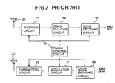
- Fig. 7 is a schematic diagram illustrating a conventional mobile radio apparatus.
- a portable telephone is shown.
- reference numerals 21 and 22 denote antennas.
- the antenna 21 is a receiving antenna, while the antenna 22 is operated as a transmitting antenna upon transmission and is operated as a receiving antenna upon reception to perform the diversity reception together with the antenna 21.
- Numeral 23 denotes a receiving circuit for amplifying a received signal.
- Numeral 24 denotes a demodulation circuit which demodulates a baseband signal from the received signal to obtain a digital data and reproduces a clock from the received signal.
- Numeral 25 denotes a voice decoding circuit which converts the digital data into an analog voice signal.
- Numeral 26 denotes a voice encoding circuit for converting the analog voice signal into a digital data.
- Numeral 27 denotes a modulation circuit for performing modulation in accordance with modulation systems by using the digital data.
- Numeral 28 denotes a transmitting circuit for amplifying a modulated signal.
- Numeral 30 denotes a timing control circuit for controlling the timing for the whole mobile radio apparatus.
- the position registration is required for recognizing a position of the mobile radio apparatus to a base station of a portable telephone network for the changed simultaneous calling area and transmission is made for the position registration.
- the transmission is made only upon the position registration operation, while it is necessary to reduce the power consumption at this time as small as possible.
- the intermittent receiving operation is performed to lengthen the time capable of waiting for reception for one charging of the battery, while the waitable time is only about several ten hours and the charging of the battery is required frequently.
- the mobile radio apparatus including a pager combined with the portable telephone is disclosed in JP-A-61-67336 and JP-A-5-102924.
- the pager unit is operated during the waiting for reception and the portable telephone is supplied with power after a calling signal has been received, so that reduction of the power consumption during the waiting for reception is effected.
- JP 405 7592 dicloses a radio telephone system which saves power consumption by utilising a function of a paging system so as to apply a power supply for a radio telephone set automatically thereby interrupting the power supply when no call is estimated.
- An object of the present invention is to provide a mobile radio apparatus in which a power supply of a portable telephone unit is off and only a pager unit is operated during waiting for reception while a power supply of the pager unit is off and only the portable telephone unit is operated at need to minimize the power consumption.
- Power supply and selector means for supplying electric power to one of said radio-telephone line terminal unit and said pager unit ;
- the power supply of the radio-telephone line terminal unit is off in the waiting state and the frequency of transmission for the position registration necessary for the radio-telephone line terminal unit is reduced remarkably, the power consumption of the mobile radio apparatus is reduced greatly.
- Fig. 1 schematically illustrating a mobile radio apparatus according to a first embodiment of the present invention.
- numeral 1 denotes a mobile radio apparatus
- 2 a radio-telephone line terminal unit (hereinafter referred to as a line terminal unit 2 in description of the embodiment), 3 a pager unit, and 4 a power supply control unit for controlling turning-on-and-off of power supplies for the line terminal unit 2 and the pager unit 3.
- the mobile radio apparatus 1 comprises the line terminal unit 2, the pager unit 3 and the power supply control unit 4.
- the line terminal unit 2 is described as a portable telephone as an example, however, the line terminal unit 2 may be a terminal unit of other kinds capable of being connected to a radio-telephone line, such as, for example, a picture communication terminal unit and a data communication terminal unit.
- the line terminal unit 2 includes blocks designated by reference numerals 21 to 29.
- the blocks designated by reference numerals 21 to 28 are the same blocks as those constituting the conventional mobile radio apparatus shown in Fig. 7 and accordingly description thereof is omitted by designating them by the same reference numerals.
- Reference numeral 29 denotes a timing control circuit for controlling the timing for the blocks of the line terminal unit 2.
- the timing control unit 29 is different from the timing control unit 30 of Fig.
- the pager unit 3 includes elements designated by reference numerals 31 to 34.
- Reference numeral 31 denotes an antenna of the pager unit for receiving electric wave for the pager unit and which is provided separately from the antennas 21 and 22 of the line terminal unit 2.
- Numeral 32 denotes a pager receiving circuit for amplifying a pager signal received by the pager antenna 31.
- Numeral 33 denotes a pager demodulation circuit for demodulating the pager signal.
- Numeral 34 denotes a pager decoding circuit for decoding the demodulated pager signal to produce an incoming control signal.
- the power supply unit 4 includes elements designated by reference numerals 41 to 43.
- Numeral 41 denotes a power supply control circuit for controlling to supply a supply voltage from a battery (not shown) to any of the line terminal unit 2 and the pager unit 3 in accordance with a control signal.
- Numeral 42 denotes a power supply change-over switch which is controlled by the power supply control circuit 41 to be changed over so that the battery power supply is connected to either the line terminal unit 2 or the pager unit 3.
- Numeral 43 denotes a CPU for controlling operation of each of portions of the mobile radio apparatus 1 in response to signals from the timing control circuit 29, the pager decoding circuit 34 and a power supply switch (not shown) of the mobile radio apparatus 1.
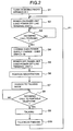
- Fig. 2 is a flow chart showing operation of the first embodiment. Referring now to Figs. 1 and 2, operation of the first embodiment is described.
- the power supply change-over switch 42 is changed over to the side of the pager unit 3 by means of the CPU 43 and the power supply control circuit 41 of the power supply control unit 4 to turn on only the power supply of the pager unit 3 (step S2) so that the intermittent receiving operation of the pager signal is made with the low power consumption by using the pager network which does not require the position registration.
- the CPU 43 When there is an incoming call to the pager unit 3 during waiting for reception (step S3), the CPU 43 receives an incoming control signal from the pager decoding circuit 34 to control the power supply control unit 41 so that the power supply change-over switch 42 is changed over to the side of the line terminal unit 2 (step S4). Consequently, the line terminal unit 2 is powered on and the pager unit 3 is powered off (step S5). Thus, the CPU 43 sends the control signal to the timing control circuit 29 of the line terminal unit 2 to thereby perform the position registration to cause the base station of the portable telephone network of the area to recognize the position of the portable telephone (step S6) and the line terminal unit 2 is moved to the usual talking mode (step S7).
- the calling side or party dials the telephone number of the portable telephone to call it, so that an incoming call arrives at the portable telephone (step S8) to thereby be able to make talking between the calling side and the called portable telephone (step S9).
- the CPU 43 receives the control signal from the timing control circuit 29 (path P1) and changes over the power supply change-over switch 42 to the pager unit 3 again so that the pager unit 3 is powered on and the line terminal unit 2 is powered off to enter the waiting state for reception of the pager signal (step S2).
- Fig. 3 schematically illustrates a mobile radio apparatus according to a second embodiment of the present invention.
- a timer 44 is added to the power supply control unit 4 and performs timing control by means of the CPU 43.
- elements except for the timer 44 are those having the same functions as in the first embodiment and description thereof is omitted by designating them by the same reference numerals.
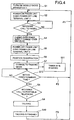
- Fig. 4 is a flow chart showing operation of the second embodiment. Referring now to Figs. 3 and 4, operation of the second embodiment is described.
- the steps S1 to S10 have the same operation as those of the first embodiment shown in Fig. 2 and description thereof is omitted by designating them by the same step numbers.
- the timer 44 of the power supply control unit 4 starts its operation in accordance with the control of the CPU 43 (step S11).
- the CPU 43 monitors the timer 44 (step S12) and when an incoming call arrives at the line terminal unit 2 within a predetermined time period from the start of the operation of the timer 44 (step S8), talking is made (step S9).
- the CPU 43 receives the control signal from the timer 44 and the timing control circuit 29 (path P1) and the power supply change-over switch 42 is changed over to the side of the pager unit 3 again, so that the pager unit 3 is turned on and the line terminal unit 2 is turned off to thereby enter the waiting state for reception of the pager signal (step S2).
- Fig. 5 illustrates a calling procedure of the mobile radio apparatus 1 according to the first and second embodiments.
- Fig. 6 schematically illustrates a configuration of a communication network for the radio-telephone and the pager including the mobile radio apparatus 1 according to the first and second embodiments.
- Letters (A) to (L) shown in Fig. 5 correspond to letters (A) to (L) shown in Fig. 6, respectively.
- reference numeral 61 denotes a fixed telephone, 62 a portable telephone, 63 a base station for the portable telephone, 64 a public telephone network, 65 a base station for a mobile radio apparatus, 66 the mobile radio apparatus, and 67 a base station for a pager.
- the calling side or party calls the mobile radio apparatus 1 through the pager network (process A).
- the pager base station performs the simultaneous calling for the pager (process B).
- the mobile radio apparatus 1 receives an incoming pager signal (process C), and turns on the power supply of the line terminal unit 2 and turn off the power supply of the pager unit 3 (process D) so that the position registration is performed (process E).
- the mobile radio apparatus 1 is moved to the usual talking mode (process F).
- the calling side cuts off the telephone once and performs the calling of the portable telephone (process G).
- the simultaneous calling is performed through the public telephone network as the portable telephone (process H), so that an incoming portable telephone call is received by the mobile radio apparatus 1 (process J). Talking is then made (process K) and when the talking has been finished (process L) and the mobile radio apparatus is moved to the waiting state for reception, the mobile radio apparatus turns off the power supply of the line terminal unit 2 and turns on the power supply of the pager unit 3 again.
- the power supply of the line terminal unit 2 is turned off and only the power supply of the pager unit 3 is turned on during waiting for reception to thereby enter the waiting state for reception for the pager which does not require the position registration.
- the line terminal unit 2 is turned on and the pager unit 3 is turned off to perform the position registration and move to the usual talking mode.
- the calling side first performs the pager calling and then performs the calling of the portable telephone, while one-to-one correspondence of the pager number and the telephone number of the portable telephone can cause the mobile radio apparatus 1 to be automatically moved to the talking mode only by performing the pager calling.
- the mobile radio apparatus comprises the pager unit and the power supply control unit in addition to the radio-telephone line terminal unit and turns off the power supply of the line terminal unit during waiting for reception of the radio-telephone line to wait for reception of an incoming pager signal.
- the power supply control unit turns on the power supply of the line terminal unit and performs the necessary position registration. Accordingly, since it is not necessary to perform the intermittent receiving operation or the transmission for the position registration that is always performed during waiting for reception of the conventional mobile radio apparatus, the power consumption during waiting for reception can be reduced greatly and the time capable of waiting for reception by one charging can be also lengthen greatly so that the usable time of the mobile radio apparatus can be made long.
Landscapes
- Engineering & Computer Science (AREA)
- Computer Networks & Wireless Communication (AREA)
- Signal Processing (AREA)
- Mobile Radio Communication Systems (AREA)
Claims (3)
- Mobilfunkgerät mit:gekennzeichnet durch:einer Funktelefonleitungsanschlußeinheit (2) zum Sprechen mit einer aus einer Mehrzahl Funktelefonbasisstationen entsprechend einer Position des Mobilfunkgeräts und Erzeugen eines ersten Steuersignals, wenn das Sprechen an der Funktelefonleitungsanschlußeinheit beendet ist; undeiner Pagereinheit (3) (Fernrufeinheit) zum Empfangen eines Rufsignals von zumindest einer Pagerbasisstation und Erzeugen eines zweiten Steuersignals, wenn die Pagereinheit (3) ein die Pagereinheit bestimmendes Rufsignal empfängt;eine Leistungsversorgungs- und Auswahleinrichtung (41, 42) zum Zuführen elektrischer Leistung zu entweder der Funktelefonleitungsanschlußeinheit (2) oder der Pagereinheit (3);einer Zeitgebungseinrichtung (44) zur Zeitmessung; undeiner Steuerschaltung (43) zum Steuern der Leistungsversorgungs- und Auswahleinrichtung (41, 42) zum:(i) Zuführen von elektrischer Leistung zu der Pagereinheit (3), wenn das Mobilfunkgerät betätigt ist,(ii) Zuführen von elektrischer Leistung zu der Funktelefonleitungsanschlußeinheit (2), wenn die Steuerschaltung (43) das zweite Steuersignal empfängt, und(iii) wieder Zuführen von elektrischer Leistung zu der Pagereinheit (3), wenn die Steuerschaltung (43) das erste Steuersignal empfängt,und zum Steuem der Zeitgebungseinrichtung (44) zum Starten der Zeitmessung, wenn die Steuerschatung (43) das zweite Steuersignal empfängt, und Steuern der Leistungsversorgungs- und Auswahleinrichtung (41, 42) zum wieder Zuführen von elektrischer Leistung zu der Pagereinheit (3), wenn eine durch ein Ausgangssignal der Zeitgebungseinrichtung (44) dargestellte abgelaufene Zeit eine vorbestimmte Zeitspanne überschreitet, während es kein Eingangssignal für die Funktelefonleitungsanschlußeinheit (2) gibt.
- Mobilfunkgerät nach Anspruch 1, bei dem die Steuerschaltung (43) ausgelegt ist zum Empfangen des zweiten Steuersignals und Senden eines Steuersignals zu der Funktelefonleitungsanschlußeinheit (2), die dazu ausgelegt ist, ansprechend darauf eine Positionsregistrierung zum Rückmelden der Position des Mobilfunkgeräts zu zumindest einer der Funktelefonbasisstationen durchzuführen.
- Mobilfunkgerät nach Anspruch 1 oder 2, bei dem die Pagereinheit (3) die gleiche Telefonnummer hat wie die der Funktelefonleitungsanschlußeinheit (2), wodurch die Pagereinheit (3) gleichzeitig auch gerufen wird, wenn die Funktelefonleitungsanschlußeinheit (2) gerufen wird.
Applications Claiming Priority (2)
| Application Number | Priority Date | Filing Date | Title |
|---|---|---|---|
| JP331520/92 | 1992-12-11 | ||
| JP4331520A JPH06177824A (ja) | 1992-12-11 | 1992-12-11 | 移動無線装置 |
Publications (2)
| Publication Number | Publication Date |
|---|---|
| EP0601820A1 EP0601820A1 (de) | 1994-06-15 |
| EP0601820B1 true EP0601820B1 (de) | 1998-08-12 |
Family
ID=18244572
Family Applications (1)
| Application Number | Title | Priority Date | Filing Date |
|---|---|---|---|
| EP93309777A Expired - Lifetime EP0601820B1 (de) | 1992-12-11 | 1993-12-06 | Mobiles Funkgerät mit Vorrichtung zur Leistungsregelung |
Country Status (4)
| Country | Link |
|---|---|
| US (1) | US5438701A (de) |
| EP (1) | EP0601820B1 (de) |
| JP (1) | JPH06177824A (de) |
| DE (1) | DE69320309T2 (de) |
Cited By (1)
| Publication number | Priority date | Publication date | Assignee | Title |
|---|---|---|---|---|
| US9532310B2 (en) | 2008-12-25 | 2016-12-27 | Google Inc. | Receiver state estimation in a duty cycled radio |
Families Citing this family (31)
| Publication number | Priority date | Publication date | Assignee | Title |
|---|---|---|---|---|
| US6009309A (en) * | 1993-05-04 | 1999-12-28 | Motorola, Inc. | Method of operation a combination radiotelephone and paging device and method of operation |
| GB2280086A (en) * | 1993-07-02 | 1995-01-18 | Michael Victor Rodrigues | Implementing power-saving in a microwave communications network |
| WO1995034998A2 (en) * | 1995-06-06 | 1995-12-21 | Peter James Tsakanikas | Communications access system |
| JP3088246B2 (ja) * | 1994-10-05 | 2000-09-18 | 三菱電機株式会社 | 無線通信装置 |
| US5630224A (en) * | 1994-12-29 | 1997-05-13 | Motorola, Inc. | Method and apparatus for avoiding desensitization of a radio frequency receiver |
| US5606728A (en) * | 1995-06-05 | 1997-02-25 | Motorola, Inc. | Method and apparatus for reducing power consumption in a selective call radio |
| JPH0946174A (ja) * | 1995-07-31 | 1997-02-14 | Sharp Corp | フィルタ回路 |
| US5907418A (en) * | 1995-08-09 | 1999-05-25 | Motorola, Inc. | Apparatus for infrared channel and method therefor |
| US5737707A (en) * | 1996-01-11 | 1998-04-07 | At&T Corp. | Pager-controlled wireless radiotelephone |
| US5802470A (en) * | 1996-01-11 | 1998-09-01 | At&T Corp | Automated wireless-call completion using a paging network |
| FI103454B1 (fi) * | 1996-04-01 | 1999-06-30 | Nokia Telecommunications Oy | Matkaviestimen toimintatilojen ohjaus pakettiradiojärjestelmässä |
| US6041242A (en) * | 1996-06-21 | 2000-03-21 | Coulthard; Steve M. | Portable emergency response communications system and method |
| AU4755797A (en) * | 1996-12-30 | 1998-07-31 | Motorola, Inc. | Micropower paging control of communications functions |
| US6201977B1 (en) | 1998-04-24 | 2001-03-13 | Micron Technology, Inc. | Power-saving mode for portable communication devices |
| US6308060B2 (en) | 1998-06-15 | 2001-10-23 | @Track Communications, Inc. | Method and apparatus for providing a communication path using a paging network |
| JP2000031893A (ja) * | 1998-07-13 | 2000-01-28 | Matsushita Electric Ind Co Ltd | 無線通信機内蔵型携帯情報端末装置 |
| JP3716402B2 (ja) * | 1999-02-19 | 2005-11-16 | 富士通株式会社 | スペクトラム拡散通信方法並びにその送信装置及び受信装置 |
| DE50011304D1 (de) * | 1999-12-16 | 2005-11-10 | Infineon Technologies Ag | Elektronisches gerät mit einem betriebsmodus und einem energiesparenden ruhemodus und verfahren zum umschalten zwischen beiden modi |
| FR2822333B1 (fr) * | 2001-03-15 | 2003-07-04 | Cit Alcatel | Procede de configuration de parametres pour une transmission par paquets de donnees |
| US20030107475A1 (en) * | 2001-12-12 | 2003-06-12 | Bautista Edwin Espanola | Receiver for and method of extending battery life |
| EP1479172B1 (de) * | 2002-02-19 | 2009-04-15 | Alcatel Lucent | Telekommunikationsendgerät, verfahren zum senden und empfangen und sendungssystem |
| EP1510023A4 (de) * | 2002-05-14 | 2010-04-14 | Terahop Networks Inc | Lprf-einrichtungs-aufwecken mit drahtlosem tag |
| US7142107B2 (en) | 2004-05-27 | 2006-11-28 | Lawrence Kates | Wireless sensor unit |
| JP4586601B2 (ja) * | 2005-03-25 | 2010-11-24 | パナソニック電工株式会社 | 無線対応型インターホンシステム |
| JP2006270853A (ja) * | 2005-03-25 | 2006-10-05 | Matsushita Electric Works Ltd | 無線対応型インターホンシステム |
| JP4701778B2 (ja) * | 2005-03-25 | 2011-06-15 | パナソニック電工株式会社 | 無線対応型インターホンシステム |
| US20060260218A1 (en) * | 2005-05-18 | 2006-11-23 | Tanguay Andre P | Door jamb adjusting tool |
| US7496060B2 (en) * | 2005-05-20 | 2009-02-24 | Freescale Semiconductor, Inc. | Extending battery life in communication devices having a plurality of receivers |
| EP1905200A1 (de) | 2005-07-01 | 2008-04-02 | Terahop Networks, Inc. | Nichtdeterministisches und deterministisches netzwerk-routing |
| US20090129306A1 (en) | 2007-02-21 | 2009-05-21 | Terahop Networks, Inc. | Wake-up broadcast including network information in common designation ad hoc wireless networking |
| WO2009140669A2 (en) | 2008-05-16 | 2009-11-19 | Terahop Networks, Inc. | Securing, monitoring and tracking shipping containers |
Family Cites Families (5)
| Publication number | Priority date | Publication date | Assignee | Title |
|---|---|---|---|---|
| JPS6167336A (ja) * | 1984-09-11 | 1986-04-07 | Matsushita Electric Ind Co Ltd | 選択呼出受信装置 |
| JPH0773385B2 (ja) * | 1989-04-03 | 1995-08-02 | 三菱電機株式会社 | 移動電話装置 |
| US5117449A (en) * | 1989-11-03 | 1992-05-26 | Motorola, Inc. | Dual receiver apparatus for integrated paging and radiotelephone functions |
| JP2604887B2 (ja) * | 1990-06-27 | 1997-04-30 | 日本電気移動通信株式会社 | 無線電話システム |
| JP2765299B2 (ja) * | 1991-10-09 | 1998-06-11 | 松下電器産業株式会社 | ページング携帯電話機とその制御方法 |
-
1992
- 1992-12-11 JP JP4331520A patent/JPH06177824A/ja active Pending
-
1993
- 1993-12-06 EP EP93309777A patent/EP0601820B1/de not_active Expired - Lifetime
- 1993-12-06 DE DE69320309T patent/DE69320309T2/de not_active Expired - Fee Related
- 1993-12-07 US US08/162,358 patent/US5438701A/en not_active Expired - Fee Related
Cited By (1)
| Publication number | Priority date | Publication date | Assignee | Title |
|---|---|---|---|---|
| US9532310B2 (en) | 2008-12-25 | 2016-12-27 | Google Inc. | Receiver state estimation in a duty cycled radio |
Also Published As
| Publication number | Publication date |
|---|---|
| DE69320309T2 (de) | 1999-02-11 |
| US5438701A (en) | 1995-08-01 |
| DE69320309D1 (de) | 1998-09-17 |
| JPH06177824A (ja) | 1994-06-24 |
| EP0601820A1 (de) | 1994-06-15 |
Similar Documents
| Publication | Publication Date | Title |
|---|---|---|
| EP0601820B1 (de) | Mobiles Funkgerät mit Vorrichtung zur Leistungsregelung | |
| EP0154288B1 (de) | Verfahren zum Senden von Rufauslösesignalen begrenzter Dauer sowie ortsfeste Station und tragbare Einheit unter Anwendung des Verfahrens | |
| JP3095414B2 (ja) | 複数の動作モードを有する携帯通信およびデータ端末 | |
| JPH05268138A (ja) | 携帯電話機 | |
| US4744101A (en) | Cordless telephone system | |
| JP3072741B2 (ja) | 無線電話装置およびその制御方法 | |
| EP0624003B1 (de) | Drahtloses Fernsprechgerät | |
| US5999823A (en) | Cellular cordless telephone | |
| EP0586170B1 (de) | Mobiles Funkkommunikationsgerät | |
| JPH11289278A (ja) | 携帯無線端末装置 | |
| US20030003973A1 (en) | Radio communication apparatus, radio communication system and communication apparatus | |
| EP0363492B1 (de) | Funkübertragungssystem und entsprechendes regelungsverfahren | |
| GB2355152A (en) | Mobile terminal having waiting-after-receiving operation in a plurality of communicaton systems | |
| JPS5912055B2 (ja) | 移動通信方式 | |
| JPH06177811A (ja) | 移動無線装置 | |
| JPH0722271B2 (ja) | 間欠受信方式 | |
| JP2765299B2 (ja) | ページング携帯電話機とその制御方法 | |
| JPS63175530A (ja) | バツテリ−セ−ビングモ−ド切り替え方式 | |
| JPH08116301A (ja) | パーソナル・ハンディ・フォン・システム | |
| JP2700415B2 (ja) | 個別呼出装置付き無線電話機 | |
| JPH09215039A (ja) | 移動通信の圏外待ち受け方法 | |
| JPH04215324A (ja) | 移動無線機の間欠受信方式 | |
| JPH06252798A (ja) | 携帯無線電話 | |
| JPH05308317A (ja) | 無線電話装置 | |
| JPS63160433A (ja) | 無線呼出し方式 |
Legal Events
| Date | Code | Title | Description |
|---|---|---|---|
| PUAI | Public reference made under article 153(3) epc to a published international application that has entered the european phase |
Free format text: ORIGINAL CODE: 0009012 |
|
| AK | Designated contracting states |
Kind code of ref document: A1 Designated state(s): DE FR GB |
|
| 17P | Request for examination filed |
Effective date: 19940702 |
|
| 17Q | First examination report despatched |
Effective date: 19970325 |
|
| GRAG | Despatch of communication of intention to grant |
Free format text: ORIGINAL CODE: EPIDOS AGRA |
|
| GRAG | Despatch of communication of intention to grant |
Free format text: ORIGINAL CODE: EPIDOS AGRA |
|
| GRAH | Despatch of communication of intention to grant a patent |
Free format text: ORIGINAL CODE: EPIDOS IGRA |
|
| GRAH | Despatch of communication of intention to grant a patent |
Free format text: ORIGINAL CODE: EPIDOS IGRA |
|
| GRAA | (expected) grant |
Free format text: ORIGINAL CODE: 0009210 |
|
| AK | Designated contracting states |
Kind code of ref document: B1 Designated state(s): DE FR GB |
|
| REF | Corresponds to: |
Ref document number: 69320309 Country of ref document: DE Date of ref document: 19980917 |
|
| ET | Fr: translation filed | ||
| PLBE | No opposition filed within time limit |
Free format text: ORIGINAL CODE: 0009261 |
|
| STAA | Information on the status of an ep patent application or granted ep patent |
Free format text: STATUS: NO OPPOSITION FILED WITHIN TIME LIMIT |
|
| 26N | No opposition filed | ||
| PGFP | Annual fee paid to national office [announced via postgrant information from national office to epo] |
Ref country code: DE Payment date: 20001129 Year of fee payment: 8 |
|
| PGFP | Annual fee paid to national office [announced via postgrant information from national office to epo] |
Ref country code: GB Payment date: 20001206 Year of fee payment: 8 |
|
| PGFP | Annual fee paid to national office [announced via postgrant information from national office to epo] |
Ref country code: FR Payment date: 20001212 Year of fee payment: 8 |
|
| PG25 | Lapsed in a contracting state [announced via postgrant information from national office to epo] |
Ref country code: GB Free format text: LAPSE BECAUSE OF NON-PAYMENT OF DUE FEES Effective date: 20011206 |
|
| REG | Reference to a national code |
Ref country code: GB Ref legal event code: IF02 |
|
| PG25 | Lapsed in a contracting state [announced via postgrant information from national office to epo] |
Ref country code: DE Free format text: LAPSE BECAUSE OF NON-PAYMENT OF DUE FEES Effective date: 20020702 |
|
| GBPC | Gb: european patent ceased through non-payment of renewal fee |
Effective date: 20011206 |
|
| PG25 | Lapsed in a contracting state [announced via postgrant information from national office to epo] |
Ref country code: FR Free format text: LAPSE BECAUSE OF NON-PAYMENT OF DUE FEES Effective date: 20020830 |
|
| REG | Reference to a national code |
Ref country code: FR Ref legal event code: ST |