EP0600214B2 - Method and apparatus for the continuous manufacturing of a composite pipe having a substantially smooth external wall portion - Google Patents
Method and apparatus for the continuous manufacturing of a composite pipe having a substantially smooth external wall portion Download PDFInfo
- Publication number
- EP0600214B2 EP0600214B2 EP93117224A EP93117224A EP0600214B2 EP 0600214 B2 EP0600214 B2 EP 0600214B2 EP 93117224 A EP93117224 A EP 93117224A EP 93117224 A EP93117224 A EP 93117224A EP 0600214 B2 EP0600214 B2 EP 0600214B2
- Authority
- EP
- European Patent Office
- Prior art keywords
- tube
- spigot
- external
- external tube
- internal
- Prior art date
- Legal status (The legal status is an assumption and is not a legal conclusion. Google has not performed a legal analysis and makes no representation as to the accuracy of the status listed.)
- Expired - Lifetime
Links
Images


Classifications
-
- B—PERFORMING OPERATIONS; TRANSPORTING
- B29—WORKING OF PLASTICS; WORKING OF SUBSTANCES IN A PLASTIC STATE IN GENERAL
- B29D—PRODUCING PARTICULAR ARTICLES FROM PLASTICS OR FROM SUBSTANCES IN A PLASTIC STATE
- B29D99/00—Subject matter not provided for in other groups of this subclass
- B29D99/001—Producing wall or panel-like structures, e.g. for hulls, fuselages, or buildings
- B29D99/0014—Producing wall or panel-like structures, e.g. for hulls, fuselages, or buildings provided with ridges or ribs, e.g. joined ribs
-
- B—PERFORMING OPERATIONS; TRANSPORTING
- B29—WORKING OF PLASTICS; WORKING OF SUBSTANCES IN A PLASTIC STATE IN GENERAL
- B29C—SHAPING OR JOINING OF PLASTICS; SHAPING OF MATERIAL IN A PLASTIC STATE, NOT OTHERWISE PROVIDED FOR; AFTER-TREATMENT OF THE SHAPED PRODUCTS, e.g. REPAIRING
- B29C48/00—Extrusion moulding, i.e. expressing the moulding material through a die or nozzle which imparts the desired form; Apparatus therefor
- B29C48/03—Extrusion moulding, i.e. expressing the moulding material through a die or nozzle which imparts the desired form; Apparatus therefor characterised by the shape of the extruded material at extrusion
- B29C48/09—Articles with cross-sections having partially or fully enclosed cavities, e.g. pipes or channels
- B29C48/11—Articles with cross-sections having partially or fully enclosed cavities, e.g. pipes or channels comprising two or more partially or fully enclosed cavities, e.g. honeycomb-shaped
-
- B—PERFORMING OPERATIONS; TRANSPORTING
- B29—WORKING OF PLASTICS; WORKING OF SUBSTANCES IN A PLASTIC STATE IN GENERAL
- B29C—SHAPING OR JOINING OF PLASTICS; SHAPING OF MATERIAL IN A PLASTIC STATE, NOT OTHERWISE PROVIDED FOR; AFTER-TREATMENT OF THE SHAPED PRODUCTS, e.g. REPAIRING
- B29C48/00—Extrusion moulding, i.e. expressing the moulding material through a die or nozzle which imparts the desired form; Apparatus therefor
- B29C48/03—Extrusion moulding, i.e. expressing the moulding material through a die or nozzle which imparts the desired form; Apparatus therefor characterised by the shape of the extruded material at extrusion
- B29C48/13—Articles with a cross-section varying in the longitudinal direction, e.g. corrugated pipes
-
- B—PERFORMING OPERATIONS; TRANSPORTING
- B29—WORKING OF PLASTICS; WORKING OF SUBSTANCES IN A PLASTIC STATE IN GENERAL
- B29C—SHAPING OR JOINING OF PLASTICS; SHAPING OF MATERIAL IN A PLASTIC STATE, NOT OTHERWISE PROVIDED FOR; AFTER-TREATMENT OF THE SHAPED PRODUCTS, e.g. REPAIRING
- B29C48/00—Extrusion moulding, i.e. expressing the moulding material through a die or nozzle which imparts the desired form; Apparatus therefor
- B29C48/25—Component parts, details or accessories; Auxiliary operations
- B29C48/30—Extrusion nozzles or dies
- B29C48/303—Extrusion nozzles or dies using dies or die parts movable in a closed circuit, e.g. mounted on movable endless support
-
- B—PERFORMING OPERATIONS; TRANSPORTING
- B29—WORKING OF PLASTICS; WORKING OF SUBSTANCES IN A PLASTIC STATE IN GENERAL
- B29C—SHAPING OR JOINING OF PLASTICS; SHAPING OF MATERIAL IN A PLASTIC STATE, NOT OTHERWISE PROVIDED FOR; AFTER-TREATMENT OF THE SHAPED PRODUCTS, e.g. REPAIRING
- B29C49/00—Blow-moulding, i.e. blowing a preform or parison to a desired shape within a mould; Apparatus therefor
- B29C49/0015—Making articles of indefinite length, e.g. corrugated tubes
- B29C49/0021—Making articles of indefinite length, e.g. corrugated tubes using moulds or mould parts movable in a closed path, e.g. mounted on movable endless supports
-
- B—PERFORMING OPERATIONS; TRANSPORTING
- B29—WORKING OF PLASTICS; WORKING OF SUBSTANCES IN A PLASTIC STATE IN GENERAL
- B29C—SHAPING OR JOINING OF PLASTICS; SHAPING OF MATERIAL IN A PLASTIC STATE, NOT OTHERWISE PROVIDED FOR; AFTER-TREATMENT OF THE SHAPED PRODUCTS, e.g. REPAIRING
- B29C2791/00—Shaping characteristics in general
- B29C2791/004—Shaping under special conditions
- B29C2791/006—Using vacuum
-
- B—PERFORMING OPERATIONS; TRANSPORTING
- B29—WORKING OF PLASTICS; WORKING OF SUBSTANCES IN A PLASTIC STATE IN GENERAL
- B29C—SHAPING OR JOINING OF PLASTICS; SHAPING OF MATERIAL IN A PLASTIC STATE, NOT OTHERWISE PROVIDED FOR; AFTER-TREATMENT OF THE SHAPED PRODUCTS, e.g. REPAIRING
- B29C48/00—Extrusion moulding, i.e. expressing the moulding material through a die or nozzle which imparts the desired form; Apparatus therefor
- B29C48/001—Combinations of extrusion moulding with other shaping operations
- B29C48/0011—Combinations of extrusion moulding with other shaping operations combined with compression moulding
-
- B—PERFORMING OPERATIONS; TRANSPORTING
- B29—WORKING OF PLASTICS; WORKING OF SUBSTANCES IN A PLASTIC STATE IN GENERAL
- B29C—SHAPING OR JOINING OF PLASTICS; SHAPING OF MATERIAL IN A PLASTIC STATE, NOT OTHERWISE PROVIDED FOR; AFTER-TREATMENT OF THE SHAPED PRODUCTS, e.g. REPAIRING
- B29C48/00—Extrusion moulding, i.e. expressing the moulding material through a die or nozzle which imparts the desired form; Apparatus therefor
- B29C48/001—Combinations of extrusion moulding with other shaping operations
- B29C48/002—Combinations of extrusion moulding with other shaping operations combined with surface shaping
-
- B—PERFORMING OPERATIONS; TRANSPORTING
- B29—WORKING OF PLASTICS; WORKING OF SUBSTANCES IN A PLASTIC STATE IN GENERAL
- B29C—SHAPING OR JOINING OF PLASTICS; SHAPING OF MATERIAL IN A PLASTIC STATE, NOT OTHERWISE PROVIDED FOR; AFTER-TREATMENT OF THE SHAPED PRODUCTS, e.g. REPAIRING
- B29C48/00—Extrusion moulding, i.e. expressing the moulding material through a die or nozzle which imparts the desired form; Apparatus therefor
- B29C48/03—Extrusion moulding, i.e. expressing the moulding material through a die or nozzle which imparts the desired form; Apparatus therefor characterised by the shape of the extruded material at extrusion
- B29C48/09—Articles with cross-sections having partially or fully enclosed cavities, e.g. pipes or channels
- B29C48/10—Articles with cross-sections having partially or fully enclosed cavities, e.g. pipes or channels flexible, e.g. blown foils
-
- B—PERFORMING OPERATIONS; TRANSPORTING
- B29—WORKING OF PLASTICS; WORKING OF SUBSTANCES IN A PLASTIC STATE IN GENERAL
- B29C—SHAPING OR JOINING OF PLASTICS; SHAPING OF MATERIAL IN A PLASTIC STATE, NOT OTHERWISE PROVIDED FOR; AFTER-TREATMENT OF THE SHAPED PRODUCTS, e.g. REPAIRING
- B29C48/00—Extrusion moulding, i.e. expressing the moulding material through a die or nozzle which imparts the desired form; Apparatus therefor
- B29C48/16—Articles comprising two or more components, e.g. co-extruded layers
- B29C48/18—Articles comprising two or more components, e.g. co-extruded layers the components being layers
- B29C48/22—Articles comprising two or more components, e.g. co-extruded layers the components being layers with means connecting the layers, e.g. tie layers or undercuts
-
- B—PERFORMING OPERATIONS; TRANSPORTING
- B29—WORKING OF PLASTICS; WORKING OF SUBSTANCES IN A PLASTIC STATE IN GENERAL
- B29C—SHAPING OR JOINING OF PLASTICS; SHAPING OF MATERIAL IN A PLASTIC STATE, NOT OTHERWISE PROVIDED FOR; AFTER-TREATMENT OF THE SHAPED PRODUCTS, e.g. REPAIRING
- B29C49/00—Blow-moulding, i.e. blowing a preform or parison to a desired shape within a mould; Apparatus therefor
- B29C49/0015—Making articles of indefinite length, e.g. corrugated tubes
- B29C49/0025—Making articles of indefinite length, e.g. corrugated tubes subsequent mould cavities being different, e.g. for making bells
-
- B—PERFORMING OPERATIONS; TRANSPORTING
- B29—WORKING OF PLASTICS; WORKING OF SUBSTANCES IN A PLASTIC STATE IN GENERAL
- B29C—SHAPING OR JOINING OF PLASTICS; SHAPING OF MATERIAL IN A PLASTIC STATE, NOT OTHERWISE PROVIDED FOR; AFTER-TREATMENT OF THE SHAPED PRODUCTS, e.g. REPAIRING
- B29C49/00—Blow-moulding, i.e. blowing a preform or parison to a desired shape within a mould; Apparatus therefor
- B29C49/02—Combined blow-moulding and manufacture of the preform or the parison
- B29C49/04—Extrusion blow-moulding
-
- B—PERFORMING OPERATIONS; TRANSPORTING
- B29—WORKING OF PLASTICS; WORKING OF SUBSTANCES IN A PLASTIC STATE IN GENERAL
- B29L—INDEXING SCHEME ASSOCIATED WITH SUBCLASS B29C, RELATING TO PARTICULAR ARTICLES
- B29L2023/00—Tubular articles
- B29L2023/18—Pleated or corrugated hoses
-
- B—PERFORMING OPERATIONS; TRANSPORTING
- B29—WORKING OF PLASTICS; WORKING OF SUBSTANCES IN A PLASTIC STATE IN GENERAL
- B29L—INDEXING SCHEME ASSOCIATED WITH SUBCLASS B29C, RELATING TO PARTICULAR ARTICLES
- B29L2023/00—Tubular articles
- B29L2023/18—Pleated or corrugated hoses
- B29L2023/183—Pleated or corrugated hoses partially
-
- B—PERFORMING OPERATIONS; TRANSPORTING
- B29—WORKING OF PLASTICS; WORKING OF SUBSTANCES IN A PLASTIC STATE IN GENERAL
- B29L—INDEXING SCHEME ASSOCIATED WITH SUBCLASS B29C, RELATING TO PARTICULAR ARTICLES
- B29L2023/00—Tubular articles
- B29L2023/18—Pleated or corrugated hoses
- B29L2023/186—Pleated or corrugated hoses having a smooth internal wall
Definitions
- the invention relates to a method according to the preamble of claim 1 and a device according to the preamble of claim 4.
- pressure equalizing grooves on both sides of the respective main recess for producing a rib in a molding machine for producing a finned tube.
- These pressure equalizing grooves serve to equalize pressure peaks caused by the fact that the main recesses for producing ribs absorb liquid plastic to a considerable extent, with the result that pressure fluctuations occur to a considerable extent during a uniform extrusion of plastic over time.
- the pressure peaks occurring in this case should be compensated by the pressure equalizing grooves.
- the invention has for its object to provide a method of the generic type such that a full-surface welding of inner tube and outer tube is carried out under appropriate pressure, without causing damage to the tube, and to provide an apparatus for performing this method.
- a tab 5 is articulated by means of a Anlenkbolzens 6, which is also attached by means of such a Anlenkbolzens 6 at the appropriate location of the subsequent half-mold 2 and 2'.
- the chains 3, 3 'formed in this way are guided on their rearward end, seen in the direction of production 4, via guide wheels serving as so-called inlet rollers 7.
- the individual half-molds 2, 2 ' are pivoted in the circulation of the chains 3, 3' according to the direction of rotation arrows 8 and 8 'in a mold section 9, in each of which two half-molds 2, 2' are combined to form a mold pair, again in the production direction 4th successive mold pairs are close together.
- so-called closing rollers 10 are provided, which in the production direction 4 rear ends of the half-molds 2, 2 'merge accelerated.
- the inlet rollers 7 are rotatably mounted about axle journal 13 on the machine table 1.
- return rollers 14 are rotatably mounted about journals 15 around which the chains 3 and 3 'deflected and returned to the inlet rollers 7.
- the guide rails 12 end with guide rollers 11 already by the length of several half-molds 2 and 2 'in front of the return rollers 14, so that the half-molds 2 and 2' again moved away from each other and transverse to the production direction 4 from each other can be before they are pivoted by the return rollers 14.
- a toothing 16 is formed, wherein the two teeth 16 of the paired half-molds 2, 2' are aligned, so that from above a common drive pinion 17 can engage in this toothing 16, which the half-molds 2, 2 'in the forming section 9 as a closed mold by the forming section 9 pushes.
- the drive of this drive pinion 17 is effected in the usual manner by a motor, not shown, via a drive gear 18, which is fixed in a rotationally fixed manner on a shaft 19, which in turn carries the drive pinion 17.
- the shaft 19 is mounted in a bearing block 20 which is supported by spacer prisms 21 relative to the machine table and fixedly connected to the latter by means of screws 22.
- the tubes 23 will be described in more detail below.
- an extruder is provided, of which only the injection head 25, which will be described in more detail below, is indicated.
- the device described so far is known, for example from EP-A 0 065 729 (corresponding to US Pat. No. 4,492,551) and from DE 40 21 564 A1.
- a nozzle body 27 projecting into the molding section 9 is mounted on the spray head 25, in which an outer channel 28 and a Inner channel 29 are formed.
- the outer channel 28 terminates in an outer nozzle 30, the inner channel 29 terminates in an inner nozzle 31.
- the width a of the outer nozzle 30 and the width b of the inner nozzle 31 is in each case adjustable by a the respective nozzle 30 or 31 on the outside limiting nozzle ring 32 is adjustable by means of a nozzle ring nut 33 in the direction of the axis 26 and the production direction 4.
- the nozzle ring nut 33 is adjustable in each case on a corresponding thread 34 on the nozzle body 27.
- the nozzle body 27 is followed in the direction of production 4 by a calibration and tempering bell 35.
- This is provided with a likewise concentric with the axis 26 arranged in a conventional manner, provided substantially cylindrical Kalibrierzylinder 36 which is arranged on a tempering cylinder 37.
- a tempering channel 38 is formed, through which a tempering, so a cooling medium or a heating medium, can be passed.
- annular Formaus Principleung 39 is formed, which are connected in a known manner to partial-vacuum channels 40.
- the half-molds 2, 2 ' are formed so that in each case at predetermined intervals within the endlessly produced composite pipe 23 so-called spigot ends 46 are formed.
- a substantially cylindrical spigot recess 47 is formed in a pair of Halbkobllen 2, 2 ', which thus has a substantially cylindrical wall 48.
- a spigot 46 does not have to extend over the full length of a pair of half-shells 2, 2 'in the direction of production 4; it can also extend over only a part of this length.
- the diameter D of the cylindrical wall 48 is thus greater than the diameter d of the calibration cylinder 36 by twice the wall thickness c of the spigot end 46 to be produced.
- outer tube 41 and inner tube 43 takes place here only by the compression of the two tubes 41, 43 between the Kalibrierzylinder 36 and the wall 48 of the spigot recess 47.
- the speed of the mold can in this case by appropriate control of the drive motor for the Drive pinion 17 may have been withdrawn, so that more melt per unit length of the tube to be generated 23 passes into the spigot 46 than to produce the grooves 24 provided with composite pipe 23 so that the wall thickness c of the spigot end 46 is greater than the sum of the wall thicknesses e and f of outer tube 42 and inner tube 45.
- the compensation chambers may also extend parallel to the axis 26, but otherwise be the same size and connected to the partial vacuum channels.
- the compensation chambers 49 cause small circumferential web-like projections 53 to be formed on the outer wall 52 of a spigot end 46, the dimensions of which correspond at most to those of the compensation chamber 49.
- the width of the vacuum slots 50 is so small that melt can not get into it.
- the projections 53 become larger and wider in the opposite direction of the production direction 4. This is due to the fact that not all of the excess melt is pressed from the outset exclusively in the compensation chambers 49, but also partially backflows counter to the production direction 4, so that with increasing formation of a spigot, the relative melt abundance increases, with the result that more melt is pressed into the compensation chambers 49 and evades.
- a transition section 54 is further shown, the - in relation to the production direction 4 - front, i. is formed at the transition from provided with grooves 24 composite tube 23 to the spigot 46.
- This transition section 54 is separated out by means of two saw cuts 55, 56.
- a short pipe section formed by the transition section 54 is stepped out.
- a sleeve 57 is shown in phantom, which is formed by Aufmuffen the spigot end 46 - after separation of the transition portion 54. She also wears the projections 53 on its outside.
- the sleeve 57 is provided with a strong internal groove 58 for receiving a sealing ring.
- the inner diameter D 'of the cylindrical inner wall 59 of the sleeve 57 is approximately equal to or slightly greater than the outer diameter d' of the tube 23 with the grooves 24.
- the axial length I of the sleeve 57 through the Aufmuffen and in particular the formation of the inner groove 58 is less than the axial length L 'of the spigot end 46.
- Fig. 4 shows a connection of two tubes 23 with each other, in which the molded sleeve 57 is made in the manner described for Fig. 3 and width, ie the sleeve 57 via the grooved 24, provided with corrugated outer tube 42 and smooth inner tube 45 existing pipe 23 is pushed.
- a seal 60 is inserted in a groove 24, a seal 60 is inserted.
- Fig. 5 shows a composite pipe 23 with a sleeve 57 produced in the manner described, which is pushed onto a smooth-walled solid wall tube 61 or a pipe section in the form of a solid wall pipe.
- a seal 62 is arranged in the inner groove 58, which bears sealingly against the smooth cylindrical outer wall 63 of the solid wall tube 61.
Description
Die Erfindung betrifft ein Verfahren nach dem Oberbegriff des Anspruches 1 und eine Vorrichtung nach den Oberbegriff des Anspruches 4.The invention relates to a method according to the preamble of
Aus der EP-A 0 385 465 ist ein derartiges Verfahren bekannt, bei dem zur Herstellung des außen glattwandigen Abschnitts die Extrudiergeschwindigkeit verringert wird, wodurch die Wanddicke vergrößert werden soll. Dieser Abschnitt kann ein Spitzende oder nach entsprechendem Aufweiten eine Rohrmuffe bilden.From EP-A 0 385 465, such a method is known in which for the production of the outer smooth-walled section, the extrusion speed is reduced, whereby the wall thickness is to be increased. This section can form a spigot or, after expansion, a pipe socket.
Da die aus der EP-A 0 385 465 bekannte Herstellungstechnik erhebliche Probleme aufwirft, ist es aus dem DE 91 11 628 U1 bekanntgeworden, Spitzende und Rohrmuffen gesondert durch Spritzgießen herzustellen und an das Verbundrohr anzuspritzen bzw. anzuschweißen.Since the production technique known from EP-A 0 385 465 poses considerable problems, it has become known from DE 91 11 628 U1 to manufacture spigot and pipe sockets separately by injection molding and to inject or weld onto the composite pipe.
Aus der EP-A 0 237 900 ist es bekannt, in einer Formmaschine zur Herstellung eines Rippenrohres Druckausgleichsnuten beiderseits der jeweiligen Hauptausnehmung zur Erzeugung einer Rippe anzuordnen. Diese Druckausgleichsnuten dienen dazu, Druckspitzen auszugleichen, die dadurch entstehen, daß die Hauptausnehmungen zur Erzeugung von Rippen in erheblichem Umfang flüssigen Kunststoff aufnehmen, was dazu führt, daß bei einer über der Zeit gleichmäßigen Extrusion von Kunststoff es in erheblichem Umfang zu Druckschwankungen kommt. Die hierbei auftretenden Druckspitzen sollen durch die Druckausgleichsnuten ausgeglichen werden.From EP-A 0 237 900 it is known to arrange pressure equalizing grooves on both sides of the respective main recess for producing a rib in a molding machine for producing a finned tube. These pressure equalizing grooves serve to equalize pressure peaks caused by the fact that the main recesses for producing ribs absorb liquid plastic to a considerable extent, with the result that pressure fluctuations occur to a considerable extent during a uniform extrusion of plastic over time. The pressure peaks occurring in this case should be compensated by the pressure equalizing grooves.
Aus der WO-A 88/05377 ist es bekannt, ein Verbundrohr der gattungsgemäßen Art herzustellen, wobei jeweils im Abstand voneinander im Prinzip glattwandige Muffen ausgebildet werden. Alle Wellenberge des Verbundrohres und auch die Außenwand der Muffe werden entlüftet.From WO-A 88/05377 it is known to produce a composite pipe of the generic type, in each case at a distance from each other in principle smooth-walled sleeves are formed. All peaks of the composite pipe and the outer wall of the sleeve are vented.
Aus der EP-A 0 271 598 ist es bekannt, eine durch Spritzgießen hergestellte Rohrmuffe in einem plastischen Verformungsvorgang mit dem Verbundrohr zu verbinden.From EP-A 0 271 598 it is known to connect a pipe socket produced by injection molding in a plastic deformation process with the composite pipe.
Der Erfindung liegt die Aufgabe zugrunde, ein Verfahren der gattungsgemäßen Art so auszugestalten, daß ein vollflächiges Verschweißen von Innen-Schlauch und Außen- Schlauch unter entsprechender Druckausübung erfolgt, ohne daß eine Schädigung des Rohres eintritt, und eine Vorrichtung zur Durchführung dieses Verfahrens anzugeben.The invention has for its object to provide a method of the generic type such that a full-surface welding of inner tube and outer tube is carried out under appropriate pressure, without causing damage to the tube, and to provide an apparatus for performing this method.
Die der Erfindung zugrundeliegende Aufgabe wird bei einem Verfahren durch die Merkmale des Anspruches 1 gelöst. Dadurch daß der auch außen glattwandige Abschnitt stellenweise druckentlastet wird, kann überschüssige Schmelze an diesen Stellen entweichen, so daß übermäßige Drücke beim Verschweißen von Innen-Schlauch und Außen-Schlauch vermieden werden, die zu Beschädigungen dieses Abschnittes führen können. Die auf diese Weise hergestellten Abschnitte werden anschließend zu Rohrmuffen aufgeweitet oder gegebenenfalls auch als Spitzende verwendet. Damit einerseits eine Druckentlastung erfolgt, andererseits aber die zum Verschweißen notwendigen Drücke erhalten bleiben, sind die Druckentlastungsstellen relativ Klein.The problem underlying the invention is achieved by a method by the features of
Die Aufgabe wird weiterhin durch die Merkmale im Anspruch 4 gelöst. Dadurch daß überschüssige Schmelze in die Kompensationskammern entweichen kann, wird vermieden, daß durch die Kalibrier- und Temperierglocke die Formbacken sowie das Rohr beschädigt werden.The object is further achieved by the features in
Weitere vorteilhafte Merkmale ergeben sich aus den Unteransprüchen.Further advantageous features emerge from the subclaims.
Weitere Merkmale, Einzelheiten und Vorteile der Erfindung ergeben sich aus der nachfolgenden Beschreibung von Ausführungsbeispielen anhand der Zeichnung. Es zeigt
- Fig. 1
- eine Draufsicht auf eine Vorrichtung zur Herstellung von Kunststoff-Verbundrohren,
- Fig. 2
- einen vertikalen Teilschnitt durch die Vorrichtung mit einer Ausnehmung zur Herstellung eines Spitzendes an einem Verbundrohr,
- Fig. 3
- ein Verbundrohr, in dem fortlaufend ein Spitzende hergestellt wird,
- Fig. 4
- eine Rohrverbindung zwischen einem Rohr mit Muffe und einem gewellten Verbundrohr und
- Fig. 5
- eine Rohrverbindung zwischen einem Verbundrohr mit Rohrmuffe und einem glattwandigen Vollwandrohr.
- Fig. 1
- a top view of an apparatus for producing plastic composite pipes,
- Fig. 2
- a vertical partial section through the device with a recess for producing a spigot on a composite pipe,
- Fig. 3
- a composite pipe in which a spigot is continuously produced,
- Fig. 4
- a pipe joint between a pipe with sleeve and a corrugated composite pipe and
- Fig. 5
- a pipe connection between a composite pipe with pipe socket and a smooth-walled solid wall pipe.
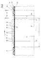
Wie Fig. 1 erkennen läßt, weist eine Vorrichtung zur Herstellung von Kunststoff-Verbundrohren mit Querrillen einen Maschinentisch 1 auf, auf dem Halbkokillen 2 bzw. 2' angeordnet sind, die jeweils zu zwei sogenannten Ketten 3 bzw. 3' miteinander verbunden sind. Hierzu ist an jeder Halbkokille 2 bzw. 2' in ihrem außerliegenden, in Produktionsrichtung 4 vorderen Bereich eine Lasche 5 mittels eines Anlenkbolzens 6 angelenkt, die an der entsprechenden Stelle der nachfolgenden Halbkokille 2 bzw. 2' ebenfalls mittels eines solchen Anlenkbolzens 6 angebracht ist. Die so gebildeten Ketten 3, 3' sind an ihrem in Produktionsrichtung 4 gesehen rückwärtigen Ende über als sogenannte Einlaufrollen 7 dienende Umlenkräder geführt. Die einzelnen Halbkokillen 2, 2' werden beim Umlauf der Ketten 3, 3' entsprechend den Umlaufrichtungspfeilen 8 bzw. 8' in eine Formstrecke 9 eingeschwenkt, in der jeweils zwei Halbkokillen 2, 2' zu einem Kokillenpaar vereinigt werden, wobei wiederum in Produktionsrichtung 4 hintereinanderfolgende Kokillenpaare dicht an dicht liegen. Um ein schnelles Schließen der Halbkokillen 2, 2' zu einer parallelen und aneinanderliegenden Stellung zu erreichen, sind sogenannte Schließrollen 10 vorgesehen, die die in Produktionsrichtung 4 hinteren Enden der Halbkokillen 2, 2' beschleunigt zusammenführen.As can be seen Fig. 1, a device for the production of plastic composite pipes with transverse grooves on a machine table 1, on the half-
In der Formstrecke 9 selber werden die aneinanderliegenden Halbkokillen 2, 2' mittels Führungsrollen 11, die in Führungsleisten 12 drehbar gelagert sind, gegeneinander gedrückt. Die Einlaufrollen 7 sind um Achszapfen 13 drehbar am Maschinentisch 1 angebracht. Am in Produktionsrichtung 4 vorderen Ende des Maschinentisches 1 sind ebenfalls als Umlenkräder dienende Rücklaufrollen 14 um Achszapfen 15 drehbar gelagert, um die die Ketten 3 bzw. 3' umgelenkt und zu den Einlaufrollen 7 zurückgeführt werden. Wie Fig. 1 zu entnehmen ist, enden die Führungsleisten 12 mit Führungsrollen 11 schon um die Länge mehrerer Halbkokillen 2 bzw. 2' vor den Rücklaufrollen 14, so daß die Halbkokillen 2 bzw. 2' wieder parallel zueinander und quer zur Produktionsrichtung 4 voneinander wegbewegt werden können, bevor sie von den Rücklaufrollen 14 verschwenkt werden.In the forming
An der Oberseite der Halbkokillen 2,2' ist eine Verzahnung 16 ausgebildet, wobei die beiden Verzahnungen 16 der einander paarweise zugeordneten Halbkokillen 2, 2' miteinander fluchten, so daß von oben ein gemeinsames Antriebsritzel 17 in diese Verzahnung 16 eingreifen kann, das die Halbkokillen 2, 2' in der Formstrecke 9 als geschlossene Form durch die Formstrecke 9 schiebt. Der Antrieb dieses Antriebsritzels 17 erfolgt in üblicher Weise von einem nicht dargestellten Motor über ein Antriebszahnrad 18, das auf einer Welle 19 drehfest befestigt ist, die wiederum das Antriebsritzel 17 trägt. Die Welle 19 ist in einem Lagerbock 20 gelagert, der über Distanzprismen 21 gegenüber dem Maschinentisch abgestützt und mit letzterem mittels Schrauben 22 fest verbunden ist.On the upper side of the half-
Auf der dargestellten Vorrichtung werden Kunststoff-Rohre 23, und zwar sogenannte Verbundrohre, mit unter anderem einer Querprofilierung, d.h. mit über deren Umfang umlaufenden Rillen 24 hergestellt.On the illustrated device
Die Rohre 23 werden weiter unten noch genauer beschrieben. Hierzu ist ein Extruder vorgesehen, von dem nur der weiter unten noch genauer zu beschreibende Spritzkopf 25 angedeutet ist. Die bisher beschriebene Vorrichtung ist bekannt, und zwar beispielsweise aus der EP-A 0 065 729 (entsprechend US 4 492 551) und aus der DE 40 21 564 A1.The
Wie primär Fig. 2 zu entnehmen ist, ist konzentrisch zu einer gemeinsamen Mittel-Längs-Achse 26 des Spritzkopfes 25 und der Formstrecke 9 ist am Spritzkopf 25 ein in die Formstrecke 9 hineinragender Düsenkörper 27 angebracht, in dem ein Außen-Kanal 28 und ein Innen-Kanal 29 ausgebildet sind. Der Außen-Kanal 28 endet in einer Außen-Düse 30, der Innen-Kanal 29 endet in einer Innen-Düse 31. Die Weite a der Außen-Düse 30 und die Weite b der Innen-Düse 31 ist jeweils dadurch einstellbar, daß ein die jeweilige Düse 30 bzw. 31 auf der Außenseite begrenzender Düsenring 32 mittels einer Düsenringmutter 33 in Richtung der Achse 26 bzw. der Produktionsrichtung 4 verstellbar ist. Die Düsenringmutter 33 ist jeweils auf einem entsprechenden Gewinde 34 am Düsenkörper 27 verstellbar.As can be seen primarily in FIG. 2, concentric with a common central
An den Düsenkörper 27 schließt sich in Produktionsrichtung 4 eine Kalibrier-und Temperierglocke 35 an. Diese ist mit einem ebenfalls konzentrisch zur Achse 26 angeordneten in üblicher Weise ausgestalteten, im wesentlichen zylindrischen Kalibrierzylinder 36 versehen, der auf einem Temperierzylinder 37 angeordnet ist. An der Außenseite des Temperierzylinders 37, d.h. an der Innenseite des Kalibrierzylinders 36 ist ein Temperier-Kanal 38 ausgebildet, durch den ein Temperiermedium, also ein Kühlmedium oder ein Heizmedium, geleitet werden kann.The
Wie Fig. 2 erkennen läßt, sind in den Halbkokillen, von denen in Fig. 2 nur die Halbkobllen 2 dargestellt sind, ringförmige Formausnehmung 39 ausgebildet, die in bekannter Weise an Teil-Vakuum-Kanäle 40 angeschlossen sind.As can be seen Fig. 2, in the half-molds, of which in Fig. 2, only the
Die vom Extruder durch den Spritzkopf 25 zugeführte Kunststoffschmelze strömt zum Teil durch den Außen-Kanal 28 zur Außen-Düse 30, aus der ein Außen-Schlauch 41 extrudiert wird, der sich unter Formung eines mit den Querrillen 24 versehenen Schlauches aufgrund des Teilvakuums in die Formausnehmungen 39 legt. Er bildet nach entsprechender Abkühlung und Erstarrung das gewellte Außenrohr 42 des Rohres 23.The supplied from the extruder through the
Ein anderer Teil der Schmelze strömt durch den Innen-Kanal 29 zur Innen-Düse 31, aus der ein weiterer Schlauch, nämlich der Innen-Schlauch 43 austritt, der auf den Kalibrierzylinder 36 gelangt. Dieser erweitert sich von der Innen-Düse 31 in Produktionsrichtung 4 leicht nach außen bis der Innen-Schlauch 43 gegen die Wellentäler 44 des Außen-Schlauches 41 gelangt und hier mit diesen verschweißt wird. Der Innen-Schlauch 43 bildet nach Abkühlung unter Erstarrung das Innenrohr 45 des Verbundrohres 23.Another part of the melt flows through the
Wie aus Fig. 2 ersichtlich ist, sind die Halbkokillen 2, 2' so ausgebildet, daß jeweils in vorgegebenen Abständen innerhalb des endlos hergestellten Verbundrohres 23 sogenannte Spitzenden 46 ausgebildet werden. Hierzu ist in einem Paar von Halbkobllen 2, 2' eine im wesentlichen zylindrischen Spitzende-Ausnehmung 47 ausgebildet, die also eine im wesentlichen zylindrische Wand 48 aufweist. Ein Spitzende 46 muß sich naturgemäß nicht über die volle Länge eines Paares von Halbkokillen 2, 2' in Produktionsrichtung 4 erstrekken; sie kann sich auch nur über einen Teil dieser Länge erstrecken. Der Durchmesser D der zylindrischen Wand 48 ist also im Vergleich zum Durchmesser d des Kalibrierzylinders 36 um die doppelte Wanddicke c des zu erzeugenden Spitzendes 46 größer. Das Verschweißen von Außen-Schlauch 41 und Innen-Schlauch 43 erfolgt hierbei nur durch das Zusammenpressen der beiden Schläuche 41, 43 zwischen dem Kalibrierzylinder 36 und der Wand 48 der Spitzende-Ausnehmung 47. Die Geschwindigkeit der Form kann hierbei durch entsprechende Ansteuerung des Antriebsmotors für das Antriebsritzel 17 zurückgenommen worden sein, so daß mehr Schmelze pro Längeneinheit des zu erzeugenden Rohres 23 in das Spitzende 46 gelangt als zur Erzeugung des mit Rillen 24 versehenen Verbundrohres 23, so daß die Wanddicke c des Spitzendes 46 größer ist als die Summe der Wanddicken e und f von Außenrohr 42 und Innenrohr 45. Um Pressungen der Schmelze bei der Herstellung des Spitzendes 46 zwischen Wand 48 und Kalibrierzylinder 36 aufgrund nicht exakter Dosierung durch den Extruder zu vermeiden, sind in der zylindrischen Wand 48 der entsprechenden Halbkokillen 2, 2' in Form schmaler Ringe ausgebildete Kompensationskammern 49 ausgebildet, in die Vakuumschlitze 50 einmünden, die jeweils mit einem Teil-Vakuum-Kanal 40 verbunden. Die Kompensationskammern 49 sind also einerseits mit dem zur Ausformung eines Spitzendes 46 dienenden SpitzendeFormraum 51 offen und andererseits an einen Teil-Vakuum-Kanal 40 angeschlossen. In diese Kompensationskammern 49 kann überschüssige Schmelze, die zur Füllung des Spitzende-Formraums 51 nicht benötigt wird, ausweichen, ohne daß es zu Beschädigungen des Spitzendes 46 kommt. Derartige Beschädigungen können auch dadurch auftreten, daß aufgrund zu hohen Druckes im Spitzende-Formraum die Reibung zwischen Schmelze und Kalibrierzylinder 36 zu groß wird. Da die Kompensationskammern 49 an die Teil-Vakuum-Kanäle 40 angeschlossen sind, kann überschüssige Schmelze tatsächlich auch in diese eintreten. Die radial zur Achse 25 gemessene Tiefe g der Kompensationskammern 49 von der Wand 48 aus und deren Breite h in Produktionsrichtung 4 hängt wesentlich von den rheologischen Eigenschaften der Schmelze ab, und zwar primär von deren Viskosität. Ihre Dimensionierung hängt davon ab, daß einerseits die zum Verschweißen von Innen-Schlauch 45 und Außen-Schlauch 41 notwendigen Drücke erzeugt werden, ohne daß extreme Überdrücke durch eventuellen Überfluß an Schmelze im Spitzende-Formraum 51 aufgefangen werden müssen. Für die Breite h der Kompensationskammern 49 in Produktionsrichtung 4 im Vergleich zur Breite i der Vakuumschlitze 50 ebenfalls in Produktionsrichtung 4 gilt: h ≤ 2i.As can be seen from Fig. 2, the half-
Die Kompensationskammern können sich auch parallel zur Achse 26 erstrecken, ansonsten aber gleich dimensioniert und an die Teil-Vakuum-Kanäle angeschlossen sein.The compensation chambers may also extend parallel to the
Wie Fig. 3 entnehmbar ist, führen die Kompensationskammern 49 dazu, daß auf der Außenwand 52 eines Spitzendes 46 kleine umlaufende stegartige Vorsprünge 53 gebildet werden, deren Abmessungen maximal denen der Kompensationskammer 49 entsprechen. Es sei in diesem Zusammenhang darauf hingewiesen, daß die Breite der Vakuumschlitze 50 so klein ist, daß Schmelze nicht in diese gelangen kann. Wie Fig. 3 weiterhin entnehmbar ist, werden die Vorsprünge 53 entgegen der Produktionsrichtung 4 größer und breiter. Dies hat seine Ursache darin, daß nicht die gesamte überschüssige Schmelze von Anfang an ausschließlich in die Kompensationskammern 49 gedrückt wird, sondern auch teilweise entgegen der Produktionsrichtung 4 zurückstaut, so daß mit zunehmender Ausbildung eines Spitzendes der relative Schmelzeüberfluß zunimmt mit der Folge, daß mehr Schmelze in die Kompensationskammern 49 gedrückt wird bzw, ausweicht.As can be seen in FIG. 3, the
In Fig. 3 ist weiterhin ein Übergangsabschnitt 54 gezeigt, der - bezogen auf die Produktionsrichtung 4 - vorn, d.h. am Übergang vom mit Rillen 24 versehenen Verbundrohr 23 zum Spitzende 46 ausgebildet ist. Dieser Übergangsabschnitt 54 wird mittels zweier Sägeschnitte 55, 56 herausgetrennt. Es wird also ein kurzer durch den Übergangsabschnitt 54 gebildeter Rohrabschnitt herausgeschritten.In Fig. 3, a
In Fig. 3 ist strichpunktiert eine Muffe 57 dargestellt, die durch Aufmuffen des Spitzendes 46 - nach Abtrennen des Übergangsabschnittes 54 geformt ist. Auch sie trägt die Vorsprünge 53 auf ihrer Außenseite. Die Muffe 57 ist mit einer stark ausgeprägten Innennut 58 zur Aufnahme eines Dichtungsringes versehen. Der Innendurchmesser D' der zylindrischen Innenwand 59 der Muffe 57 ist etwa gleich oder unwesentlich größer als der Außendurchmesser d' des Rohres 23 mit den Rillen 24. Wie aus Fig. 3 hervorgeht, ist die axiale Länge I der Muffe 57 durch das Aufmuffen und insbesondere das Ausbilden der Innennut 58 geringer als die axiale Länge L' des Spitzendes 46.In Fig. 3, a
Fig. 4 zeigt eine Verbindung von zwei Rohren 23 miteinander, bei denen die angeformte Muffe 57 in der zu Fig. 3 beschriebenen Art und Weite hergestellt ist, wobei also die Muffe 57 über das mit Rillen 24 versehene, aus gewelltem Außenrohr 42 und glattem Innenrohr 45 bestehende Rohr 23 geschoben ist. In eine Rille 24 ist eine Dichtung 60 eingelegt. Demgegenüber zeigt Fig. 5 ein Verbundrohr 23 mit einer in der geschilderten Weise hergestellten Muffe 57, die auf ein glattwandiges Vollwandrohr 61 oder einen Rohrabschnitt in Form eines Vollwandrohres aufgeschoben ist. Hierbei ist in der Innennut 58 eine Dichtung 62 angeordnet, die dichtend gegen die glatte zylindrische Außenwand 63 des Vollwandrohres 61 anliegt.Fig. 4 shows a connection of two
Claims (8)
- A method for the continuous manufacture of a compound pipe (23) of plastic material, which comprises a smooth internal pipe (45) of continuously constant internal diameter, and an external pipe (42) provided with transverse grooves (24) with corrugation troughs (44) and welded together with the internal pipe (45), and a spigot 46 substantially smooth outside,- an external tube (41) being extruded;- the external tube (41), by partial vacuum applied from outside, being provided with a corrugation with transverse grooves (24) with corrugation troughs (44);- an internal tube (43) being extruded into the external tube (41);- the internal tube (43) being pressed against corrugation troughs (44) of the external tube (41), where it is welded together with the external tube (41);- the external tube (41) being formed at predetermined intervals to constitute an essentially smooth-walled, about cylindrical spigot 46; and- the internal tube (43) being pressed from inside full-face against the external tube (41);characterized- in that the external tube (41) is formed to constitute the spigot (46) by a partial vacuum being applied from outside, and- in that the external wall (52) of the external tube (41), in the vicinity of the spigot 46, is pressure-relieved in small surface sections where small projections (53) are thus formed as a compensation for inaccurate proportioning during the extrusion of the plastic material.
- A method according to claim 1, characterized in that the external wall (52) is pressure-relieved in annular zones.
- A method according to claim 1 or 2, characterized in that the small surface sections are pressure-relieved by partial vacuum.
- An apparatus for putting into practice the method according to one of claims 1 to 3,- half shells (2, 2') being disposed on a machine bed (1) for circulation and guidance in the direction (4) of production, which are provided with annular mold recesses (39) and of which two at a time combine as a pair on a molding path (9) to form a mold with a central longitudinal axis (26),- the mold recesses (39) being connected to partial vacuum channels (40) formed in the half shells (2, 2'),- an injection head (25) of an extruder being disposed upstream of the molding path (9),- the injection head (25) being provided with an external nozzle (30) for the extrusion of an external tube (41) and, downstream in the direction (4) of production, with an internal nozzle (31) for the extrusion of an internal tube (43) and, at its rear end seen in the direction (4) of production, with a calibrating and temperature-regulating bell (35) which is provided with a calibrating cylinder (36), and- at least one pair of half shells (2, 2') being provided with a spigot recess (47) with a substantially cylindrical wall (48),characterized in that compensation chambers (49) are formed in the substantially cylindrical wall (48) for the formation of projections (53), the dimensions of which correspond maximally to those of the compensation chambers (49).
- An apparatus according to claim 4, characterized in that the compensation chambers (49) are in the form of rings arranged concentrically to the central longitudinal axis (26).
- An apparatus according to claim 4 or 5, characterized in that the compensation chambers (49) are connected to partial vacuum channels (40).
- An apparatus according to claim 6, characterized in that the compensation chambers (49) are connected to partial vacuum channels (40) via vacuum slits (50).
- An apparatus according to claim 7, characterized in that h ≤ 2i applies to the width (h) of the compensation chambers (49) in comparison with the width (i) of the vacuum slits (50) in the direction (4) of production.
Applications Claiming Priority (2)
| Application Number | Priority Date | Filing Date | Title |
|---|---|---|---|
| DE4240268A DE4240268A1 (en) | 1992-12-01 | 1992-12-01 | Method and device for the continuous production of a composite pipe with an essentially smooth outer section |
| DE4240268 | 1992-12-01 |
Publications (3)
| Publication Number | Publication Date |
|---|---|
| EP0600214A1 EP0600214A1 (en) | 1994-06-08 |
| EP0600214B1 EP0600214B1 (en) | 1998-03-04 |
| EP0600214B2 true EP0600214B2 (en) | 2006-04-19 |
Family
ID=6474029
Family Applications (1)
| Application Number | Title | Priority Date | Filing Date |
|---|---|---|---|
| EP93117224A Expired - Lifetime EP0600214B2 (en) | 1992-12-01 | 1993-10-25 | Method and apparatus for the continuous manufacturing of a composite pipe having a substantially smooth external wall portion |
Country Status (6)
| Country | Link |
|---|---|
| US (1) | US5472659A (en) |
| EP (1) | EP0600214B2 (en) |
| CN (1) | CN1042712C (en) |
| CA (1) | CA2110360C (en) |
| DE (2) | DE4240268A1 (en) |
| ES (1) | ES2112943T3 (en) |
Cited By (8)
| Publication number | Priority date | Publication date | Assignee | Title |
|---|---|---|---|---|
| US7484535B2 (en) | 2005-03-14 | 2009-02-03 | Advanced Drainage Systems, Inc. | Corrugated pipe with outer layer |
| US7980841B2 (en) | 2007-02-26 | 2011-07-19 | Advanced Drainage Systems, Inc. | Defined ratio dual-wall pipe die |
| US7988438B2 (en) | 2008-02-11 | 2011-08-02 | Advanced Drainage Systems, Inc. | Extrusion die vacuum seals |
| US8114324B2 (en) | 2008-10-14 | 2012-02-14 | Advanced Drainage Systems, Inc. | Apparatus and method for pressing an outer wall of pipe |
| US8496460B2 (en) | 2007-02-26 | 2013-07-30 | Advanced Drainage Systems, Inc. | Pipe extrusion die flow path apparatus and method |
| US8550807B2 (en) | 2008-05-28 | 2013-10-08 | Advanced Drainage Systems, Inc. | In-mold punch apparatus and methods |
| US8733405B2 (en) | 2005-03-14 | 2014-05-27 | Advanced Drainage Systems, Inc. | Corrugated pipe with outer layer |
| US8820800B2 (en) | 2007-11-16 | 2014-09-02 | Advanced Drainage Systems, Inc. | Multi-wall corrugated pipe couplings and methods |
Families Citing this family (14)
| Publication number | Priority date | Publication date | Assignee | Title |
|---|---|---|---|---|
| DE19504501A1 (en) * | 1995-02-13 | 1996-08-14 | Wilhelm Hegler | Process and plant for producing a multilayer pipe made of thermoplastic, in particular polyolefin |
| DE19604311A1 (en) * | 1996-02-07 | 1997-08-14 | Ralph Peter Dr Ing Hegler | Composite pipe with sleeve and process for its manufacture |
| DE19640928A1 (en) * | 1996-10-04 | 1998-04-09 | Ralph Peter Dr Ing Hegler | Device for the production of plastic composite pipes |
| IT1290468B1 (en) * | 1997-03-21 | 1998-12-04 | Giancarlo Tamborini | EXHAUST PIPE STRUCTURE WITH SIMPLIFIED CONSTRUCTION PARTICULARLY DESIGNED FOR HOUSEHOLD APPLIANCES AND SIMILAR |
| DE19724113A1 (en) * | 1997-06-09 | 1998-12-10 | Ralph Peter Dr Hegler | Composite pipe with molded pipe sleeve and method for its production |
| DE19848470A1 (en) * | 1998-10-21 | 2000-04-27 | Ralph Peter Hegler | Process for the continuous production of a composite pipe with a pipe sleeve and device for carrying out the process |
| US6199592B1 (en) * | 1999-02-05 | 2001-03-13 | Hancor, Inc. | Pipe structure and method of manufacture |
| EP1317334B1 (en) * | 2000-09-11 | 2005-06-08 | Manfred Arno Alfred Lupke | Pipe forming apparatus for varying the volume of plastic along the pipe wall |
| US6752955B2 (en) | 2001-07-13 | 2004-06-22 | Trw Inc. | Method of manufacturing a boot seal |
| DE502004004881D1 (en) * | 2004-07-03 | 2007-10-18 | Hegler Ralph Peter | Method for the continuous production of a double-walled corrugated pipe with pipe socket, the double-walled corrugated pipe and the device for carrying out the method |
| EP1916087A1 (en) * | 2006-10-26 | 2008-04-30 | Drossbach GmbH & Co. KG | Device for applying plastic to a workpiece |
| ES2370484B1 (en) * | 2007-05-14 | 2012-11-27 | Uralita Sistemas De Tuberías, S.A. | MANUFACTURING PROCEDURE OF TRICAPA CORRUGATED PIPE, MANUFACTURING HEAD AND THE PIPE SO OBTAINED. |
| US8820801B2 (en) | 2007-11-16 | 2014-09-02 | Advanced Drainage System, Inc. | Multi-wall corrugated pipe couplings and methods |
| GB2474982B (en) * | 2008-08-06 | 2013-03-13 | Jain Irrigation Systems Ltd | A novel pipe with integral male and female ends, a novel jointmade using the same, and process of making the pipe and the joint |
Family Cites Families (7)
| Publication number | Priority date | Publication date | Assignee | Title |
|---|---|---|---|---|
| JPS6036143A (en) * | 1983-08-08 | 1985-02-25 | Takiron Co Ltd | Manufacture of double wall pipe with joint section |
| JPS61148035A (en) * | 1984-12-21 | 1986-07-05 | Takiron Co Ltd | Manufacture of double wall pipe |
| JPS61293821A (en) * | 1985-06-21 | 1986-12-24 | Takiron Co Ltd | Molding of sleeve on corrugated pipe |
| FI77405C (en) * | 1986-03-20 | 1989-03-10 | Uponor Nv | Method and apparatus for producing cam flange tubes. |
| DE3701822A1 (en) * | 1987-01-22 | 1988-08-11 | Uponor Nv | METHOD AND ARRANGEMENT FOR EXTRUDING PLASTIC PIPES |
| NL8701164A (en) * | 1987-05-14 | 1988-12-01 | Wavin Bv | PLASTIC TUBE WITH OUTSIDE MASSIVE CROSS RIBS, APPARATUS FOR APPLICATION IN AN INSTALLATION FOR THE FORMING OF SUCH PIPES; INSTALLATION FOR FORMING PIPES CONTAINING SUCH A DEVICE AND METHOD FOR FORMING A PLASTIC TUBE USING SUCH AN INSTALLATION |
| DE4210482A1 (en) * | 1992-03-31 | 1993-10-07 | Wilhelm Hegler | Method and device for the continuous production of a composite pipe with a pipe socket |
-
1992
- 1992-12-01 DE DE4240268A patent/DE4240268A1/en not_active Withdrawn
-
1993
- 1993-10-25 DE DE59308206T patent/DE59308206D1/en not_active Expired - Lifetime
- 1993-10-25 ES ES93117224T patent/ES2112943T3/en not_active Expired - Lifetime
- 1993-10-25 EP EP93117224A patent/EP0600214B2/en not_active Expired - Lifetime
- 1993-11-19 US US08/154,855 patent/US5472659A/en not_active Expired - Fee Related
- 1993-11-30 CA CA002110360A patent/CA2110360C/en not_active Expired - Fee Related
- 1993-11-30 CN CN93121112A patent/CN1042712C/en not_active Expired - Fee Related
Cited By (8)
| Publication number | Priority date | Publication date | Assignee | Title |
|---|---|---|---|---|
| US7484535B2 (en) | 2005-03-14 | 2009-02-03 | Advanced Drainage Systems, Inc. | Corrugated pipe with outer layer |
| US8733405B2 (en) | 2005-03-14 | 2014-05-27 | Advanced Drainage Systems, Inc. | Corrugated pipe with outer layer |
| US7980841B2 (en) | 2007-02-26 | 2011-07-19 | Advanced Drainage Systems, Inc. | Defined ratio dual-wall pipe die |
| US8496460B2 (en) | 2007-02-26 | 2013-07-30 | Advanced Drainage Systems, Inc. | Pipe extrusion die flow path apparatus and method |
| US8820800B2 (en) | 2007-11-16 | 2014-09-02 | Advanced Drainage Systems, Inc. | Multi-wall corrugated pipe couplings and methods |
| US7988438B2 (en) | 2008-02-11 | 2011-08-02 | Advanced Drainage Systems, Inc. | Extrusion die vacuum seals |
| US8550807B2 (en) | 2008-05-28 | 2013-10-08 | Advanced Drainage Systems, Inc. | In-mold punch apparatus and methods |
| US8114324B2 (en) | 2008-10-14 | 2012-02-14 | Advanced Drainage Systems, Inc. | Apparatus and method for pressing an outer wall of pipe |
Also Published As
| Publication number | Publication date |
|---|---|
| CN1096480A (en) | 1994-12-21 |
| ES2112943T3 (en) | 1998-04-16 |
| EP0600214B1 (en) | 1998-03-04 |
| CN1042712C (en) | 1999-03-31 |
| CA2110360C (en) | 2005-01-25 |
| EP0600214A1 (en) | 1994-06-08 |
| DE59308206D1 (en) | 1998-04-09 |
| CA2110360A1 (en) | 1994-06-02 |
| DE4240268A1 (en) | 1994-06-09 |
| US5472659A (en) | 1995-12-05 |
Similar Documents
| Publication | Publication Date | Title |
|---|---|---|
| EP0600214B2 (en) | Method and apparatus for the continuous manufacturing of a composite pipe having a substantially smooth external wall portion | |
| EP0789176B1 (en) | Composite pipe with a sleeve and method of manufacturing the same | |
| EP0890770B1 (en) | Composite pipe with integrally formed socket and method of manufacturing the same | |
| EP0563575B1 (en) | Method and apparatus for continuous production of a composite pipe with sleeve | |
| EP0301189B1 (en) | Method and apparatus for manufacturing a ribbed plastic pipe | |
| DE1704718A1 (en) | Method and device for the production of plastic pipes with an annular or helical grooved outer wall | |
| DE3737588C3 (en) | Method for producing an internally smooth, externally finned tube made of extrudable plastic and device for carrying out the method | |
| EP0834386B1 (en) | Apparatus for producing double walled plastic pipes | |
| DE2403618B2 (en) | Device for producing a double-walled plastic pipe | |
| EP2452803B1 (en) | Device for producing corrugated thermoplastic tubes | |
| EP2065159A1 (en) | Device for continuously manufacturing a connecting pipe with pipe sleeve | |
| EP0580984B1 (en) | Apparatus for producing a corrugated plastic pipe | |
| DE102006048512B4 (en) | Apparatus for producing composite pipes | |
| EP0464411B1 (en) | Apparatus for the manufacture of plastic pipes | |
| DE2359746A1 (en) | METHOD FOR MANUFACTURING PIPE ELBOWS FROM THERMOPLASTIC PLASTIC AND DEVICE FOR CARRYING OUT THE METHOD | |
| DE2104294A1 (en) | ||
| DE19701970A1 (en) | Method and device for producing an enveloping corrugated tube with a line located therein | |
| DE19941160A1 (en) | Cylinder for a screw extruder with channels for a temperature control medium | |
| DE102009035040B4 (en) | Process for the continuous production of a pipe and apparatus for carrying out the process | |
| EP3153296A1 (en) | Extrusion head for a device for producing a composite pipe | |
| DE4005996C2 (en) | Joining process for a roller body | |
| DE3426680C2 (en) | ||
| DE3235146C2 (en) | Connection of a flexible hose to a pipe and a method for producing a connecting pipe end for the connection of a hose | |
| EP2436504A2 (en) | Method for continuous manufacture of a connecting rod with rod fitting, connecting rod with rod fitting and device for executing the method and manufacturing the connecting rod | |
| DE2213561A1 (en) | METHOD AND DEVICE FOR FORMING A SLEEVE WITH A CIRCULAR CORRUGATION AT THE END OF A PIPE MADE OF THERMOPLASTIC PLASTIC |
Legal Events
| Date | Code | Title | Description |
|---|---|---|---|
| PUAI | Public reference made under article 153(3) epc to a published international application that has entered the european phase |
Free format text: ORIGINAL CODE: 0009012 |
|
| AK | Designated contracting states |
Kind code of ref document: A1 Designated state(s): DE ES FR GB IT SE |
|
| 17P | Request for examination filed |
Effective date: 19940511 |
|
| 17Q | First examination report despatched |
Effective date: 19950905 |
|
| GRAG | Despatch of communication of intention to grant |
Free format text: ORIGINAL CODE: EPIDOS AGRA |
|
| GRAG | Despatch of communication of intention to grant |
Free format text: ORIGINAL CODE: EPIDOS AGRA |
|
| GRAH | Despatch of communication of intention to grant a patent |
Free format text: ORIGINAL CODE: EPIDOS IGRA |
|
| GRAH | Despatch of communication of intention to grant a patent |
Free format text: ORIGINAL CODE: EPIDOS IGRA |
|
| GRAA | (expected) grant |
Free format text: ORIGINAL CODE: 0009210 |
|
| AK | Designated contracting states |
Kind code of ref document: B1 Designated state(s): DE ES FR GB IT SE |
|
| GBT | Gb: translation of ep patent filed (gb section 77(6)(a)/1977) |
Effective date: 19980305 |
|
| REF | Corresponds to: |
Ref document number: 59308206 Country of ref document: DE Date of ref document: 19980409 |
|
| REG | Reference to a national code |
Ref country code: ES Ref legal event code: FG2A Ref document number: 2112943 Country of ref document: ES Kind code of ref document: T3 |
|
| ITF | It: translation for a ep patent filed |
Owner name: STUDIO TORTA S.R.L. |
|
| ET | Fr: translation filed | ||
| PG25 | Lapsed in a contracting state [announced via postgrant information from national office to epo] |
Ref country code: SE Free format text: LAPSE BECAUSE OF FAILURE TO SUBMIT A TRANSLATION OF THE DESCRIPTION OR TO PAY THE FEE WITHIN THE PRESCRIBED TIME-LIMIT Effective date: 19980604 |
|
| PLBQ | Unpublished change to opponent data |
Free format text: ORIGINAL CODE: EPIDOS OPPO |
|
| PLBI | Opposition filed |
Free format text: ORIGINAL CODE: 0009260 |
|
| PLBF | Reply of patent proprietor to notice(s) of opposition |
Free format text: ORIGINAL CODE: EPIDOS OBSO |
|
| 26 | Opposition filed |
Opponent name: CORMA INC. Effective date: 19981203 |
|
| PLBF | Reply of patent proprietor to notice(s) of opposition |
Free format text: ORIGINAL CODE: EPIDOS OBSO |
|
| PLBF | Reply of patent proprietor to notice(s) of opposition |
Free format text: ORIGINAL CODE: EPIDOS OBSO |
|
| PLBF | Reply of patent proprietor to notice(s) of opposition |
Free format text: ORIGINAL CODE: EPIDOS OBSO |
|
| RAP2 | Party data changed (patent owner data changed or rights of a patent transferred) |
Owner name: HEGLER, RALPH PETER, DR.-ING. |
|
| REG | Reference to a national code |
Ref country code: GB Ref legal event code: IF02 |
|
| PLBO | Opposition rejected |
Free format text: ORIGINAL CODE: EPIDOS REJO |
|
| PLBO | Opposition rejected |
Free format text: ORIGINAL CODE: EPIDOS REJO |
|
| PLAW | Interlocutory decision in opposition |
Free format text: ORIGINAL CODE: EPIDOS IDOP |
|
| APAC | Appeal dossier modified |
Free format text: ORIGINAL CODE: EPIDOS NOAPO |
|
| APAC | Appeal dossier modified |
Free format text: ORIGINAL CODE: EPIDOS NOAPO |
|
| PLBQ | Unpublished change to opponent data |
Free format text: ORIGINAL CODE: EPIDOS OPPO |
|
| PLAB | Opposition data, opponent's data or that of the opponent's representative modified |
Free format text: ORIGINAL CODE: 0009299OPPO |
|
| R26 | Opposition filed (corrected) |
Opponent name: CORMA INC. Effective date: 19981203 |
|
| REG | Reference to a national code |
Ref country code: GB Ref legal event code: 732E |
|
| PGFP | Annual fee paid to national office [announced via postgrant information from national office to epo] |
Ref country code: ES Payment date: 20041026 Year of fee payment: 12 |
|
| APAA | Appeal reference recorded |
Free format text: ORIGINAL CODE: EPIDOS REFN |
|
| APBU | Appeal procedure closed |
Free format text: ORIGINAL CODE: EPIDOSNNOA9O |
|
| APAH | Appeal reference modified |
Free format text: ORIGINAL CODE: EPIDOSCREFNO |
|
| PG25 | Lapsed in a contracting state [announced via postgrant information from national office to epo] |
Ref country code: IT Free format text: LAPSE BECAUSE OF NON-PAYMENT OF DUE FEES Effective date: 20051025 |
|
| PUAH | Patent maintained in amended form |
Free format text: ORIGINAL CODE: 0009272 |
|
| STAA | Information on the status of an ep patent application or granted ep patent |
Free format text: STATUS: PATENT MAINTAINED AS AMENDED |
|
| 27A | Patent maintained in amended form |
Effective date: 20060419 |
|
| AK | Designated contracting states |
Kind code of ref document: B2 Designated state(s): DE ES FR GB IT SE |
|
| GBTA | Gb: translation of amended ep patent filed (gb section 77(6)(b)/1977) | ||
| PG25 | Lapsed in a contracting state [announced via postgrant information from national office to epo] |
Ref country code: ES Free format text: LAPSE BECAUSE OF FAILURE TO SUBMIT A TRANSLATION OF THE DESCRIPTION OR TO PAY THE FEE WITHIN THE PRESCRIBED TIME-LIMIT Effective date: 20060730 |
|
| PGFP | Annual fee paid to national office [announced via postgrant information from national office to epo] |
Ref country code: DE Payment date: 20061129 Year of fee payment: 14 |
|
| ET3 | Fr: translation filed ** decision concerning opposition | ||
| PG25 | Lapsed in a contracting state [announced via postgrant information from national office to epo] |
Ref country code: DE Free format text: LAPSE BECAUSE OF THE APPLICANT RENOUNCES Effective date: 20070723 |
|
| REG | Reference to a national code |
Ref country code: FR Ref legal event code: ST Effective date: 20080630 |
|
| PGFP | Annual fee paid to national office [announced via postgrant information from national office to epo] |
Ref country code: FR Payment date: 20061020 Year of fee payment: 14 |
|
| PG25 | Lapsed in a contracting state [announced via postgrant information from national office to epo] |
Ref country code: FR Free format text: LAPSE BECAUSE OF NON-PAYMENT OF DUE FEES Effective date: 20071031 |
|
| PGFP | Annual fee paid to national office [announced via postgrant information from national office to epo] |
Ref country code: GB Payment date: 20081024 Year of fee payment: 16 |
|
| PG25 | Lapsed in a contracting state [announced via postgrant information from national office to epo] |
Ref country code: GB Free format text: LAPSE BECAUSE OF NON-PAYMENT OF DUE FEES Effective date: 20091025 |