EP0597152A1 - Optimizing capillary flow cells - Google Patents
Optimizing capillary flow cells Download PDFInfo
- Publication number
- EP0597152A1 EP0597152A1 EP92203488A EP92203488A EP0597152A1 EP 0597152 A1 EP0597152 A1 EP 0597152A1 EP 92203488 A EP92203488 A EP 92203488A EP 92203488 A EP92203488 A EP 92203488A EP 0597152 A1 EP0597152 A1 EP 0597152A1
- Authority
- EP
- European Patent Office
- Prior art keywords
- capillary
- flow cell
- flow cells
- capillary flow
- light
- Prior art date
- Legal status (The legal status is an assumption and is not a legal conclusion. Google has not performed a legal analysis and makes no representation as to the accuracy of the status listed.)
- Withdrawn
Links
- 230000035945 sensitivity Effects 0.000 claims abstract description 9
- 239000000835 fiber Substances 0.000 claims abstract description 8
- 230000002708 enhancing effect Effects 0.000 claims abstract 2
- 238000005553 drilling Methods 0.000 claims description 2
- 239000003292 glue Substances 0.000 claims description 2
- 238000001514 detection method Methods 0.000 abstract description 4
- 238000000034 method Methods 0.000 abstract description 4
- 230000003287 optical effect Effects 0.000 abstract description 2
- VYPSYNLAJGMNEJ-UHFFFAOYSA-N Silicium dioxide Chemical compound O=[Si]=O VYPSYNLAJGMNEJ-UHFFFAOYSA-N 0.000 abstract 2
- 239000005350 fused silica glass Substances 0.000 abstract 2
- 238000003981 capillary liquid chromatography Methods 0.000 abstract 1
- 238000005515 capillary zone electrophoresis Methods 0.000 abstract 1
- 238000011209 electrochromatography Methods 0.000 abstract 1
- 239000011521 glass Substances 0.000 abstract 1
- 238000004519 manufacturing process Methods 0.000 abstract 1
- 238000004244 micellar electrokinetic capillary chromatography Methods 0.000 abstract 1
- 238000004808 supercritical fluid chromatography Methods 0.000 abstract 1
- 238000005457 optimization Methods 0.000 description 5
- 230000007423 decrease Effects 0.000 description 2
- 230000005540 biological transmission Effects 0.000 description 1
- 239000006185 dispersion Substances 0.000 description 1
- 239000012530 fluid Substances 0.000 description 1
- 238000012544 monitoring process Methods 0.000 description 1
- 239000013307 optical fiber Substances 0.000 description 1
- 238000000926 separation method Methods 0.000 description 1
Images


Classifications
-
- G—PHYSICS
- G01—MEASURING; TESTING
- G01N—INVESTIGATING OR ANALYSING MATERIALS BY DETERMINING THEIR CHEMICAL OR PHYSICAL PROPERTIES
- G01N30/00—Investigating or analysing materials by separation into components using adsorption, absorption or similar phenomena or using ion-exchange, e.g. chromatography or field flow fractionation
- G01N30/02—Column chromatography
- G01N30/62—Detectors specially adapted therefor
- G01N30/74—Optical detectors
-
- G—PHYSICS
- G01—MEASURING; TESTING
- G01N—INVESTIGATING OR ANALYSING MATERIALS BY DETERMINING THEIR CHEMICAL OR PHYSICAL PROPERTIES
- G01N21/00—Investigating or analysing materials by the use of optical means, i.e. using sub-millimetre waves, infrared, visible or ultraviolet light
- G01N21/01—Arrangements or apparatus for facilitating the optical investigation
- G01N21/03—Cuvette constructions
- G01N21/05—Flow-through cuvettes
-
- G—PHYSICS
- G01—MEASURING; TESTING
- G01N—INVESTIGATING OR ANALYSING MATERIALS BY DETERMINING THEIR CHEMICAL OR PHYSICAL PROPERTIES
- G01N21/00—Investigating or analysing materials by the use of optical means, i.e. using sub-millimetre waves, infrared, visible or ultraviolet light
- G01N21/01—Arrangements or apparatus for facilitating the optical investigation
- G01N21/03—Cuvette constructions
- G01N2021/0346—Capillary cells; Microcells
-
- G—PHYSICS
- G01—MEASURING; TESTING
- G01N—INVESTIGATING OR ANALYSING MATERIALS BY DETERMINING THEIR CHEMICAL OR PHYSICAL PROPERTIES
- G01N21/00—Investigating or analysing materials by the use of optical means, i.e. using sub-millimetre waves, infrared, visible or ultraviolet light
- G01N21/01—Arrangements or apparatus for facilitating the optical investigation
- G01N21/03—Cuvette constructions
- G01N21/05—Flow-through cuvettes
- G01N2021/052—Tubular type; cavity type; multireflective
-
- G—PHYSICS
- G01—MEASURING; TESTING
- G01N—INVESTIGATING OR ANALYSING MATERIALS BY DETERMINING THEIR CHEMICAL OR PHYSICAL PROPERTIES
- G01N30/00—Investigating or analysing materials by separation into components using adsorption, absorption or similar phenomena or using ion-exchange, e.g. chromatography or field flow fractionation
- G01N30/02—Column chromatography
- G01N30/62—Detectors specially adapted therefor
- G01N30/74—Optical detectors
- G01N2030/746—Optical detectors detecting along the line of flow, e.g. axial
-
- G—PHYSICS
- G01—MEASURING; TESTING
- G01N—INVESTIGATING OR ANALYSING MATERIALS BY DETERMINING THEIR CHEMICAL OR PHYSICAL PROPERTIES
- G01N21/00—Investigating or analysing materials by the use of optical means, i.e. using sub-millimetre waves, infrared, visible or ultraviolet light
- G01N21/01—Arrangements or apparatus for facilitating the optical investigation
- G01N21/03—Cuvette constructions
- G01N21/0303—Optical path conditioning in cuvettes, e.g. windows; adapted optical elements or systems; path modifying or adjustment
-
- G—PHYSICS
- G01—MEASURING; TESTING
- G01N—INVESTIGATING OR ANALYSING MATERIALS BY DETERMINING THEIR CHEMICAL OR PHYSICAL PROPERTIES
- G01N2201/00—Features of devices classified in G01N21/00
- G01N2201/06—Illumination; Optics
- G01N2201/063—Illuminating optical parts
- G01N2201/0638—Refractive parts
- G01N2201/0639—Sphere lens
Definitions
- Figure 5 shows the aperture ratios (dc/Ic) for cylindrical flow cells with volumes ranging from 2 to 20 nl.
- Both Z and U shaped capillary flow cells can be considered as cylindrical cells and should be constructed with respect to the optimal aperture ratio, shown by the shaded area in Figure 5 and the arrows indicating the directions for aperture optimization.
- the optical aperture (dc/Ic) should have numbers within the range of 1/10 to 1/5.
- the utilizable light energy rapidly decreases, resulting in increased noise and poor linearity.
- For values above 1/5 the path length becomes to short, resulting in poor sensitivity.
- capillary of 3 mm path length values closer to the optimal ratio of 1/10 result.
- the substantial decrease of 5 to 10 fold in noise from using flow cells with a path lengths 10 mm counterbalance the drawbacks of loosing some of the sensitivity (ca. factor 2) versus capillary flow cells of 20 mm path length.
- the risk of zone overlap and dispersion in the longitudinal section of the capillary flow cell is significantly reduced with flow cells of shorter path length.
- Figure 3 shows a Z shaped capillary flow cell with an input and output optical fiber [6].
- input and output optical fiber [6] For highest light throughput the use of tapered fibers and direct attachment of the fibers onto the bends of the capillary using UV transparent glue [5] is recommended.
- fiber optics allows the separation of the sensing region (flow cell) from the detection device which offers new types of applications, e.g. process monitoring, high temperature detection, etc.
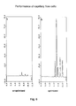
- FIG. 6 shows the comparison of a previous capillary flow cell and a U-shaped capillary flow cell with optimized entrance angle and optimized aperture ratio. Sensitivity enhancement of at least a factor of 10 and more are possible, resulting in lower limits of detection of the same magnitude.
Abstract
The sensitivity of capillary flow cells such as described in the European patent application nr. 90200691.5 has been substantially improved by optimizing the alignment of the longitudinal section (middle part) of the bent fused silica capillary, by increasing the aperture ratio (flow cell diameter/flow cell length) and by making use of fiber optics for light beam guiding and enhancing the light propagation through the capillary flow cell.
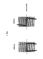
These improvements can be applied to any type of longitudinal flow cells including "Z" and "U" shaped capillary flow cells (Figure 1).
The alignment of the middle part [2] of the bent fused silica capillary [3,4] is no longer parallel to the optical axes but shows a deviation by angle ψ - (Figure 2). This angle is of the same value as the angle by which the light beam is refracted during its entrance into the capillary glass tubing and, therefore, compensates for loss in refracted light.
With aperture ratios (dc/Ic) of typically 1/260 the ratios are to far away from their optimum values of 1/10 to 1/5 and result in high noise levels.
By adapting the ratios to values closer to the optimum (e.g. 1/40) noise levels can be reduced substantially.
The use of fiber optics [6] allows for optimal light beam guiding to and from the capillary flow cell and increases the light throughput (Figure 3). Further it allows for placing the flow cell (sensing region) in distance to the detection device.
This invention relates to a capillary flow cell for use in microseparation techniques such as capillary liquid chromatography, supercritical fluid chromatography, capillary electroseparations (e.g., capillary zone electrophoresis, micellar electrokinetic capillary chromatography, electrochromatography) and related techniques and to a method for manufacturing capillary flow cells of improved sensitivity.
Description
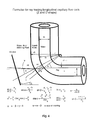
- In Figure 4 the formulas for ray tracing of capillary flow cells are shown. The theoretical calculations illustrate that U shaped flow cells provide higher light transmission than Z shaped capillary flow cells owing to the entrance and
exit angle 0. In practice, however, no difference in sensitivity between Z and U shaped flow cells could be observed. Correction for the reflection of the incident light beam was realized by drilling the bore [2] of the middle portion of the template [1] with angle 0 (Figure 2). The need for refractive index matching fluids (RIMF) was therefore eliminated. - Figure 5 shows the aperture ratios (dc/Ic) for cylindrical flow cells with volumes ranging from 2 to 20 nl. Both Z and U shaped capillary flow cells can be considered as cylindrical cells and should be constructed with respect to the optimal aperture ratio, shown by the shaded area in Figure 5 and the arrows indicating the directions for aperture optimization. For highest sensitivity the optical aperture (dc/Ic) should have numbers within the range of 1/10 to 1/5. For values below 1/10 the utilizable light energy rapidly decreases, resulting in increased noise and poor linearity. For values above 1/5 the path length becomes to short, resulting in poor sensitivity. With a ratio of ca. 1/40 achieved by using a 75 µm I.D. capillary of 3 mm path length, values closer to the optimal ratio of 1/10 result. The substantial decrease of 5 to 10 fold in noise from using flow cells with a
path lengths 10 mm counterbalance the drawbacks of loosing some of the sensitivity (ca. factor 2) versus capillary flow cells of 20 mm path length. Further, the risk of zone overlap and dispersion in the longitudinal section of the capillary flow cell is significantly reduced with flow cells of shorter path length. - The use of fiber optics can significantly enhance the propagation of the light beam through the capillary flow cell. Figure 3 shows a Z shaped capillary flow cell with an input and output optical fiber [6]. For highest light throughput the use of tapered fibers and direct attachment of the fibers onto the bends of the capillary using UV transparent glue [5] is recommended.
- Further, the use of fiber optics allows the separation of the sensing region (flow cell) from the detection device which offers new types of applications, e.g. process monitoring, high temperature detection, etc.
- With these optimizations, the sensitivity of capillary flow cells in terms of signal to noise (S/N) values can be significantly improved. Figure 6 shows the comparison of a previous capillary flow cell and a U-shaped capillary flow cell with optimized entrance angle and optimized aperture ratio. Sensitivity enhancement of at least a factor of 10 and more are possible, resulting in lower limits of detection of the same magnitude.
Claims (3)
- Making and optimizing longitudinal capillary flow cells that can be achieved either by: 1. Minimizing the amount of refracted light and consequently increasing the light throughput by either correcting the incident light beam by angle ψ (use of lenses) or by drilling the central bore of the template with a deviation of the same angle.
- 2. Increasing the sensitivity (in terms of S/N) by reducing the aperture ratio dc/Ic to values closer to the optimum of 1/10, by reducing the path length to values 10 mm.
- 3. Enhancing the light propagation through the flow cells by means of fiber optics, including the use of tapered fibers and UV transparent glue.
Priority Applications (3)
| Application Number | Priority Date | Filing Date | Title |
|---|---|---|---|
| EP92203488A EP0597152A1 (en) | 1992-11-13 | 1992-11-13 | Optimizing capillary flow cells |
| US08/151,165 US5423513A (en) | 1992-11-13 | 1993-11-12 | Method of and a capillary flow cell for analysing fluid samples |
| EP93203166A EP0597552A1 (en) | 1992-11-13 | 1993-11-12 | An improved method of and a capillary flow cell for analysing fluid samples |
Applications Claiming Priority (1)
| Application Number | Priority Date | Filing Date | Title |
|---|---|---|---|
| EP92203488A EP0597152A1 (en) | 1992-11-13 | 1992-11-13 | Optimizing capillary flow cells |
Publications (1)
| Publication Number | Publication Date |
|---|---|
| EP0597152A1 true EP0597152A1 (en) | 1994-05-18 |
Family
ID=8211039
Family Applications (1)
| Application Number | Title | Priority Date | Filing Date |
|---|---|---|---|
| EP92203488A Withdrawn EP0597152A1 (en) | 1992-11-13 | 1992-11-13 | Optimizing capillary flow cells |
Country Status (2)
| Country | Link |
|---|---|
| US (1) | US5423513A (en) |
| EP (1) | EP0597152A1 (en) |
Cited By (3)
| Publication number | Priority date | Publication date | Assignee | Title |
|---|---|---|---|---|
| US6224830B1 (en) | 1998-01-30 | 2001-05-01 | The Governors Of The University Of Alberta | Absorbance cell for microfluid devices |
| CN106596692A (en) * | 2017-01-14 | 2017-04-26 | 常州大学 | Method for detecting interaction of antibody and polypeptide through tortuous capillary electrophoresis |
| US10352865B1 (en) | 2017-04-13 | 2019-07-16 | Mainstream Engineering Corporation | Fluid flow cell and method for photometric analysis |
Families Citing this family (19)
| Publication number | Priority date | Publication date | Assignee | Title |
|---|---|---|---|---|
| US5654636A (en) * | 1994-11-14 | 1997-08-05 | The Board Of Trustees Of The University Of Illinois | Method and apparatus for NMR spectroscopy of nanoliter volume samples |
| US5938919A (en) * | 1995-12-22 | 1999-08-17 | Phenomenex | Fused silica capillary columns protected by flexible shielding |
| US6889214B1 (en) * | 1996-10-02 | 2005-05-03 | Stamps.Com Inc. | Virtual security device |
| US6140640A (en) * | 1999-02-25 | 2000-10-31 | Water Investments Limited | Electrospray device |
| US7169298B2 (en) * | 2000-01-26 | 2007-01-30 | Transgenomic, Inc. | Method and apparatus for separating polynucleotides using monolithic capillary columns |
| US6542231B1 (en) | 2000-08-22 | 2003-04-01 | Thermo Finnegan Llc | Fiber-coupled liquid sample analyzer with liquid flow cell |
| US7250098B2 (en) * | 2001-09-28 | 2007-07-31 | Applera Corporation | Multi-capillary array electrophoresis device |
| US6867857B2 (en) * | 2002-10-29 | 2005-03-15 | Nanostream, Inc. | Flow cell for optical analysis of a fluid |
| US20050257885A1 (en) * | 2004-05-24 | 2005-11-24 | Nanostream, Inc. | Capillary multi-channel optical flow cell |
| US20060260913A1 (en) * | 2005-05-20 | 2006-11-23 | Wolf Stephen C | Retractable multiple-stage trailer loader/unloader apparatus |
| CN100419406C (en) * | 2006-03-31 | 2008-09-17 | 洪陵成 | Flow-thru tank of flow photometric analyzing |
| US20080018894A1 (en) * | 2006-05-07 | 2008-01-24 | Zu Jianping Lily | Optical ball lens light scattering apparatus and method for use thereof |
| US7998418B1 (en) | 2006-06-01 | 2011-08-16 | Nanotek, Llc | Evaporator and concentrator in reactor and loading system |
| WO2011093775A1 (en) * | 2010-01-28 | 2011-08-04 | Ge Healthcare Bio-Sciences Ab | Optical flow cell detector |
| WO2012046096A1 (en) * | 2010-10-04 | 2012-04-12 | King Saud University | Nanoflow detector cell |
| GB201110454D0 (en) | 2011-06-21 | 2011-08-03 | College The | Microfluidic photoporation |
| US9752978B2 (en) | 2012-02-03 | 2017-09-05 | Agilent Technologies, Inc. | Micromachined flow cell with freestanding fluidic tube |
| KR20180059480A (en) * | 2015-09-22 | 2018-06-04 | 와이어트 테크놀로지 코포레이션 | Method and apparatus for measuring multiple signals from a liquid sample |
| WO2019084766A1 (en) * | 2017-10-31 | 2019-05-09 | 深圳大学 | Hybrid optical fiber coupler and preparation method thereof |
Citations (3)
| Publication number | Priority date | Publication date | Assignee | Title |
|---|---|---|---|---|
| DE2035915A1 (en) * | 1969-08-08 | 1971-02-25 | Medizin Und Labotechnik Veb K | Cuvette for colorimetric measurements of - viscous fluids |
| JPS61105445A (en) * | 1984-05-28 | 1986-05-23 | Shimadzu Corp | Flow cell for measuring light absorbancy |
| EP0396163A2 (en) * | 1989-04-14 | 1990-11-07 | Kontron Instruments Holding N.V. | Capillary flow cell |
Family Cites Families (3)
| Publication number | Priority date | Publication date | Assignee | Title |
|---|---|---|---|---|
| SE8102772L (en) * | 1981-05-04 | 1982-11-05 | Sven Staffan Folestad | PROCEDURE FOR LASER-INDUCED FLUORESCENSE DETECTION AND DEVICE IMPLEMENTATION PROCEDURE |
| EP0089157A1 (en) * | 1982-03-15 | 1983-09-21 | J & W SCIENTIFIC, INC. | Optical detector cell |
| US5274227A (en) * | 1992-10-23 | 1993-12-28 | Applied Biosystems, Inc. | Capillary detector cell having imaging elements positioned to optimize sensitivity |
-
1992
- 1992-11-13 EP EP92203488A patent/EP0597152A1/en not_active Withdrawn
-
1993
- 1993-11-12 US US08/151,165 patent/US5423513A/en not_active Expired - Lifetime
Patent Citations (3)
| Publication number | Priority date | Publication date | Assignee | Title |
|---|---|---|---|---|
| DE2035915A1 (en) * | 1969-08-08 | 1971-02-25 | Medizin Und Labotechnik Veb K | Cuvette for colorimetric measurements of - viscous fluids |
| JPS61105445A (en) * | 1984-05-28 | 1986-05-23 | Shimadzu Corp | Flow cell for measuring light absorbancy |
| EP0396163A2 (en) * | 1989-04-14 | 1990-11-07 | Kontron Instruments Holding N.V. | Capillary flow cell |
Non-Patent Citations (1)
| Title |
|---|
| PATENT ABSTRACTS OF JAPAN vol. 10, no. 284 (P-501)(2340) 26 September 1986 & JP-A-61 105 445 ( SHIMADZU ) 23 May 1986 * |
Cited By (4)
| Publication number | Priority date | Publication date | Assignee | Title |
|---|---|---|---|---|
| US6224830B1 (en) | 1998-01-30 | 2001-05-01 | The Governors Of The University Of Alberta | Absorbance cell for microfluid devices |
| CN106596692A (en) * | 2017-01-14 | 2017-04-26 | 常州大学 | Method for detecting interaction of antibody and polypeptide through tortuous capillary electrophoresis |
| CN106596692B (en) * | 2017-01-14 | 2018-12-28 | 常州大学 | A kind of method of tortuous capillary electrophoresis detection antibody polypeptides interaction |
| US10352865B1 (en) | 2017-04-13 | 2019-07-16 | Mainstream Engineering Corporation | Fluid flow cell and method for photometric analysis |
Also Published As
| Publication number | Publication date |
|---|---|
| US5423513A (en) | 1995-06-13 |
Similar Documents
| Publication | Publication Date | Title |
|---|---|---|
| EP0597152A1 (en) | Optimizing capillary flow cells | |
| EP1182443B1 (en) | Fiber-coupled liquid sample analyzer with liquid flow cell | |
| US5141548A (en) | Method of manufacturing a capillary flow cell | |
| US4747687A (en) | Ball cell windows for spectrophotometers | |
| EP0523680B1 (en) | Photometric apparatus | |
| Verpoorte et al. | A silicon flow cell for optical detection in miniaturized total chemical analysis systems | |
| US5444807A (en) | Micro chemical analysis employing flow through detectors | |
| EP0762119B1 (en) | Photometric flow apparatus for small sample volumes | |
| US6281975B1 (en) | Capillary flow cell with bulbous ends | |
| US6385380B1 (en) | Hollow optical waveguide for trace analysis in aqueous solutions | |
| US8649005B2 (en) | Optical flow cell detector | |
| JP4450627B2 (en) | Opaque additive that blocks stray light in a flow cell for TEFLON (registered trademark) AF light guidance | |
| EP0520653A1 (en) | Low index of refraction optical fiber | |
| US20040196459A1 (en) | Method for multiplexed optical detection | |
| EP1564541A2 (en) | Dual pathlength system for light absorbance detection | |
| EP1344039B1 (en) | Method of manufacturing drawn microchannel array devices | |
| US20140063494A1 (en) | Flow cell | |
| EP1836470B1 (en) | Fluid analysis apparatus | |
| EP0089157A1 (en) | Optical detector cell | |
| EP0594327A1 (en) | Capillary detector cell with imaging elements for optimizing sensitivity | |
| EP1457795B1 (en) | Optical collimator structure | |
| EP0210869A1 (en) | Optical probe | |
| US6059462A (en) | Optical coupling system | |
| US7005090B2 (en) | Method for manufacturing a flow cell | |
| EP0597552A1 (en) | An improved method of and a capillary flow cell for analysing fluid samples |
Legal Events
| Date | Code | Title | Description |
|---|---|---|---|
| PUAI | Public reference made under article 153(3) epc to a published international application that has entered the european phase |
Free format text: ORIGINAL CODE: 0009012 |
|
| AK | Designated contracting states |
Kind code of ref document: A1 Designated state(s): AT BE CH DE DK ES FR GB IT LI LU NL SE |
|
| RBV | Designated contracting states (corrected) |
Designated state(s): BE CH DE DK FR GB IT LI NL SE |
|
| STAA | Information on the status of an ep patent application or granted ep patent |
Free format text: STATUS: THE APPLICATION IS DEEMED TO BE WITHDRAWN |
|
| 18D | Application deemed to be withdrawn |
Effective date: 19941119 |