EP0592690B1 - Method for identifying optical line - Google Patents
Method for identifying optical line Download PDFInfo
- Publication number
- EP0592690B1 EP0592690B1 EP93911952A EP93911952A EP0592690B1 EP 0592690 B1 EP0592690 B1 EP 0592690B1 EP 93911952 A EP93911952 A EP 93911952A EP 93911952 A EP93911952 A EP 93911952A EP 0592690 B1 EP0592690 B1 EP 0592690B1
- Authority
- EP
- European Patent Office
- Prior art keywords
- optical line
- light
- optical
- reflecting
- detecting
- Prior art date
- Legal status (The legal status is an assumption and is not a legal conclusion. Google has not performed a legal analysis and makes no representation as to the accuracy of the status listed.)
- Expired - Lifetime
Links
Images


Classifications
-
- G—PHYSICS
- G02—OPTICS
- G02B—OPTICAL ELEMENTS, SYSTEMS OR APPARATUS
- G02B6/00—Light guides; Structural details of arrangements comprising light guides and other optical elements, e.g. couplings
- G02B6/24—Coupling light guides
- G02B6/26—Optical coupling means
- G02B6/28—Optical coupling means having data bus means, i.e. plural waveguides interconnected and providing an inherently bidirectional system by mixing and splitting signals
- G02B6/293—Optical coupling means having data bus means, i.e. plural waveguides interconnected and providing an inherently bidirectional system by mixing and splitting signals with wavelength selective means
- G02B6/29304—Optical coupling means having data bus means, i.e. plural waveguides interconnected and providing an inherently bidirectional system by mixing and splitting signals with wavelength selective means operating by diffraction, e.g. grating
- G02B6/29305—Optical coupling means having data bus means, i.e. plural waveguides interconnected and providing an inherently bidirectional system by mixing and splitting signals with wavelength selective means operating by diffraction, e.g. grating as bulk element, i.e. free space arrangement external to a light guide
- G02B6/29311—Diffractive element operating in transmission
-
- G—PHYSICS
- G01—MEASURING; TESTING
- G01M—TESTING STATIC OR DYNAMIC BALANCE OF MACHINES OR STRUCTURES; TESTING OF STRUCTURES OR APPARATUS, NOT OTHERWISE PROVIDED FOR
- G01M11/00—Testing of optical apparatus; Testing structures by optical methods not otherwise provided for
-
- G—PHYSICS
- G01—MEASURING; TESTING
- G01M—TESTING STATIC OR DYNAMIC BALANCE OF MACHINES OR STRUCTURES; TESTING OF STRUCTURES OR APPARATUS, NOT OTHERWISE PROVIDED FOR
- G01M11/00—Testing of optical apparatus; Testing structures by optical methods not otherwise provided for
- G01M11/30—Testing of optical devices, constituted by fibre optics or optical waveguides
- G01M11/31—Testing of optical devices, constituted by fibre optics or optical waveguides with a light emitter and a light receiver being disposed at the same side of a fibre or waveguide end-face, e.g. reflectometers
- G01M11/3109—Reflectometers detecting the back-scattered light in the time-domain, e.g. OTDR
- G01M11/3118—Reflectometers detecting the back-scattered light in the time-domain, e.g. OTDR using coded light-pulse sequences
-
- G—PHYSICS
- G02—OPTICS
- G02B—OPTICAL ELEMENTS, SYSTEMS OR APPARATUS
- G02B6/00—Light guides; Structural details of arrangements comprising light guides and other optical elements, e.g. couplings
-
- G—PHYSICS
- G02—OPTICS
- G02B—OPTICAL ELEMENTS, SYSTEMS OR APPARATUS
- G02B6/00—Light guides; Structural details of arrangements comprising light guides and other optical elements, e.g. couplings
- G02B6/02—Optical fibres with cladding with or without a coating
- G02B6/02057—Optical fibres with cladding with or without a coating comprising gratings
- G02B6/02076—Refractive index modulation gratings, e.g. Bragg gratings
-
- G—PHYSICS
- G02—OPTICS
- G02B—OPTICAL ELEMENTS, SYSTEMS OR APPARATUS
- G02B6/00—Light guides; Structural details of arrangements comprising light guides and other optical elements, e.g. couplings
- G02B6/24—Coupling light guides
- G02B6/42—Coupling light guides with opto-electronic elements
- G02B6/4201—Packages, e.g. shape, construction, internal or external details
- G02B6/4246—Bidirectionally operating package structures
-
- G—PHYSICS
- G02—OPTICS
- G02B—OPTICAL ELEMENTS, SYSTEMS OR APPARATUS
- G02B6/00—Light guides; Structural details of arrangements comprising light guides and other optical elements, e.g. couplings
- G02B6/44—Mechanical structures for providing tensile strength and external protection for fibres, e.g. optical transmission cables
- G02B6/4479—Manufacturing methods of optical cables
- G02B6/4482—Code or colour marking
-
- G—PHYSICS
- G02—OPTICS
- G02B—OPTICAL ELEMENTS, SYSTEMS OR APPARATUS
- G02B6/00—Light guides; Structural details of arrangements comprising light guides and other optical elements, e.g. couplings
- G02B6/46—Processes or apparatus adapted for installing or repairing optical fibres or optical cables
- G02B6/56—Processes for repairing optical cables
- G02B6/562—Processes for repairing optical cables locatable, e.g. using magnetic means
-
- H—ELECTRICITY
- H04—ELECTRIC COMMUNICATION TECHNIQUE
- H04B—TRANSMISSION
- H04B10/00—Transmission systems employing electromagnetic waves other than radio-waves, e.g. infrared, visible or ultraviolet light, or employing corpuscular radiation, e.g. quantum communication
- H04B10/07—Arrangements for monitoring or testing transmission systems; Arrangements for fault measurement of transmission systems
- H04B10/071—Arrangements for monitoring or testing transmission systems; Arrangements for fault measurement of transmission systems using a reflected signal, e.g. using optical time domain reflectometers [OTDR]
-
- G—PHYSICS
- G02—OPTICS
- G02B—OPTICAL ELEMENTS, SYSTEMS OR APPARATUS
- G02B6/00—Light guides; Structural details of arrangements comprising light guides and other optical elements, e.g. couplings
- G02B6/02—Optical fibres with cladding with or without a coating
- G02B6/02057—Optical fibres with cladding with or without a coating comprising gratings
- G02B6/02076—Refractive index modulation gratings, e.g. Bragg gratings
- G02B6/02123—Refractive index modulation gratings, e.g. Bragg gratings characterised by the method of manufacture of the grating
- G02B6/02133—Refractive index modulation gratings, e.g. Bragg gratings characterised by the method of manufacture of the grating using beam interference
- G02B6/02138—Refractive index modulation gratings, e.g. Bragg gratings characterised by the method of manufacture of the grating using beam interference based on illuminating a phase mask
-
- G—PHYSICS
- G02—OPTICS
- G02B—OPTICAL ELEMENTS, SYSTEMS OR APPARATUS
- G02B6/00—Light guides; Structural details of arrangements comprising light guides and other optical elements, e.g. couplings
- G02B6/02—Optical fibres with cladding with or without a coating
- G02B6/02057—Optical fibres with cladding with or without a coating comprising gratings
- G02B6/02076—Refractive index modulation gratings, e.g. Bragg gratings
- G02B6/02123—Refractive index modulation gratings, e.g. Bragg gratings characterised by the method of manufacture of the grating
- G02B6/02147—Point by point fabrication, i.e. grating elements induced one step at a time along the fibre, e.g. by scanning a laser beam, arc discharge scanning
-
- G—PHYSICS
- G02—OPTICS
- G02B—OPTICAL ELEMENTS, SYSTEMS OR APPARATUS
- G02B6/00—Light guides; Structural details of arrangements comprising light guides and other optical elements, e.g. couplings
- G02B6/24—Coupling light guides
- G02B6/26—Optical coupling means
- G02B6/28—Optical coupling means having data bus means, i.e. plural waveguides interconnected and providing an inherently bidirectional system by mixing and splitting signals
- G02B6/293—Optical coupling means having data bus means, i.e. plural waveguides interconnected and providing an inherently bidirectional system by mixing and splitting signals with wavelength selective means
- G02B6/29304—Optical coupling means having data bus means, i.e. plural waveguides interconnected and providing an inherently bidirectional system by mixing and splitting signals with wavelength selective means operating by diffraction, e.g. grating
- G02B6/29316—Light guides comprising a diffractive element, e.g. grating in or on the light guide such that diffracted light is confined in the light guide
- G02B6/29317—Light guides of the optical fibre type
- G02B6/29319—With a cascade of diffractive elements or of diffraction operations
-
- G—PHYSICS
- G02—OPTICS
- G02B—OPTICAL ELEMENTS, SYSTEMS OR APPARATUS
- G02B6/00—Light guides; Structural details of arrangements comprising light guides and other optical elements, e.g. couplings
- G02B6/24—Coupling light guides
- G02B6/26—Optical coupling means
- G02B6/28—Optical coupling means having data bus means, i.e. plural waveguides interconnected and providing an inherently bidirectional system by mixing and splitting signals
- G02B6/293—Optical coupling means having data bus means, i.e. plural waveguides interconnected and providing an inherently bidirectional system by mixing and splitting signals with wavelength selective means
- G02B6/29346—Optical coupling means having data bus means, i.e. plural waveguides interconnected and providing an inherently bidirectional system by mixing and splitting signals with wavelength selective means operating by wave or beam interference
- G02B6/29349—Michelson or Michelson/Gires-Tournois configuration, i.e. based on splitting and interferometrically combining relatively delayed signals at a single beamsplitter
-
- G—PHYSICS
- G02—OPTICS
- G02B—OPTICAL ELEMENTS, SYSTEMS OR APPARATUS
- G02B6/00—Light guides; Structural details of arrangements comprising light guides and other optical elements, e.g. couplings
- G02B6/24—Coupling light guides
- G02B6/26—Optical coupling means
- G02B6/28—Optical coupling means having data bus means, i.e. plural waveguides interconnected and providing an inherently bidirectional system by mixing and splitting signals
- G02B6/293—Optical coupling means having data bus means, i.e. plural waveguides interconnected and providing an inherently bidirectional system by mixing and splitting signals with wavelength selective means
- G02B6/29346—Optical coupling means having data bus means, i.e. plural waveguides interconnected and providing an inherently bidirectional system by mixing and splitting signals with wavelength selective means operating by wave or beam interference
- G02B6/29358—Multiple beam interferometer external to a light guide, e.g. Fabry-Pérot, etalon, VIPA plate, OTDL plate, continuous interferometer, parallel plate resonator
-
- G—PHYSICS
- G02—OPTICS
- G02B—OPTICAL ELEMENTS, SYSTEMS OR APPARATUS
- G02B6/00—Light guides; Structural details of arrangements comprising light guides and other optical elements, e.g. couplings
- G02B6/24—Coupling light guides
- G02B6/26—Optical coupling means
- G02B6/28—Optical coupling means having data bus means, i.e. plural waveguides interconnected and providing an inherently bidirectional system by mixing and splitting signals
- G02B6/293—Optical coupling means having data bus means, i.e. plural waveguides interconnected and providing an inherently bidirectional system by mixing and splitting signals with wavelength selective means
- G02B6/29346—Optical coupling means having data bus means, i.e. plural waveguides interconnected and providing an inherently bidirectional system by mixing and splitting signals with wavelength selective means operating by wave or beam interference
- G02B6/29361—Interference filters, e.g. multilayer coatings, thin film filters, dichroic splitters or mirrors based on multilayers, WDM filters
- G02B6/29368—Light guide comprising the filter, e.g. filter deposited on a fibre end
-
- G—PHYSICS
- G02—OPTICS
- G02B—OPTICAL ELEMENTS, SYSTEMS OR APPARATUS
- G02B6/00—Light guides; Structural details of arrangements comprising light guides and other optical elements, e.g. couplings
- G02B6/24—Coupling light guides
- G02B6/36—Mechanical coupling means
- G02B6/38—Mechanical coupling means having fibre to fibre mating means
- G02B6/3807—Dismountable connectors, i.e. comprising plugs
- G02B6/3833—Details of mounting fibres in ferrules; Assembly methods; Manufacture
- G02B6/3845—Details of mounting fibres in ferrules; Assembly methods; Manufacture ferrules comprising functional elements, e.g. filters
-
- G—PHYSICS
- G02—OPTICS
- G02B—OPTICAL ELEMENTS, SYSTEMS OR APPARATUS
- G02B6/00—Light guides; Structural details of arrangements comprising light guides and other optical elements, e.g. couplings
- G02B6/24—Coupling light guides
- G02B6/36—Mechanical coupling means
- G02B6/38—Mechanical coupling means having fibre to fibre mating means
- G02B6/3807—Dismountable connectors, i.e. comprising plugs
- G02B6/3873—Connectors using guide surfaces for aligning ferrule ends, e.g. tubes, sleeves, V-grooves, rods, pins, balls
- G02B6/3885—Multicore or multichannel optical connectors, i.e. one single ferrule containing more than one fibre, e.g. ribbon type
Abstract
Description
Claims (33)
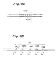
- A method for identifying an optical line, comprising the steps of:forming a plurality of reflecting parts on an optical line along a longitudinal direction thereof; andidentifying the optical line based on a combination of information in the light coming back from the reflecting parts.
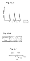
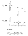
- A method for identifying an optical line according to claim 1, comprising the steps of:forming the plurality of the reflecting parts on the each optical line as an identification code, the each optical line having a specific combination of relative positions of the reflecting parts;detecting the relative positions of the reflecting parts based on reflected light when a detecting light is inputted to the optical line; andidentifying the optical line based on a result of the detecting step.
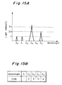
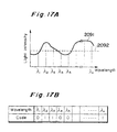
- A method for identifying an optical line according to any one of preceding claims, comprising the steps of:forming the plurality of the reflecting parts on the each optical line as an identification code, the each reflecting part reflecting light having a specific wavelength, and the each optical line having a specific combination of the specific reflecting wavelengths;detecting wavelengths of the reflected light when a detecting light is inputted to optical line; andidentifying the optical line based on a result of the detecting step.
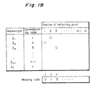
- A method for identifying an optical line according to any one of preceding claims, comprising the steps of:forming the plurality of the reflecting parts on the each optical line as an identification code, the each reflecting part reflecting light having a specific wavelength, and the each optical line having a specific combination of the specific reflecting wavelengths and reflectance;detecting wavelengths and reflectance of the reflected light when a detecting light is inputted to optical line; andidentifying the optical line based on a result of the detecting step.
- A method for identifying an optical line according to any one of preceding claims, comprising the steps of:forming the plurality of the reflecting parts on the each optical line as an identification code, the each reflecting part reflecting light having a specific wavelength, and the each optical line having a specific combination of the specific reflecting wavelengths and relative positions;detecting wavelengths and relative positions of the reflected light when a detecting light is inputted to optical line; andidentifying the optical line based on a result of the detecting step.
- A method for identifying an optical line according to any one of preceding claims, comprising the steps of:forming the reflecting part on the each optical line as an identification code, the reflecting part on the each optical line having a specific reflectance characteristic depending on a wavelength;detecting reflected light spectra coming back from reflecting part when a detecting light is inputted to the optical line; andidentifying the optical line based on a result of the detecting step.
- A method for identifying an optical line according to any one of preceding claims, wherein said plural reflecting parts are provided on each branch optical line.
- A method for identifying an optical line according to any one of preceding claims, characterized by:
detecting the information of the reflected light coming back from the reflecting part at a timing in dependence on the position thereof when a pulsed detecting light is inputted to the optical line. - A method for identification of an optical line according to any one of preceding claims, characterized in that:
the reflecting part consists of striped pattern is formed by varying the refractive index of the optical line or branch optical line locally. - A method for identification of an optical line according to any one of preceding claims, characterized in that:
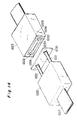
the reflecting part is an optical filter inserted into the optical line or branch optical line. - A method for identification of an optical line according to any one of preceding claims, characterized in that:the optical line consists of a plurality of divided optical fibers,a connecting part with an optical connector is provided between the divided optical lines, andan optical filter as the reflecting part is formed at the optical connector.
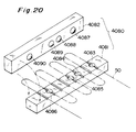
- A method for identifying a multi-core optical line consisting of a bundle of core optical lines, comprising the steps of:forming a plurality of reflecting parts on the multi-core optical line thereof selectively as an identification code,said multi-core optical line having a specific combination of existences of the reflecting parts and characteristics of reflections,detecting the light coming back from said reflected parts when detecting light is inputted to the multi-core optical line;identifying the multi-core optical line based on a result of the detecting step.
- A method for identification of an optical line according to any one of claims 1 to 12, characterized in that:
an optical-path difference of the reflected light from the reflecting parts is measured by an interferometer, and the relative positions of the reflecting parts are detected based on a result of the measurement. - A method for identifying an optical line, comprising the steps of:forming a plurality of bending loss parts on an optical line as an identification code along a longitudinal direction thereof, the bending loss parts having a specific combination of relative positions;detecting the relative positions of the plurality of bending loss parts on the basis of light backscattered from said plurality of bending loss parts when a detecting light is inputted to the optical line; andidentifying the optical line based on a result of the detecting step.
- A method according to claims 1 to 13, wherein said reflecting parts are formed respectively as a diffraction grating (2064) on an optical line (50), comprising the steps of:preparing an optical line (50);irradiating a light (2062) on said optical line (50) through a hologram pattern (2061) so as to project diffractive light caused by said hologram pattern on said optical line (50), thereby forming areas (2064) of which refractive index corresponds to an intensity of said refractive light to be projected on said optical line (50).
- A method according to claim 15, wherein said light irradiated on said hologram pattern is an ultraviolet ray.
- A method according to claim 15 or 16, wherein said optical line (50) comprises an optical fiber.
- An optical line having formed a plurality of reflecting parts along a longitudinal direction thereof for identifying the optical line based on a combination of information in the light coming back from the reflecting parts.
- An optical line (50) according to claim 18 having at least one diffraction grating area as said reflecting part, said diffraction grating area (2064) being formed by irradiating light through a hologram pattern (2061) so as to project a diffractive light (2063) caused by said hologram pattern on the optical line (50), a refractive index of said diffraction grating area corresponding to an intensity of said diffractive light.
- A method according to claims 1 to 13, wherein said reflecting parts are formed respectively as a diffraction grating on an optical line (50), comprising the steps of:preparing an optical line (50); andirradiating a light (2072) on a mask pattern (2071), including magnifying (2073) a light pattern passing through said mask pattern using an optical system (2073), thereby projecting said magnified light pattern on said optical line, wherein a refractive index of the area (2074) corresponds to an intensity of said light pattern passing through said mask pattern (2071).
- A method according to claim 20, wherein said optical system (2073) used in said magnifying step comprises a lens (2073).
- A method according to claim 20, wherein said light irradiated on said mask pattern (2071) is an ultraviolet ray.
- A method according to claim 20, wherein said optical line (50) comprises an optical fiber.
- An optical line according to claim 18 having at least one diffraction grating area as said reflecting part, said diffraction grating area being formed by irradiating light(2072) on a mask pattern (2071) to magnify (2073) a light pattern passing through said mask pattern (2071) with an optical system (2073), thereby projecting a magnified light pattern on said optical line (50), wherein a refractive index of said diffraction grating area (2074) corresponds to an intensity of said light pattern passing through said mask pattern (2071).
- A method according to claims 1 to 13, wherein said reflecting parts are formed respectively as a diffraction grating on an optical line (50), comprising the steps of:preparing an optical line (50);irradiating light (2083) through a slit (2081) to project a slit image on said optical line with changing an intensity of said light being irradiated according to a function of projection position of said slit image in a longitudinal direction (2084) of said optical line to form an area having a refractive index which is different from that of surroundings thereof.
- A method according to claim 25, wherein said light irradiated through said slit (2081) is an ultraviolet ray.
- A method according to claim 25, wherein said optical line comprises an optical fiber.
- A method according to claim 25, wherein said grating is formed by the combination of intensity control of UV light and moving control of the slit.
- An optical line according to claim 18 having at least one diffraction grating area as said reflecting part, said diffraction grating area being formed by irradiating a light (2083) through a slit (2081) so as to project a slit image on the optical line changing an intensity of said light being irradiated according to a function of projection position of said slit image along a longitudinal direction (2084) of the optical line, thereby forming an area having a refractive index which is different from that of surroundings thereof.
- An optical line according to claim 19, wherein a plurality of diffraction grating areas are provided on the optical line and are arranged along a longitudinal direction of the optical line, whereby the optical line is identifiable to at least one characteristic of light reflected by said plurality of diffraction grating areas in response to light supplied to an end of the optical line.
- An optical line according to claim 24, wherein a plurality of diffraction grating areas are provided on the optical line and are arranged along a longitudinal direction, the optical line being identifiable to at least one characteristic of light reflected by said plurality of diffraction grating areas in response to light supplied to an end of the optical line.
- An optical line according to claim 29, wherein a plurality of diffraction grating areas are provided on the optical line and are arranged along a longitudinal direction, the optical line being identifiable according to at least one characteristic of light reflected by said diffraction grating areas in response to light supplied to one end of the optical fiber.
- A method according to claim 12, characterized in that said plurality of reflecting parts are formed on said multicore optical line along a longitudinal direction thereof.
Priority Applications (1)
| Application Number | Priority Date | Filing Date | Title |
|---|---|---|---|
| EP98102083A EP0851248B1 (en) | 1992-05-01 | 1993-04-28 | Method for identifying optical line |
Applications Claiming Priority (15)
| Application Number | Priority Date | Filing Date | Title |
|---|---|---|---|
| JP112808/92 | 1992-05-01 | ||
| JP112804/92 | 1992-05-01 | ||
| JP112797/92 | 1992-05-01 | ||
| JP112820/92 | 1992-05-01 | ||
| JP4112797A JPH05307118A (en) | 1992-05-01 | 1992-05-01 | Method for identifying optical path |
| JP04112805A JP3078104B2 (en) | 1992-05-01 | 1992-05-01 | Optical line identification method |
| JP4112820A JPH05313020A (en) | 1992-05-01 | 1992-05-01 | Light path identifying method |
| JP112822/92 | 1992-05-01 | ||
| JP04112818A JP3078105B2 (en) | 1992-05-01 | 1992-05-01 | Optical line identification method |
| JP04112804A JP3078103B2 (en) | 1992-05-01 | 1992-05-01 | Optical line identification method |
| JP112818/92 | 1992-05-01 | ||
| JP04112808A JP3129831B2 (en) | 1992-05-01 | 1992-05-01 | Optical line identification method |
| JP04112822A JP3078106B2 (en) | 1992-05-01 | 1992-05-01 | Optical line identification method |
| JP112805/92 | 1992-05-01 | ||
| PCT/JP1993/000567 WO1993022647A1 (en) | 1992-05-01 | 1993-04-28 | Method for identifying optical line |
Related Child Applications (1)
| Application Number | Title | Priority Date | Filing Date |
|---|---|---|---|
| EP98102083A Division EP0851248B1 (en) | 1992-05-01 | 1993-04-28 | Method for identifying optical line |
Publications (3)
| Publication Number | Publication Date |
|---|---|
| EP0592690A1 EP0592690A1 (en) | 1994-04-20 |
| EP0592690A4 EP0592690A4 (en) | 1995-03-15 |
| EP0592690B1 true EP0592690B1 (en) | 1998-10-14 |
Family
ID=27565796
Family Applications (2)
| Application Number | Title | Priority Date | Filing Date |
|---|---|---|---|
| EP98102083A Expired - Lifetime EP0851248B1 (en) | 1992-05-01 | 1993-04-28 | Method for identifying optical line |
| EP93911952A Expired - Lifetime EP0592690B1 (en) | 1992-05-01 | 1993-04-28 | Method for identifying optical line |
Family Applications Before (1)
| Application Number | Title | Priority Date | Filing Date |
|---|---|---|---|
| EP98102083A Expired - Lifetime EP0851248B1 (en) | 1992-05-01 | 1993-04-28 | Method for identifying optical line |
Country Status (9)
| Country | Link |
|---|---|
| US (2) | US5506674A (en) |
| EP (2) | EP0851248B1 (en) |
| KR (2) | KR970004993B1 (en) |
| CN (2) | CN1238980C (en) |
| AU (1) | AU666382B2 (en) |
| CA (1) | CA2112692C (en) |
| DE (2) | DE69333369T2 (en) |
| NO (1) | NO318903B1 (en) |
| WO (1) | WO1993022647A1 (en) |
Cited By (3)
| Publication number | Priority date | Publication date | Assignee | Title |
|---|---|---|---|---|
| GB2280326B (en) * | 1993-07-15 | 1997-04-23 | Marconi Gec Ltd | Optical communication systems |
| FR2865044A1 (en) * | 2004-01-14 | 2005-07-15 | Cit Alcatel | Optical fiber, for use in optical cable, has pattern that corresponds to information related to fiber's technical characteristics to permit fiber type's identification and that is cut in protection layer using ablation via lasers |
| US7974182B2 (en) | 2004-03-31 | 2011-07-05 | British Telecommunications Public Limited Company | Evaluating the position of a disturbance |
Families Citing this family (79)
| Publication number | Priority date | Publication date | Assignee | Title |
|---|---|---|---|---|
| GB9506163D0 (en) * | 1995-03-27 | 1995-05-17 | Bicc Plc | Optical fibre and network |
| GB9515498D0 (en) * | 1995-07-28 | 1995-09-27 | Bicc Plc | Optical fibre system |
| JP2924881B2 (en) * | 1997-01-27 | 1999-07-26 | 住友電気工業株式会社 | Tunable light source and OTDR device |
| US5898804A (en) * | 1997-06-09 | 1999-04-27 | Trw Inc. | Precision wavelength control for automated fiber optic Bragg grating writing |
| JP3414257B2 (en) * | 1998-05-19 | 2003-06-09 | 安藤電気株式会社 | Multi-core optical fiber measurement data summarizing method and apparatus, and recording medium recording summarization processing program |
| US6157443A (en) * | 1998-08-19 | 2000-12-05 | Lucent Technologies Inc. | Method and system for transporting data for monitoring optical fibers |
| US20050074244A1 (en) * | 2000-01-12 | 2005-04-07 | Nortel Networks Limited | Optimization of a communications system based on identification of an optical member |
| US6347172B1 (en) | 2000-06-28 | 2002-02-12 | Alcatel | Cable having side-emitting fiber under transparent or translucent cable jacket |
| US6643436B2 (en) * | 2000-12-14 | 2003-11-04 | Radiodetection Limited | Identifying fibers of fiber optic cables |
| US7399643B2 (en) * | 2002-09-12 | 2008-07-15 | Cyvera Corporation | Method and apparatus for aligning microbeads in order to interrogate the same |
| AU2003265583C1 (en) * | 2002-08-20 | 2009-05-21 | Cyvera Corporation | Diffraction grating-based optical identification element |
| US20050227252A1 (en) * | 2002-08-20 | 2005-10-13 | Moon John A | Diffraction grating-based encoded articles for multiplexed experiments |
| US7164533B2 (en) | 2003-01-22 | 2007-01-16 | Cyvera Corporation | Hybrid random bead/chip based microarray |
| WO2004019277A1 (en) * | 2002-08-20 | 2004-03-04 | Cyvera Corporation | Diffraction grating-based encoded micro-particles for multiplexed experiments |
| US7872804B2 (en) * | 2002-08-20 | 2011-01-18 | Illumina, Inc. | Encoded particle having a grating with variations in the refractive index |
| US7508608B2 (en) | 2004-11-17 | 2009-03-24 | Illumina, Inc. | Lithographically fabricated holographic optical identification element |
| US7923260B2 (en) | 2002-08-20 | 2011-04-12 | Illumina, Inc. | Method of reading encoded particles |
| US7901630B2 (en) | 2002-08-20 | 2011-03-08 | Illumina, Inc. | Diffraction grating-based encoded microparticle assay stick |
| US7441703B2 (en) * | 2002-08-20 | 2008-10-28 | Illumina, Inc. | Optical reader for diffraction grating-based encoded optical identification elements |
| US7900836B2 (en) | 2002-08-20 | 2011-03-08 | Illumina, Inc. | Optical reader system for substrates having an optically readable code |
| EP1540588A1 (en) * | 2002-09-12 | 2005-06-15 | Cyvera Corporation | Diffraction grating-based optical identification element |
| AU2003270726A1 (en) * | 2002-09-12 | 2004-04-30 | Cidra Corporation | Diffraction grating-based encoded micro-particles for multiplexed experiments |
| US20100255603A9 (en) | 2002-09-12 | 2010-10-07 | Putnam Martin A | Method and apparatus for aligning microbeads in order to interrogate the same |
| EP1540592A1 (en) * | 2002-09-12 | 2005-06-15 | Cyvera Corporation | Method and apparatus for labeling using diffraction grating-based encoded optical identification elements |
| CA2498913A1 (en) * | 2002-09-12 | 2004-03-25 | Cyvera Corporation | Assay stick comprising coded microbeads |
| CA2498916A1 (en) * | 2002-09-12 | 2004-03-25 | Cyvera Corporation | Chemical synthesis using diffraction grating-based encoded optical elements |
| US7092160B2 (en) | 2002-09-12 | 2006-08-15 | Illumina, Inc. | Method of manufacturing of diffraction grating-based optical identification element |
| WO2004066210A1 (en) * | 2003-01-22 | 2004-08-05 | Cyvera Corporation | Hybrid random bead/chip based microarray |
| US20060057729A1 (en) * | 2003-09-12 | 2006-03-16 | Illumina, Inc. | Diffraction grating-based encoded element having a substance disposed thereon |
| WO2005027031A2 (en) * | 2003-09-12 | 2005-03-24 | Cyvera Corporation | Method and apparatus for labeling using diffraction grating-based encoded optical identification elements |
| EP1671165A4 (en) * | 2003-09-25 | 2007-07-04 | Redfern Optical Components Pty | A method of optical data storage |
| GB0322859D0 (en) | 2003-09-30 | 2003-10-29 | British Telecomm | Communication |
| US7667849B2 (en) | 2003-09-30 | 2010-02-23 | British Telecommunications Public Limited Company | Optical sensor with interferometer for sensing external physical disturbance of optical communications link |
| US7433123B2 (en) * | 2004-02-19 | 2008-10-07 | Illumina, Inc. | Optical identification element having non-waveguide photosensitive substrate with diffraction grating therein |
| WO2006020363A2 (en) | 2004-07-21 | 2006-02-23 | Illumina, Inc. | Method and apparatus for drug product tracking using encoded optical identification elements |
| US7848645B2 (en) | 2004-09-30 | 2010-12-07 | British Telecommunications Public Limited Company | Identifying or locating waveguides |
| GB0421747D0 (en) | 2004-09-30 | 2004-11-03 | British Telecomm | Distributed backscattering |
| DE602005019791D1 (en) | 2004-11-16 | 2010-04-15 | Illumina Inc | METHOD AND DEVICE FOR READING CODED MICROBALLS |
| WO2006055735A2 (en) * | 2004-11-16 | 2006-05-26 | Illumina, Inc | Scanner having spatial light modulator |
| US7604173B2 (en) * | 2004-11-16 | 2009-10-20 | Illumina, Inc. | Holographically encoded elements for microarray and other tagging labeling applications, and method and apparatus for making and reading the same |
| JP4782798B2 (en) | 2004-12-17 | 2011-09-28 | ブリティッシュ・テレコミュニケーションズ・パブリック・リミテッド・カンパニー | Network evaluation |
| GB0427733D0 (en) | 2004-12-17 | 2005-01-19 | British Telecomm | Optical system |
| DE102005006318A1 (en) * | 2005-02-11 | 2006-08-17 | Deutsche Telekom Ag | Unique marking of glass fibers |
| ATE434774T1 (en) | 2005-03-04 | 2009-07-15 | British Telecomm | ACOUSTOPTICAL MODULATOR ARRANGEMENT |
| GB0504579D0 (en) | 2005-03-04 | 2005-04-13 | British Telecomm | Communications system |
| EP1708388A1 (en) | 2005-03-31 | 2006-10-04 | British Telecommunications Public Limited Company | Communicating information |
| EP1713301A1 (en) | 2005-04-14 | 2006-10-18 | BRITISH TELECOMMUNICATIONS public limited company | Method and apparatus for communicating sound over an optical link |
| CA2610375A1 (en) * | 2005-05-23 | 2006-11-30 | Lxsix Photonics Inc. | Methods and apparatuses for obtaining information regarding sensors in optical paths |
| EP1729096A1 (en) | 2005-06-02 | 2006-12-06 | BRITISH TELECOMMUNICATIONS public limited company | Method and apparatus for determining the position of a disturbance in an optical fibre |
| EP1757966A3 (en) | 2005-08-23 | 2007-12-19 | KT Corporation | Apparatus and method for identification of optical cable |
| US8482725B2 (en) * | 2005-10-24 | 2013-07-09 | Exfo Inc. | Method and apparatus for identification of multiple fibers using an OTDR |
| EP1952561B1 (en) * | 2005-10-24 | 2018-04-04 | Exfo Inc. | Method and apparatus for identification of multiple fibers using an otdr |
| US7623624B2 (en) * | 2005-11-22 | 2009-11-24 | Illumina, Inc. | Method and apparatus for labeling using optical identification elements characterized by X-ray diffraction |
| EP1989797B1 (en) | 2006-02-24 | 2011-04-13 | BRITISH TELECOMMUNICATIONS public limited company | Sensing a disturbance |
| CA2643345A1 (en) | 2006-02-24 | 2007-08-30 | British Telecommunications Public Limited Company | Sensing a disturbance |
| EP1826924A1 (en) | 2006-02-24 | 2007-08-29 | BRITISH TELECOMMUNICATIONS public limited company | Sensing a disturbance |
| CA2647173A1 (en) | 2006-04-03 | 2007-10-11 | British Telecommunications Public Company Limited | Evaluating the position of a disturbance |
| US7830575B2 (en) | 2006-04-10 | 2010-11-09 | Illumina, Inc. | Optical scanner with improved scan time |
| WO2008116309A1 (en) * | 2007-03-26 | 2008-10-02 | Universite Laval | Method and system for testing for defects in a multipath optical network |
| KR100888917B1 (en) * | 2007-04-09 | 2009-03-16 | 주식회사 파이버프로 | Identification apparatus of optical cable and identification method |
| WO2008154485A1 (en) * | 2007-06-07 | 2008-12-18 | Afl Telecommunications Llc | Method for detecting fiber optic fibers and ribbons |
| DE102009018478A1 (en) * | 2009-04-22 | 2010-11-18 | Adc Gmbh | Method and arrangement for identifying at least one object |
| CN102104421B (en) * | 2009-12-16 | 2015-03-25 | 华为技术有限公司 | Branched optical fiber failure detection method and device for optical network, and optical network |
| CN102244539B (en) * | 2010-05-11 | 2014-09-17 | 华为技术有限公司 | Method and system for detecting branch optical fibers, PON (passive optical network) and optical splitter |
| US20130183035A1 (en) * | 2011-12-01 | 2013-07-18 | Joseph L. Smith | Enhanced PON And Splitter Module And Associated Method |
| US10026030B2 (en) * | 2012-01-13 | 2018-07-17 | Empire Technology Development Llc | Simple diffraction gratings for product identification |
| CN104220846A (en) * | 2012-03-23 | 2014-12-17 | 住友电气工业株式会社 | Interference measuring apparatus |
| CH706936B1 (en) * | 2012-09-14 | 2016-04-15 | Diamond Sa | A method for creating a fiber optic link and using a splicer in such a process. |
| ES2620292T3 (en) * | 2012-11-28 | 2017-06-28 | Deutsche Telekom Ag | Data network |
| US9184833B2 (en) * | 2013-08-28 | 2015-11-10 | Fluke Corporation | Optical fiber testing using OTDR instrument |
| CN104729831B (en) * | 2015-01-23 | 2017-11-21 | 湖南新中合光电科技股份有限公司 | A kind of FA light leakage detecting devices |
| DE102016124654A1 (en) * | 2016-12-16 | 2018-06-21 | fos4X GmbH | Method and apparatus for identifying a fiber in a bundle of optical fibers and related use |
| US20200400276A1 (en) * | 2017-02-16 | 2020-12-24 | Ficomms Limited | Conduit identifying method and apparatus |
| US11047766B2 (en) | 2018-04-11 | 2021-06-29 | Afl Telecommunications Llc | Systems and methods for identification and testing of optical fibers |
| CN108833001A (en) * | 2018-04-18 | 2018-11-16 | 中山水木光华电子信息科技有限公司 | A kind of optical fiber code identifying system based on tunable optical source |
| CN111198169A (en) * | 2019-11-08 | 2020-05-26 | 桂林电子科技大学 | Microstructure optical fiber high resolution three-dimensional refractive index testing method |
| JP2022167095A (en) * | 2021-04-22 | 2022-11-04 | 横河電機株式会社 | optical pulse tester |
| WO2023274530A1 (en) * | 2021-06-30 | 2023-01-05 | Telefonaktiebolaget Lm Ericsson (Publ) | A method for determining information associated with an optical component system |
| US20230384126A1 (en) * | 2022-05-27 | 2023-11-30 | Kidde Technologies, Inc. | Digital data encoding in optical fibers using fiber bragg gratings |
Family Cites Families (23)
| Publication number | Priority date | Publication date | Assignee | Title |
|---|---|---|---|---|
| US3689264A (en) * | 1970-03-19 | 1972-09-05 | Bell Telephone Labor Inc | Method for increasing index of refraction in transparent bodies and its application to light guides and the like |
| BE789176A (en) * | 1971-09-24 | 1973-01-15 | Siemens Ag | DEVICE FOR THE INTRODUCTION AND EXTRACTION OF LIGHT IN DIELECTRIC OPTICAL WAVE GUIDES AND PROCESS FOR ITS MANUFACTURING |
| WO1986001303A1 (en) * | 1984-08-13 | 1986-02-27 | United Technologies Corporation | Method for impressing grating within fiber optics |
| GB8722615D0 (en) * | 1987-09-25 | 1987-11-04 | Plessey Co Plc | Optical fibres |
| JPH0786572B2 (en) * | 1988-07-08 | 1995-09-20 | 株式会社関西テレコムテクノロジー | Optical fiber cable empty line identification method |
| WO1990004803A1 (en) * | 1988-10-24 | 1990-05-03 | Australian Optical Fibre Research Pty Limited | Optical switch |
| JP2721211B2 (en) * | 1988-11-24 | 1998-03-04 | 古河電気工業株式会社 | Branch optical line loss distribution measurement device |
| GB8828408D0 (en) * | 1988-12-06 | 1989-01-05 | British Telecomm | Loss detector |
| JP2676090B2 (en) * | 1989-01-05 | 1997-11-12 | 株式会社フジクラ | Optical fiber core wire contrast method |
| US5098804A (en) * | 1989-01-13 | 1992-03-24 | E. I. Du Pont De Nemours And Company | Multiplexer-demultiplexer for integrated optic circuit |
| EP0380801A3 (en) * | 1989-02-01 | 1991-11-06 | Leningradskoe Otdelenie Tsentralnogo Nauchno-Issledo-Vatelskogo Instituta Svyazi (Loniis) | Process for determining the optical loss of optical fibres in reflected light |
| EP0380779A3 (en) * | 1989-02-01 | 1991-10-30 | Leningradskoe Otdelenie Tsentralnogo Nauchno-Issledo-Vatelskogo Instituta Svyazi (Loniis) | Method for determining the optical losses of optical fibres by reflected light |
| EP0380800A3 (en) * | 1989-02-01 | 1991-10-30 | Leningradskoe Otdelenie Tsentralnogo Nauchno-Issledo-Vatelskogo Instituta Svyazi (Loniis) | Process for determining the optical loss of coupled optical fibres in reflected light |
| EP0380981A3 (en) * | 1989-02-01 | 1991-10-30 | Leningradskoe Otdelenie Tsentralnogo Nauchno-Issledo-Vatelskogo Instituta Svyazi (Loniis) | Process for determining the optical loss at the ends and connection ends of optical fibres |
| JP2566004B2 (en) * | 1989-03-02 | 1996-12-25 | 古河電気工業株式会社 | Optical fiber cable identification method and its identification device |
| JPH02230105A (en) * | 1989-03-02 | 1990-09-12 | Furukawa Electric Co Ltd:The | Method and device for identifying optical fiber cable |
| GB8918862D0 (en) * | 1989-08-18 | 1989-09-27 | British Telecomm | Line monitoring system |
| GB9007897D0 (en) * | 1990-04-06 | 1990-06-06 | British Telecomm | Method of controlling the transmission characteristics of an optical communications network |
| JP2874977B2 (en) * | 1990-07-27 | 1999-03-24 | 日本電信電話株式会社 | Fiber identification method for distribution type optical line |
| GB9022969D0 (en) * | 1990-10-23 | 1990-12-05 | Rosemount Ltd | Displacement measurement apparatus |
| US5104209A (en) * | 1991-02-19 | 1992-04-14 | Her Majesty The Queen In Right Of Canada, As Represented By The Minister Of Communications | Method of creating an index grating in an optical fiber and a mode converter using the index grating |
| US5367588A (en) * | 1992-10-29 | 1994-11-22 | Her Majesty The Queen In Right Of Canada, As Represented By The Minister Of Communications | Method of fabricating Bragg gratings using a silica glass phase grating mask and mask used by same |
| US5604829A (en) * | 1995-04-17 | 1997-02-18 | Hughes Aircraft Company | Optical waveguide with diffraction grating and method of forming the same |
-
1993
- 1993-04-28 CA CA002112692A patent/CA2112692C/en not_active Expired - Lifetime
- 1993-04-28 EP EP98102083A patent/EP0851248B1/en not_active Expired - Lifetime
- 1993-04-28 DE DE69333369T patent/DE69333369T2/en not_active Expired - Lifetime
- 1993-04-28 DE DE69321548T patent/DE69321548T2/en not_active Expired - Lifetime
- 1993-04-28 US US08/170,297 patent/US5506674A/en not_active Expired - Lifetime
- 1993-04-28 AU AU42713/93A patent/AU666382B2/en not_active Ceased
- 1993-04-28 KR KR1019930704090A patent/KR970004993B1/en not_active IP Right Cessation
- 1993-04-28 EP EP93911952A patent/EP0592690B1/en not_active Expired - Lifetime
- 1993-04-28 WO PCT/JP1993/000567 patent/WO1993022647A1/en active IP Right Grant
- 1993-05-01 CN CNB991024729A patent/CN1238980C/en not_active Expired - Fee Related
- 1993-05-01 CN CN93106370A patent/CN1045663C/en not_active Expired - Fee Related
- 1993-12-30 NO NO19934917A patent/NO318903B1/en not_active IP Right Cessation
-
1996
- 1996-01-19 US US08/605,265 patent/US5671308A/en not_active Expired - Lifetime
-
1997
- 1997-02-17 KR KR97701034A patent/KR0148255B1/en not_active IP Right Cessation
Cited By (3)
| Publication number | Priority date | Publication date | Assignee | Title |
|---|---|---|---|---|
| GB2280326B (en) * | 1993-07-15 | 1997-04-23 | Marconi Gec Ltd | Optical communication systems |
| FR2865044A1 (en) * | 2004-01-14 | 2005-07-15 | Cit Alcatel | Optical fiber, for use in optical cable, has pattern that corresponds to information related to fiber's technical characteristics to permit fiber type's identification and that is cut in protection layer using ablation via lasers |
| US7974182B2 (en) | 2004-03-31 | 2011-07-05 | British Telecommunications Public Limited Company | Evaluating the position of a disturbance |
Also Published As
| Publication number | Publication date |
|---|---|
| EP0851248A3 (en) | 2000-01-26 |
| CN1249576A (en) | 2000-04-05 |
| EP0592690A1 (en) | 1994-04-20 |
| KR970004993B1 (en) | 1997-04-10 |
| EP0851248B1 (en) | 2003-12-17 |
| CN1082717A (en) | 1994-02-23 |
| AU4271393A (en) | 1993-11-29 |
| DE69333369T2 (en) | 2004-10-07 |
| EP0592690A4 (en) | 1995-03-15 |
| AU666382B2 (en) | 1996-02-08 |
| US5506674A (en) | 1996-04-09 |
| KR940701538A (en) | 1994-05-28 |
| DE69333369D1 (en) | 2004-01-29 |
| US5671308A (en) | 1997-09-23 |
| CA2112692A1 (en) | 1993-11-02 |
| EP0851248A2 (en) | 1998-07-01 |
| NO934917L (en) | 1994-02-24 |
| CN1045663C (en) | 1999-10-13 |
| KR0148255B1 (en) | 1998-08-17 |
| WO1993022647A1 (en) | 1993-11-11 |
| DE69321548T2 (en) | 1999-04-15 |
| CA2112692C (en) | 2004-09-21 |
| DE69321548D1 (en) | 1998-11-19 |
| CN1238980C (en) | 2006-01-25 |
| NO934917D0 (en) | 1993-12-30 |
| NO318903B1 (en) | 2005-05-18 |
Similar Documents
| Publication | Publication Date | Title |
|---|---|---|
| EP0592690B1 (en) | Method for identifying optical line | |
| CN107063127B (en) | Optical measuring device | |
| CA2272033A1 (en) | Arrangement for determining the temperature and strain of an optical fiber | |
| US5862285A (en) | Multichannel optical fiber bundle with ordered structure in its sensitive probe tip | |
| JPH0827212B2 (en) | Spectroscope | |
| JPH07503544A (en) | Measuring device for light waveguides and method of carrying out this measurement | |
| JPH0943432A (en) | Optical line having identification marker | |
| JP3078103B2 (en) | Optical line identification method | |
| CA2449305A1 (en) | Optical waveguide having a diffraction grating area and method of fabricating the same | |
| EP3786606A1 (en) | Parallel optics based optical time domain reflectometer acquisition | |
| JP3078104B2 (en) | Optical line identification method | |
| JPH10160635A (en) | Skew inspection method of multifiber optical fiber tape and skew measurement device | |
| JP3078105B2 (en) | Optical line identification method | |
| JP3231238B2 (en) | Optical fiber and method of manufacturing optical fiber type diffraction grating | |
| JP3231167B2 (en) | Optical line identification method and optical line identification device | |
| JPH05307118A (en) | Method for identifying optical path | |
| JP3078106B2 (en) | Optical line identification method | |
| JP3129831B2 (en) | Optical line identification method | |
| JP3303271B2 (en) | Optical fiber contrast method of branch optical line | |
| JPH06347649A (en) | Method for identifying optical path | |
| JP3215774B2 (en) | Optical line identification method | |
| Fukushima et al. | A 7/spl times/6 optical fiber grating demultiplexer-multiposition switch for 0.64-0.88/spl mu/m band | |
| Boye et al. | Application of resonant subwavelength gratings to a rotary position encoder | |
| JPH05164654A (en) | Method and device for monitoring optical fiber light loss | |
| Bussard et al. | Optical design and experimental results of a six-channel LED Littrow-type wavelength-division-multiplexing coupler |
Legal Events
| Date | Code | Title | Description |
|---|---|---|---|
| PUAI | Public reference made under article 153(3) epc to a published international application that has entered the european phase |
Free format text: ORIGINAL CODE: 0009012 |
|
| AK | Designated contracting states |
Kind code of ref document: A1 Designated state(s): DE FR GB IT SE |
|
| 17P | Request for examination filed |
Effective date: 19940408 |
|
| A4 | Supplementary search report drawn up and despatched | ||
| AK | Designated contracting states |
Kind code of ref document: A4 Designated state(s): DE FR GB IT SE |
|
| 17Q | First examination report despatched |
Effective date: 19960417 |
|
| GRAG | Despatch of communication of intention to grant |
Free format text: ORIGINAL CODE: EPIDOS AGRA |
|
| GRAG | Despatch of communication of intention to grant |
Free format text: ORIGINAL CODE: EPIDOS AGRA |
|
| GRAH | Despatch of communication of intention to grant a patent |
Free format text: ORIGINAL CODE: EPIDOS IGRA |
|
| GRAH | Despatch of communication of intention to grant a patent |
Free format text: ORIGINAL CODE: EPIDOS IGRA |
|
| GRAA | (expected) grant |
Free format text: ORIGINAL CODE: 0009210 |
|
| AK | Designated contracting states |
Kind code of ref document: B1 Designated state(s): DE FR GB IT SE |
|
| REF | Corresponds to: |
Ref document number: 69321548 Country of ref document: DE Date of ref document: 19981119 |
|
| ET | Fr: translation filed | ||
| PLBE | No opposition filed within time limit |
Free format text: ORIGINAL CODE: 0009261 |
|
| STAA | Information on the status of an ep patent application or granted ep patent |
Free format text: STATUS: NO OPPOSITION FILED WITHIN TIME LIMIT |
|
| 26N | No opposition filed | ||
| REG | Reference to a national code |
Ref country code: GB Ref legal event code: IF02 |
|
| PGFP | Annual fee paid to national office [announced via postgrant information from national office to epo] |
Ref country code: FR Payment date: 20110426 Year of fee payment: 19 Ref country code: DE Payment date: 20110420 Year of fee payment: 19 Ref country code: SE Payment date: 20110412 Year of fee payment: 19 |
|
| PGFP | Annual fee paid to national office [announced via postgrant information from national office to epo] |
Ref country code: GB Payment date: 20110427 Year of fee payment: 19 |
|
| PGFP | Annual fee paid to national office [announced via postgrant information from national office to epo] |
Ref country code: IT Payment date: 20110412 Year of fee payment: 19 |
|
| REG | Reference to a national code |
Ref country code: SE Ref legal event code: EUG |
|
| GBPC | Gb: european patent ceased through non-payment of renewal fee |
Effective date: 20120428 |
|
| REG | Reference to a national code |
Ref country code: FR Ref legal event code: ST Effective date: 20121228 |
|
| PG25 | Lapsed in a contracting state [announced via postgrant information from national office to epo] |
Ref country code: GB Free format text: LAPSE BECAUSE OF NON-PAYMENT OF DUE FEES Effective date: 20120428 |
|
| REG | Reference to a national code |
Ref country code: DE Ref legal event code: R119 Ref document number: 69321548 Country of ref document: DE Effective date: 20121101 |
|
| PG25 | Lapsed in a contracting state [announced via postgrant information from national office to epo] |
Ref country code: FR Free format text: LAPSE BECAUSE OF NON-PAYMENT OF DUE FEES Effective date: 20120430 Ref country code: IT Free format text: LAPSE BECAUSE OF NON-PAYMENT OF DUE FEES Effective date: 20120428 Ref country code: SE Free format text: LAPSE BECAUSE OF NON-PAYMENT OF DUE FEES Effective date: 20120429 |
|
| PG25 | Lapsed in a contracting state [announced via postgrant information from national office to epo] |
Ref country code: DE Free format text: LAPSE BECAUSE OF NON-PAYMENT OF DUE FEES Effective date: 20121101 |