EP0585908A2 - Container with insertable bag - Google Patents
Container with insertable bag Download PDFInfo
- Publication number
- EP0585908A2 EP0585908A2 EP93114001A EP93114001A EP0585908A2 EP 0585908 A2 EP0585908 A2 EP 0585908A2 EP 93114001 A EP93114001 A EP 93114001A EP 93114001 A EP93114001 A EP 93114001A EP 0585908 A2 EP0585908 A2 EP 0585908A2
- Authority
- EP
- European Patent Office
- Prior art keywords
- immersion tube
- container
- bag
- collapsible
- valve body
- Prior art date
- Legal status (The legal status is an assumption and is not a legal conclusion. Google has not performed a legal analysis and makes no representation as to the accuracy of the status listed.)
- Withdrawn
Links
Images


Classifications
-
- B—PERFORMING OPERATIONS; TRANSPORTING
- B65—CONVEYING; PACKING; STORING; HANDLING THIN OR FILAMENTARY MATERIAL
- B65D—CONTAINERS FOR STORAGE OR TRANSPORT OF ARTICLES OR MATERIALS, e.g. BAGS, BARRELS, BOTTLES, BOXES, CANS, CARTONS, CRATES, DRUMS, JARS, TANKS, HOPPERS, FORWARDING CONTAINERS; ACCESSORIES, CLOSURES, OR FITTINGS THEREFOR; PACKAGING ELEMENTS; PACKAGES
- B65D83/00—Containers or packages with special means for dispensing contents
- B65D83/14—Containers or packages with special means for dispensing contents for delivery of liquid or semi-liquid contents by internal gaseous pressure, i.e. aerosol containers comprising propellant for a product delivered by a propellant
- B65D83/60—Contents and propellant separated
- B65D83/62—Contents and propellant separated by membrane, bag, or the like
-
- B—PERFORMING OPERATIONS; TRANSPORTING
- B65—CONVEYING; PACKING; STORING; HANDLING THIN OR FILAMENTARY MATERIAL
- B65D—CONTAINERS FOR STORAGE OR TRANSPORT OF ARTICLES OR MATERIALS, e.g. BAGS, BARRELS, BOTTLES, BOXES, CANS, CARTONS, CRATES, DRUMS, JARS, TANKS, HOPPERS, FORWARDING CONTAINERS; ACCESSORIES, CLOSURES, OR FITTINGS THEREFOR; PACKAGING ELEMENTS; PACKAGES
- B65D2231/00—Means for facilitating the complete expelling of the contents
- B65D2231/001—Means for facilitating the complete expelling of the contents the container being a bag
- B65D2231/004—Means for facilitating the complete expelling of the contents the container being a bag comprising rods or tubes provided with radial openings, ribs or the like, e.g. dip-tubes, spiral rods
Definitions
- the present invention relates to barrier bag containers for storing and dispensing a filling material and to a method for producing the same.
- Barrier bag containers with a double chamber system are generally known, but are not yet widespread.
- This type of container contains an inner, compressible container or collapsible bag, which is surrounded by an outer, solid container or jacket. This creates two independent chambers; one inside the compressible inner bag and the other between the outer jacket and the inner bag.
- a closure in the form of a valve or dispenser is placed over the outer casing in such a way that the outer edge of the closure surrounds the upper part of the outer casing and hermetically seals it.
- the valve is connected to the inner, compressible bag so that only the contents of the same can be released to the environment.
- the propellant gas therefore does not come into contact with the contents of the inner, collapsible bag, since this is enclosed in the chamber separated from the outer jacket and the inner bag.
- the known barrier bag containers have a relatively complicated structure and are expensive to produce because special container components and apparatus are required for this.
- the inner, compressible bag in the well-known double chamber containers is made of a solid but very supple material.
- Soft aluminum foils, pliable plastic material or laminated foils such as polyolefins, aluminum foils, nylon and are suitable for this Polyester, which are connected to each other so that a coated or laminated film is formed.
- the material of the inner, compressible bag must be of good quality so that no diffusion and thus mixing of product and blowing agent can occur.
- barrier bag containers One problem with the manufacture of barrier bag containers is the hermetic fixation of the inner, compressible bag to the material of the valve body. There must be no leakage of product and propellant from the two separate chambers. The solution to this problem is made difficult by the requirements for the inner, collapsible bag. The inner compressible bag must not become detached due to the pressure created during filling and during the drop tests during quality control.
- the inner, compressible bag consists of a multilayer laminate which is welded directly to the valve body and which special valve body is made of polyethylene. This material allows the collapsible bag to be welded to the valve body.
- most standardized and commercially available valve bodies for the containers have a valve body made of nylon, while the inner, compressible bag is made of polyolefins or contains polyolefins. So that the collapsible bag can still be welded directly to the valve body, a special valve body is required which is made of a different material than conventional nylon; eg from polyolefins, as already mentioned above. In this form, the inner, compressible bag can be easily welded to the valve body.
- the present invention is to provide an improved barrier bag container which overcomes the problems of the conventional barrier bag container described above compensates or overcomes.
- a special characteristic of the present invention consists in the composition and the method for producing a novel barrier bag container, which allows greater freedom of design for the various possible uses.
- Another characteristic of the invention lies in the simplification in the manufacture and in the use of cheap, standardized, commercially available valves with immersion tubes. There is no need for any special valve configurations or materials, as they were previously used for the production of barrier bag containers.
- the barrier bag container on which the invention is based for storing and dispensing a filling material.
- the container contains an outer jacket and a valve which is attached to the outer jacket of the container.
- the valve of the dispenser contains a manually operable valve button, which can release the product in the bag when actuated.
- An inner, compressible bag is placed within the barrier bag container which contains the product to be released.
- An immersion tube is placed over an annular cone on the valve body and is thereby secured.
- the immersion tube is located inside the collapsible pouch so that the product can be released in the pouch via the immersion tube and valve.
- the inner, compressible bag is attached to the upper part of the immersion tube, which in turn is placed over an annular, cone-like projection, which is located on the valve body.
- the collapsible is easier and less problematic Attach the bag directly to the outer top of the relatively thin dip tube, rather than to a specially designed connector or directly to the valve.
- the attachment is preferably carried out by welding.
- no special welding spindle or welding cores are required to support the interior of the immersion tube during welding, since this function is achieved by the stable, annular cone of the valve is guaranteed, over which the immersion tube is put.
- valves when the bag is sealed with a standardized immersion tube, commercial valves can be used which show a higher degree of flexibility and are also more user-friendly. It also reduces the cost of off-the-shelf valve use and eliminates the need for complex connectors, special valve configurations, and materials that were previously used in the manufacture of barrier bag containers.
- the immersion tube must be firmly connected to the valve before welding, ie one end of the immersion tube is put over the annular cone of the valve.
- the flexible material of the compressible bag is then welded to the part of the immersion tube which has been put over this annular projection of the valve body.
- two vertically opposite welding blocks are used, which can clamp the bag, the immersion tube and the valve cone exactly.
- the underside of the valve with the annular projection already discussed ultimately serves to support the one end of the immersion tube against the pressure of the welding blocks and to achieve problem-free and accurate welding with the supple material of the bag.
- the part of the valve over which the immersion tube is placed has an annular shoulder that forms a kind of cone. Slipping the immersion tube over the cone guarantees a tight fit, so that even when the collapsible container is filled under pressure, the valve and tube are not released.
- the place where the immersion tube with the collapsible container lies above the conical part is kept free, i.e. no weld seam is created because the cone could be damaged by the heat and the tube on it could melt, which would lead to a loss of elasticity. Otherwise there would be a risk that the immersion tube with the welded-on bag could become detached from the valve when filling the container or during drop tests in quality control.
- the inner, compressible bag is only welded to the immersion tube above and below the annular cone and axially to the same. No weld seam is therefore made directly above the annular cone.
- valve and the immersion tube in the arrangement described are standardized and all components are commercially available.
- the use of special connectors and valve configurations for attaching the collapsible bag to the barrier bag container can be avoided, as already said, and the use of special material for the construction of the valves is also unnecessary.
- the standardized and in the trade Available immersion tubes are made of polyethylene or polypropylene and the inner, compressible bag generally consists of polyethylene, polypropylene or a laminate of polyethylene and polypropylene.
- Standard nylon valves can therefore be used without the risk of incompatibility because the connection between the valve and the immersion tube is not welded.
- the fixed connection between the immersion tube and the valve body is based only on frictional forces, so welding of the two parts is not necessary.
- a compressed gas between the outer jacket and the inner, compressible bag, which acts on the product in the collapsible bag. This pressure expels the product from the bag after the valve button has been actuated.
- a valve is preferably used, which allows the continuous and very quick filling of a product into the bag after the completion of the container.
- the blowing agent is introduced into the container under pressure during production.
- the method according to the invention for producing a barrier bag container for storing and dispensing a product includes in particular the following elements: a valve body; an immersion tube, one end of which is slipped over an annular cone on the underside of the valve body; a compressible bag that is welded to the outer wall of the immersion tube immediately above and below the ring-shaped cone and the assembly of this unit - consisting of the bag, the immersion tube and the valve body - on the outer jacket of the container.
- the unit consisting of the valve body, immersion tube and the collapsible bag, can be manufactured according to the invention depending on the application and can be delivered to the convection or to the bottling plant as a separate assembly unit.
- the assembly unit is put together with the outer jacket, the immersion tube with the bag being located inside the outer jacket.
- compressed gas is simultaneously filled into the chamber between the outer jacket and the collapsible bag. Then the valve also presses the contents into the compressible bag.
- the container 1 has two chambers.
- the chamber 2 contains a viscous product and the chamber 3 contains a compressed propellant.
- the chamber 2 is located inside the bag 4, which is located inside the container 5 of the can 1.
- the second chamber 3, which is reserved for the propellant gas, is formed by the space between the outer jacket and the inner collapsible bag 4.
- a valve body 6 is fastened to the outer jacket of the container 5 and closes the upper opening thereof.
- the valve body is connected to the container 5 by fastening the outer edge of the valve body to the upper, open flange neck of the outer container, e.g. by clinching.
- the valve body contains a manually operated valve button 7, which releases the product in the compressible bag when actuated.
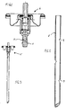
- the valve body without the push button, is shown in more detail in FIG. 1.
- the valve body is preferably a standardized and commercially available dispenser.
- the standard model of the riser tube 8 is outlined in FIG. 2.
- Three notches 9 are made at certain intervals along the outer wall of the tube 8. These holes serve to facilitate the flow of the product through the tube during filling and dispensing.
- the immersion tube is open at the top and bottom.
- the upper end of the round immersion tube 8 is placed over the lower end 10 of the valve body 6.
- the frictional forces hold the tube firmly against the valve body.
- the composition of the dispenser with the immersion tube is outlined in FIG. 3.
- An annular, outwardly projecting shoulder 11 is attached to the lower end of the valve body 6. When the upper part of the immersion tube is put over the lower end 10 of the valve body 6, the shoulder or the annular cone is stretched and stretched the tube at this point, so that it can only be pulled over the cone with great force.
- the immersion tube secured by the attachment 10 of the valve body 6 is firmly connected to the collapsible bag 4. More specifically, the inner compressible bag 4 consists of two opposing layers 12 and 13 of pliable material which have been welded together along their peripheries 14. The bag is then welded to the outer wall of the immersion tube so that the tube is completely inside the bag. The weld seams are made at the point where the immersion tube is placed over the ring-shaped attachment of the valve body.
- the flexible material of the collapsible bag consists of a laminate that consists of layers from the outside in, e.g. can be constructed from polyester, aluminum foils, nylon and low density polyethylene. The individual layers in the laminate are adhesively bonded to one another, and the laminate has a thickness of approximately 134 ⁇ m.
- the standard immersion tube 8 is e.g. made of polyethylene. This ensures that it can be sealed with the low density polyethylene bag.
- the assembly unit 15, consisting of the collapsible bag 4, the immersion tube 8 and the valve body 6 according to FIGS. 4 to 6, is produced according to the invention by means of two vertically opposite welding blocks 16 and 17 (FIG. 8).
- the welding blocks 16 and 17 can be displaced relative to one another in the direction of arrow A, so that the two sides of the blocks can press the layers of fexible material 12 and 13 to be melted against one another or can be connected to the immersion tube 8 in a sandwich-like manner. Under pressure and with the application of heat, above the melting point of polyethylene, the two opposite layers are welded to each other as well as to the part of the outer wall of the immersion tube which has been put over the annular cone of the valve body.
- a semicircular recess 18 is made in each of the two welding blocks so that the assembly unit 15 - consisting of the bag, the tube and the annular support of the valve body - fits exactly.
- Each of the two semicircular depressions 18 has a further semicircular depression 19 in the axial extent, into which the annularly projecting shoulder 11 of the valve stub and the immersion tube 8 lying above it and the layers 12 and 13 fit exactly.
- there is no welding ie the area in the immediate vicinity of the shoulder or the annular cone remains cold. The cone 11 is thus not damaged during the welding process and the part of the immersion tube which is located directly above the cone does not melt. Therefore, the tube does not lose its elasticity at the point mentioned.
- the semicircular depression 20 in each of the welding blocks 16 and 17 is intended so that the materials of the two flexible layers 12 and 13 can be exactly matched to one another by movement during the welding process.
- the flexible material of the two opposite layers 12 and 13 is welded to the outer wall of the immersion tube, with two weld seams above and below the annular shoulder 11. The location in the immediate vicinity of the annular cone 11 remains free.
- the finished assembly unit 15 is inserted into the opening at the upper end of the outer jacket 5.
- the container casing is made of metal in the illustration described, but other materials such as plastic or glass can also be used, provided that the casing maintains its necessary strength against the compressed gas in the outer chamber.
- the propellant gas must be filled into the outer chamber 3 under pressure.
- the edge of the valve body 6 is then clinched to the outer jacket 5 of the can.
- the opening at the upper end of the container 5 and thus the chamber 3 is hermetically sealed.
- a liquid product which is stored in the bag 4 and is to be dispensed in a metered manner is pressed into the collapsible bag 4 by the valve body 6.
- the barrier bag container according to the invention is not only limited to a double-chamber system, but can also be used in multi-chamber systems with barrier bag containers with more than two chambers.
- the flexible material of the collapsible bag is not only limited to the specific laminate described, but also other laminates, e.g. Containing propylene can be used. Immersion tubes made of propylene can easily be used for the welding process. Non-laminated material is also suitable for the production of the collapsible bag. The same applies to the valve body.
- other forms can also be used, such as a pump spray dispenser together with a barrier bag container according to the present invention. In such a case, it is unnecessary to fill a propellant gas into the chamber 3 of the container.
Abstract
Description
Die vorliegende Erfindung betrifft Sperrbeutel-Behälter zum Aufbewahren und Abgeben eines Füllgutes und eine Methode für die Herstellung derselben.The present invention relates to barrier bag containers for storing and dispensing a filling material and to a method for producing the same.
Sperrbeutel-Behälter mit einem Doppelkammer-System sind allgemein bekannt, aber noch nicht weit verbreitet.Barrier bag containers with a double chamber system are generally known, but are not yet widespread.
Diese Art von Behälter enthält einen inneren, zusammendrückbaren Behälter bzw. kollabierbaren Beutel, der von einem äusseren, festen Behälter bzw. Mantel umgeben ist. Dadurch entstehen zwei voneinander unabhängige Kammern; eine innerhalb des zusammendrückbaren, inneren Beutels und die andere zwischen dem äusseren Mantel und dem inneren Beutel. Ein Verschluss in Form eines Ventils oder Dispensers ist über den äusseren Mantel so aufgesetzt, dass der äussere Rand des Verschlusses den oberen Teil des äusseren Mantels einfasst und hermetisch verschliesst. Das Ventil ist in Verbindung mit dem inneren, zusammendrückbaren Beutel, damit nur der Inhalt desselben an die Umwelt abgegeben werden kann. Das Treibgas kommt dadurch mit dem Inhalt des inneren, kollabierbaren Beutels nicht in Kontakt, da dieses in der vom äusseren Mantel und dem inneren Beutel abgetrennten Kammer eingeschlossen ist.This type of container contains an inner, compressible container or collapsible bag, which is surrounded by an outer, solid container or jacket. This creates two independent chambers; one inside the compressible inner bag and the other between the outer jacket and the inner bag. A closure in the form of a valve or dispenser is placed over the outer casing in such a way that the outer edge of the closure surrounds the upper part of the outer casing and hermetically seals it. The valve is connected to the inner, compressible bag so that only the contents of the same can be released to the environment. The propellant gas therefore does not come into contact with the contents of the inner, collapsible bag, since this is enclosed in the chamber separated from the outer jacket and the inner bag.
Eine Belastung für die Umwelt, die dadurch entstehen kann, dass Treibmittel zusammen mit dem Produkt den Beutel verlässt, wird dadurch verhindert, dass bei den Sperrbeutel-Dosen das Treibmittel im Behälter bleibt. Die bekannten Sperrbeutel-Behälter sind relativ kompliziert aufgebaut und die Herstellung kostspielig, weil dazu spezielle Behälter-Komponenten und Apparate benötigt werden.A burden on the environment, which can result from the fact that propellant leaves the bag together with the product, is prevented by the fact that the propellant remains in the container in the sealing bag cans. The known barrier bag containers have a relatively complicated structure and are expensive to produce because special container components and apparatus are required for this.
Der innere, zusammendrückbare Beutel in den bekannten Doppelkammerbehältern wird aus einem soliden aber doch sehr geschmeidigen Material hergestellt. Dazu eignen sich weiche Aluminiumfolien, schmiegsames Plastikmaterial oder laminierte Folien, z.B. Polyolefine, Aluminiumfolien, Nylon und Polyester, die miteinander so verbunden werden, dass sich eine beschichtete bzw. laminierte Folie bildet. Das Material des inneren, zusammendrückbaren Beutels muss von guter Qualität sein, damit keine Diffusion und damit Vermischung von Produkt und Treibmittel auftreten kann.The inner, compressible bag in the well-known double chamber containers is made of a solid but very supple material. Soft aluminum foils, pliable plastic material or laminated foils such as polyolefins, aluminum foils, nylon and are suitable for this Polyester, which are connected to each other so that a coated or laminated film is formed. The material of the inner, compressible bag must be of good quality so that no diffusion and thus mixing of product and blowing agent can occur.
Ein Problem bei der Herstellung von Sperrbeutel-Behältern besteht in der hermetischen Fixierung des inneren, zusammendrückbaren Beutels am Material des Ventilkörpers. Dabei darf es zu keinem Austritt von Produkt und Treibmittel aus den beiden getrennten Kammern kommen. Die Lösung dieses Problems wird durch die Anforderungen an den inneren, kollabierbaren Beutel erschwert. Der innere zusammendrückbare Beutel darf sich nämlich durch den bei der Füllung entstehenden Druck und bei den Falltests während der Qualitätskontrolle nicht loslösen.One problem with the manufacture of barrier bag containers is the hermetic fixation of the inner, compressible bag to the material of the valve body. There must be no leakage of product and propellant from the two separate chambers. The solution to this problem is made difficult by the requirements for the inner, collapsible bag. The inner compressible bag must not become detached due to the pressure created during filling and during the drop tests during quality control.
In einer bekannten Dose dieser Art besteht der innere, zusammendrückbare Beutel aus einem mehrschichtigen Laminat, welches direkt mit dem Ventilkörper verschweisst ist und welcher spezielle Ventilkörper aus Polyethylen besteht. Dieses Material erlaubt, dass der kollabierbare Beutel mit dem Ventilkörper verschweisst werden kann. Die meisten standardisierten und handelsüblichen Ventilkörper für die Behälter haben aber einen Ventilkörper aus Nylon, während der innere, zusammendrückbare Beutel aus Polyolefinen besteht oder Polyolefine enthält. Damit der kollabierbare Beutel aber trotzdem direkt mit dem Ventilkörper verschweisst werden kann, ist ein spezieller Ventilkörper erforderlich, der aus einem anderen Material besteht als aus konventionellem Nylon; z.B. aus Polyolefinen, wie oben bereits erwähnt. In dieser Form kann der innere, zusammendrückbare Beutel problemlos mit dem Ventilkörper verschweisst werden.In a known can of this type, the inner, compressible bag consists of a multilayer laminate which is welded directly to the valve body and which special valve body is made of polyethylene. This material allows the collapsible bag to be welded to the valve body. However, most standardized and commercially available valve bodies for the containers have a valve body made of nylon, while the inner, compressible bag is made of polyolefins or contains polyolefins. So that the collapsible bag can still be welded directly to the valve body, a special valve body is required which is made of a different material than conventional nylon; eg from polyolefins, as already mentioned above. In this form, the inner, compressible bag can be easily welded to the valve body.
Der Nachteil bei Verwendung von Polyolefinen als Ventilmaterial besteht darin, dass die Beständigkeit von Polyolefinen gegenüber Gasen, im Vergleich zum konventionellen Nylon, geringer ist. Dieser Nachteil wird dadurch kompensiert, dass bei den oben beschriebenen Sperrbeutel-Behältern Epoxid-Harz zur Anwendung kommt, mit dem man das Ventil, nach der Verschweissung mit dem zusammendrückbaren Beutel, bedeckt und abdichtet. Dieser zusätzliche Arbeitsgang verkompliziert den Herstellungsprozess und erhöht die Kosten für den Behälter. Es wird daher vorgeschlagen, dass der innere, zusammendrückbare Beutel innerhalb des Behälters durch die Verwendung eines speziellen Verbindungsstückes (Eintauchröhrchen) am Ventil befestigt wird und zwar so, dass das Eintauchröhrchen einerseits mit dem kollabierbaren Beutel und andererseits mit einer speziell entworfenen Ventilkonfiguration z.B. gemäss U.S.Patent Nr. 3.342.377 und Nr. 4.969.577 verbunden ist.The disadvantage of using polyolefins as valve material is that the resistance of polyolefins to gases is lower than that of conventional nylon. This disadvantage is compensated for by the fact that epoxy resin is used in the barrier bag containers described above, with which the valve is covered and sealed after being welded to the compressible bag. This additional operation complicates the manufacturing process and increases the cost of the container. It is therefore proposed that the inner, compressible bag within the container is attached to the valve by using a special connector (immersion tube) in such a way that the immersion tube on the one hand with the collapsible bag and on the other hand with a specially designed valve configuration e.g. according to U.S. Patent No. 3,342,377 and No. 4,969,577.
Die an eine spezielle Ventilkonfiguration, an das Eintauchröhrchen sowie an spezielles Ventilmaterial geknüpften Bedingungen bei diesen bekannten Sperrbeutel-Behältern sind unvorteilhaft, weil sie die Gestaltungsfreiheit reduzieren und den Gebrauch von standardisierten, handelsüblichen Behälterkomponenten (Ventil) nicht mehr gestatten. Es besteht deshalb das Bedürfnis nach verbesserten, kostengünstigen Sperrbeutel-Behältern sowie nach Herstellungsverfahren derselben, die eine grosse Gestaltungsfreiheit für verschiedene Anwendungsmöglichkeiten erlaubt. Weiterhin ist eine vereinfachte Herstellung erwünscht und soll der Vorteil der niedrigeren Kosten bei Verwendung von Ventilen und Verbindungsstücken ab Stange wahrgenommen werden können.The conditions associated with a special valve configuration, the immersion tube and special valve material in these known barrier bag containers are disadvantageous because they reduce the design freedom and no longer permit the use of standardized, commercially available container components (valve). There is therefore a need for improved, inexpensive barrier bag containers and for manufacturing processes therefor, which allow great freedom of design for various possible uses. Simplified production is also desired and the advantage of lower costs when using valves and connecting pieces from the rod should be perceived.
Die vorliegende Erfindung besteht in der Schaffung eines verbesserten Sperrbeutel-Behälters, welcher die oben beschriebenen Probleme der konventionellen Sperrbeutel-Behälter kompensiert bzw. überwindet. Ein spezielles Charakteristikum der vorliegenden Erfindung besteht in der Zusammensetzung und dem Verfahren zur Herstellung eines neuartigen Sperrbeutel-Behälters, welcher eine grössere Gestaltungsfreiheit für die verschiedenen Anwendungsmöglichkeiten gestattet. Ein weiteres Charakteristikum der Erfindung liegt in der Vereinfachung bei der Herstellung sowie beim Gebrauch von günstigen, standardisierten, handelsüblichen Verntilen mit Eintauchröhrchen. Man braucht also keine speziellen Ventilkonfigurationen oder Materialien, wie sie früher für die Herstellung von Sperrbeutel-Behältern verwendet worden sind.The present invention is to provide an improved barrier bag container which overcomes the problems of the conventional barrier bag container described above compensates or overcomes. A special characteristic of the present invention consists in the composition and the method for producing a novel barrier bag container, which allows greater freedom of design for the various possible uses. Another characteristic of the invention lies in the simplification in the manufacture and in the use of cheap, standardized, commercially available valves with immersion tubes. There is no need for any special valve configurations or materials, as they were previously used for the production of barrier bag containers.
Diese und noch andere vorteilhafte Eigenschaften werden durch den der Erfindung zugrunde liegenden Sperrbeutel-Behälter für das Aufbewahren und das Abgeben eines Füllgutes erreicht. Der Behälter enthält einen äusseren Mantel und ein Ventil, welches am äusseren Mantel des Behälters befestigt ist. Das Ventil des Dispensers enthält einen manuell betätigbaren Ventilknopf, welcher bei Betätigung das Produkt im Beutel freisetzen kann. Ein innerer, zusammendrückbarer Beutel ist innerhalb des Sperrbeutel-Behälters eingebracht, welcher das freizusetzende Produkt enthält. Ein Eintauchröhrchen ist über einen sich am Ventilkörper befindenden ringförmigen Konus gestülpt und dadurch gesichert. Das Eintauchröhrchen befindet sich innerhalb des kollabierbaren Beutels, damit das Produkt im Beutel via Eintauchröhrchen und Ventil freigesetzt werden kann. Der innere, zusammendrückbare Beutel ist am oberen Teil des Eintauchröhrchens befestigt, welches seinerseits über einen ringförmigen, konusähnlichen Vorsprung gestülpt ist, der sich am Ventilkörper befindet.These and still other advantageous properties are achieved by the barrier bag container on which the invention is based, for storing and dispensing a filling material. The container contains an outer jacket and a valve which is attached to the outer jacket of the container. The valve of the dispenser contains a manually operable valve button, which can release the product in the bag when actuated. An inner, compressible bag is placed within the barrier bag container which contains the product to be released. An immersion tube is placed over an annular cone on the valve body and is thereby secured. The immersion tube is located inside the collapsible pouch so that the product can be released in the pouch via the immersion tube and valve. The inner, compressible bag is attached to the upper part of the immersion tube, which in turn is placed over an annular, cone-like projection, which is located on the valve body.
Überraschenderweise hat man herausgefunden, dass es einfacher und weniger problematisch ist, den kollabierbaren Beutel direkt am äusseren oberen Rand des relativ dünnen Eintauchröhrchens zu befestigen, anstatt an einem speziell konstruierten Verbindungsstück oder direkt am Ventil. Die Befestigung erfolgt bevorzugt durch Schweissen. Bei der Anbringung der Schweissnähte an der Stelle, wo das Eintauchröhrchen über den ringförmigen Vorsprung des Ventilkörpers gestülpt wird, werden keine speziellen Schweissspindel oder Schweisskerne benötigt um das Innere des Eintauchröhrchens während des Schweissens zu unterstützen, da diese Funktion durch den stabilen, ringförmigen Konus des Ventils gewährleistet wird, über welchen das Eintauchröhrchen gestülpt ist. Mit der erfindungsgemässen Vorrichtung und dem Verfahren wird weniger Ausschuss produziert und eine höhere Produktion ermöglicht. Im weiteren können beim Verschweissen des Beutels mit einem standardisierten Eintauchröhrchen kommerzielle Ventile verwendet werden, die einen höheren Grad an Flexibilität zeigen und auch anwenderfreundlicher sind. Ebenso werden die Kosten beim Gebrauch von Ventilen ab der Stange reduziert und komplizierte Verbindungsstücke, spezielle Ventilkonfigurationen sowie Materialien, wie sie früher für die Herstellung von Sperrbeutel-Behältern verwendet worden sind, werden nicht mehr benötigt.Surprisingly, it has been found that the collapsible is easier and less problematic Attach the bag directly to the outer top of the relatively thin dip tube, rather than to a specially designed connector or directly to the valve. The attachment is preferably carried out by welding. When attaching the weld seams at the point where the immersion tube is placed over the annular projection of the valve body, no special welding spindle or welding cores are required to support the interior of the immersion tube during welding, since this function is achieved by the stable, annular cone of the valve is guaranteed, over which the immersion tube is put. With the device and the method according to the invention, fewer rejects are produced and higher production is made possible. In addition, when the bag is sealed with a standardized immersion tube, commercial valves can be used which show a higher degree of flexibility and are also more user-friendly. It also reduces the cost of off-the-shelf valve use and eliminates the need for complex connectors, special valve configurations, and materials that were previously used in the manufacture of barrier bag containers.
Ein weiteres erfindungsgemässes Merkmal, des Sperrbeutel-Behälters besteht darin, dass vor dem Schweissen das Eintauchröhrchen fest mit dem Ventil verbunden werden muss, d.h. das eine Ende des Eintauchröhrchens wird über den ringförmigen Konus des Ventils gestülpt. Das flexible Material des zusammendrückbaren Beutels wird anschliessend an den Teil des Eintauchröhrchens angeschweisst, der über diesen ringrömigen Vorsprung des Ventilkörpers gestülpt worden ist. Dazu werden zwei sich vertikal gegenüberliegende Schweissblöcke verwendet, welche den Beutel, das Eintauchröhrchen und den Ventilkonus genau einspannen können.Another feature of the barrier bag container according to the invention is that the immersion tube must be firmly connected to the valve before welding, ie one end of the immersion tube is put over the annular cone of the valve. The flexible material of the compressible bag is then welded to the part of the immersion tube which has been put over this annular projection of the valve body. For this purpose, two vertically opposite welding blocks are used, which can clamp the bag, the immersion tube and the valve cone exactly.
Die Ventilunterseite mit dem bereits besprochenen ringfömigen Vorsprung dient letztlich dazu, das eine Ende des Eintauchröhrchens entgegen dem Druck der Schweissblöcke zu unterstützen und ein problemloses und genaues Verschweissen mit dem geschmeidigen Material des Beutels zu erreichen.The underside of the valve with the annular projection already discussed ultimately serves to support the one end of the immersion tube against the pressure of the welding blocks and to achieve problem-free and accurate welding with the supple material of the bag.
Der Teil des Ventils, über den das Eintauchröhrchen gestülpt wird, hat eine ringförmig vorstossende Schulter, die eine Art Konus bildet. Das Überstülpen des Eintauchröhrchens über den Konus garantiert einen festen Sitz, so dass auch bei der Befüllung des kollabierbaren Behälters unter Druck, kein Loslösen von Ventil und Röhrchen erfolgt. Beim Schweissen wird die Stelle, wo das Eintauchröhrchen mit dem kollabierbaren Behälter oberhalb des konischen Teil liegt freigehalten, d.h. es wird keine Schweissnaht angelegt, da der Konus durch die Hitze beschädigt werden und das darauf liegende Röhrchen schmelzen könnte, was zu einem Verlust der Dehnungsfähigkeit führen würde. Es bestünde sonst die Gefahr, dass sich das Eintauchröhrchen mit dem angeschweissten Beutel beim Auffüllen des Behälters oder bei Falltests in der Qualitätskontrolle, vom Ventil loslösen könnte. Daher ist es erfindungsgemäss notwendig, dass der innere, zusammendrückbare Beutel nur ober- und unterhalb des ringförmigen Konus und axial zu demselben mit dem Eintauchröhrchen verschweisst wird. Unmittelbar über dem ringförmigen Konus wird also keine Schweissnaht angebracht.The part of the valve over which the immersion tube is placed has an annular shoulder that forms a kind of cone. Slipping the immersion tube over the cone guarantees a tight fit, so that even when the collapsible container is filled under pressure, the valve and tube are not released. When welding, the place where the immersion tube with the collapsible container lies above the conical part is kept free, i.e. no weld seam is created because the cone could be damaged by the heat and the tube on it could melt, which would lead to a loss of elasticity. Otherwise there would be a risk that the immersion tube with the welded-on bag could become detached from the valve when filling the container or during drop tests in quality control. It is therefore necessary according to the invention that the inner, compressible bag is only welded to the immersion tube above and below the annular cone and axially to the same. No weld seam is therefore made directly above the annular cone.
Das Ventil und das Eintauchröhrchen in der beschriebenen Anordnung sind standardisiert und alle Komponenten im Handel erhältlich. Der Gebrauch von speziellen Verbindungsstücken und Ventilkonfigurationen für die Befestigung des kollabierbaren Beutels mit dem Sperrbeutel-Behälter kann, wie bereits gesagt, vermieden werden, und die Verwendung von speziellem Material für die Konstuktion der Ventile ist ebenfalls überflüssig. Die standardisierten und im Handel erhältlichen Eintauchröhrchen sind aus Polyethylen oder Polypropylen gefertigt und der innere, zusammendrückbare Beutel besteht i.a. aus Polyethylen, Polypropylen oder aus einem Laminat aus Polyethylen und Polypropylen. Daher können Standardventile aus Nylon ohne Inkompatibilitätsrisiko verwendet werden, weil die Verbindung zwischen dem Ventil und dem Eintauchröhrchen nicht geschweisst wird. Die feste Verbindung zwischen dem Eintauchröhrchen und dem Ventilkörper beruht nur auf Reibungskräften, eine Verschweissung der beiden Teile ist somit nicht nötig.The valve and the immersion tube in the arrangement described are standardized and all components are commercially available. The use of special connectors and valve configurations for attaching the collapsible bag to the barrier bag container can be avoided, as already said, and the use of special material for the construction of the valves is also unnecessary. The standardized and in the trade Available immersion tubes are made of polyethylene or polypropylene and the inner, compressible bag generally consists of polyethylene, polypropylene or a laminate of polyethylene and polypropylene. Standard nylon valves can therefore be used without the risk of incompatibility because the connection between the valve and the immersion tube is not welded. The fixed connection between the immersion tube and the valve body is based only on frictional forces, so welding of the two parts is not necessary.
In dem erfindungsgemässen Behälter befindet sich zwischen dem äusseren Mantel und dem inneren, zusammendrückbaren Beutel ein komprimiertes Gas, das auf das Produkt im kollabierbaren Beutel wirkt. Durch diesen Druck wird das Produkt nach der Betätigung des Ventilknopfs aus dem Beutel ausgetrieben. Bevorzugt findet ein solches Ventil Verwendung, welches nach der Fertigstellung des Behälters das kontinuerliche und sehr schnelle Einfüllen eines Produktes in den Beutel erlaubt. Das Treibmittel wird während der Produktion unter Druck in den Behälter eingebracht. Das erfindungsgemässe Verfahren zur Herstellung eines Sperrbeutel-Behälters zum Aufbewahren und Abgeben eines Produktes ist in den Ansprüchen definiert und schliesst insbesondere folgende Elemente ein: einen Ventilkörper; ein Eintauchröhrchen, dessen eines Ende über einen ringförmigen Konus an der Unterseite des Ventilkörpers gestülpt wird; ein zusammendrückbarer Beutel, der an der Aussenwand des Eintauchröhrchens unmittelbar ober- und unterhalb des ringförmigen Konus angeschweisst ist sowie die Montage dieser Einheit - bestehend aus dem beutel, dem Eintauchröhrchen und dem Ventilkörper - am äusseren Mantel des Behälters.In the container according to the invention there is a compressed gas between the outer jacket and the inner, compressible bag, which acts on the product in the collapsible bag. This pressure expels the product from the bag after the valve button has been actuated. Such a valve is preferably used, which allows the continuous and very quick filling of a product into the bag after the completion of the container. The blowing agent is introduced into the container under pressure during production. The method according to the invention for producing a barrier bag container for storing and dispensing a product is defined in the claims and includes in particular the following elements: a valve body; an immersion tube, one end of which is slipped over an annular cone on the underside of the valve body; a compressible bag that is welded to the outer wall of the immersion tube immediately above and below the ring-shaped cone and the assembly of this unit - consisting of the bag, the immersion tube and the valve body - on the outer jacket of the container.
Die Einheit, bestehend aus Ventilkörper, Eintauchröhrchen und dem kollabierbaren Beutel kann gemäss der Erfindung verwendungsabhängig hergestellt und als separate Montageeinheit an die Konvektionierung bzw. an die Abfüllerei geliefert werden. Bei der Befüllung wird die Montageeinheit mit dem äusseren Mantel zusammengesetzt, wobei sich das Eintauchröhrchen mit dem Beutel im Innern des äusseren Mantels befindet.The unit, consisting of the valve body, immersion tube and the collapsible bag, can be manufactured according to the invention depending on the application and can be delivered to the convection or to the bottling plant as a separate assembly unit. When filling, the assembly unit is put together with the outer jacket, the immersion tube with the bag being located inside the outer jacket.
Während des Zusammensetzens der Montageeinheit mit dem äusseren Mantel des Behälters wird gleichzeitig unter Druck komprimiertes Gas in die Kammer zwischen dem äusseren Mantel und dem kollabierbaren Beutel eingefüllt. Anschliessend wird durch das Ventil das Füllgut ebenfalls mit Druck in den zusammendrückbaren Beutel gepresst.During assembly of the assembly unit with the outer jacket of the container, compressed gas is simultaneously filled into the chamber between the outer jacket and the collapsible bag. Then the valve also presses the contents into the compressible bag.
Diese und andere Eigenschaften, Merkmale und Vorteile der oben beschriebenen Erfindung werden anhand der folgenden Abbildungen noch näher erläutert. Die Figuren dienen nur der Illustration und zeigen eine Ausführungsform in Übereinstimmung mit der vorliegenden Erfindung.
Figur 1 zeigt einen vergrösserten Querschnitt eines standardisierten und im Handel erhältlichen Druckventils;- Figur 2 zeigt die Vorderansicht eines standardisierten Eintauchröhrchens in dessen Wand kleine Öffnungen angebracht sind, die den Fluss des Produktes durch das Röhrchen während der Füllung und Abgabe erleichtern;
- Figur 3 zeigt einen Querschnitt nach der Montage des Ventils aus Fig. 1 und dem Eintauchröhrchen aus Fig. 2 in Originalgrösse;
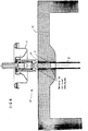
Figur 4 zeigt eine Vorderansicht, z.T. als Querschnitt mit einem über den unteren Teil des Ventilkörpers gestülpten Eintauchröhrchen, mit verschweisstem kollabierbaren Beutel;- Figur 5 ist eine Aufsicht der Baugruppe aus Fig. 4;
Figur 6 ist eine vergrösserte Darstellung des oberen Teils aus Fig. 4, wobei das flexible Material des kollabierbaren Beutels mit der Aussenwand des Eintauchröhrchens verschweisst ist und dieses über den ringförmigen Konus am Ventilkörper, gestülpt ist und wobei im Bereich des Konus keine Schweissnaht angebracht ist;- Figur 7 zeigt einen Querschnitt durch einen vollständigen Sperrbeutel-Behälter;
Figur 8 zeigt eine schematische Darstellung mit den beiden Schweissblöcken und der erfindungsgemässen Montageeinheit;Figur 9 ist eine Vorderansicht der Arbeitseinheit des unteren Schweissblocks entlang der Linie IX - IX, gemäss Fig. 8;Figur 10 ist die rechte Seitenansicht des Schweissblocks, gemäss Fig. 9;- Figur 11 ist eine vergrösserte Ansicht des Schweissblocks aus Fig. 9 mit den Vertiefungen für denjenigen Teil der Montageeinheit, die verschweisst werden muss;
- Figur 12 zeigt eine vergrösserte Aufsicht auf den Schweissblock, gemäss Fig. 11.
- Figure 1 shows an enlarged cross section of a standardized and commercially available pressure valve;
- Figure 2 shows the front view of a standardized immersion tube in the wall of which there are small openings which facilitate the flow of the product through the tube during filling and dispensing;
- FIG. 3 shows a cross section after assembly of the valve from FIG. 1 and the immersion tube from FIG. 2 in the original size;
- FIG. 4 shows a front view, partly as a cross section with an immersion tube placed over the lower part of the valve body, with a welded collapsible bag;
- Figure 5 is a top view of the assembly of Figure 4;
- Figure 6 is an enlarged view of the upper part of Figure 4, wherein the flexible material of the collapsible bag is welded to the outer wall of the immersion tube and this is put over the annular cone on the valve body, and wherein no weld seam is attached in the region of the cone;
- FIG. 7 shows a cross section through a complete barrier bag container;
- FIG. 8 shows a schematic illustration with the two welding blocks and the assembly unit according to the invention;
- FIG. 9 is a front view of the working unit of the lower welding block along the line IX-IX, according to FIG. 8;
- Figure 10 is the right side view of the welding block, according to Fig. 9;
- FIG. 11 is an enlarged view of the welding block from FIG. 9 with the depressions for that part of the assembly unit which has to be welded;
- FIG. 12 shows an enlarged top view of the welding block, according to FIG. 11.
Ein Doppelkammer-Sperrbeutel-Behälter 1, wie er mit vorliegender Erfindung offenbart wird, ist in Figur 7 dargestellt. Der Behälter 1 weist zwei Kammern auf. Die Kammer 2 enthält ein visköses Produkt und die Kammer 3 ein komprimiertes Treibgas. Die Kammer 2 befindet sich innerhalb des Beutels 4, welcher sich innerhalb des Behälters 5 der Dose 1 befindet. Die zweite Kammer 3, die für das Treibgas reserviert ist, wird durch den Raum zwischen dem äusseren Mantel und dem inneren kollabierbaren Beutel 4 gebildet.A double-chamber
Ein Ventilkörper 6 ist auf dem äusseren Mantel des Behälters 5 befestigt und verschliesst dessen obere Öffnung. Die Verbindung des Ventilkörpers ist mit dem Behälter 5 erfolgt indem der äussere Rand des Ventilkörpers am oberen, offenen Flanschhals des äusseren Behälters befestigt wird, z.B. durch Verclinchen. Der Ventilkörper enthält einen manuell bedienbaren Ventilknopf 7, der bei Betätigung das Produkt im zusammendrückbaren Beutel freisetzt.A
Der Ventilkörper, ohne den Druckknopf, ist in Fig. 1 detaillierter dargestellt. Der Ventilkörper ist bevorzugt ein standardisierter und im Handel erhältlicher Dispenser. Das Standardmodell des Steigröhrchens 8 ist in der Fig. 2 skizziert. Drei Kerben 9 sind in gewissen Abständen entlang der Aussenwand des Röhrchens 8 angebracht. Diese Löcher dienen dazu, den Fluss des Produktes durch das Röhrchen während der Füllung und Abgabe zu erleichtern. Das Eintauchröhrchen ist, wie Fig. 2 zeigt, oben und unten offen. Das obere Ende des runden Eintauchröhrchens 8 wird über das untere Ende 10 des Ventilköpers 6 gestülpt. Dabei halten die Reibungskräfte das Röhrchen fest am Ventilkörper. Die Zusammensetzung des Dispensers mit dem Eintauchröhrchen ist in Fig. 3 skizziert. Eine ringförmige, nach aussen vorspringede Schulter 11 ist am unteren Ende des Ventilkörpers 6 angebracht. Wenn der obere Teil des Eintauchröhrchens über das untere Ende 10 des Ventilkörpers 6 gestülpt wird, spannt und dehnt die Schulter bzw. der ringförmige Konus das Röhrchen an dieser Stelle, sodass es nur noch unter grosser Kraftanwendung über den Konus gezogen werden kann.The valve body, without the push button, is shown in more detail in FIG. 1. The valve body is preferably a standardized and commercially available dispenser. The standard model of the
Das durch den Vorsatz 10 des Ventilkörpers 6 gesicherte Eintauchröhrchen wird fest mit dem kollabierbaren Beutel 4 verbunden. Genauer gesagt, der innere, zusammendrückbare Beutel 4 besteht aus zwei gegenüberliegenden Schichten 12 und 13 aus geschmeidigem Material, welche entlang ihrer Peripherien 14 zusammengeschweisst wurden. Der Beutel wird dann an die Aussenwand des Eintauchröhrchens so angeschweisst, dass sich das Röhrchen vollständig im Innern des Beutels befindet. Die Schweissnähte werden an der Stelle angebracht, wo das Eintauchröhrchen über den ringförmigen Vorsatz des Ventilkörpers gestülpt ist. Das flexible Material des kollabierbaren Beutels besteht aus einem Laminat, das von aussen nach innen aus Schichten z.B. aus Polyester, Aluminiumfolien, Nylon und Polyethylen niederer Dichte aufgebaut sein kann. Die einzelnen Schichten im Laminat sind adhäsiv miteinander verbunden, und das Laminat hat eine Dicke von ungefähr 134 µm. Das Standardeintauchröhrchen 8 ist z.B. aus Polyethylen hergestellt. Dadurch wird gewährleistet, dass es mit dem Polyethylen niederer Dichte des Beutels verschweisst werden kann.The immersion tube secured by the
Die Montageeinheit 15, bestehend aus dem kollabierbaren Beutel 4, dem Eintauchröhrchen 8 und dem Ventilkörper 6 gemäss den Figuren 4 bis 6 wird erfindungsgemäss mittels zwei sich vertikal gegenüberliegenden Schweissblöcken 16 und 17 (Fig. 8) hergestellt. Die Schweissblöcke 16 und 17 sind gegeneinander in Pfeilrichtung A verschiebbar, sodass die beiden Seiten der Blöcke die zu verschmelzenden Schichten des fexiblen Materials 12 und 13 gegeneinander pressen können bzw. diese mit dem Eintauchröhrchen 8 sandwichartig verbunden werden können. Unter Druck und unter der Anwendung von Hitze, über dem Schmelzpunkt von Polyethylen, werden die beiden sich gegenüberliegenden Schichten sowohl miteinander als auch mit dem Teil der Aussenwand des Eintauchröhrchens verschweisst, der über den ringförmigen Konus des Ventilkörpers gestülpt worden ist.The
Eine halbrunde Vertiefung 18 wird in jedem der beiden Schweissblöcke angebracht, damit die Montageeinheit 15 - bestehend aus dem Beutel, dem Röhrchen und dem ringförmigen Stützen des Ventilkörpers - genau hineinpasst. Jede der beiden halbrunden Vertiefungen 18 haben in der axialen Ausdehnung eine weitere halbrunde Vertiefung 19, in die die ringförmig vorstossende Schulter 11 des Ventilstutzens und das darüberliegende Eintauchröhrchen 8 sowie die Schichten 12 und 13 genau hineinpassen. An dieser Stelle wird jedoch nicht verschweisst d.h. der Bereich in unmittelbarer Nähe der Schulter bzw. des ringförmigen Konus bleibt kalt. Der Konus 11 wird somit während des Schweissvorganges nicht beschädigt und der Teil des Eintauchröhrchens der sich unmittelbar über dem Konus befindet schmilzt nicht. Daher verliert das Röhrchen an der genannten Stelle seine Dehnbarkeit nicht. Bei der Füllung des Behälters oder bei Falltests während der Qualitätskontrolle verhindern die Reibungskräfte zwischen dem ringförmigen Konus und dem Eintauchröhrchen ein Ablösen des Röhrchens mit dem kollabierbaren Beutel von dem Ventilkörper. Die halbkreisförmige Vertiefung 20 in jedem der Schweissblöcke 16 und 17 ist dazu bestimmt, die Materialien der beiden flexiblen Schichten 12 und 13 während des Schweissvorganges durch Bewegung genau aneinander angeglichen werden können. Das flexible Material der beiden gegenüberliegenden Schichten 12 und 13 wird an die Aussenwand des Eintauchröhrchens angeschweisst und zwar mit zwei Schweissnähten ober- und unterhalb der ringförmigen Schulter 11. Die Stelle in unmittelbarer Nähe des ringförmigen Konus 11 bleibt dabei frei.A
Nach dem Schweissvorgang wird die fertige Montageeinheit 15 in die Öffnung am oberen Ende des äusseren Mantels 5 eingesetzt. Der Behältermantel ist in der beschriebenen Darstellung aus Metall, jedoch können auch andere Materialien wie Plastik oder Glas verwendet werden vorausgesetzt, dass der Mantel seine notwendige Festigkeit gegenüber dem komprimierten Gas in der äusseren Kammer beibehält. Bevor der Rand des Ventilkörpers 6 mit dem äusseren Mantel 5 der Dose verclincht wird, muss unter Druck das Treibgas in die äussere Kammer 3 eingefüllt werden. Der Rand der Ventilkörpers 6 wird anschliessend mit dem äusseren Mantel 5 der Dose verclincht. Dadurch wird die Öffnung am oberen Ende des Behälters 5 und und damit die Kammer 3 hermetisch verschlossen. Ein flüssiges Produkt, das im Beutel 4 aufbewahrt wird und dosierbar abgegeben werden soll, wird durch den Ventilkörper 6 in den kollabierbaren Beutel 4 eingepresst.After the welding process, the
Mit den beschriebenen Merkmalen und Verfahrensschritten wird ausserdem für das Innere des Eintauchröhrchens während des Schweissvorganges keine spezielle Spindel benötigt, da eine entsprechende unterstützende Wirkung vom Ventilkörper vernommen wird. Das geschmeidige Material des inneren, zusammendrückbaren Beutels 4 ist so am Eintauchröhrchen befestigt, dass ein Übertreten von Treibgas und Füllgut jeweils in die andere Kammer des Behälters nicht möglich ist. Desweiteren wird durch die genannte Verbindungsart verhindert, dass sich das Eintauchröhrchen beim Füllvorgang oder bei Falltests während der Qualitätskontrolle mitsamt dem kollabierbaren Beutel vom Ventil ablöst. Darüberhinaus werden keine speziellen Verbindungsstücke oder speziell konfigurierte Ventile benötigt. Durch die Verwendung von standardisierten und im Handel erhältlichen Ventilen mit Eintauchröhrchen, werden die Kosten verringert und die Flexibilität für das Design des Behälters wird erhöht. Der Sperrbeutel-Behälter der Erfindung ist auch relativ einfach herzustellen und man benötigt keine speziellen Epoxid-Harze zum hermetischen Versiegeln des Behälters.With the features and method steps described, no special spindle is additionally required for the interior of the immersion tube during the welding process, since a corresponding supporting effect is heard by the valve body. The supple material of the inner,
Weitere Änderungen und Modifikationen liegen im Bereich des fachmännischen Handels. Zum Beispiel ist der Sperrbeutel-Behälter gemäss Erfindung nicht nur auf ein Doppelkammersystem eingeschränkt, sondern kann auch bei Mehrkammersystemen also bei Sperrbeutel-Behältern mit mehr als zwei Kammern verwendet werden. Desweiteren ist das flexible Material des kollabierbaren Beutels nicht nur auf das beschriebene, spezifische Laminat beschränkt, sondern es können auch andere Laminate, die z.B. Propylen enthalten, verwendet werden. Eintauchröhrchen aus Propylen sind für den Schweissvorgang ohne weiteres verwendbar. Für die Herstellung des kollabierbaren Beutels ist auch nicht laminiertes Material geeignet. Ähnliches gilt für die Ventilkörper. So können auch andere Formen benutzt werden wie bspw. ein Pumpspraydispenser zusammen mit einem Sperrbeutel-Behälter gemäss vorliegender Erfindung. In einem solchen Fall ist es überflüssig ein Treibgas in die Kammer 3 des Behälters einzufüllen.Further changes and modifications are in the area of professional trade. For example, the barrier bag container according to the invention is not only limited to a double-chamber system, but can also be used in multi-chamber systems with barrier bag containers with more than two chambers. Furthermore, the flexible material of the collapsible bag is not only limited to the specific laminate described, but also other laminates, e.g. Containing propylene can be used. Immersion tubes made of propylene can easily be used for the welding process. Non-laminated material is also suitable for the production of the collapsible bag. The same applies to the valve body. Thus, other forms can also be used, such as a pump spray dispenser together with a barrier bag container according to the present invention. In such a case, it is unnecessary to fill a propellant gas into the chamber 3 of the container.
Claims (12)
einen Aussenbehälter;
ein auf diesen Aussenbehälter montiertes Abgabeventil mit einem manuell betätigbaren Ventilknopf, welcher zum Abgeben des Füllgutes aus dem Behälter eingedrückt werden kann;
einen zusammendrückbaren inneren Behälter, innerhalb des Aussenbehälters zum Aufbewahren des Füllgutes;
und ein Eintauchröhrchen, welches mit seinem einen Ende am Ventilkörper befestigt ist und in den zusammendrückbaren Innenbehälter hineinragt um bei betätigtem Abgabeventil Füllgut aus dem Innenbehälter dem Abgabeventil zuzuführen,
welcher Ventilkörper einen unteren Teil mit einer ringförmig vorstossenden Schulter aufweist, über die das Eintauchröhrchen mitsamt dem kollabierbaren Innenbehälter gestülpt ist und so am genannten Ventilkörper festsitzt und dadurch eine feste Verbindung zwischem dem Ventilkörper und dem Eintauchröhrchen mit dem daran befestigten kollabierbaren Innenbehälter entsteht, welcher zusammendrückbare Innenbehälter unmittelbar neben der Stelle am Eintauchröhrchen befestigt ist, wo dieses über die ringförmig vorstossenden Schulter gestülpt ist.Barrier bag container for storing and dispensing a filling, comprising:
an outer container;
a dispensing valve mounted on this outer container with a manually operable valve button which can be pressed in for dispensing the filling material from the container;
a compressible inner container within the outer container for storing the contents;
and an immersion tube which is fastened at one end to the valve body and projects into the compressible inner container in order to supply filling material from the inner container to the dispensing valve when the dispensing valve is actuated,
which valve body has a lower part with a ring-shaped projecting shoulder, over which the immersion tube together with the collapsible inner container is placed and is thus firmly attached to the so-called valve body, thereby creating a firm connection between the valve body and the immersion tube with the collapsible inner container attached to it, which compressible inner container is attached directly next to the point on the immersion tube, where it is placed over the annular shoulder.
ein Abgabeventil mit einem Ventildeckel und einem manuell betätigbaren Ventilknopf, welcher zum Abgeben des Füllgutes aus dem Behälter eingedrückt werden kann;
einen zusammendrückbaren inneren Behälter zum Aufbewahren des Füllgutes;
und ein Eintauchröhrchen, welches mit seinem einen Ende am Ventilkörper befestigt ist und in den zusammendrückbaren Innenbehälter hineinragt um bei betätigtem Abgabeventil Füllgut aus dem Innenbehälter dem Abgabeventil zuzuführen,
welcher Ventilkörper einen unteren Teil mit einer ringförmig vorstossender Schulter aufweist, über die das Eintauchröhrchen mitsamt dem kollabierbaren Innenbehälter gestülpt ist und so am genannten Ventilkörper festsitzt und dadurch eine feste Verbindung zwischen dem Ventilkörper und dem Eintauchröhrchen mit dem daran befestigten kollabierbaren Innenbehälter entsteht, welcher zusammendrückbare Innenbehälter unmittelbar neben der Stelle am Eintauchröhrchen befestigt ist, wo dieses mit beim Ventilkörper verbunden ist.Assembly unit for producing a barrier bag container according to claim 1, comprising:
a dispensing valve with a valve cover and a manually operable valve button, which can be pressed in to dispense the filling material from the container;
a compressible inner container for storing the contents;
and an immersion tube which is fastened at one end to the valve body and projects into the compressible inner container in order to supply filling material from the inner container to the dispensing valve when the dispensing valve is actuated,
which valve body has a lower part with an annularly projecting shoulder, over which the immersion tube together with the collapsible inner container is placed and is thus firmly attached to the so-called valve body, thereby creating a firm connection between the valve body and the immersion tube with the collapsible inner container attached to it, which compressible inner container is attached directly next to the point on the immersion tube where it is connected to the valve body.
Applications Claiming Priority (2)
| Application Number | Priority Date | Filing Date | Title |
|---|---|---|---|
| US93794292A | 1992-09-01 | 1992-09-01 | |
| US937942 | 1992-09-01 |
Publications (2)
| Publication Number | Publication Date |
|---|---|
| EP0585908A2 true EP0585908A2 (en) | 1994-03-09 |
| EP0585908A3 EP0585908A3 (en) | 1995-02-15 |
Family
ID=25470607
Family Applications (1)
| Application Number | Title | Priority Date | Filing Date |
|---|---|---|---|
| EP93114001A Withdrawn EP0585908A3 (en) | 1992-09-01 | 1993-09-01 | Container with insertable bag. |
Country Status (1)
| Country | Link |
|---|---|
| EP (1) | EP0585908A3 (en) |
Cited By (18)
| Publication number | Priority date | Publication date | Assignee | Title |
|---|---|---|---|---|
| DE4427175A1 (en) * | 1994-08-01 | 1996-02-08 | Coster Tecnologie Speciali Spa | Unit |
| US5873491A (en) * | 1997-04-14 | 1999-02-23 | Valois S.A. | Set of components for assembly as a dispensing package of the non-vented type having an internal, collapsible bag |
| WO1999043571A1 (en) * | 1998-02-27 | 1999-09-02 | Boehringer Ingelheim International Gmbh | Container for a medicinal liquid |
| US5950880A (en) * | 1997-04-14 | 1999-09-14 | Valois S.A. | Set of components for assembly as a dispensing package of the non-vented type having a take-up piston |
| WO2002062679A1 (en) * | 2001-02-08 | 2002-08-15 | Stoffel Hans F | Method for producing spray cans comprising an inner container |
| US6685691B1 (en) | 1998-02-27 | 2004-02-03 | Boehringer Ingelheim Gmbh | Container for a medicinal liquid |
| US6988496B1 (en) | 1999-02-23 | 2006-01-24 | Boehringer Ingelheim International Gmbh | Cartridge for a liquid |
| US7090093B2 (en) | 1998-11-07 | 2006-08-15 | Boehringer Ingelheim International Gmbh | Pressure compensation device for a two-part container |
| USRE39520E1 (en) | 1998-11-19 | 2007-03-20 | Seaquist Closures Foreign, Inc. | Dispensing structure incorporating a valve-containing fitment for mounting to a container and a package with a dispensing structure |
| WO2007085480A1 (en) * | 2006-01-27 | 2007-08-02 | Waeco International Gmbh | Service device for vehicle air conditioning systems and reservoir vessels for such a service device and method for servicing a vehicle air-conditioning system |
| EP1932775A2 (en) * | 2002-08-15 | 2008-06-18 | Olaf Kersten | Exhaust vent with bag |
| GB2458222A (en) * | 2008-03-14 | 2009-09-16 | Bissell Homecare Inc | Aerosol dispenser with pouch containing cleaning fluid |
| US7793655B2 (en) | 1996-04-19 | 2010-09-14 | Boehringer Ingelheim Pharma Gmbh & Co. Kg | Two-chamber cartridge for propellant-free metering aerosols |
| WO2011056747A1 (en) * | 2009-11-03 | 2011-05-12 | Aptargroup, Inc. | Robust pouch and valve assembly for containing and dispensing a fluent substance |
| US7963955B2 (en) | 1998-02-27 | 2011-06-21 | Boehringer Ingelheim International Gmbh | Container for a medicinal liquid |
| CN103808541A (en) * | 2012-11-09 | 2014-05-21 | 南京钢铁股份有限公司 | Overlay welding method for sample of drop test with no ductility transition temperature |
| JP5897779B1 (en) * | 2015-04-24 | 2016-03-30 | 東洋エアゾール工業株式会社 | Remaining material reduction member |
| EP3683483A1 (en) * | 2019-01-16 | 2020-07-22 | RIVERFLOW GmbH | Connector for connecting a hose to a drinks bag |
Citations (7)
| Publication number | Priority date | Publication date | Assignee | Title |
|---|---|---|---|---|
| GB788108A (en) * | 1954-08-16 | 1957-12-23 | Lawrence Thomas Ward | Improvements in or relating to apparatus for dispensing liquids by gaseous pressure |
| CH402756A (en) * | 1963-07-06 | 1965-11-15 | Geigy Ag J R | Pressure pack |
| US3342377A (en) * | 1966-04-07 | 1967-09-19 | Hewlett Packard Co | Dispensing container |
| FR2067476A5 (en) * | 1969-11-04 | 1971-08-20 | Guilbon Maurice | |
| FR2233843A5 (en) * | 1973-06-15 | 1975-01-10 | Air Liquide | Aerosol container with inner flexible envelope - uses two propulsive fluids, one soluble, the other insoluble in product |
| GB1440752A (en) * | 1972-05-08 | 1976-06-23 | Macguire Cooper | Pressurised dispensing containers |
| US4969577A (en) * | 1987-06-26 | 1990-11-13 | Werding Winfried J | Apparatus to provide for the storage and the controlled delivery of products that are under pressure |
-
1993
- 1993-09-01 EP EP93114001A patent/EP0585908A3/en not_active Withdrawn
Patent Citations (7)
| Publication number | Priority date | Publication date | Assignee | Title |
|---|---|---|---|---|
| GB788108A (en) * | 1954-08-16 | 1957-12-23 | Lawrence Thomas Ward | Improvements in or relating to apparatus for dispensing liquids by gaseous pressure |
| CH402756A (en) * | 1963-07-06 | 1965-11-15 | Geigy Ag J R | Pressure pack |
| US3342377A (en) * | 1966-04-07 | 1967-09-19 | Hewlett Packard Co | Dispensing container |
| FR2067476A5 (en) * | 1969-11-04 | 1971-08-20 | Guilbon Maurice | |
| GB1440752A (en) * | 1972-05-08 | 1976-06-23 | Macguire Cooper | Pressurised dispensing containers |
| FR2233843A5 (en) * | 1973-06-15 | 1975-01-10 | Air Liquide | Aerosol container with inner flexible envelope - uses two propulsive fluids, one soluble, the other insoluble in product |
| US4969577A (en) * | 1987-06-26 | 1990-11-13 | Werding Winfried J | Apparatus to provide for the storage and the controlled delivery of products that are under pressure |
Cited By (29)
| Publication number | Priority date | Publication date | Assignee | Title |
|---|---|---|---|---|
| EP0697348A1 (en) * | 1994-08-01 | 1996-02-21 | Coster Tecnologie Speciali S.P.A. | Dispensing valve and pouch welded therewith assembly |
| DE4427175A1 (en) * | 1994-08-01 | 1996-02-08 | Coster Tecnologie Speciali Spa | Unit |
| US7793655B2 (en) | 1996-04-19 | 2010-09-14 | Boehringer Ingelheim Pharma Gmbh & Co. Kg | Two-chamber cartridge for propellant-free metering aerosols |
| US7980243B2 (en) | 1996-04-19 | 2011-07-19 | Boehringer Ingelheim Pharma Gmbh & Co., Kg | Two-chamber cartridge for propellant-free metering aerosols |
| US5950880A (en) * | 1997-04-14 | 1999-09-14 | Valois S.A. | Set of components for assembly as a dispensing package of the non-vented type having a take-up piston |
| US5873491A (en) * | 1997-04-14 | 1999-02-23 | Valois S.A. | Set of components for assembly as a dispensing package of the non-vented type having an internal, collapsible bag |
| EP1338528A1 (en) * | 1998-02-27 | 2003-08-27 | BOEHRINGER INGELHEIM INTERNATIONAL GmbH | Container for medical liquid |
| US6685691B1 (en) | 1998-02-27 | 2004-02-03 | Boehringer Ingelheim Gmbh | Container for a medicinal liquid |
| BG64355B1 (en) * | 1998-02-27 | 2004-11-30 | Boehringer Ingelheim International Gmbh | Container for a medicinal liquid |
| WO1999043571A1 (en) * | 1998-02-27 | 1999-09-02 | Boehringer Ingelheim International Gmbh | Container for a medicinal liquid |
| US7963955B2 (en) | 1998-02-27 | 2011-06-21 | Boehringer Ingelheim International Gmbh | Container for a medicinal liquid |
| US7090093B2 (en) | 1998-11-07 | 2006-08-15 | Boehringer Ingelheim International Gmbh | Pressure compensation device for a two-part container |
| USRE39520E1 (en) | 1998-11-19 | 2007-03-20 | Seaquist Closures Foreign, Inc. | Dispensing structure incorporating a valve-containing fitment for mounting to a container and a package with a dispensing structure |
| US6988496B1 (en) | 1999-02-23 | 2006-01-24 | Boehringer Ingelheim International Gmbh | Cartridge for a liquid |
| US7802568B2 (en) | 1999-02-23 | 2010-09-28 | Boehringer Ingelheim International Gmbh | Cartridge for a liquid |
| WO2002062679A1 (en) * | 2001-02-08 | 2002-08-15 | Stoffel Hans F | Method for producing spray cans comprising an inner container |
| EP1932775A3 (en) * | 2002-08-15 | 2008-06-25 | Olaf Kersten | Exhaust vent with bag |
| EP1932775A2 (en) * | 2002-08-15 | 2008-06-18 | Olaf Kersten | Exhaust vent with bag |
| WO2007085480A1 (en) * | 2006-01-27 | 2007-08-02 | Waeco International Gmbh | Service device for vehicle air conditioning systems and reservoir vessels for such a service device and method for servicing a vehicle air-conditioning system |
| GB2458222A (en) * | 2008-03-14 | 2009-09-16 | Bissell Homecare Inc | Aerosol dispenser with pouch containing cleaning fluid |
| WO2011056747A1 (en) * | 2009-11-03 | 2011-05-12 | Aptargroup, Inc. | Robust pouch and valve assembly for containing and dispensing a fluent substance |
| CN102596755A (en) * | 2009-11-03 | 2012-07-18 | 万通集团公司 | Robust pouch and valve assembly for containing and dispensing a fluent substance |
| US8328047B2 (en) | 2009-11-03 | 2012-12-11 | Aptargroup, Inc. | Robust pouch and valve assembly for containing and dispensing a fluent substance |
| CN102596755B (en) * | 2009-11-03 | 2014-07-23 | 万通集团公司 | Robust pouch and valve assembly for containing and dispensing a fluent substance |
| CN103808541A (en) * | 2012-11-09 | 2014-05-21 | 南京钢铁股份有限公司 | Overlay welding method for sample of drop test with no ductility transition temperature |
| JP5897779B1 (en) * | 2015-04-24 | 2016-03-30 | 東洋エアゾール工業株式会社 | Remaining material reduction member |
| WO2016170684A1 (en) * | 2015-04-24 | 2016-10-27 | 東洋エアゾール工業株式会社 | Residual quantity-reducing member |
| US9932167B2 (en) | 2015-04-24 | 2018-04-03 | Toyo Aerosol Industry Co., Ltd. | Remaining-amount reduction member |
| EP3683483A1 (en) * | 2019-01-16 | 2020-07-22 | RIVERFLOW GmbH | Connector for connecting a hose to a drinks bag |
Also Published As
| Publication number | Publication date |
|---|---|
| EP0585908A3 (en) | 1995-02-15 |
Similar Documents
| Publication | Publication Date | Title |
|---|---|---|
| EP0585908A2 (en) | Container with insertable bag | |
| DE60218534T2 (en) | DEVICE WITH RIGID CONTAINER AND MULTIPLE FLEXIBLE BAGS FOR PACKAGING AND DISPENSING FLUIDS | |
| EP1344500B1 (en) | Multiple component mixing capsule, particularly for dental purpose | |
| EP0486630B1 (en) | Method for making a valve assembly, valve assembly, pressure gas package including the valve assembly and method for assembling and filling a pressure gas package | |
| DE19940713A1 (en) | Diffusion resistant cartridge for storing and dosing liquids, especially for producing drug-containing inhalable aerosols, has three-shell structure with collapsible bag, container and rigid housing | |
| DE1939315A1 (en) | Multi-chamber container for holding substances that react with one another for the production of ready-to-use dental preparations | |
| EP0663348A1 (en) | Device for emptying a tubular bag | |
| DE3923903A1 (en) | METHOD FOR FILLING COMPRESSED GAS PACKS AND COMPRESSED GAS PACKING | |
| DE1492296B2 (en) | Plastic container with a through the container wall he stretching, when opened, sterile outlet device on its outside | |
| DE2100833A1 (en) | Semi-rigid packaging container | |
| DE4106919A1 (en) | CRUSH BOTTLE WITH INNER CONTAINER | |
| CH680849A5 (en) | Aerosol dispenser for flowable material - has cast sealing compound, for relative sealing of outer container or core, and cover and discharge valve | |
| DE1400715A1 (en) | Valve housing for aerosol containers and process for its production | |
| EP0105537A2 (en) | Two-compartment container | |
| DE10260117A1 (en) | Pressure can for mixing and dispensing two-component materials | |
| DE3815327C2 (en) | Device for processing the substrate of pressure cans, in particular polyurethane foams | |
| EP0263313A1 (en) | Two component recipient | |
| DE102011007475A1 (en) | Film cartridge and method for producing a film cartridge | |
| EP1932775A2 (en) | Exhaust vent with bag | |
| WO2007122001A1 (en) | Aerosol can with inner sleeve | |
| DE4403755A1 (en) | Discharge device for media | |
| EP0520491A1 (en) | Squeeze-bottle with internal container | |
| DE19513223A1 (en) | Container for viscous materials | |
| DE3142946A1 (en) | Process for the packaging of products in heat-weldable containers | |
| DE69833513T2 (en) | Housing containing a replaceable flexible packaging unit |
Legal Events
| Date | Code | Title | Description |
|---|---|---|---|
| PUAI | Public reference made under article 153(3) epc to a published international application that has entered the european phase |
Free format text: ORIGINAL CODE: 0009012 |
|
| AK | Designated contracting states |
Kind code of ref document: A2 Designated state(s): DE FR GB |
|
| PUAL | Search report despatched |
Free format text: ORIGINAL CODE: 0009013 |
|
| AK | Designated contracting states |
Kind code of ref document: A3 Designated state(s): DE FR GB |
|
| 17P | Request for examination filed |
Effective date: 19950118 |
|
| STAA | Information on the status of an ep patent application or granted ep patent |
Free format text: STATUS: THE APPLICATION IS DEEMED TO BE WITHDRAWN |
|
| 18D | Application deemed to be withdrawn |
Effective date: 19960402 |