EP0585615B1 - Liquid storing container for recording apparatus - Google Patents
Liquid storing container for recording apparatus Download PDFInfo
- Publication number
- EP0585615B1 EP0585615B1 EP93112227A EP93112227A EP0585615B1 EP 0585615 B1 EP0585615 B1 EP 0585615B1 EP 93112227 A EP93112227 A EP 93112227A EP 93112227 A EP93112227 A EP 93112227A EP 0585615 B1 EP0585615 B1 EP 0585615B1
- Authority
- EP
- European Patent Office
- Prior art keywords
- ink
- jet recording
- ink jet
- recording head
- tank cartridge
- Prior art date
- Legal status (The legal status is an assumption and is not a legal conclusion. Google has not performed a legal analysis and makes no representation as to the accuracy of the status listed.)
- Expired - Lifetime
Links
Images


Classifications
-
- B—PERFORMING OPERATIONS; TRANSPORTING
- B41—PRINTING; LINING MACHINES; TYPEWRITERS; STAMPS
- B41J—TYPEWRITERS; SELECTIVE PRINTING MECHANISMS, i.e. MECHANISMS PRINTING OTHERWISE THAN FROM A FORME; CORRECTION OF TYPOGRAPHICAL ERRORS
- B41J2/00—Typewriters or selective printing mechanisms characterised by the printing or marking process for which they are designed
- B41J2/005—Typewriters or selective printing mechanisms characterised by the printing or marking process for which they are designed characterised by bringing liquid or particles selectively into contact with a printing material
- B41J2/01—Ink jet
- B41J2/17—Ink jet characterised by ink handling
- B41J2/175—Ink supply systems ; Circuit parts therefor
- B41J2/17503—Ink cartridges
- B41J2/1752—Mounting within the printer
- B41J2/17523—Ink connection
-
- B—PERFORMING OPERATIONS; TRANSPORTING
- B41—PRINTING; LINING MACHINES; TYPEWRITERS; STAMPS
- B41J—TYPEWRITERS; SELECTIVE PRINTING MECHANISMS, i.e. MECHANISMS PRINTING OTHERWISE THAN FROM A FORME; CORRECTION OF TYPOGRAPHICAL ERRORS
- B41J2/00—Typewriters or selective printing mechanisms characterised by the printing or marking process for which they are designed
- B41J2/005—Typewriters or selective printing mechanisms characterised by the printing or marking process for which they are designed characterised by bringing liquid or particles selectively into contact with a printing material
- B41J2/01—Ink jet
- B41J2/135—Nozzles
- B41J2/165—Preventing or detecting of nozzle clogging, e.g. cleaning, capping or moistening for nozzles
- B41J2/16517—Cleaning of print head nozzles
- B41J2/1652—Cleaning of print head nozzles by driving a fluid through the nozzles to the outside thereof, e.g. by applying pressure to the inside or vacuum at the outside of the print head
-
- B—PERFORMING OPERATIONS; TRANSPORTING
- B41—PRINTING; LINING MACHINES; TYPEWRITERS; STAMPS
- B41J—TYPEWRITERS; SELECTIVE PRINTING MECHANISMS, i.e. MECHANISMS PRINTING OTHERWISE THAN FROM A FORME; CORRECTION OF TYPOGRAPHICAL ERRORS
- B41J2/00—Typewriters or selective printing mechanisms characterised by the printing or marking process for which they are designed
- B41J2/005—Typewriters or selective printing mechanisms characterised by the printing or marking process for which they are designed characterised by bringing liquid or particles selectively into contact with a printing material
- B41J2/01—Ink jet
- B41J2/17—Ink jet characterised by ink handling
- B41J2/175—Ink supply systems ; Circuit parts therefor
- B41J2/17503—Ink cartridges
- B41J2/17513—Inner structure
-
- B—PERFORMING OPERATIONS; TRANSPORTING
- B41—PRINTING; LINING MACHINES; TYPEWRITERS; STAMPS
- B41J—TYPEWRITERS; SELECTIVE PRINTING MECHANISMS, i.e. MECHANISMS PRINTING OTHERWISE THAN FROM A FORME; CORRECTION OF TYPOGRAPHICAL ERRORS
- B41J2/00—Typewriters or selective printing mechanisms characterised by the printing or marking process for which they are designed
- B41J2/005—Typewriters or selective printing mechanisms characterised by the printing or marking process for which they are designed characterised by bringing liquid or particles selectively into contact with a printing material
- B41J2/01—Ink jet
- B41J2/17—Ink jet characterised by ink handling
- B41J2/175—Ink supply systems ; Circuit parts therefor
- B41J2/17503—Ink cartridges
- B41J2/1752—Mounting within the printer
-
- B—PERFORMING OPERATIONS; TRANSPORTING
- B41—PRINTING; LINING MACHINES; TYPEWRITERS; STAMPS
- B41J—TYPEWRITERS; SELECTIVE PRINTING MECHANISMS, i.e. MECHANISMS PRINTING OTHERWISE THAN FROM A FORME; CORRECTION OF TYPOGRAPHICAL ERRORS
- B41J2/00—Typewriters or selective printing mechanisms characterised by the printing or marking process for which they are designed
- B41J2/005—Typewriters or selective printing mechanisms characterised by the printing or marking process for which they are designed characterised by bringing liquid or particles selectively into contact with a printing material
- B41J2/01—Ink jet
- B41J2/17—Ink jet characterised by ink handling
- B41J2/175—Ink supply systems ; Circuit parts therefor
- B41J2/17503—Ink cartridges
- B41J2/17553—Outer structure
-
- B—PERFORMING OPERATIONS; TRANSPORTING
- B41—PRINTING; LINING MACHINES; TYPEWRITERS; STAMPS
- B41J—TYPEWRITERS; SELECTIVE PRINTING MECHANISMS, i.e. MECHANISMS PRINTING OTHERWISE THAN FROM A FORME; CORRECTION OF TYPOGRAPHICAL ERRORS
- B41J2/00—Typewriters or selective printing mechanisms characterised by the printing or marking process for which they are designed
- B41J2/005—Typewriters or selective printing mechanisms characterised by the printing or marking process for which they are designed characterised by bringing liquid or particles selectively into contact with a printing material
- B41J2/01—Ink jet
- B41J2/17—Ink jet characterised by ink handling
- B41J2/175—Ink supply systems ; Circuit parts therefor
- B41J2/17563—Ink filters
-
- B—PERFORMING OPERATIONS; TRANSPORTING
- B41—PRINTING; LINING MACHINES; TYPEWRITERS; STAMPS
- B41J—TYPEWRITERS; SELECTIVE PRINTING MECHANISMS, i.e. MECHANISMS PRINTING OTHERWISE THAN FROM A FORME; CORRECTION OF TYPOGRAPHICAL ERRORS
- B41J2/00—Typewriters or selective printing mechanisms characterised by the printing or marking process for which they are designed
- B41J2/005—Typewriters or selective printing mechanisms characterised by the printing or marking process for which they are designed characterised by bringing liquid or particles selectively into contact with a printing material
- B41J2/01—Ink jet
- B41J2/17—Ink jet characterised by ink handling
- B41J2/175—Ink supply systems ; Circuit parts therefor
- B41J2/17503—Ink cartridges
Definitions
- the present invention relates generally to a liquid storage container. More particularly, the present invention relates to a liquid storage container for storing a liquid usable as a recording agent for a recording apparatus such as an ink jet recording apparatus, a photoelectrical copying machine, a facsimile unit or the like. In addition, the present invention relates to a recording unit integrally including a liquid storing container of the foregoing type. Additionally, the present invention relates to a recording apparatus having a recording unit of the foregoing type mounted thereon.
- a conventional liquid injection recording apparatus (hereinafter referred to as an ink jet recording apparatus) is generally constructed such that a recording head for discharging ink therefrom and an ink storing section associated with the recording head are separately arranged as individual components at the different positions located away from each other but they are operatively connected to each other via an ink feeding system inclusive of an ink feeding pipe interposed therebetween.
- the conventional ink jet recording apparatus constructed in the above-described manner has problems that a piping operation is achieved for the apparatus with much difficulties, and moreover, vaporized ink or air is liable to invade in the apparatus.
- the assignee common to the present invention proposed an ink jet recording apparatus of the type that an recording head and an ink storing section are united with each other in the form of an integral unit (cartridge), as disclosed in official gazettes of Japanese Patent Application Laying-open Nos. 61-249757, 63-22653 and 63-275793.
- an on-carriage type ink jet recording apparatus including a recording head and an ink tank cartridge integrated with each other without any necessity for performing a piping operation wherein the recording head can fully be utilized till a final time of running life, and moreover, the recording head can be disconnected from the ink tank cartridge when the latter is exchanged with a new one.
- this on-carriage type ink jet recording apparatus constructed in that way, only the ink tank cartridge containing no ink can repeatedly be exchanged with a new one until the recording head reaches the end of running life.
- Another problem is concerned with an optimal working volume of ink tank cartridge which should be determined corresponding to a certain kind of ink.
- a user frequently performs recording operations, it is desirable for him or her to print many sheets of paper with the reduced number of exchanging operations each performed for exchanging an ink tank cartridge containing no ink with a new one.
- a user prints a small number of sheets every time a recording operation is performed by him or her, it is economically unacceptable for the following reason to use an ink tank cartridge containing a large quantity of ink.
- the ink tank cartridge itself is designed with smaller dimensions.
- the working volume of the ink tank cartridge should restrictively be determined.
- a running cost of the ink tank cartridge is taken into account for the purpose of designing each ink tank cartridge with smaller dimensions on the assumption that the ink tank cartridge containing no ink is exchanged with a new one.
- an utilization efficiency of the ink stored in the ink tank cartridge is elevated as far as possible.
- the ink jet recording apparatus has the following problems to be solved. Specifically, to improve reliability of each recording operation, air (bubbles) accumulated in the recording head as time elapses or introduced in an ink flow path when the ink tank cartridge is exchanged with a new one should be removed from the ink. To this end, a pump arranged in the ink jet recording apparatus is driven to removably suck the air together with the ink discharged from ink discharging orifices. An extra quantity of ink sucked together with the air with the aid of the pump is uselessly-wasted as it is without any possibility that it is used for achieving a recording operation.
- a valve mechanism in the ink tank cartridge in order to prevent ink from leaking from the ink tank cartridge by quickly sealably closing an ink flow path with the valve mechanism after the ink tank cartridge is disconnected from the recording head.
- a filter is disposed in the recording head on the downstream side of the valve mechanism.
- valve space a volume between the ink storing section and the filter
- the ink tank cartridge and the recording head are connected to and disconnected from each other several times for some reason, there arise malfunctions that air bubbles invade in the valve space, resulting in each recording operation being unstably achieved after the ink tank cartridge is connected to the recording head, and moreover, ink feeding is interrupted due to the invasion of the air bubbles in the course of certain recording operation.
- the pump is driven in the same manner as the conventional ink jet recording apparatus.
- a quantity of ink to be uselessly wasted per each pumping operation is restrictively reduced for the small-sized ink jet recording apparatus in the above-described manner, there arises a problems as noted below.
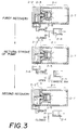
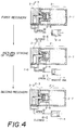
- ink can not satisfactorily be fed to the ink jet recording head 2-2 merely by a single pumping operation achieved by a pump 2-4 of which flow rate is set to a predetermined one. In such case as mentioned above, it is necessary to continuously perform same pumping operations several times in order to compensate the shortage of a pumping capacity.
- the ink 2-5 once sucked in the ink jet recording head 2-2 in the course of each pumping operation is caused to return to an ink reservoir 2-7.
- adequate means for preventing the ink 2-5 from reversely flowing to the ink reservoir 2-7 e.g., a cap 2-6 for retaining the ink pressure in the valve space 2-3 as shown in Figs. 4A to 4C is continuously brought in close contact with the ink jet recording head 2-2 during a series of pumping operations.
- the arrangement of the cap 2-6 with high reliability maintained during the pumping operations prevents the ink jet recording apparatus from being designed with smaller dimensions.
- another problem is that the ink jet recording apparatus is fabricated at an increased cost.
- one proposal is such that a quantity of projecting of a projection from the recording head side toward the porous member is restrictively determined so as to allow the projection to properly come in contact with the porous member.
- Another proposal is such that a plurality of ribs are caused to extend along the inner wall surface of the ink tank cartridge in order to distribute the atmospheric air introduced into the ink tank cartridge via an atmospheric air intake port over the surface of the porous member.
- the ink jet recording apparatus serving as a printer unit is integrally installed in information processing equipment such as a personal computer or the like so that the whole information processing equipment is constructed with smaller dimensions, the real recognition of the foregoing mutual relationship is effectively useful for a projection associated with the ink jet recording apparatus.
- an ink jet container which is attachable to and detachable from a recording head.
- An object of the present invention is to provide an ink tank which assures that ink is stably fed to discharging orifices at a high ink utilization efficiency.
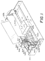
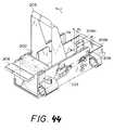
- the ink jet recording apparatus IJRA includes a carriage HC on which an ink jet recording unit IJC is removably mounted.
- the carriage HC includes a pin (not shown) adapted to come in engagement with a spirally extending groove 5005 on a lead screw 5004.
- a driving motor 5013 is rotated in the normal direction or in the reverse direction
- the lead screw 5004 is rotated by the motor 5013 via driving power transmitting gears 5011 and 5009 so as to allow the carriage HC to reciprocally move not only in the a arrow-marked direction but also in the b arrow marked direction.
- reference numeral 5002 designates a thrusting plate for thrusting a recording medium such as a paper, a film for an OHP, a fabric or the like against a platen 5000 within the displacement range of the carriage HC
- reference numerals 5007 and 5008 designate photo-couplers.
- the photo-couplers 5007 and 5008 serve as home position detecting means for optically recognizing the presence of a lever 5006 of the carriage HC so as to shift the direction of the motor 5013 from the normal direction to the reverse direction and vice versa.
- Reference numeral 5016 designates a supporting member for supporting a cap member 404 for capping the front surface of an ink jet recording head therewith, and reference numeral 5015 designated a suction means for sucking in the cap member 404.
- the suction means 5015 evacuates waste ink via an opening 5023 within the cap member 404 so as to recover the ink jet recording head.
- Reference numeral 5017 designates a cleaning blade
- reference numeral 5019 designates a displacing member for displacing the cleaning blade 5017 in the forward/rearward direction.
- the displacing member 5019 is supported by a support plate 5018.
- the configuration of the cleaning blade 5017 should not be limited only to the shown one. Alternatively, any type of conventional cleaning plate may be employed for the same purpose.
- Reference numeral 5012 designates a lever for starting the actuation of the suction means 5015. As a cam 5020 adapted to be engaged with the carriage HC is displaced, the lever 5012 is displaced so as to properly control the driving power of the driving motor 5013 with the aid of hitherto known power transmitting means such as clutch shifting means or the like.
- the lead screw 5005 is rotated so as to allow the carriage HC to assume predetermined positions corresponding to the capping, the cleaning and the sucking as mentioned above.
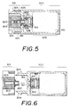
- the ink jet recording unit includes an ink jet recording head 301 and an ink tank cartridge 303 both of which can be separated from each other.
- the ink jet recording unit constructed in that way is employable for the ink jet recording apparatus as shown in Fig. 1.
- a filter 302 is disposed at the intermediate position of a path 320 in the ink jet recording head 301, and an effective pore diameter of the filter 302 is set to 5 to 20 ⁇ m.
- the ink tank cartridge 303 is connected to the ink jet recording head 301 by bringing a pair of arrow-shaped pawls 304 integrally projected from the ink tank cartridge 303 in engagement with the corresponding receiving portions 305 formed in the ink jet recording head 301.
- the arrow-shaped pawls 304 are arranged in the symmetrical relationship so that they are simultaneously engaged with the receiving portions 305.
- an ink feed pipe 315 projecting from the ink jet recording head 301 is engaged with a valve mechanism 311 in the ink tank cartridge 303, causing a valve body 306 to be retracted in the rightward direction as seen in Fig. 5 against the resilient force of a coil spring 312 so as to enable an ink to be fed the ink jet recording head 301 from the ink tank cartridge 303 via the path 320.
- an O-ring 307 disposed around the ink feed pipe 315 seals the joint portion between the ink feed pipe 315 and the valve mechanism 311.
- a cartridge filter 308 is disposed on the upstream side of the valve mechanism 311 in the ink tank cartridge 303.
- An ink reservoir 309 is arranged upstream of the cartridge filter 308 in the ink tank cartridge 303.
- the ink reservoir 309 is constructed such that an ink is impregnated in a porous material 310 received in the ink tank cartridge 303 in the compressed state.
- an ink pressure appearing in discharging orifices 323 of the ink jet recording head 301 is kept negative.
- the ink pressure in the ink tank cartridge 303 is usually kept negative.
- the ink pressure is controlled by utilizing the capillary power of the porous material 310 so as to allow it to be kept negative.
- the valve body 306 is molded of an elastic material such as a rubber or the like so that it is slidably displaceable in the valve mechanism 311.
- an annular sealing portion 313 of the valve body 306 is brought in close contact with a valve body receiving portion 314 around the periphery of an insert hole 321 in the ink tank cartridge 303 by the repulsive force of the coil spring 312 so as to prevent the ink from uselessly flowing out of the ink tank cartridge 303.
- the symmetrical arrangement of a pair of arrow-shaped pawls 304 as mentioned above is simple in structure and effective for assuring that the O-ring 307 stably serves as a sealing member for sealably maintaining the ink passageway in the ink jet recording unit.
- EPDM ethylene-propylene rubber
- the ethylene-propylene rubber exhibits high gas barrier properties, and moreover, it exhibits excellent properties required by the O-ring 307 in respect of ink-resistance, tear-resistance, non-adhesiveness and anti-creeping ability.
- the ink passageway is designed in the above-described manner, i.e., a joint portion is disposed between the ink jet recording head 301 and the ink tank cartridge 303, it is assured that the interior of the ink jet recording unit is reliably kept in the negative pressure state without an occurrence of ink leakage through the joint portion while the ink tank cartridge 303 is connected to the ink jet recording head 301.
- force relationship among the connecting force between the ink jet recording head 301 and the ink tank cartridge 303, the repulsive force of the valve body 306 at the time of connection therebetween, and the disconnecting force of a disconnecting mechanism of the ink jet recording apparatus for disconnecting the ink tank cartridge 303 from the ink jet recording head 301 is represented by the following inequalities.
- Fj - Fv ⁇ Fl Fi >> Fv
- the ink jet recording head 301 is repeatedly connected to and disconnected from the ink tank cartridge 303 for some reason, air is gradually introduced not only into the ink jet recording head 301 but also into the valve mechanism 311 in the ink tank cartridge 303. While the foregoing state is maintained, it is very difficult to continue the recording operation further, since ink can not stably be fed to the ink jet recording head 301 any more.
- the valve mechanism 311 is designed so as to allow the ink path in the valve mechanism 311 to have a very small working volume.
- valve mechanism 311 can easily be restored to the original state by performing a pumping operation therewith even though a preset value Pv representing a volume to be pumped per one stroke of a pump (not shown) of the ink jet recording apparatus.
- a preset value Pv representing a volume to be pumped per one stroke of a pump (not shown) of the ink jet recording apparatus.
- a volume of ink to be pumped per one stroke of the pump is set to 0.1 cc or less.
- a sum of a volume Cv of the valve mechanism 311 and a volume Hv as measured from the inlet port of a path 320 in the ink jet recording head 301 to the filter 302 is designed to be smaller than the volume of ink to be pumped per one stroke by the pump. It is preferable that the sum of the volumes is 0.05 cc or less.
- Fig. 7A shows by way of sectional view the state of the ink jet recording unit before the pumping operation is started. At this time, the ink path in the ink jet recording head 301 and the ink tank cartridge 303 is substantially filled with air. While the foregoing state is maintained, any correct recording operation can not be achieved.
- Fig. 7B to perform a first pumping operation, the pump is operated to suck the ink reservoir via a suction cap 404 such that the ink in the ink reservoir is conducted to the position in excess of the filter 302 in the ink jet recording head 301. At this time, however, the ink does not reach the discharging orifices 323 of the ink jet recording head 301.
- Fig. 7C shows by way of sectional view the flowing state of ink during a next pumping operation.
- the pump Upon completion of the first pumping operation, the pump is restored to the initial state to perform the next pumping operation, and at this time, the suction cap 404 is once disconnected from the ink jet recording head 301.
- the ink filled till the intermediate position of the flow path in the ink jet recording head 301 his caused to return to the ink reservoir 309 held under the negative pressure.
- the ink can not return to the position located upstream of the filter 302 because of the surface tension present over the filter 302 in the ink jet recording head 301.
- Fig. 7D shows by way of sectional view an operational state of the pump when a pumping operation is restarted with the pump. During the restarted pumping operation, it suffices that the short range extending from the filter 302 to the discharging orifices 323 of the ink jet recording head 301 is filled with the ink.
- the ink jet recording head 301 Since the connection of the ink tank cartridge 303 to the ink jet recording head 301 is achieved with the aid of a pair of arrow-shaped pawls 304 fitted into the corresponding receiving portions 305, the ink jet recording head 301 is connected to the ink tank cartridge 303 with very high stability. Thus, there do not arise malfunctions that recorded position are dislocated from the original positions, and moreover, a quality of recording operation is degraded regardless of how often the ink jet recording head 301 and the ink tank cartridge 303 are repeatedly connected to each other and disconnected from each other. It should be added that after the ink jet recording unit is removed from the ink jet recording apparatus, the former can stand as an independent unit.
- a filter 502 is disposed at the foremost end of an ink feed pipe 315 on the upstream side of the latter in an ink jet recording head 301.
- the working volume of a valve mechanism 311 in an ink tank cartridge 303 is determined by satisfying the following equation.
- valve mechanism 311 employed for the ink tank cartridge constructed according to the proceeding embodiments of the present invention will be described below in respect of a structure and a mode of operation thereof with reference to Figs. 9A to 9C.
- Fig. 9A is an exploded perspective view which shows the structure of the valve mechanism 311 to which is not still connected an ink jet recording head. While the foregoing state is maintained, since a valve body 306 is brought in contact with an inner wall surface of the valve mechanism 311 by the repulsive force of a compression coil spring 312, ink does not leak to the outside from the valve mechanism 311.
- the valve mechanism 311 includes a cylindrical member 322 integrated with the top wall of the ink tank cartridge 303 while projecting from the latter, and a filter 308 is secured to the rear end of the cylindrical member 322.
- a stopper 324 is disposed on the downstream side of the filter 308.
- the stopper 324 has an inverted-conical tapered surface 325 formed thereon on the confronting side with the filter 308, and a plurality of communication holes 326 are formed through the stopper 324.
- a plurality of ribs 327 are formed integral with the stopper 324.
- a plurality of axially extending grooves 328 are formed along the inner cylindrical wall of the cylindrical member 322, while a plurality of radially extending grooves 329 are formed inside of an annular sealing portion 313 on the top surface of the valve body 306.
- Fig. 9B shows the operative state of the valve mechanism 311 wherein the valve body 306 is pressed from the outside in the interior of the valve mechanism 311 so as to move in the valve mechanism 311. While the foregoing state is maintained, ink stored in an ink reservoir 309 flows through the filter 308 and then flows outside of the valve mechanism via a space defined between the rear surface of the filter 308 and the stopper 324, a plurality of communication holes 326, a plurality of axially extending grooves 328 and a plurality of radially extending grooves 329.
- the valve mechanism 311 Since the valve mechanism 311 is constructed in the above-described manner, the working volume of the ink path in the valve mechanism 311 can possibly be minimized with high reliability while the reduced movable range of the valve body 306 in the valve mechanism 311 is maintained.
- the previously mentioned volume Cv of the valve mechanism 311 is defined in the following manner. Specifically, the volume Cv represents a volume which remains after a volume corresponding to invasion of the ink feed pipe 315 of the ink jet recording head 301 in the cylindrical member 322 and a volume occupied by the valve body 306, the coil spring 312 and the stopper 324 is subtracted from the interior volume of the cylindrical member 322 located downstream of the filter 308.
- Fig. 9C shows the same operative state of the valve body as that shown in Fig. 9B except that the ink feed pipe 315 of the ink jet recording head 301 is brought in engagement with the valve mechanism 311.
- the filter 502 is secured to the foremost end of the ink feed pipe 315 for the reason as mentioned above.
- the configuration as shown in Fig. 9A is employed for the valve body 306 located opposite to the filter 502, it is obvious that the filter 502 does not obstruct the flowing of ink.
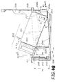
- Figs. 35A to 35C each schematically show by way of perspective view the structure of an ink tank cartridge for an ink jet recording unit to which the present invention is applicable.
- the ink tank cartridges as shown in the figures are constructed so as to be mounted on a carriage of an ink jet recording apparatus in the inverted state, respectively.
- the ink tank cartridge to be connected to the ink jet recording head includes an opening portion (not shown) for feeding ink to the ink jet recording head and an atmosphere communication port (not shown) by way of which the interior of the ink tank cartridge is communicated with the environmental atmosphere.
- the ink tank cartridge includes a pawl portion 1002 serving as a slippage stopper when it is dismounted from the ink jet recording apparatus and a cutout portion 1001 adapted to be engaged with a projection on the ink jet recording apparatus when it is mounted on the latter, at two locations determined so as to correspond to the mounting of the ink tank cartridge in the inverted state.
- Fig. 35A shows by way of perspective view that the cutout portions 1001 are formed inside of the opposite side walls of the ink tank cartridge in order to protect the projection on the ink jet recording apparatus from unexpected collision or the like when the ink tank cartridge is mounted on the ink jet recording apparatus.
- Figs 35B and 35C show likewise by way of perspective views the case that cutout portions 1001 are not formed inside of the opposite side walls of the ink tank cartridge but they are formed along the front edges of the opposite side walls of the same. For this reason, the protective effect attainable with the ink tank cartridge as shown in Fig. 35A can not be expected but the ink tank cartridge can easily be produced.
- the interior of the ink jet recording unit can be maintained in the negative pressure state without an occurrence of malfunction that ink leaks from the connected portion therebetween. Since the ink jet recording head and the ink tank cartridge are stably connected to each other, there does not arise a malfunction that a quality of recording is adversely affected when the ink jet recording head is arbitrarily connected to and disconnected from the ink tank cartridge, and moreover, the ink jet recording unit can easily be exchanged with another one.
- an ink jet recording unit including an ink jet recording head and an ink tank cartridge arbitrarily connectable to and disconnetable from each other wherein the ink tank cartridge can simply be connected to the ink jet recording unit to form an ink flow path and exchangeably disconnected from the ink jet recording unit with the aid of a simple and inexpensive mechanism, and vice vera.
- Fig. 2 is a perspective view of the ink jet recording unit.
- reference numeral 301 designates an ink jet recording head
- reference numeral 303 designates an ink tank cartridge in which ink is stored so that it is fed to the ink jet recording head 301.
- the ink jet recording head 301 includes a plurality of electrothermal converting element (not shown) corresponding to each discharging orifice, and each electrothermal converting element serves to generate thermal energy usable as an energy for causing film boiling with ink so as to allow an ink droplet to be discharged from the corresponding discharging orifice.
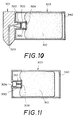
- Fig. 10 is a schematic sectional view of the ink jet recording unit shown in Fig. 2.
- a first filter 302 is disposed in an ink intake port 320 communicated with a plurality of ink discharging orifices 323 via a common ink chamber.
- a porous member 310 having ink impregnated therein is received in the ink tank cartridge 303.
- An ink feed port 330 and an atmosphere communication port 340 are formed through the ink tank cartridge 303.
- a second filter 308 is secured to the ink feed port 330 while coming in close contact with the porous member 310.
- the ink intake port 320 is communicated with the ink feed port 330.
- Both the ink jet recording head 301 and the ink tank cartridge 303 constructed in the above-described manner can be connected to each other and disconnected from each other on a carriage mounted on an ink jet recording apparatus to be described later.
- ink is discharged from the ink discharging orifices 323 so as to effect recording on a recording medium.
- the ink impregnated in the porous member 310 is gradually displaced toward the ink jet recording head 301 by the function of a capillary phenomenon so as to feed the ink to the ink jet recording head 301, and air enters the ink tank cartridge 303 through the atmosphere communication port 340. While the ink impregnated in the porous member 310 is continuously fed to the ink jet recording head 301, dust or similar foreign material in the porous member 310 is seized by the second filter 308.
- any dust does not reach the first filter 302 on the ink jet recording head 301.
- a plurality of ink tank cartridges are repeatedly exchanged one after another in such a manner as to allow one of them to be connected to a single common ink jet recording head 301, there does not arise a malfunction that the first filter 302 is clogged with the dust impregnated in the porous member 310 received in the ink tank cartridge 303.
- ink can stably be fed to the ink jet recording head 301 at all times.
- the second filter 308 is secured to the porous member 308 while coming in close contact with it, ink can stably fed to the ink jet recording head 301 regardless of how often a single ink tank cartridge 303 is repeatedly connected to and disconnected from the ink jet recording head 301.
- a mesh size a of the first filter 302 and a mesh size b of the second filter 308 are determined to establish an inequality of a > b therebetween.
- a screen of the first filter 302 is woven more coarsely than that of the second filter 308. This causes a boundary retaining power on the first filter 302 side to become weaker than that on the second filter 308 side. Consequently, when the ink jet recording head 301 is connected to the ink tank cartridge 303, air is compressed between the first filter 302 and the second filter 308, and subsequently, the compressed air is squeezed in the ink jet recording head 301 side via the first filter 302.
- the air squeezed in the ink jet recording head 301 side is sucked to the outside from the ink discharging orifices 323 by the function of an ink suction recovering activity to be achieved when the ink jet recording head 301 is connected to the ink tank cartridge 303.
- the first filter 302 is designed to be smaller than the second filter 308 so that an area of the first filter 302 becomes smaller than that of the second filter 308.
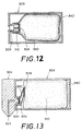
- FIG. 11 An ink tank cartridge usable with the present invention will be described below with reference to Fig. 11. Since an ink jet recording head (not shown) is substantially coincident in structure as described before, illustration of the ink jet recording head is eliminated in Fig. 11. For this reason, merely an ink tank cartridge 303 is shown in the drawing.
- a valve body 306 normally biased by a coil spring 312 is disposed in the ink tank cartridge 303 so as to close an ink feed port 330 with the valve body 306 by the resilient force of the coil spring 312.
- the ink feed port 330 is closed with the valve body 306.
- the valve body 306 is displaced in the rightward direction as seen in the drawing against the resilient force of the coil spring 312 until the ink feed port 330 is opened.
- a flexible bag 350 which replaces porous member 310, having ink stored therein is received in the ink tank cartridge 303 which is entirely coincident with the ink tank cartridge 303 in structure described above with reference to Fig. 11.
- Other structure rather than the aforementioned one is same to that in Fig. 11.
- a first circular filter 302 is positionally offset from a second filter 308 as viewed in the vertical direction in Fig. 13.
- the centers of both the first and second filters 302 and 308 are not located in the concentric relationship relative to each other.
- Other structure rather than the aforementioned one is same to that in Fig. 10.
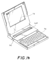
- Fig. 14 shows by way of perspective view an outline of appearance of an information processing unit 74 having the ink jet recording apparatus (to serve as a printer section) installed therein.
- reference character IJP designates a printer section
- reference numeral 72 designates a key board including not only keys for inputting characters, numerals or the like thereinto but also keys for outputting various kinds of commands therefrom
- reference numeral 73 designates a display section including a display board.
- Fig. 15 is a block diagram which shows the structure of electrical circuits arranged in the information processing unit 74.
- reference numeral 81 designates a controller for executing main control
- reference numeral 82 designates a central processing unit designed in the form of a microcomputer
- reference numeral 83 designates a random access memory including a working area for developing text data and image data
- reference numeral 84 designates a read only memory having a working program and fixed data such as font data or the like stored therein
- reference numeral 85 designates a timer for governing an execute cycle for the central processing unit 82 and a timing relationship required when a recording operation is performed by the printer section IJP
- reference numeral 86 designates an interface portion by way of which signals transmitted from the central processing unit 82 are outputted into peripheral equipment.
- reference numeral 87 designates a controller for the printer section IJP
- reference numeral 88 designates a head driver for delivering recording signals and electricity to an ink jet recording head H mounted on an ink jet recording unit
- reference numerals 89a and 89b designate motor drivers for delivering signals and electricity required for driving a carriage motor 102a and a conveyance motor 102b
- reference numeral 90 designates a carriage sensor for detecting the position of a carriage HC to determine whether the carriage HC is located at a home position or not
- reference numeral 91 designates a paper sensor for detecting the presence or the absence of a recording medium P so as not to allow any recording to be effected in the region other than a recording medium P (paper) when the recording medium P is not inserted into the printer section IJP or a recording operation is completed to reach the terminal end of the recording medium P.
- reference numeral 74 designates an external storage unit such as a floppy disc drive, a hard disc drive, a random access memory card or the like
- reference numeral 75 designates an external interface portion for making communication with another information processing unite or controlling peripheral equipments while making connection directly to buses disposed inside of each peripheral equipment.
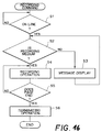
- the program starts from Step S1 in which the controller 81 determines whether the display actuating section is turned on or not. Mainly, in response to an instruction transmitted from the outside for starting a recording operation via a communication system, the controller 81 executes the processing so as not to allow a recording operation to be started while the printer section IJP is not ready to perform the printing operation. When the controller 81 determines that the display actuating section is turned on, the program goes to Step S2.
- Step S2 in response to a signal outputted from the paper sensor 91, the controller 81 determines whether a recording medium P is inserted into the printer section IJP or not.
- the determination to be made by the controller 81 in Step S2 is intended to prevent an occurrence of malfunction that the printer section IJP such as an ink jet recording unit or the like is contaminated with scattered ink when the printing operation is started without any recording medium inserted into the printing section IJP or ink serving as a recording agent is uselessly consumed.
- the controller 87 may determine in Step S2 not only whether the printing medium P is present or absent but also whether each pinch roller and each conveying roller are held in the released state or not. This determination to be made in Step S2 is intended to prevent an occurrence of malfunction that the recording medium P is incorrectly conveyed when each pinch roller is held in the released state even though the recording medium P is inserted into the printer section IJP.
- the controller 87 can determined with the aid of, e.g., a mechanical switch disposed on a release lever whether each pinch roller is held in the released state or not. In the case that the controller 87 determines that the recording medium P is not correctly inserted into the printer section IJP, the program goes to Step S3.
- Step S3 the controller 87 issues a message or an instruction to an operator that he should pay more attention to the printing section IJP so as to allow the recording medium P to be correctly inserted into the printing section IJP.
- a message or an instruction may be given to him by turning on the display actuating section so as to activate a lighting device to generate a light beam with a lamp or activate a buzzer to generate sound therewith.
- Step S4 a recording operation is started with the printer section IJP.
- the head driver 88 is activated to drive the printer section IJP.
- the motor drivers 89a and 89b drive the carriage motor 102a and the conveying motor 102b so as to perform a printing operation with the printer section IJP by displacing the carriage HC in the main scanning direction, displacing the recording medium P in the auxiliary scanning direction and cleaning the recording head H.
- Step S5 in which in response to a signal outputted from the central processing unit 82, the controller 87 instructs that the recording operation is completed.
- the controller 87 determines that the number of recorded lines as measured in the space of a single page in the auxiliary direction reaches a predetermined value or when the paper sensor 91 detects that the recording operation is completed in the recording range on the recording medium P, the controller 87 determines that the recording operation is completed with the recording medium P.
- Step S6 the controller 87 activates the carriage HC so as to return it to the home position.
- This is intended to cap the recording head H with a suitable capping member so as to protect the ink discharging surface of the recording head H from damage or injury before the supply source is turned off on completion of the recording operation.
- the recording medium P is discharged from the printer section IJP by driving the conveyance motor 102b until it is confirmed that the conveyance motor 102b is driven by a predetermined number of revolutions or until the paper sensor 91 detects that the recording medium P is discharged from the printer section IJP.
- the controller 81 instructs the central processing unit 82 so as to allow the latter to activate the display actuating section or output an instruction to the peripheral equipments via the external interface portion 75, whereby the recording operation is completed.
- an ink jet recording head and an ink tank cartridge can be connected to each other and disconnected from each other. Since the printer section IJP is constructed such that a connecting operation or a disconnecting operation can be achieved while an assembly of the recording head and the ink tank cartridge is mounted on the carriage HC or dismounted from the same, advantageous effects as noted below can be obtained.
- the ink tank cartridge is mounted on the carriage HC, there does not arise a necessity for extending or arrange a tube for the purpose of feeding ink to the ink jet recording head, resulting in the recording section IJP being constructed with small dimensions.
- the whole assembly of the ink jet recording head and the ink tank cartridge is exchanged with a new one but merely the ink tank cartridge is to be exchanged with a new one with the result that the printer section IJP can be operated at a reduced running cost.
- the ink jet recording head and the ink tank cartridge are unavoidably disconnected from each other on the carriage HC, since the position where a certain intensity of force is applied to the ink tank cartridge is specifically determined on the ink tank cartridge, it is required that merely a part of the ink tank cartridge corresponding to the foregoing position is designed to have a large thickness enough to stand against the applied force and the other part of the ink tank cartridge is designed to have small thickness.
- the ink tank cartridge can be constructed with a reduced weight but with an increased interior volume thereof.
- FIG. 17 is a cross-sectional view of the ink tank cartridge 303 taken along a plane in parallel with the front end surface having the ink outlet port formed thereon.
- the ink tank cartridge 303 includes a plurality of longitudinally extending ribs 371, 372, 373 and 374 on the right-hand side wall, the lower wall, the left-hand side wall and the upper wall thereof, respectively.
- the porous member 310 is employed for the ink tank cartridge 303 having a comparatively large volume.
- the air can easily be substituted for the ink contained in the porous member 310 as the contacting area defined by both the inner wall of the ink tank cartridge 303 and the porous member 310 is reduced more and more resulting in reducing the remaining ink in the porous member 310. Since a plurality of ribs are arranged around the inner wall of the ink tank cartridge 310 in the above-described manner, the air can uniformly be distributed over all the surfaces exclusive of the surface having the ink outlet port formed thereon, resulting in the ink contained in the porous member 303 being utilized at a highly improved efficiency.
- each of the ribs 371, 372, 373 and 374 may variably be determined in consideration of various working conditions given to the ink tank cartridge 303.
- the ribs 372 formed on the lower wall of the ink tank cartridge 303 are dimensioned to have the height lower than that of the other ribs. This is intended to easily recover by absorbing the leaked ink in the small space between the lower wall of the ink tank cartridge 303 and the porous member 310 when some ink flows outside of the porous member 310 due to some abnormality and it is then stored in the foregoing small space.
- the respective ribs 371, 372, 373 and 374 may be designed such that the height of each rib is varied, and moreover, each rib is tapered toward the ink outlet port side from the air intake port side with some height difference therebetween in order to change compressibility of the porous member 310 across the length of the ink tank cartridge 303 so as to allow the ink to be concentratively collected in a certain region in the porous member 310.
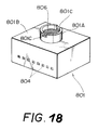
- Fig. 18 shows by way of perspective view a type of ink jet recording head section 801 including a connecting portion 801A.
- reference numeral 801C designates a cutout portion which is formed at the end of the cylindrical connecting portion 801A.
- the ink jet recording head section 801 is connected to the opponent ink tank cartridge, a liquid chamber 807 in the ink jet recording head portion 801 is communicated with the interior of the ink tank cartridge 802 via the cutout portions 801C so as to feed ink to the ink jet recording head section 801.
- Fig. 19 shows by way of sectional view an ink jet recording unit
- an exchangeable type ink tank cartridge 820 of the above-proposed type having no ink absorbing member received therein is connected to an ink jet recording head section 801.
- No connecting member is disposed therebetween, and an elastic sealing member 825 is disposed on the opposing surface 820B of the ink tank cartridge 820.
- the ink jet recording head section 801 can be connected directly to the ink tank cartridge 820 without any necessity for disposing a connecting member.
- An ink bag 822 molded of a film of high molecular material is received in the ink tank cartridge 820.
- the ink bag 822 is fused to a flange portion 823 of the ink tank cartridge 820, and ink 811 is filled in the ink bag 822.
- An annular groove 824 is formed on the opposing surface 820A of the ink tank cartridge 820 so that an elastic sealing member 825 such as an O-ring or the like is fitted into the annular groove 824.
- a negative pressure adjusting valve 826 is disposed in an atmospheric air communication port 809.
- the negative pressure adjusting valve 826 is composed of a large circular valve seat 827 having a ventilation hole 826A formed therethrough and a circular seat 828 coated with an oil such as a silicone oil or the like hardly dried but having excellent viscosity in such a manner as to close the ventilation hole therewith from inside. Similar to the seat 828, the outer peripheral part of the large seat 827 is coated with the same oil as mentioned above so that it comes in close contact with the outer wall surface of the ink tank cartridge 820.
- the seat 827 is parted away from the outer wall surface of the ink tank cartridge 820 against the adhering force of the oil so that the air having the increased pressure is exhausted to the outside.
- the ink tank cartridge 820 constructed in the above-described manner, there is a possibility that an excessively high magnitude of shock is applied to the ink tank cartridge 820, causing the ink 811 to leak, when the ink jet recording head section 801 is disconnected from the ink tank cartridge 820.
- a valve 830 is disposed in the ink tank cartridge 820.
- valve body 830 is molded of a rubber such as a chlorided butyl rubber, EPDM or the like.
- the valve body 830 is normally biased toward a connection port 820A by the resilient power of a coil spring 831 until it comes in close contact with the connection port 820A so as to prevent ink from leaking from the ink bag 822. While the ink tank cartridge 820 is connected to the ink jet recording head section 801 as shown in Fig.
- an ink feed port 801A of the ink jet recording head section 801 is brought in contact with the valve body 830 which in turn is inwardly thrusted, causing a certain annular gap to be formed around the valve body 830, whereby an ink chamber 807 of the ink jet recording head section 801 is communicated with the ink bag 822 via the cutout portions 801C formed on the connecting portion 801A (see Fig. 18).
- a length of projecting of the connecting portion 801A is determined to be long enough to allow the valve body 820 to be retracted against the resilient force of the coil spring 831 until an annular gap is formed around the value body 830 to serve as an ink path. Rather, it is desirable that the valve body 830 can not deeply be thrusted into the interior of the ink tank cartridge 820 due to the arrangement of the coil spring 831.
- ink tank cartridge 820 constructed in that way, a large quantity of ink 811 can be stored in the ink bag 822 compared with the predetermined inner volume of the ink tank cartridge 820, and moreover, only a small quantity of ink 811 remains in the ink tank cartridge 820 on completion of recording operations, resulting in a volume utilization efficiency of 60 to 70 % being obtainable with the ink tank cartridge 820.
- the ink tank cartridge 820 has a drawback that it is unavoidably produced at an expensive cost compared with an ink tank cartridge of the type including an absorbing member, since it is difficult that the ink bag 822 is fusibly secured to the flange portion 823, resulting in it being produced with many molding steps, the negative pressure adjusting valve 826 is required for the purpose of properly controlling the negative pressure in the ink tank cartridge 820, the valve body 830 is required for the purpose of preventing an occurrence of ink leakage, and moreover, the ink bag 822 is molded in a complicated configuration having a smaller working inner volume smaller than that of an ordinary one.
- the ink tank cartridge of the foregoing type has the aforementioned advantageous effects, it is desirable that one of two types of ink tank cartridges is selectively used depending on the application field thereof.
- a length of projecting of the connecting portion 801A of the ink jet recording head section 801 is possibly shortened.
- a joint attachment such as the connecting member is disposed therebetween in order to variably determine a length of projecting of the connecting portion 801A.
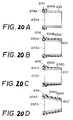
- connecting members for connecting an ink tank cartridge 802 to the opponent ink jet recording head section are shown in Figs. 20A to 20D, Fig. 21A and Fig. 21B, respectively.
- Fig. 20A shows by way of sectional view a cylindrical connecting member 833 including an elastic sealing member 834 having a square sectional shape.
- a front surface 834A of the sealing member 834 comes in close contact with an opposing surface 801B of the ink jet recording head section 801, while a rear surface 834B of the same comes in close contact with an opposing surface 802B of the ink tank cartridge 802, whereby the ink jet recording head section 801 and the ink tank cartridge 802 are liquidtightly connected to each other with the sealing member 834 interposed therebetween.
- Fig. 20B shows by way of sectional view a connecting member 833 which is modified from the connecting member 833 shown in Fig. 20A such that a part of the sealing member 834 extends from the rear surface 834B in the axial direction.
- An outer peripheral surface portion 834C of the sealing member 834 is press-fitted into a cylindrical connecting portion 810 of the ink tank cartridge 802 so that the connecting member 833 is fitted into the ink tank cartridge 802 with improved sealability.
- Fig. 20C shows by way of sectional view a connecting member 833 which is modified from the sealing member 833 shown in Fig. 20B such that an outer peripheral surface portion 834D of the sealing member 834 is tapered in the rightward direction so as to enable the connecting member 833 to be easily fitted into the ink tank cartridge 802.
- FIG. 20D shows by way of sectional view a connecting member 833' which is modified from each of the connecting members 833 shown in Fig. 20A to Fig. 20C such that it is tapered in the rightward direction, and moreover, it is sheathed with an elastic sealing member 834 across the whole axial length from the front end 833'A of the connecting member 833' to the rear end of the same.
- reference numeral 834E designates an outer peripheral surface portion of the sealing member 834 which is molded corresponding to the outer peripheral surface of the connecting member 833' so as to serve in the same manner as the sealing member 834 shown in Fig. 20C.
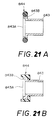
- Figs. 21A and 21B each shows by way of sectional views a connecting member which is preferably employable in the case that an elastic sealing member is firmly disposed on the ink jet recording head section side as will be described later.
- a connecting member which is preferably employable in the case that an elastic sealing member is firmly disposed on the ink jet recording head section side as will be described later.
- the elastic sealing member (not shown) disposed around an ink feed port of the ink jet recording head section 801 interferes with the connecting member.
- a part of the connecting member on the connecting side relative to the ink jet recording head section 801 is designed to have an enlarged diameter.
- reference numeral 843 designates a connecting member having a stepped part formed thereon
- reference numeral 843A designates a front end of the connecting member 843
- reference numeral 843B designates a flange portion having an enlarged inner diameter to form a stepped part of the connecting member 843.
- annular retaining groove 843C is formed around the outer periphery of the flange portion 843B so that an O-ring type elastic sealing member 844 having a diameter larger than the flange portion 843B is fitted around the annular retaining groove 843C.
- annular elastic sealing member 844 having a L-shaped sectional contour is fitted around the flange portion 843B.
- the connecting member 843 including the flange portion 843B as shown in Fig. 21B is employable for an ink jet recording unit.
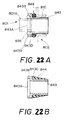
- FIGs. 22A and 22B show by way of sectional views a connecting member constructed according to another modified embodiment of the present invention.
- the connecting member 843 includes a flange portion 843B in the same manner as that shown in Figs. 21A and 21B.
- an O-ring type elastic sealing member 844 is fitted around the flange portion 843B of the connecting member 843 as well as a cylindrical stepped portion 843D of the same.
- Fig. 22A an O-ring type elastic sealing member 844 is fitted around the flange portion 843B of the connecting member 843 as well as a cylindrical stepped portion 843D of the same.
- a conically extending elastic sealing member 844 is fitted around the stepped portion 843D of the connecting member 843 within the range extending from the rear surface of the flange portion 843B to the foremost end of the same so that the connecting member 843 is liquidtightly press-fitted into the ink tank cartridge 802.
- the connecting member including an elastic sealing member in the above-described manner, e.g., in the case shown in Fig. 22A, the space between the connecting member 843 and the ink tank cartridge 802 is sealed with an elastic sealing member 844, while the space between the connecting member 843 and the ink jet recording head section 801 is sealed with the elastic sealing member 835 fitted around the ink feed port 801A of the latter.
- the present invention has been described above with respect to the case that a connecting member is used for an exchangeable assembly of the ink jet recording head section 801 and the ink tank cartridge 802 but the present invention should not be limited only to this case.
- the present invention may equally be applied to the case that the ink jet recording head section 801 is integrally connected to the ink tank cartridge 802 with the aid of the connecting member. In other words, it is not always necessary that the ink jet recording head section 801 can be disconnected from the ink tank cartridge 802.
- an ink jet recording head section can be connected to an ink tank cartridge via a tubular connecting member including an elastic sealing member so as to sealably close the space therebetween with the sealing member, the arrangement of the connecting member makes it possible that a common ink jet recording head section can arbitrarily be connected to a different type of ink tank cartridge.
- one of a plurality of ink tank cartridges each containing a different kind or color of ink can be connected to the common ink jet recording head section as desired depending on a utilization field of the ink jet recording unit. Consequently, the utilization field of the ink jet recording unit to which the present invention is applied can substantially be widened.
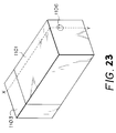
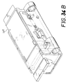
- Fig. 23 is a perspective view of the ink jet recording unit including an ink jet recording head 1103 and an ink tank cartridge 1101 both of which are integrated with each other, and Fig. 24 is a sectional view of the ink jet recording unit taken along line X - Y in Fig. 23.
- an ink absorbing member 1102 made of a sponge-like material is housed in the ink tank cartridge 1101, and an ink outflow port 1105 adapted to receive a projection 1104 of the ink jet recording head 1103 therein and an atmospheric air intake port 1106 by way of which atmospheric air is taken so as to allow it to be substituted for the ink contained in the ink absorbing member 1102 as the ink is increasingly consumed are formed through the ink tank cartridge 1101.
- the space between the ink tank cartridge 1101 and the ink jet recording head 1103 is sealably closed with a rubber member 1111.
- the ink absorbing member 1102 is compressed with side walls 1107 each extending at a right angle relative to the surface having the ink outflow port 1105 formed thereon, whereby an ink retaining power of the ink absorbing member 1102 is restrictively retained by the side walls 1107.
- a part of the ink absorbing member 1102 is compressed by the projection 1104 of the ink jet recording head 1103, and a meniscus power appearing at the foregoing part is set to be larger than that in the other part of the ink absorbing member 1102 compressed by the side walls 1107.
- a meniscus power appearing at the foregoing part is set to be larger than that in the other part of the ink absorbing member 1102 compressed by the side walls 1107.
- a filter 1108 is secured to a part of the ink absorbing member 1102 adapted to come in contact with the foremost end of the projection 1104 projecting from the ink jet recording head 1103, in order to prevent dust or similar foreign materials in the ink from flowing into the ink jet recording head 1103.
- the ink As the ink is taken from the ink absorbing member 1102 through the filter 1108, it flows through an ink flow path 1109 to reach an ink discharging orifice 1110 so that it is discharged from the orifice 1110 to a recording medium such as a paper or the like in the a arrow-marked direction by actuating ink discharging means (not shown).
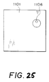
- Fig. 25 is a rear view of the ink jet recording unit as seen from the rear side where the atmospheric air intake port 1106 is formed through the ink tank cartridge 1101 on the ink jet recording unit shown in Fig. 23 and Fig. 24.
- the atmospheric air intake port 1106 is molded as an independent component in consideration of the conveniences for molding the ink tank cartridge 1101 of a synthetic resin by employing, for example, an injection molding process.
- the ink jet recording unit constructed in the above-described manner, as a part of the ink absorbing member 1102 is compressed by the projection 1104 of the ink jet recording head 1103, the meniscus power having an intensity higher than that appearing in the other part of the ink absorbing member 1102 arises at the foregoing part of the latter, causing the ink contained in the ink absorbing member 1102 to be continuously displaced to the ink outflow port 1105 without any possibility that feeding of the ink is interrupted in the course of each recording operation.
- the atmospheric air intake port 1106 is usually designed in a complicated manner with a plurality of chambers arranged therein to divide the interior of the atmospheric air intake port 1106 into a plurality segments, and it is inserted into the ink tank cartridge 1101 by a certain distance.
- the volume of the ink tank cartridge 1101 is reduced so as to meet a requirement for designing a printer with small dimensions, it is necessary that in spite of the small volume of the ink tank cartridge 1101 itself, the volume of the ink absorbing member 1102 is enlarged as far as possible so that a possibly large quantity of ink is contained in the ink absorbing member 1102.
- a part of the atmospheric air intake port 1106 located inside of the ink tank cartridge 1101 comes directly in contact with a porous material such as a sponge or the like constituting the ink absorbing member 1102, causing the ink absorbing member such as at 1102 to be locally intensely compressed by the atmospheric air intake port 1106.
- the meniscus power arising in the ink absorbing member at 1112 in the vicinity of the atmospheric air intake port 1106 is enlarged not only in excess of thee meniscus power caused by restrictively compressing the ink absorbing member 1102 with the side walls 1107 of the ink tank cartridge 1101 but also in excess of the meniscus power caused by compressing the ink absorbing member 1102 with the projection 1104 of the ink jet recording head 1103. This may lead to the result that the ink remaining in the ink absorbing member 1102 as it is increasingly consumed is irregularly distributed in the ink absorbing member 1102.
- the ink is liable to remain in the vicinity of the atmospheric air intake port 1106, resulting in an ink utilization efficiency of the ink tank cartridge 1101 being degraded.
- the ink jet recording unit Due to the fact that the ink is liable to remain in the vicinity of the atmospheric air intake port 1106 as mentioned above, the ink jet recording unit has the case that the ink readily invades in the atmospheric air intake port 1106 in the case that the ink tank cartridge 1101 is exposed to a high temperature during transportation of the ink jet recording unit or in the case that a temperature cycle ranging from a low temperature to a high temperature is repeated with the ink jet recording unit.
- an ink jet recording unit constructed according to embodiments of the present invention which can improve ink utilization efficiency of an ink tank cartridge more effectively will be described below.
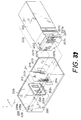
- Fig. 26 is a perspective view thereof.
- the ink jet recording unit includes an ink jet recording head 1203 and an ink tank cartridge 1201 both of which are integrally connected to each other in the shown case but disconnected from each other as desired.
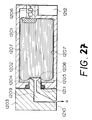
- Fig. 27 is a sectional view of the ink jet recording unit taken along line X - Y in Fig. 26, and
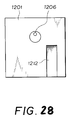
- Fig. 28 is a rear view of the ink jet recording unit as viewed from the rear side where an atmospheric air intake port 1206 is formed on the ink tank cartridge 1201.
- an ink absorbing member 1202 made of a sponge or the like is received in the ink tank cartridge 1201, and an ink outflow port 1205 adapted to receive a projection 1204 projecting from the ink jet recording head 1203 and an atmospheric air intake port 1206 through which atmospheric air is quickly taken therein so as to allow the introduced air to be substituted for ink contained in the ink absorbing member 1202 as the ink is increasingly consumed are formed through the ink tank cartridge 1201.
- the space between the ink tank cartridge 1201 and the ink jet recording head 1203 is sealably closed with an elastic sealing member 1211 molded of a rubber or the like.
- the ink absorbing member 1202 is compressed by side walls 1207 extending at a right angle relative to the front surface having the ink outflow part 1205 formed thereon on the ink tank cartridge 1201, causing the ink retaining power of the ink absorbing member 1202 to be restrictively maintained by both the side walls 1207.
- the projection 1204 of the ink jet recording head 1203 is brought in contact with a part of the ink absorbing member 1202 to compress the foregoing part therewith, and the meniscus power arising in the foregoing part is set to be larger than that appearing in the other part of the ink absorbing member compressed mainly by both the side walls 1207.
- the ink contained in the ink absorbing member 1202 is continuously displaced to the ink outflow port 1205 as it is consumed. Thus, there does not arise a malfunction that feeding of the ink is interrupted during each recording operation.
- a filter 1208 is secured to the projection 1204 of the ink jet recording head 1203 at which the foregoing part of the ink absorbing member 1202 comes in contact therewith so as to prevent dust or similar foreign materials in the ink absorbing member 1202 from flowing into the ink jet recording head 1203.
- the ink As the ink is taken from the ink absorbing member 1202 through the filter 108, it flows through an ink flow path 1209 to reach an ink discharging orifice 1210 so that it is discharged from the ink discharging orifice 1210 to a recording medium such as a paper or the like in the a arrow-marked direction by actuating ink discharging means (not shown).
- a cutout portion 1212 (serving as a projection relative to the ink absorbing member 1202) is formed below the atmospheric air intake port 1206 on the rear surface of the ink tank cartridge 1201 having the atmospheric air intake port 1206 formed thereon.
- a part of the ink tank cartridge 1201, i.e., the space located below the atmospheric air intake port 1206 is removed by forming the cutout portion 1212 in that way.
- the arrangement of the cutout portion 1212 in the above-described manner makes it possible to prevent an occurrence of the hitherto known malfunction that the ink absorbing member 1202 is excessively compressed by the atmospheric air intake port 1206.
- the contact pressure induced by bringing a part of the atmospheric air intake port 1206 in close contact with the ink absorbing member 1202 can be attenuated by the arrangement of the cutout portion 1212.
- the ink absorbing member 1202 comes in close contact not only with the atmospheric air intake port 1206 but also with the cutout portion 1212 with an increased contact area.
- an occurrence of local excessive compression of the ink absorbing member 1202 can reliably be prevented with the aid of the cutout portion 1212.
- the cutout portion 1212 is arranged on the rear side of the ink tank cartridge 1201 where the atmospheric air intake port 1206 is formed through the ink tank cartridge 1201, a largest quantity of ink can be filled in the ink tank cartridge 1201 in spite of the reduced interior volume of the latter without irregular distribution of the ink in the ink absorbing member 1202 caused as the ink is increasingly consumed.
- ink utilization efficiency of the ink tank cartridge 1201 can be improved with the ink jet recording unit constructed in the above-described manner.
- the ink container of the present invention can reliably prevent an occurrence of malfunction that the ink undesirably invades in the atmospheric air intake port 1206 and then leaks outside of the ink tank cartridge 1201 through the atmospheric air intake port 1206 in the case that the ink jet recording unit is exposed to a high temperature during transportation thereof or in the case that a temperature cycle ranging from a low temperature to a high temperature is repeated with the ink jet recording unit.
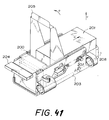
- Figs. 29 to 31 show by way of rear views the structure of an ink container constructed according to the present invention.
- reference numerals 1312, 1412 and 1512 designate cutout portions, respectively.
- the cutout portion 1321 is formed on the rear surface of an ink tank cartridge 1301 having an atmospheric intake port 1306 formed thereon
- the cutout portion 1412 is formed on the rear surface of an ink tank cartridge 1401 having an atmospheric air intake port 1406 formed thereon
- the cutout portion 1502 is formed on the rear surface of an atmospheric air intake port 1506 formed thereon.
- the cutout portion 1312 has a wide width as if the cutout portion 1212 shown in Fig. 28 is transversely enlarged as it is.
- the cutout portion 1412 substantially same to the cutout portion 1212 shown in Fig. 28 is formed at the central part of the ink tank cartridge 1401.
- the cutout portion 1512 is formed at the position away from the atmospheric air intake port 1506, i.e, on the left-hand side of the ink tank cartridge 1501 as seen in Fig. 31.
- the arrangement of the cutout portion 1312, 1412, 1512 shown in Figs. 29 to 31 makes it possible to enlarge an area of the compressed part of an ink absorbing member (not shown) compressed by bringing the ink absorbing member in close contact with the atmospheric air intake port 1306, 1406, 1506 as well as the cutout portion 1312, 1412, 1512, respectively.
- the cutout portion 1312, 1412, 1512 there does not arise a malfunction that a part of the ink absorbing member is locally excessively compressed only by the atmospheric air intake port 1306, 1406, 1506.
- the cutout portion 1312, 1412, 1512 is arranged along the rear surface of the ink tank cartridge 1301, 1401, 1501 having the atmospheric air intake port 1306, 1406, 1506 formed thereon, a largest quantity of ink can be filled in the ink tank cartridge 1301, 1401, 1501 having a reduced inner volume without an occurrence of irregular dispersion of the ink in the ink absorbing member caused as the ink is increasingly consumed.
- ink utilization efficiency of the ink tank cartridge 1301, 1401, 1501 can be improved with the ink jet recording unit.
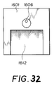
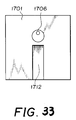
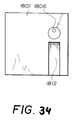
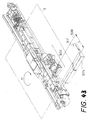
- an atmospheric air intake port 1606, 1706, 1806 is formed at the central location of an ink tank cartridge 1601, 1701, 1801, respectively.
- a cutout portion 1612, 1712, 1812 is arranged on the rear surface of the ink tank cartridge 1601, 1701, 1801 having the atmospheric air intake port 1606, 1706, 1806 formed thereon.
- a quantity of projecting of the atmospheric air intake port is substantially equalized to a depth of the cutout portion as measured inside of the rear surface of the ink tank cartridge, and this depth of the cutout portion is determined within the range where the advantageous effects of the ink jet recording unit are assured. Therefore, both the factors, i.e, the quantity of projecting of the atmospheric air intake port and the depth of the cutout portion may slightly be different from each other, provided that the advantageous effects of the ink jet recording unit are not degraded.
- the present invention has been described above with respect to the embodiments wherein the ink tank cartridge is exchangeably connected to an ink jet recording head (not shown). Alternatively, the present invention may equally be applied to the case that the ink tank cartridge is integrally connected to an ink jet recording head without any loss of the foregoing advantageous effects.
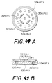
- reference character (F) designates a plane of a stopper ST along which an end filter F is supported.
- a plurality of through holes P2 (twelve holes in the shown case) each having a diameter larger than a mesh size of the end filter F are arranged in the equally spaced relationship as seen in the circumferential direction with the center O of the end filter F as a center, and another through hole P1 having the same diameter as that of each hole P2 is formed through the center of the stopper ST.
- the stopper ST has a flattened inverted conical sectional shape which is contoured such that a distance between the stopper and the end filter F is gradually increased toward the center of the end filter F from the periphery of the same to form a conical space therebetween so as to allow the liquid to be temporarily stored therein.
- reference character R1 designates a plurality of ribs each serving to suppress the displacement of the end filter F.
- the contact range where the end filter F comes in contact with the porous member SP exhibits a circular shape of which center is positionally coincident with the center axis of the ink tank cartridge.
- an upper wall US of the container and a lower wall LS of the same each serving as a symmetrical plane are spaced away from the outer periphery of the contact range of the end filter F by a shortest distance X.
- a side wall SLS of the container and a side wall SRS of the same each serving as a symmetrical plane are spaced away from the outer periphery of the contact range of the end filter F by a shortest distance Y.
- the shortest distance X assumes a value of 4.2 mm, while the shortest distance Y assumes a value of 2.9 mm.
- the foregoing shortest distance X is slightly larger than a radius of 4 mm of the end filter F.
- the shortest distance X is increased in excess of the radius of the end filter F by a quantity of 5 %.
- this sabstantial distances X and Y are less than the effective diameter actually, a half of the effective diameter ⁇ 1.3) of the end filter F. For this reason, the porous member SP is substantially affected by the contact range of the end filter F.
- the porous member SP is dimensioned with respect to a parallelepiped-shaped configuration such that the working sectional area of the porous member SP inclusive of the contact range of the end filter F is represented by a width of 28 mm ⁇ a height of 30 mm in the non-compressed state but it is represented by a width of 13.8 to 15.8 mm ⁇ a height of 16.4 mm in the compressed state wherein the whole surface of the porous member SP is compressed by the periphery of the container.
- a compression ratio of the porous member SP can be expressed by (13.5 to 15.8)/28 in the transverse direction, 16.4/30 in the vertical direction, and 23/35 in the longitudinal direction.
- the compression ratio in the longitudinal direction is smaller than the compression ratio in the transverse direction as well as the compression ratio in the vertical direction, and the compression ratio in the transverse direction is substantially equal to the compression ratio in the vertical direction.
- a difference between the compression ratio in the longitudinal direction and the compression ratio in the circumferential direction lies within the range of 0.09 or more to 0.18 or less, while a difference between the compression ratio in the transverse direction and the compression ratio in the vertical direction lies within the substantially same range as mentioned above.
- Figs. 37 to 48 schematically show a mechanism advantageously employable for fitting the liquid storage container of the present invention to a specific carriage.
- reference numeral 200 designates an ink jet recording head for discharging ink in response to an electrical signal
- reference numeral 201 designates an ink tank cartridge in which the ink is stored and then fed to the ink jet recording head 200
- reference numeral 203 designates a carrier which is mounted on an ink jet recording apparatus for holding the ink jet recording head 200 and the ink tank cartridge 201 for the purpose of performing a scanning operation
- reference numeral 204 designates a head lever for holding the ink jet recording head 200 and releasing it from the held state
- reference numeral 205 designates an ink tank lever for connecting the ink tank cartridge 201 to the ink jet recording head 201 and disconnecting the former from the latter
- reference numeral 207 designates a head holder spring for firmly holding the ink jet recording head 200 on the carrier 203
- reference numeral 208 designates an ink tank case
- Fig. 37 shows by way of perspective view the arrangement of the ink jet recording head 200 and the ink tank cartridge 201.
- reference numeral 220 designates an ink receiving sleeve which has a hole formed therein to serve as a path for feeding ink to the ink jet recording head 200
- reference numeral 221 designates an ink feeding hole through which ink is fed from the ink tank cartridge 201 to the ink jet recording head 200
- reference numeral 222 designates a connection pawl which serves as guiding means for holding thee ink jet recording head 200 and the ink tank cartridge 201 when they are integrally connected to each other
- reference numeral 223 designates a guide groove for guiding and engaging the connection pawl 222
- reference numeral 232 designates a head tab for easily performing a taking-out operation when the ink jet recording head 200 is taken out of the carrier 203.
- An ink jet recording unit 202 is constructed by the aforementioned components.
- the ink jet recording head 200 includes a plurality of electrothermal converting elements for generating thermal energy to be utilized for discharging ink, a substrate having a driving circuit formed thereon for driving the electrothermal converting elements, a plurality of discharging orifices and ink paths which are formed on the sabstrate corresponding to the electrothermal converting elements, and a ceiling plate having a common ink chamber formed therein to make communication with the ink paths.
- the foregoing components are arranged one above another to build a laminated structure.
- the ink jet recording head 200 includes electrical contact by way of which a signal outputted from an ink jet recording apparatus is transmitted to the driving circuit.
- a plurality of sensors may be arranged in the ink jet recording head 200.
- a temperature detecting sensor for detecting a temperature in the vicinity of the electrothermal converting element
- an ink remaining quantity detecting sensor for detecting that feeding of the ink is interrupted and that no ink is present in the common ink chamber
- a head kind discriminating sensor for specifying the kind of an ink tank cartridge when the ink tank cartridge is exchanged with an ink tank cartridge having a different kind of ink stored therein, and moreover, the ink jet recording head is exchanged with a different kind of ink jet recording head can be noted as typical sensors for the ink jet recording unit 202.
- the ink jet recording apparatus determines the present operative state of the ink jet recording head 200 in order to properly control a signal to be applied to the electrothermal converting element to optimize each recording operation to be performed.
- the ink jet recording unit 202 is mounted on the ink jet recording apparatus in such a manner that an discharging surface having a plurality of ink discharging orifices of the ink jet recording head 200 arranged thereon faces to a recording medium such as a paper or the like.
- the ink tank cartridge 201 is prepared in the form of a tank in which ink is stored so as to feed ink to the ink jet recording head 200 for the purpose of compensating a quantity of consumed ink.
- the ink feeding hole 221 is sealed with sealing means (not shown) for preventing ink from leaking from the ink feed port 221.
- the sealing means is automatically or manually disconnected from the ink feeding hole 221 to form an ink path for the ink jet recording head 200. It is recommendable that the sealing means is designed in such a manner as to allow a metallic ball to be normally biased by a coil spring to come in close contact with a rubber plug for the ink feeding hole 221.
- the ink jet recording unit 202 includes a mechanism for introducing atmospheric air into the ink tank cartridge 201 corresponding to the quality of ink reduced as the ink is increasingly consumed.
- the ink jet recording unit 202 includes a mechanism for maintaining the pressure of ink to be fed to the ink jet recording head 200 at a level of slightly negative pressure in order to improve a quality of each recording operation without an occurrence of ink leakage.
- a flexible bag (not shown) having ink stored therein is received in the ink tank cartridge 201 while making communication with the ink feeding hole 221.
- the space remaining in the ink tank cartridge 201 is filled with air of which pressure is adequately adjusted by a pressure adjusting valve (not shown).
- the pressure adjusting valve serves to generate negative pressure and then maintain it within the predetermined negative pressure range.
- an ink absorbing member made of a spongy material is received in the ink tank cartridge 201 so as to allow ink to be contained therein.
- the negative pressure state is automatically generated and maintained when the ink is taken out of the ink absorbing member.
- air is taken in the ink tank cartridge 201 from the outside by a quantity corresponding to the volume of consumed ink, an atmospheric air intake port is formed through the ink tank cartridge 201.
- the ink jet recording unit 202 is mounted on an ink jet recording apparatus to perform a recording operation therewith.
- a method of integrally connecting the ink jet recording head 200 to the ink tank cartridge 201 will be described below.
- a joint portion is configured so as to avoid a malfunction that ink leaks from the joint portion therebetween or air invades in the ink flow path via the joint portion.
- a method of utilizing a solid pipe and a plug made of an elastic material is employed for the ink tank cartridge 201 as shown in Fig. 37.
- the ink receiving sleeve 220 is molded of a synthetic resin to exhibit a cylindrical configuration, while the ink feeding hole 221 to cooperate with the ink receiving sleeve 220 is molded of a rubber in the form of a cylindrical member having a hole formed therethrough.
- An outer diameter of the ink receiving sleeve 220 is dimensioned to be slightly larger than an inner diameter of the ink feeding hole 221.
- the joint portion should not be limited only to the combination of a solid material with an elastic material in structure.
- the joint portion may be constructed by the combination of an injection needle-shaped pipe with a sealing member molded of a rubber without any hole formed therethrough.
- the ink jet recording head 200 and the ink tank cartridge 201 are integrally connected to each other, it suffices that the ink receiving sleeve 220 is jointed to the ink feeding hole 221.
- the reliable integral connection of the ink jet recording head 200 to the ink tank cartridge 201 is achieved by fitting the connection pawl 222 into the guide groove 223.
- connection pawl 222 is integrally molded of a synthetic resin together with the ink jet recording head including the ink receiving sleeve 220 in such a manner as to be elastically deformed, and a projection is formed at the fore end part of the connection pawl 222.
- the connection pawl 222 is fitted into the guide groove 223, the projection of the connection pawl 222 is brought in engagement with a recess formed in the guide groove 223 while the connection pawl 222 is elastically deformed.
- the integral connection therebetween is achieved.
- connection pawl 222 serves as guiding means for easily locating the ink receiving sleeve 220 in alignment with the ink feeding hole 221 when the ink jet recording head 200 and the ink tank cartridge 201 are connected to each other.
- the connection pawl 222 is dimensioned to have a length longer than that of the ink feeding hole 221 so that the connection pawl 222 comes in contact with the ink tank cartridge 201 before the ink receiving sleeve 220 is fitted into the ink feeding hole 221.
- connection pawl 222 is slantwise cut out at the foremost end thereof so that the slantwise cut part of the connection pawl 222 serves as guiding means effective in the a arrow-marked direction for easily fitting the ink receiving sleeve 220 into the ink feeding hole 221.
- a part of the projection formed at the fore end part of the connection pawl 222 is slantwise cut out so that the slantwise cut part of the projection serves as guiding means effective in the b arrow-marked direction for easily fitting the ink receiving sleeve 220 into the ink feeding hole 221.
- connection pawl 222 is arranged on the ink jet recording head 200 side. However, it is not limited only to this arrangement. Alternatively, the connection pawl 222 may be arranged on the ink tank cartridge 201 side. Otherwise, an opposing pair of connection pawls may be arranged on both of the ink jet recording head 200 and the ink tank cartridge 201.
- Fig. 38 is a fragmentary sectional view of a joint portion between the ink jet recording head 200 and the carrier 203
- Fig. 39 is a schematic perspective view of the ink jet recording unit, particularly showing how the ink jet recording head 200 is connected to the carrier 203.
- reference numeral 225 designates a locating pin fixedly secured to the carrier 203 to be fitted into a hole formed in the ink jet recording head 200 so as to correctly locate the head 200 not only in the a arrow-marked direction but also in the b arrow-marked direction as seen in Fig. 39
- reference numeral 226 designates a stopper fixedly secured to the carrier 203 to hold the ink jet recording head 200 thrusted in the a arrow-marked direction as seen in Fig.
- reference numeral 211 designates a flexible cable for electrically connecting an ink jet recording apparatus (not shown) to the ink jet recording head 200
- reference numeral 211a designates a first locating hole formed through the flexible cable 211
- reference numeral 211b designates a second locating hole formed through the flexible cable 211
- reference numeral 212 designates a flexible cable pad held between the flexible cable 211 and the carrier 203 in the clamped state to elastically support the flexible cable 211
- reference numeral 212a designates a first locating hole formed through the flexible cable pad 212
- reference numeral 212b designates a second locating hole formed through the flexible cable pad
- reference numeral 212c designates an ink barrier for preventing ink from invading in a contact portion
- reference numeral 227 designates a head contact portion disposed on the ink jet recording head 200 to be electrically connected to a heater portion in the ink jet recording head 200
- reference numeral 227a designates a first locating hole formed
- the ink jet recording head 200 is thrusted in the a arrow-marked direction by the resilient force of a head holder spring 207 with the aid of a lever (not shown), and the position of the ink jet recording head 200 is definitely determined by the holes formed through the ink jet recording head 200, the engaged state of the locating pins 225 relative to the foregoing holes, and the interfered state of the ink jet recording head 200 relative to the stoppers 226.
- the ink jet recording head 200 is mechanically connected to the carrier 203.
- a plurality of electrical contacts are arranged at predetermined positions not only on the head contact portion 227 secured to the ink jet recording head 200 but also on one surface of the flexible cable 211, and when the electrical contacts are thrusted against the ink jet recording head 200 with a predetermined intensity of force, the ink jet recording apparatus is electrically connected to the ink jet recording head 200 via these electrical contacts.
- the flexible cable pad 212 molded of an elastic material is inserted into a thrusting section so as to enable the electrical contacts to be uniformly thrusted against the ink jet recording head 200.
- the flexible cable pad 212 is molded of a silicone rubber and includes a plurality of projections at the positions corresponding to the electrical contacts, causing a predetermined intensity of thrusting force to be concentratively applied to the respective electrical contacts with the aid of the foregoing projections.
- each of the electrical contacts arranged on the flexible cable 211 may be designed in a projection-shaped contour in order to assure that they are reliably electrically connected to the ink jet recording head 200 with a more concentratively applied thrusting force.
- the reactive force arising when the electrical contacts are thrusted against the ink jet recording head 200 is set to be much smaller than the resilient force of the head holder spring 207 adapted to thrust the ink jet recording head 200 against the electrical contacts, there does not arise a malfunction that the ink jet recording head 200 is dislocated from the original position due to the reactive force arising from the flexible cable pad 212.
- the ink jet recording head 200 To maintain reliable electrical connection between the ink jet recording head 200 and the ink jet recording apparatus, and moreover, perform each recording operation at a high quality by activating the ink jet recording head 200, it is required that an assembly of the carrier 203, the flexible cable pad 212, the flexible cable 211, the head contact portion 227 and the recording head unit 202 is exactly arranged at the predetermined position. To meet this requirement, the following measures are taken.
- one of the locating pins 225a is fitted through the first locating holes 212a, 211a and 227a and the other locating pin 225b is likewise fitted through the second locating holes 212b, 211b and 227b, whereby the assembly is exactly located not only in the a arrow-marked direction but also in the b arrow-marked direction as seen in Fig. 39.
- the stopper 226 is thrusted in the a arrow-marked direction as seen in Fig. 38 until the end surface of the stopper 226 comes in contact with the stopper contact locationo 227c, whereby the position of the ink jet recording head 200 as seen in the c arrow-marked direction of Fig. 39 is exactly determined relative to the carrier 203.
- a part of the flexible cable pad 212 is designed in a projection-shaped contour to serves as an ink barrier 212C which in turn is brought in contact with the end surface of the ink jet recording head 200 so as to prevent the ink flowing outside of the discharging orifices of the ink jet recording head 200 from invading in the electrical contact plane.
- the electrical/mechanism joint portion is located on the ink jet recording head 200 side.
- it is not limited only thereto.
- it may be located on the ink tank cartridge 201 side or it may be located not only on the ink jet recording head 200 side but also on the ink tank cartridge 210 side.
- the electrical joint portion and the mechanical joint portion may separatively be located on the ink jet recording head 200 and/or the ink tank cartridge 201.
- a first type of exchanging method is practiced such that an ink jet recording head 200 is first released from the fixed state relative to the carrier 203, an assembly of the ink jet recording head 200 integrated with an ink tank cartridge 201 is then removed from the carrier 203 as an ink jet recording unit, and subsequently, the ink jet recording head 200 and the ink tank cartridge 201 are disconnected from or connected to each other in such a state that they are disengaged from the carrier 203 (hereinafter referred to simply as an off-carrier state).
- Fig. 40 shows by way of perspective view the case that an assembly of the ink jet recording had 200 and the ink tank cartridge 201 is removed from the carrier 203 as a unit.
- a head lever 204 is turned in the a arrow-marked direction to the position where it stands upright as shown in Fig. 40, and subsequently, a cam (not shown) disposed on the head lever 204 displaces a shaft (not shown) which serves to thrust the ink jet recording head 200 therewith, whereby the thrusting force applied to the ink jet recording head 200 disappears.
- the head tab 232 secured to the ink jet recording head 200 is seized with user's fingers and it is then raised up so that the whole head cartridge 202 (ink jet recording unit) can easily be removed from the carrier 203.
- the head tab 232 is molded of a flexible material (e.g., polyester resin), and at least a part of the head tab 232, i.e., the surface of the same coming in contact with the flexible cable 211 is made of an electrical insulative material. While a recording operation is performed, the head tab 232 is interposed between the head lever 205 and the flexible cable 211 so as to protect the flexible cable 211 from damage or injury, and at the same time, make electrical insulation relative to the outside.
- a flexible material e.g., polyester resin
- the ink jet recording head is released from the thrusted state by turnably actuating the head lever 204.
- the lever for thrusting the ink jet recording head 200 may directly be displaced by actuating certain means.
- the ink jet recording head fixing method is practiced such that the ink jet recording head 200 is thrusted by the head holder spring 207.
- the ink jet recording head 200 may fixedly be secured with the aid of a latch hook or the like.
- a second type of exchanging method is practiced such that only the ink tank cartridge 201 is removed from the carrier 203 by disconnecting the ink tank cartridge 201 from the ink jet recording head 200 on the carrier 203 in such a state that the ink jet recording head 200 is firmly held on the carrier 203 (hereinafter referred to simply as an on-carrier state).
- Fig. 41 shows by way of perspective view that the ink tank cartridge 201 is disconnected from the ink jet recording head 200 on the carrier 203.
- a cam (not shown) disposed on the tank lever 205 serves for displacing the-tank case 208 in the b arrow-marked direction as seen in Fig. 41 by turning the tank lever 205 in the a arrow-marked direction to reach the shown position where it stands upright. While a projection on the tank case 208 comes in contact with the end surface of the ink tank cartridge 201 on the ink jet recording head 201 side, the ink tank cartridge 201 is displaced in the b arrow-marked direction.
- the joint portion between the ink jet recording head 200 and the ink tank cartridge 201 is released from the connected state.
- the ink tank cartridge 201 can be disconnected from the ink jet recording head 200.
- the ink tank cartridge 201 can be removed from the carrier 203 by displacing it in the c arrow-marked direction as seen in Fig. 41.
- the ink jet recording head 200 is resiliently thrusted by the head holder spring 207 that is the case with the preceding embodiment, there may arise a problem that the ink jet recording head 200 is released from the fixed state when the thrusting power is eccentrically applied to the ink tank cartridge 201. To cope with the foregoing problem, it is recommendable that a measure as noted below is taken.
- Fig. 42 is a schematic plan view of the ink jet recording unit, particularly showing how the thrusting force is applied to the ink jet recording head 200 via the ink tank cartridge 201.
- the ink jet recording head 200 is thrusted against the carrier 203 with a force of f 1 by the head holder spring 207
- the connection pawl 222 is disengaged from the guide groove 223 and the ink receiving sleeve 220 is disconnected from the ink feeding hole 221 with a force of f 2 .
- the force corresponding to the magnitude of force f 2 is generated by turnably actuating the tank lever 205 in order to disconnect the ink tank cartridge 201 from the ink jet recording head 200.
- the ink tank cartridge 201 may be disconnected directly from the ink jet recording head 200 by pulling the ink tank cartridge 201 in the b arrow-marked direction as seen in Fig. 41 while it is seized by user's fingers.
- drawing speed can adequately be controlled by designing the cam on the tank lever 205 to another contour more advantageously acceptable for the purpose of disconnection, and moreover, there does not arise a malfunction that ink is scattered away from the ink receiving sleeve 220 and/or the ink feeding hole 211.
- the location where the thrusting force is applied to the ink tank cartridge 201 is specifically determined, it suffices that only the foregoing location is reinforced enough to stand against the thrusting force.
- the other part rather than the foregoing location is designed to have a small thickness while maintaining a light weight. This makes it possible to enlarge the working volume of the ink tank cartridge 201.
- the ink tank cartridge 201 includes an end surface having an ink feeing port 221 formed thereon so as to be connected to the ink jet recording head 200 and another end surface located opposite to the foregoing one.
- the direction of inserting the ink tank cartridge 201 into the tank case 208 is restrictively determined depending on the direction of fitting the connection pawl 222 into the guide groove 223.
- a projection is formed on the tank case 208 side, while a recess adapted to receive the projection therein is formed on the ink tank 201 side.
- Fig. 44 shows by way of perspective view the structure of the tank case 208.
- reference numeral 208a designates a tank case end projection projecting inside of the tank case 208 to reach the location to which the ink tank 201 is inserted into the tank case 208
- reference numeral 208b designates a tank case end which serves to thrust the ink tank cartridge 201.
- the rear end part of the tank case 208 is dimensionally defined by the tank case end projection 208a and the tank case end 208b.
- the tank case end projection 208a exhibits a parallelepiped-shaped contour, but is not limited to, and is dimensioned to have a height of H 2 , a width of W 2 , and a thickness of T 2 .
- Fig. 45 is a schematic perspective view of the ink tank 201 as seen in the opposite direction relative to the direction of connecting the ink jet recording head 200 (not shown) to the ink tank cartridge 201.
- reference numeral 201a designates an ink tank slit or a cutout which is recessed inside of the ink tank cartridge 201.
- the ink tank slit 201a exhibits a parallelepiped-shaped contour and is dimensioned to have a height of H1, a width of W 1 and a depth of T 1 .
- the three dimensional contour of the ink tank slit 201a should not be limited only to a parallelepiped-shaped one.
- the ink tank end projection 208a is received in the ink tank slit 201a, then the ink tank cartridge 201 is received in the tank case 208.
- the tank case end projection 208 interferes with the ink tank cartridge 201, resulting in the ink tank cartridge 201 failing to be inserted into a predetermined position.
- Fig. 46 shows by way of schematic side view the dimensional relationship between the tank case 208 and the ink tank cartridge 201.
- a position O represents a center of turning movement about which the ink tank cartridge 201 is turned in the anticlockwise direction, i.e., in the c arrow-marked direction as seen in the figure
- a position A represents a lower corner on the right-hand side, opposite to the ink jet recording head side, of the ink tank cartridge 201
- a position B designates an upper corner of the tank case end 208b
- a length L 1 represents a distance as slantwise measured from the position O to the position B
- a length L 2 represents a distance slantwise measured from the position O to the position B.
- Figs. 47A and 47B show by way of fragmentary plan view the dimensional relationship between the tank case 208 and the ink tank cartridge 201.
- a length T 3 represents a distance measured from the outer side wall surface of the ink tank cartridge 201 to the ink tank slits 201a
- a length T 4 represents a distance measured from the inner side wall surface of the tank case 208 to the tank case end projection 208a
- a length T 5 represents a width of the ink tank cartridge 201
- a length T 6 represents an inner width of the tank case 208
- a length T 7 represents a distance as measured from the outer side wall surface of the ink tank cartridge 201 to the ink tank slit 201a in the opposite direction to the length T 3
- a length T 8 represents a distance as measured from the inner side wall surface of the tank case 208 to the tank case end projection 208a in the opposite direction to the length T 4 .
- the ink tank cartridge 201 can be removed from the tank case 208 by the turning movement thereof in the counterclockwise direction in contrast with the conventional ink tank cartridge which can be removed from the opponent tank case merely by the linear drawing operation thereof in the upward direction.
- maneuverability of the ink tank cartridge 201 can be improved.
- the length L 2 is dimensioned to be excessively large, the maneuverability of the ink tank cartridge 201 can be improved further but the carrier 203 is correspondingly enlarged, causing the whole ink jet recording apparatus to be designed with larger dimensions.
- it is desirable that the length L2 is dimensioned to satisfy the condition represented by the following inequality. (length L 2 ) ⁇ (length of the ink tank cartridge 201 measured in the main scanning direction) ⁇ 2
- the ink tank cartridge 201 can be thrusted by the tank case end 208a at the right-hand end thereof.
- the thrusting force can stably be imparted by the ink tank case end 208b irrespective of the existing of the ink tank end projection 208a to the ink tank cartridge 201 at all times so that the ink tank cartridge 201 and the ink jet recording head 200 can smoothly be connected to each other.
- the dimensional relationship between the height H 1 of the ink tank slit 201a and the height H 2 of the tank case end projection 208a will be described later.
- Fig. 48 is a schematic side view of an assembly of the head cartridge 202 and the carrier 203, particularly showing essential dimensions defining the head cartridge 202 and the carrier 203.
- reference numeral 208c designates a tank case projection located at the left-hand end of the tank case 208 to be engaged with the left-hand end of the ink tank cartridge 201
- reference numeral 206a designates a head holder projection located at the right-hand end of a head holder 206 to thrust the ink jet recording head 200
- a position O represents an upper end of the tank case 208 positionally coincident with the center of the turning movement of the ink tank cartridge 201 as shown in Fig. 46.
- Fig. 48 shows the intermediate state of the head cartridge 202 in the course of fitting of the head cartridge 202 into the carrier 203 (or in the course of removing the head cartridge 202 from the carrier 203), and the fitting of the head cartridge 202 into the carrier 203 or the removing of the former from the latter is achieved by displacing the head cartridge 202 in the upward/downward direction while it is turned in the C arrow-marked direction by an angle of ⁇ . Otherwise, it is possible to fit the head cartridge 202 into the carrier 203 and remove the former from the latter without any turning movement of the head cartridge 202 merely by displacing it in the upward/downward direction.
- the ink tank cartridge 201 does not interfere with the tank case end projection 208a, provided that the dimensional relationship between the length H 1 of the ink tank slit 201a and the length H 2 of the tank case end projection 208a represented by the following inequality is satisfactorily established. (length H 1 ) ⁇ cos ⁇ > (length H 2 )
- the ink jet recording head 200 and the flexible cable 211 are arranged such that a gap d between them is reliably maintained within the range of zero or more during fitting of the head cartridge 202 into the carrier 203 and removing the former from the latter. Since the tank case projection 208c and the head holder projection 206a pass merely past a part of the ink jet recording head 200 identified by hatched lines in Fig.
- the present invention achieves distinct effect when applied to a recording head or a recording apparatus which has means for generating thermal energy such as electrothermal transducers or laser light, and which causes changes in ink by the thermal energy so as to eject ink. This is because such a system can achieve a high density and high resolution recording.
- the on-demand type apparatus has electrothermal transducers, each disposed on a sheet or liquid passage that retains liquid (ink), and operates as follows: first, one or more drive signals are applied to the electrothermal transducers to cause thermal energy corresponding to recording information; second, the thermal energy induces sudden temperature rise that exceeds the nucleate boiling so as to cause the film boiling on heating portions of the recording head; and third, bubbles are grown in the liquid (ink) corresponding to the drive signals. By using the growth and collapse of the bubbles, the ink is expelled from at least one of the ink ejection orifices of the head to form one or more ink drops.
- the drive signal in the form of a pulse is preferable because the growth and collapse of the bubbles can be achieved instantaneously and suitably by this form of drive signal.
- a drive signal in the form of a pulse those described in U.S. patent Nos. 4,463,359 and 4,345,262 are preferable.
- the rate of temperature rise of the heating portions described in U.S. patent No. 4,313,124 be adopted to achieve better recording.
- U.S. patent Nos. 4,558,333 and 4,459, 600 disclose the following structure of a recording head, which is incorporated to the present invention: this structure includes heating portions disposed on bent portions in addition to a combination of the ejection orifices, liquid passages and the electrothermal transducers disclosed in the above patents. Moreover, the present invention can be applied to structures disclosed in Japanese Patent Application Laying-open Nos. 123670/1984 and 138461/1984 in order to achieve similar effects.
- the former discloses a structure in which a slit common to all the electrothermal transducers is used as eject ion orifices of the electrothermal transducers, and the latter discloses a structure in which openings for absorbing pressure waves caused by thermal energy are formed corresponding to the ejection orifices.
- the present invention can be also applied to a so-called full-line type recording head whose length equals the maximum length across a recording medium.
- a recording head may consists of a plurality of recording heads combined together, or one integrally arranged recording head.
- the present invention can be applied to various serial type recording heads: a recording head fixed to the main assembly of a recording apparatus; a conveniently replaceable chip type recording head which, when loaded on the main assembly of a recording apparatus, is electrically connected to the main assembly, and is supplied with ink therefrom; and a cartridge type recording head integrally including an ink reservoir.
- a recovery system or a preliminary auxiliary system for a recording head as a constituent of the recording apparatus because they serve to make the effect of the present invention more reliable.
- the recovery system are a capping means and a cleaning means for the recording head, and a pressure or suction means for the recording head.
- the preliminary auxiliary system are a preliminary heating means utilizing electrothermal transducers or a combination of other heater elements and the electrothermal transducers, and a means for carrying out preliminary ejection of ink independently of the ejection for recording. These systems are effective for reliable recording.
- the number and type of recording heads to be mounted on a recording apparatus can be also changed. For example, only one recording head corresponding to a single color ink, or a plurality of recording heads corresponding to a plurality of inks different in color or concentration can be used.
- the present invention can be effectively applied to an apparatus having at least one of the monochromatic, multi-color and full-color modes.
- the monochromatic mode performs recording by using only one major color such as black.
- the multi-color mode carries out recording by using different color inks, and the full-color mode performs recording by color mixing.
- inks that are liquid when the recording signal is applied can be used: for example, inks can be employed that solidify at a temperature lower than the room temperature and are softened or liquefied in the room temperature. This is because in the ink jet system, the ink is generally temperature adjusted in a range of 30°C - 70°C so that the viscosity of the ink is maintained at such a value that the ink can be ejected reliably.
- the present invention can be applied to such apparatus where the ink is liquefied just before the ejection by the thermal energy as follows so that the ink is expelled from the orifices in the liquid state, and then begins to solidify on hitting the recording medium, thereby preventing the ink evaporation: the ink is transformed from solid to liquid state by positively utilizing the thermal energy which would otherwise cause the temperature rise; or the ink, which is dry when left in air, is liquefied in response to the thermal energy of the recording signal.
- the ink may be retained in recesses or through holes formed in a porous sheet as liquid or solid substances so that the ink faces the electrothermal transducers as described in Japanese Patent Application Laying-open Nos. 56847/1979 or 71260/1985.
- the present invention is most effective when it uses the film boiling phenomenon to expel the ink.
- the ink container of the present invention can be employed not only in an image output terminal of an information processing device such as a computer, but also in an output device of a copying machine including a reader, and in an output device of a facsimile apparatus having a transmission and receiving function.
Abstract
Description
- The present invention relates generally to a liquid storage container. More particularly, the present invention relates to a liquid storage container for storing a liquid usable as a recording agent for a recording apparatus such as an ink jet recording apparatus, a photoelectrical copying machine, a facsimile unit or the like. In addition, the present invention relates to a recording unit integrally including a liquid storing container of the foregoing type. Additionally, the present invention relates to a recording apparatus having a recording unit of the foregoing type mounted thereon.
- A conventional liquid injection recording apparatus (hereinafter referred to as an ink jet recording apparatus) is generally constructed such that a recording head for discharging ink therefrom and an ink storing section associated with the recording head are separately arranged as individual components at the different positions located away from each other but they are operatively connected to each other via an ink feeding system inclusive of an ink feeding pipe interposed therebetween.
- Because of a necessity for extending a long ink feeding pipe between both the components, the conventional ink jet recording apparatus constructed in the above-described manner has problems that a piping operation is achieved for the apparatus with much difficulties, and moreover, vaporized ink or air is liable to invade in the apparatus. To cope with the foregoing problems, the assignee common to the present invention proposed an ink jet recording apparatus of the type that an recording head and an ink storing section are united with each other in the form of an integral unit (cartridge), as disclosed in official gazettes of Japanese Patent Application Laying-open Nos. 61-249757, 63-22653 and 63-275793. According to the proposals, the aforementioned problems associated with evaporation of ink and invasion of air can be obviated, and an advantage attainable from the proposals is that any unskilled-user can easily handle an ink feeding system including an ink storing section because no piping operation is required.
- However, when ink in the ink jet recording apparatus is completely consumed till a final droplet of ink, he or she should purchase a new cartridge having a recording head and an ink tank cartridge integrated with each other so as to allow the used ink cartridge to be exchanged with a new one. In practice, there often arises an occasion that ink in the cartridge is completely consumed but the recording head is unavoidably exchanged with a new one although it has still some running life. In the circumstances as mentioned above, many requests have been raised from users for providing an ink jet recording apparatus which assures that a recording head including highly functional components such as piezo-electric elements, silicon wafers or the like can fully effectively be utilized.
- To satisfactorily meet these requests, the assignee proposed an on-carriage type ink jet recording apparatus including a recording head and an ink tank cartridge integrated with each other without any necessity for performing a piping operation wherein the recording head can fully be utilized till a final time of running life, and moreover, the recording head can be disconnected from the ink tank cartridge when the latter is exchanged with a new one. With this on-carriage type ink jet recording apparatus constructed in that way, only the ink tank cartridge containing no ink can repeatedly be exchanged with a new one until the recording head reaches the end of running life. As long as ordinary documents are printed with the ink jet recording apparatus, a series of recording operation can sequentially be performed for several thousand sheets of paper with a single recording head while only the ink tank cartridge containing no ink is repeatedly exchanged with a new one. With the on-carriage type ink jet recording apparatus, when any recording operation can not be performed any more because the running life of the recording head expires, a user is required to purchase a new recording head so that a recording operation can be restarted with the new recording head. In addition, the assignee made various kinds of proposals with respect to an ink storing container to be integrated with a recording head in practical use.
- As a printing technique, hardwares and softwares for personal computers advance year by year in the aforementioned circumstances, it becomes possible to perform each printing operation with easiness and beautiful appearance. On the other hand, performances imposed on a recording apparatus are elevated with improved versatility. Although there often arises an occasion that a selection should be made as to whether a dye based ink should be used or a pigment based ink should be used, each of both the types of inks has its own feature. This makes it difficult to finally determine the type of ink to be selected. In other words, a user is required to make a decision at his discretion as to which type of ink to be used. This tendency is remarkably intensified at present because users increasingly employ color printing. In addition, it is expected that various types of inks each having different physical and chemical properties are put in practical use. This fact has a significant effect on designing of an ink tank cartridge. Thus, there arises a necessity for preparing an ink tank cartridge corresponding to each type of ink to be used.
- Another problem is concerned with an optimal working volume of ink tank cartridge which should be determined corresponding to a certain kind of ink. For example, in the case that a user frequently performs recording operations, it is desirable for him or her to print many sheets of paper with the reduced number of exchanging operations each performed for exchanging an ink tank cartridge containing no ink with a new one. On the contrary, in the case that a user prints a small number of sheets every time a recording operation is performed by him or her, it is economically unacceptable for the following reason to use an ink tank cartridge containing a large quantity of ink. Specifically, when the recording head is kept inoperative for a long time after a small quantity of ink is consumed for each recording operation, volatile components contained in ink are vaporized therefrom, causing coloring substances to be adversely transformed. For this reason, a user is required to exchange the ink tank cartridge to a new one every time a recording operation is rarely performed. This leads to the result that he or she pays some money to the ink uselessly remaining in the ink tank cartridge. In the circumstances as mentioned above, many requests have been raised from many users for providing an ink tank cartridge which is simple in structure and contains a small quantity of ink. On the other hand, for a user who prints a large number of sheets at every recording operation, there is a need of preparing an ink tank cartridge containing a possibly large quantity of ink in the restrictively predetermined working volume thereof. In this case, it is desirable that each recording operation is achieved at a low printing cost although the ink tank cartridge is produced at an expensive cost. This shows merely an example of explaining the current tendency that it is expected that various types of advanced techniques will be developed with respect to the ink jet recording apparatus in future. In addition, it is anticipated that each ink tank cartridge is constructed with a different structure corresponding to a common recording head.
- In the case that an exchangeable type ink tank cartridge is used for the ink jet recording apparatus, it is necessary that a measure is taken for the purpose of preventing dust or similar foreign materials from entering the ink jet recording head when a porous ink absorbing member molded of an elastic material is employed as means for retaining ink in the ink tank cartridge. In practice, however, since fine fractures are torn or peeled away from the porous ink absorbing member during each recording operation, it is additionally necessary that a filtering member is disposed in an ink flow path in order to prevent the fine fractures from entering the recording head. To this end, it is thinkable that the filter is disposed on the ink tank side. In this case, a filter should be disposed on every ink tank cartridge. This is because if a filter is disposed only the recording head side, there arises a malfunction that dust or similar foreign materials are deposited on the filter, causing the latter to be clogged with the dust or the like before the running life of the recording head expires.
- To assure that the ink jet recording apparatus is designed with smaller dimensions, it is obviously required that the ink tank cartridge itself is designed with smaller dimensions. To this end, the working volume of the ink tank cartridge should restrictively be determined. However, since a quantity of ink to be consumed by the recording head corresponding to a predetermined content of recording is kept constant regardless of the dimensions of the ink jet recording apparatus, it is required that a running cost of the ink tank cartridge is taken into account for the purpose of designing each ink tank cartridge with smaller dimensions on the assumption that the ink tank cartridge containing no ink is exchanged with a new one. To meet the requirement, it is highly requested that an utilization efficiency of the ink stored in the ink tank cartridge is elevated as far as possible.
- However, to satisfy the foregoing request, the ink jet recording apparatus has the following problems to be solved. Specifically, to improve reliability of each recording operation, air (bubbles) accumulated in the recording head as time elapses or introduced in an ink flow path when the ink tank cartridge is exchanged with a new one should be removed from the ink. To this end, a pump arranged in the ink jet recording apparatus is driven to removably suck the air together with the ink discharged from ink discharging orifices. An extra quantity of ink sucked together with the air with the aid of the pump is uselessly-wasted as it is without any possibility that it is used for achieving a recording operation. In the case of a conventional comparatively large-sized ink jet recording apparatus, since an ink tank cartridge has certain allowance in respect of an ink storing capacity, when a power source of the ink jet recording apparatus is turned on, a pump is automatically driven once per 72 hours so as to elevate reliability of each recording operation. In addition, when the ink jet recording apparatus is designed with sufficient allowance in respect of a capacity of sucking ink per each pumping operation as well as an ink sucking pressure induced by the pump, air bubbles can reliably be removed from the recording head and the ink tank cartridge in the ink jet recording apparatus.
- However, in the case of a small-sized ink tank cartridge having a small ink storing capacity, when a large quantity of ink is uselessly wasted by performing the same pumping operation as mentioned above, a frequency of repeatedly exchanging each ink tank cartridge containing no ink with a new one is increased, causing a user to unpleasantly suffer from a troublesome exchanging operation accompanied by an increased running cost. Thus, the advantageous effect attained by designing each ink tank cartridge with smaller dimensions is degraded or lost. To cope with the foregoing problem, a proposal was made as to a process of minimizing a quantity of ink to be uselessly pumped out together with air bubbles per each pumping operation.
- To assure that an ink tank cartridge can be disconnected from a recording head on a printer carriage, it is inevitably necessary to dispose a valve mechanism in the ink tank cartridge in order to prevent ink from leaking from the ink tank cartridge by quickly sealably closing an ink flow path with the valve mechanism after the ink tank cartridge is disconnected from the recording head. In addition, a filter is disposed in the recording head on the downstream side of the valve mechanism. When it is assumed that a volume between the ink storing section and the filter is called a valve space, in the case that the ink tank cartridge and the recording head are connected to and disconnected from each other several times for some reason, there arise malfunctions that air bubbles invade in the valve space, resulting in each recording operation being unstably achieved after the ink tank cartridge is connected to the recording head, and moreover, ink feeding is interrupted due to the invasion of the air bubbles in the course of certain recording operation. To obviate the foregoing malfunctions, it suffices that the pump is driven in the same manner as the conventional ink jet recording apparatus. However, in the case that a quantity of ink to be uselessly wasted per each pumping operation is restrictively reduced for the small-sized ink jet recording apparatus in the above-described manner, there arises a problems as noted below.
- The foregoing problem will be described below with reference to Figs. 3A to 3C and Figs. 4A to 4C. For example, in the case that an ink tank cartridge 2-1 and an ink jet recording head 2-2 are frequently connected to and disconnected from each other or in the case that an assembly of the ink tank cartridge 2-1 and the ink
jet recording head 202 is kept inoperative for a long time of several months, there arises an occasion that a large part of the ink held in the space defined between the ink jet recording head 2-2 to a valve space 2-3 is lost due to vaporization of the ink. In this case, ink can not satisfactorily be fed to the ink jet recording head 2-2 merely by a single pumping operation achieved by a pump 2-4 of which flow rate is set to a predetermined one. In such case as mentioned above, it is necessary to continuously perform same pumping operations several times in order to compensate the shortage of a pumping capacity. - As is apparent from Figs. 3A to 3C, in the case that the pumping operations are intermittently performed several times, the ink 2-5 once sucked in the ink jet recording head 2-2 in the course of each pumping operation is caused to return to an ink reservoir 2-7. To prevent an occurrence of ink return flow as mentioned above, it is recommendable that adequate means for preventing the ink 2-5 from reversely flowing to the ink reservoir 2-7, e.g., a cap 2-6 for retaining the ink pressure in the valve space 2-3 as shown in Figs. 4A to 4C is continuously brought in close contact with the ink jet recording head 2-2 during a series of pumping operations. However, the arrangement of the cap 2-6 with high reliability maintained during the pumping operations prevents the ink jet recording apparatus from being designed with smaller dimensions. In addition, another problem is that the ink jet recording apparatus is fabricated at an increased cost.
- For example, in the case that a porous member is received in an ink tank cartridge as disclosed in an Japanese Patent Application Laying-open NO. 3-41351, it is necessary that a filter is brought in close contact with the porous member. However, in the case of an ink jet recording unit of the type including an ink jet recording head and an ink tank cartridge disconnectable from each other, when a user erroneously repeatedly connects a single ink tank cartridge to the opponent ink jet recording head and disconnect the former from the latter, the porous member received in the ink tank cartridge is adversely transformed, resulting in the filter disposed in the ink jet recording head failing to come in close contact with the porous member. Thus, there is a possibility that ink can not correctly be fed to the ink jet recording head. In addition, in the case that air bubbles invade in the ink tank cartridge, there is a possibility that the air bubbles enter an ink feeding path during certain recording operation, causing droplets of ink to be incorrectly discharged from ink discharging orifices.
- In view of the fact that a large quantity of ink remains in the porous member without any feeding of the ink to the ink jet recording head, many proposals were made in order to obviate the foregoing malfunction. Among the proposals, one proposal is such that a quantity of projecting of a projection from the recording head side toward the porous member is restrictively determined so as to allow the projection to properly come in contact with the porous member. Another proposal is such that a plurality of ribs are caused to extend along the inner wall surface of the ink tank cartridge in order to distribute the atmospheric air introduced into the ink tank cartridge via an atmospheric air intake port over the surface of the porous member.
- Although the above-mentioned proposals are certainly effective for coping with various kinds of requests raised from many users in the current status that ink jet recording apparatuses are increasingly put in practical use, it has been clarified by the invertors that a mutual relationship among components each constituting an ink jet recording apparatus serving as a printer unit is not hitherto recognized as an unstable factor but has an unexpected technical significance.
- Especially, in the case that the ink jet recording apparatus serving as a printer unit is integrally installed in information processing equipment such as a personal computer or the like so that the whole information processing equipment is constructed with smaller dimensions, the real recognition of the foregoing mutual relationship is effectively useful for a fabricant associated with the ink jet recording apparatus.
- Furthermore, from the document EP-A-0 444 654 an ink jet container is known, which is attachable to and detachable from a recording head.
- An object of the present invention is to provide an ink tank which assures that ink is stably fed to discharging orifices at a high ink utilization efficiency.
- The object is solved with an ink container having the features of claim 1
- Fig. 1 is a perspective view which shows by way of example of an ink jet recording apparatus to which the present invention is applied;
- Fig. 2 is a perspective view of an ink jet recording unit which includes an ink jet recording head and an ink tank cartridge both of which can be separated from each other;
- Fig. 3 illustrates by way of sectional views problems inherent to a conventional ink cartridge;
- Fig. 4 also illustrates by way of sectional views problems inherent to the conventional ink cartridge;
- Fig. 5 is a sectional view of an ink jet recording unit usable with the present invention;
- Fig. 6 is a sectional view of the ink jet recording unit, particularly showing an ink tank cartridge and an ink jet recording head in the disconnected state;
- Figs. 7A to 7D illustrate by way of sectional views a mode of operation of the ink jet recording unit usable with the present invention;
- Fig. 8 is a sectional view of an ink jet recording unit usable with the present invention;
- Fig. 9A is a sectional perspective view of a valve mechanism employable for the ink tank cartridge constructed according to the present invention;
- Figs. 9B and 9C illustrate by way of sectional views a mode of operation of the valve mechanism shown in Fig. 9A;
- Fig. 10 is a sectional view of an ink jet recording unit usable with the present invention;
- Fig. 11 is a sectional view of an ink tank cartridge for an ink jet recording unit usable with the present invention;
- Fig. 12 is a sectional view of an ink tank cartridge for an ink jet recording unit usable with the present invention;
- Fig. 13 is a sectional view of an ink jet recording unit usable with the present invention;
- Fig. 14 is a perspective view of an information processing unit in which the ink jet recording apparatus of Fig. 1 is installed;
- Fig. 15 is a block diagram which illustrates the structure of a circuit network for the information processing unit shown in Fig. 14;
- Fig. 16 is a flowchart which illustrates a control sequence for a recording operation to be performed by the information processing unit shown in Fig. 14;
- Fig. 17 is a cross-sectional view of an ink tank cartridge for an ink jet recording unit usable with the present invention;
- Fig. 18 is a perspective view which shows by way of example an ink jet recording head for an ink tank cartridge;
- Fig. 19 is a sectional view of an ink jet recording head for another type of ink tank cartridge, particularly showing that the ink jet recording head is connected directly to the ink tank cartridge;
- Figs. 20A to 20D show by way of sectional views the structure of each of various kinds of connecting members to which the present invention is applied;
- Figs. 21A and 21B show by way of sectional views the structure of another kinds of connecting members to which the present invention is applied;
- Figs. 22A and 22B show by way of sectional views the structure of each of connecting members;
- Fig. 23 is a schematic perspective view of a conventional ink jet recording unit;
- Fig. 24 is a sectional view of the conventional ink jet recording unit shown in Fig. 23;
- Fig. 25 is a rear view of a conventional ink jet recording unit shown;
- Fig. 26 is a schematic perspective view of an ink jet recording unit constructed according to an embodiment of the present invention;
- Fig. 27 is a sectional view of the ink jet recording unit shown in Fig. 26;
- Fig. 28 is a rear view of the ink jet recording unit shown in Fig. 26;
- Fig. 29 is a rear view of an ink jet recording unit constructed according to an embodiment of the present invention;
- Fig. 30 is a rear view of an ink jet recording unit constructed according to an embodiment of the present invention;
- Fig. 31 is a rear view of an ink jet recording unit constructed according to an embodiment of the present invention;
- Fig. 32 is a rear view of an ink jet recording unit constructed according to an embodiment of the present invention;
- Fig. 33 is a rear view of an ink jet recording unit constructed according to an embodiment of the present invention;
- Fig. 34 is a rear view of an ink jet recording unit constructed according to an embodiment of the present invention;
- Figs. 35A to 35C show by way of perspective views ink tank cartridges constructed according to an embodiment of the present invention, respectively, modified from the aforementioned embodiments;
- Fig. 36A is a perspective view of another ink jet recording apparatus to which the present invention is applied;
- Fig. 36B is a perspective view of a printer carriage for the ink jet recording apparatus shown in Fig. 36A;
- Fig. 37 is a perspective view of an ink jet recording unit constructed according to an embodiment of the present invention, particularly showing essential components constituting the ink jet recording unit in the disconnected state;
- Fig. 38 is a fragmentary enlarged sectional view of the ink jet recording unit shown in Fig. 37, particularly showing a carrier portion attached to the ink jet recording unit;
- Fig. 39 illustrates by way of a schematic perspective view of the ink jet recording unit shown in Fig. 37, particularly showing how the ink jet recording unit is connected to the carrier portion;
- Fig. 40 is a perspective view of the ink jet recording unit shown in Fig. 37, particularly showing that the ink jet recording unit is exchanged with another one in a first type of fashion;
- Fig. 41 is a perspective view of the ink jet recording unit shown in Fig. 37, particularly showing that the ink jet recording unit is exchanged with another one in a second type of fashion;
- Fig. 42 is a schematic plan view of the ink jet recording unit shown in Fig. 37, particularly showing how a force is applied to the ink jet recording unit;
- Fig. 43 is a perspective view of the ink jet recording apparatus shown in Fig. 36A, particularly showing an automatic paper feeding section for the ink jet recording apparatus;
- Fig. 44 is a perspective view of the printer cartridge shown in Fig. 36B, particularly showing that an ink tank cartridge is disconnected from the carrier;
- Fig. 45 is a perspective view of an ink tank carriage for the ink jet recording unit shown in Fig. 37, particularly showing the ink tank cartridge as viewed from the opposite side to the ink jet recording head fitting side;
- Fig. 46 is a schematic fragmentary front view of the ink jet recording unit shown in Fig. 37, particularly showing dimensions of an ink tank case;
- Fig. 47A and Fig. 47B show by way of fragmentary plan views dimensions of the ink tank case and the ink tank cartridge for the ink jet recording unit shown in Fig. 37;
- Fig. 48 is a schematic front view of the ink jet recording unit shown in Fig. 37, particularly showing dimensions of the ink jet recording unit and the carrier section;
- Fig. 49A is a plan view of a filter stopper for the ink tank cartridge to which the present invention is applied;
- Fig. 49B is a sectional view of the filter stopper shown in Fig. 49A; and
- The present invention will now be described in detail hereinafter with reference to the accompanying drawings which illustrate preferred embodiments thereof.
- An ink jet recording apparatus IJRA to which the present invention is applied will be described below with reference to Fig. 1. The ink jet recording apparatus IJRA includes a carriage HC on which an ink jet recording unit IJC is removably mounted. The carriage HC includes a pin (not shown) adapted to come in engagement with a spirally extending
groove 5005 on alead screw 5004. As a drivingmotor 5013 is rotated in the normal direction or in the reverse direction, thelead screw 5004 is rotated by themotor 5013 via driving power transmitting gears 5011 and 5009 so as to allow the carriage HC to reciprocally move not only in the a arrow-marked direction but also in the b arrow marked direction. In the drawing,reference numeral 5002 designates a thrusting plate for thrusting a recording medium such as a paper, a film for an OHP, a fabric or the like against a platen 5000 within the displacement range of the carriage HC, andreference numerals couplers lever 5006 of the carriage HC so as to shift the direction of themotor 5013 from the normal direction to the reverse direction and vice versa.Reference numeral 5016 designates a supporting member for supporting acap member 404 for capping the front surface of an ink jet recording head therewith, andreference numeral 5015 designated a suction means for sucking in thecap member 404. - The suction means 5015 evacuates waste ink via an
opening 5023 within thecap member 404 so as to recover the ink jet recording head. -
Reference numeral 5017 designates a cleaning blade, andreference numeral 5019 designates a displacing member for displacing thecleaning blade 5017 in the forward/rearward direction. The displacingmember 5019 is supported by asupport plate 5018. The configuration of thecleaning blade 5017 should not be limited only to the shown one. Alternatively, any type of conventional cleaning plate may be employed for the same purpose.Reference numeral 5012 designates a lever for starting the actuation of the suction means 5015. As acam 5020 adapted to be engaged with the carriage HC is displaced, thelever 5012 is displaced so as to properly control the driving power of the drivingmotor 5013 with the aid of hitherto known power transmitting means such as clutch shifting means or the like. - While the carriage HC is located within the home position range, the
lead screw 5005 is rotated so as to allow the carriage HC to assume predetermined positions corresponding to the capping, the cleaning and the sucking as mentioned above. - Next, an ink jet recording unit usable with the present invention will be described below with reference to Fig. 2 and Fig. 5. The ink jet recording unit includes an ink
jet recording head 301 and anink tank cartridge 303 both of which can be separated from each other. The ink jet recording unit constructed in that way is employable for the ink jet recording apparatus as shown in Fig. 1. Usually, to separatively remove dust from an ink, afilter 302 is disposed at the intermediate position of apath 320 in the inkjet recording head 301, and an effective pore diameter of thefilter 302 is set to 5 to 20 µm. In this embodiment, theink tank cartridge 303 is connected to the inkjet recording head 301 by bringing a pair of arrow-shapedpawls 304 integrally projected from theink tank cartridge 303 in engagement with the corresponding receivingportions 305 formed in the inkjet recording head 301. As shown in Fig. 6, the arrow-shapedpawls 304 are arranged in the symmetrical relationship so that they are simultaneously engaged with the receivingportions 305. Upon completion of the engagement of the arrow-shapedpawls 304 with the receivingportions 305, anink feed pipe 315 projecting from the inkjet recording head 301 is engaged with avalve mechanism 311 in theink tank cartridge 303, causing avalve body 306 to be retracted in the rightward direction as seen in Fig. 5 against the resilient force of acoil spring 312 so as to enable an ink to be fed the inkjet recording head 301 from theink tank cartridge 303 via thepath 320. At this time, an O-ring 307 disposed around theink feed pipe 315 seals the joint portion between theink feed pipe 315 and thevalve mechanism 311. Acartridge filter 308 is disposed on the upstream side of thevalve mechanism 311 in theink tank cartridge 303. - An
ink reservoir 309 is arranged upstream of thecartridge filter 308 in theink tank cartridge 303. Here, theink reservoir 309 is constructed such that an ink is impregnated in aporous material 310 received in theink tank cartridge 303 in the compressed state. In general, to stably maintain performances of the ink jet recording apparatus, it is necessary that an ink pressure appearing in dischargingorifices 323 of the inkjet recording head 301 is kept negative. To this end, the ink pressure in theink tank cartridge 303 is usually kept negative. Here, the ink pressure is controlled by utilizing the capillary power of theporous material 310 so as to allow it to be kept negative. Thevalve body 306 is molded of an elastic material such as a rubber or the like so that it is slidably displaceable in thevalve mechanism 311. As is apparent from Fig. 6, when theink tank cartridge 303 is disconnected from the inkjet recording head 301, anannular sealing portion 313 of thevalve body 306 is brought in close contact with a valvebody receiving portion 314 around the periphery of aninsert hole 321 in theink tank cartridge 303 by the repulsive force of thecoil spring 312 so as to prevent the ink from uselessly flowing out of theink tank cartridge 303. Thus, there does not arises a malfunction that after theink tank cartridge 303 is disconnected from the inkjet recording head 301, ink leakage occurs due to shock, vibration or the like during transportation, and also the ink is dried in theink tank cartridge 303 during storage or viscosity of the ink is increased. - It is confirmed that the symmetrical arrangement of a pair of arrow-shaped
pawls 304 as mentioned above is simple in structure and effective for assuring that the O-ring 307 stably serves as a sealing member for sealably maintaining the ink passageway in the ink jet recording unit. It is recommendable that ethylene-propylene rubber (EPDM) is employed as a raw material for the O-ring 307. This is because the ethylene-propylene rubber exhibits high gas barrier properties, and moreover, it exhibits excellent properties required by the O-ring 307 in respect of ink-resistance, tear-resistance, non-adhesiveness and anti-creeping ability. - Since the ink passageway is designed in the above-described manner, i.e., a joint portion is disposed between the ink
jet recording head 301 and theink tank cartridge 303, it is assured that the interior of the ink jet recording unit is reliably kept in the negative pressure state without an occurrence of ink leakage through the joint portion while theink tank cartridge 303 is connected to the inkjet recording head 301. - Here, force relationship among the connecting force between the ink
jet recording head 301 and theink tank cartridge 303, the repulsive force of thevalve body 306 at the time of connection therebetween, and the disconnecting force of a disconnecting mechanism of the ink jet recording apparatus for disconnecting theink tank cartridge 303 from the inkjet recording head 301 is represented by the following inequalities.
- Fj : connecting force between the ink jet recording head and the ink tank cartridge,
- Fl : disconnecting force of the disconnecting mechanism in the ink jet recording apparatus,
- Fv : repulsive force of the coil spring in the valve
mechanism in the ink tank cartridge. - To assure that the
ink tank cartridge 303 is smoothly connected and disconnected with excellent reliability, it is desirable that the following inequalities are established.
- With this construction, a user can make connection and disconnection between the ink
jet recording head 301 and theink tank cartridge 303 as desired. In the case that the inkjet recording head 301 is repeatedly connected to and disconnected from theink tank cartridge 303 for some reason, air is gradually introduced not only into the inkjet recording head 301 but also into thevalve mechanism 311 in theink tank cartridge 303. While the foregoing state is maintained, it is very difficult to continue the recording operation further, since ink can not stably be fed to the inkjet recording head 301 any more. Here, thevalve mechanism 311 is designed so as to allow the ink path in thevalve mechanism 311 to have a very small working volume. Thus, thevalve mechanism 311 can easily be restored to the original state by performing a pumping operation therewith even though a preset value Pv representing a volume to be pumped per one stroke of a pump (not shown) of the ink jet recording apparatus. For example, to assure that a running cost of the ink jet recording apparatus is suppressed while reducing a quantity of ink consumption, it is preferable that a volume of ink to be pumped per one stroke of the pump is set to 0.1 cc or less. In this embodiment, a sum of a volume Cv of thevalve mechanism 311 and a volume Hv as measured from the inlet port of apath 320 in the inkjet recording head 301 to thefilter 302 is designed to be smaller than the volume of ink to be pumped per one stroke by the pump. It is preferable that the sum of the volumes is 0.05 cc or less. Thus, the following inequalities are established among the preset value Pv, the volume Cv and the volume Hv.
- The flowing state of ink during the pumping operation of the pump will be described below with reference to Figs. 7A to 7D on the assumption that the pump and the ink jet recording unit are designed in the above-described manner.
- Fig. 7A shows by way of sectional view the state of the ink jet recording unit before the pumping operation is started. At this time, the ink path in the ink
jet recording head 301 and theink tank cartridge 303 is substantially filled with air. While the foregoing state is maintained, any correct recording operation can not be achieved. - As shown in Fig. 7B, to perform a first pumping operation, the pump is operated to suck the ink reservoir via a
suction cap 404 such that the ink in the ink reservoir is conducted to the position in excess of thefilter 302 in the inkjet recording head 301. At this time, however, the ink does not reach the dischargingorifices 323 of the inkjet recording head 301. Fig. 7C shows by way of sectional view the flowing state of ink during a next pumping operation. - Upon completion of the first pumping operation, the pump is restored to the initial state to perform the next pumping operation, and at this time, the
suction cap 404 is once disconnected from the inkjet recording head 301. At this time, the ink filled till the intermediate position of the flow path in the inkjet recording head 301 his caused to return to theink reservoir 309 held under the negative pressure. However, the ink can not return to the position located upstream of thefilter 302 because of the surface tension present over thefilter 302 in the inkjet recording head 301. - Fig. 7D shows by way of sectional view an operational state of the pump when a pumping operation is restarted with the pump. During the restarted pumping operation, it suffices that the short range extending from the
filter 302 to the dischargingorifices 323 of the inkjet recording head 301 is filled with the ink. - Since the connection of the
ink tank cartridge 303 to the inkjet recording head 301 is achieved with the aid of a pair of arrow-shapedpawls 304 fitted into the corresponding receivingportions 305, the inkjet recording head 301 is connected to theink tank cartridge 303 with very high stability. Thus, there do not arise malfunctions that recorded position are dislocated from the original positions, and moreover, a quality of recording operation is degraded regardless of how often the inkjet recording head 301 and theink tank cartridge 303 are repeatedly connected to each other and disconnected from each other. It should be added that after the ink jet recording unit is removed from the ink jet recording apparatus, the former can stand as an independent unit. For example, in the case that monocolor printing is performed by utilizing the ink jet recording apparatus, it can simply be achieved merely by lifting a unit attaching/ detachinglever 204 of the printer carriage HC as shown in Fig. 55 so as to exchange the ink jet recording unit with another one. Since the disconnecting force is uniformly applied to the arrow-shaped pawls 304 (serving as a connecting mechanism) by actuating the unit attaching/detaching lever as a disconnecting mechanism, there does not arise a malfunction that the connected portion between the inkjet recording head 301 and theink tank cartridge 303 is damaged or injured due to the load applied concentratively to a part of each arrow-shapedpawl 304. - An ink jet recording unit usable with the present invention will be described below with reference to Fig. 8.
- Here, a
filter 502 is disposed at the foremost end of anink feed pipe 315 on the upstream side of the latter in an inkjet recording head 301. With this construction, the working volume of avalve mechanism 311 in anink tank cartridge 303 is determined by satisfying the following equation. - Since an equation Hv = 0 is established, the aforementioned inequalities (1) is represented in the following manner.

- Consequently it is possible that Cv assumes a value larger than that of Cv in the preceding embodiment. Alternatively, since the preset value Pv can be reduced, an ink jet recording apparatus operable at a reduced running cost can be realized.
- Next, the
valve mechanism 311 employed for the ink tank cartridge constructed according to the proceeding embodiments of the present invention will be described below in respect of a structure and a mode of operation thereof with reference to Figs. 9A to 9C. - Fig. 9A is an exploded perspective view which shows the structure of the
valve mechanism 311 to which is not still connected an ink jet recording head. While the foregoing state is maintained, since avalve body 306 is brought in contact with an inner wall surface of thevalve mechanism 311 by the repulsive force of acompression coil spring 312, ink does not leak to the outside from thevalve mechanism 311. Thevalve mechanism 311 includes acylindrical member 322 integrated with the top wall of theink tank cartridge 303 while projecting from the latter, and afilter 308 is secured to the rear end of thecylindrical member 322. As also shown in detail in Figs. 49A and 49B, astopper 324 is disposed on the downstream side of thefilter 308. Thestopper 324 has an inverted-conical tapered surface 325 formed thereon on the confronting side with thefilter 308, and a plurality ofcommunication holes 326 are formed through thestopper 324. In addition, to prevent an occurrence of malfunction that thefilter 308 is undesirably deformed, causing the communication holes 326 to be closed by thedeformed filter 308, a plurality ofribs 327 are formed integral with thestopper 324. A plurality of axially extendinggrooves 328 are formed along the inner cylindrical wall of thecylindrical member 322, while a plurality of radially extendinggrooves 329 are formed inside of anannular sealing portion 313 on the top surface of thevalve body 306. - Fig. 9B shows the operative state of the
valve mechanism 311 wherein thevalve body 306 is pressed from the outside in the interior of thevalve mechanism 311 so as to move in thevalve mechanism 311. While the foregoing state is maintained, ink stored in anink reservoir 309 flows through thefilter 308 and then flows outside of the valve mechanism via a space defined between the rear surface of thefilter 308 and thestopper 324, a plurality ofcommunication holes 326, a plurality of axially extendinggrooves 328 and a plurality of radially extendinggrooves 329. - Since the
valve mechanism 311 is constructed in the above-described manner, the working volume of the ink path in thevalve mechanism 311 can possibly be minimized with high reliability while the reduced movable range of thevalve body 306 in thevalve mechanism 311 is maintained. Here, the previously mentioned volume Cv of thevalve mechanism 311 is defined in the following manner. Specifically, the volume Cv represents a volume which remains after a volume corresponding to invasion of theink feed pipe 315 of the inkjet recording head 301 in thecylindrical member 322 and a volume occupied by thevalve body 306, thecoil spring 312 and thestopper 324 is subtracted from the interior volume of thecylindrical member 322 located downstream of thefilter 308. - Fig. 9C shows the same operative state of the valve body as that shown in Fig. 9B except that the
ink feed pipe 315 of the inkjet recording head 301 is brought in engagement with thevalve mechanism 311. In this embodiment, thefilter 502 is secured to the foremost end of theink feed pipe 315 for the reason as mentioned above. However, since the configuration as shown in Fig. 9A is employed for thevalve body 306 located opposite to thefilter 502, it is obvious that thefilter 502 does not obstruct the flowing of ink. - Figs. 35A to 35C each schematically show by way of perspective view the structure of an ink tank cartridge for an ink jet recording unit to which the present invention is applicable.
- The ink tank cartridges as shown in the figures are constructed so as to be mounted on a carriage of an ink jet recording apparatus in the inverted state, respectively. The ink tank cartridge to be connected to the ink jet recording head includes an opening portion (not shown) for feeding ink to the ink jet recording head and an atmosphere communication port (not shown) by way of which the interior of the ink tank cartridge is communicated with the environmental atmosphere. The ink tank cartridge includes a
pawl portion 1002 serving as a slippage stopper when it is dismounted from the ink jet recording apparatus and acutout portion 1001 adapted to be engaged with a projection on the ink jet recording apparatus when it is mounted on the latter, at two locations determined so as to correspond to the mounting of the ink tank cartridge in the inverted state. - Fig. 35A shows by way of perspective view that the
cutout portions 1001 are formed inside of the opposite side walls of the ink tank cartridge in order to protect the projection on the ink jet recording apparatus from unexpected collision or the like when the ink tank cartridge is mounted on the ink jet recording apparatus. - Figs 35B and 35C show likewise by way of perspective views the case that cutout
portions 1001 are not formed inside of the opposite side walls of the ink tank cartridge but they are formed along the front edges of the opposite side walls of the same. For this reason, the protective effect attainable with the ink tank cartridge as shown in Fig. 35A can not be expected but the ink tank cartridge can easily be produced. - As is apparent from the foregoing description, according to the preceding embodiments of the present invention, while the ink jet recording head and the ink tank cartridge are connected to each other, the interior of the ink jet recording unit can be maintained in the negative pressure state without an occurrence of malfunction that ink leaks from the connected portion therebetween. Since the ink jet recording head and the ink tank cartridge are stably connected to each other, there does not arise a malfunction that a quality of recording is adversely affected when the ink jet recording head is arbitrarily connected to and disconnected from the ink tank cartridge, and moreover, the ink jet recording unit can easily be exchanged with another one. Consequently, the present invention has provided an ink jet recording unit including an ink jet recording head and an ink tank cartridge arbitrarily connectable to and disconnetable from each other wherein the ink tank cartridge can simply be connected to the ink jet recording unit to form an ink flow path and exchangeably disconnected from the ink jet recording unit with the aid of a simple and inexpensive mechanism, and vice vera.
- An ink jet recording unit usable with the present invention will be described below with reference to Figs. 2 and 10.
- Fig. 2 is a perspective view of the ink jet recording unit. In the drawing,
reference numeral 301 designates an ink jet recording head, andreference numeral 303 designates an ink tank cartridge in which ink is stored so that it is fed to the inkjet recording head 301. The inkjet recording head 301 includes a plurality of electrothermal converting element (not shown) corresponding to each discharging orifice, and each electrothermal converting element serves to generate thermal energy usable as an energy for causing film boiling with ink so as to allow an ink droplet to be discharged from the corresponding discharging orifice. - Fig. 10 is a schematic sectional view of the ink jet recording unit shown in Fig. 2. In the case of the shown embodiment, a
first filter 302 is disposed in anink intake port 320 communicated with a plurality ofink discharging orifices 323 via a common ink chamber. Aporous member 310 having ink impregnated therein is received in theink tank cartridge 303. Anink feed port 330 and anatmosphere communication port 340 are formed through theink tank cartridge 303. Asecond filter 308 is secured to theink feed port 330 while coming in close contact with theporous member 310. When the inkjet recording head 301 and theink tank cartridge 303 are connected to each other as shown in Fig. 10, theink intake port 320 is communicated with theink feed port 330. Both the inkjet recording head 301 and theink tank cartridge 303 constructed in the above-described manner can be connected to each other and disconnected from each other on a carriage mounted on an ink jet recording apparatus to be described later. - Next, a mode of operation of the ink jet recording unit constructed in the aforementioned manner will be described below.
- As the electrothermal converting elements (not shown) in the ink
jet recording head 301 are controllably activated, ink is discharged from theink discharging orifices 323 so as to effect recording on a recording medium. When ink is increasingly consumed in association with repeated recording operations, the ink impregnated in theporous member 310 is gradually displaced toward the inkjet recording head 301 by the function of a capillary phenomenon so as to feed the ink to the inkjet recording head 301, and air enters theink tank cartridge 303 through theatmosphere communication port 340. While the ink impregnated in theporous member 310 is continuously fed to the inkjet recording head 301, dust or similar foreign material in theporous member 310 is seized by thesecond filter 308. Thus, any dust does not reach thefirst filter 302 on the inkjet recording head 301. Although a plurality of ink tank cartridges are repeatedly exchanged one after another in such a manner as to allow one of them to be connected to a single common inkjet recording head 301, there does not arise a malfunction that thefirst filter 302 is clogged with the dust impregnated in theporous member 310 received in theink tank cartridge 303. Thus, ink can stably be fed to the inkjet recording head 301 at all times. Since thesecond filter 308 is secured to theporous member 308 while coming in close contact with it, ink can stably fed to the inkjet recording head 301 regardless of how often a singleink tank cartridge 303 is repeatedly connected to and disconnected from the inkjet recording head 301. - A mesh size a of the
first filter 302 and a mesh size b of thesecond filter 308 are determined to establish an inequality of a > b therebetween. In other words, a screen of thefirst filter 302 is woven more coarsely than that of thesecond filter 308. This causes a boundary retaining power on thefirst filter 302 side to become weaker than that on thesecond filter 308 side. Consequently, when the inkjet recording head 301 is connected to theink tank cartridge 303, air is compressed between thefirst filter 302 and thesecond filter 308, and subsequently, the compressed air is squeezed in the inkjet recording head 301 side via thefirst filter 302. Thereafter, the air squeezed in the inkjet recording head 301 side is sucked to the outside from theink discharging orifices 323 by the function of an ink suction recovering activity to be achieved when the inkjet recording head 301 is connected to theink tank cartridge 303. Thus, there does not arise a malfunction that ink is incorrectly discharged from theink discharging orifices 323. As shown in Fig. 10, it is acceptable that thefirst filter 302 is designed to be smaller than thesecond filter 308 so that an area of thefirst filter 302 becomes smaller than that of thesecond filter 308. If air bubbles enter theink tank cartridge 303 for some reason, they are not completely exhausted in spite of the aforementioned ink suction recover activity, causing the air bubbles to be displaced to the inkjet recording head 301 side. Thus, there may arise a problem that ink is incorrectly injected from theink discharging orifices 323. Another possible problem is such that the air bubbles remaining in the ink feed path undesirably grow as they are, causing ink feeding to be obstructed due to the growth of the air bubbles, resulting in incorrect ink injection being likewise effected. - An ink tank cartridge usable with the present invention will be described below with reference to Fig. 11. Since an ink jet recording head (not shown) is substantially coincident in structure as described before, illustration of the ink jet recording head is eliminated in Fig. 11. For this reason, merely an
ink tank cartridge 303 is shown in the drawing. - In the case shown, a
valve body 306 normally biased by acoil spring 312 is disposed in theink tank cartridge 303 so as to close anink feed port 330 with thevalve body 306 by the resilient force of thecoil spring 312. As is apparent from Fig. 11, when the ink jet recording head is disconnected from theink tank cartridge 303, theink feed port 330 is closed with thevalve body 306. On the contrary, when the ink jet recording head is connected to theink tank cartridge 303, thevalve body 306 is displaced in the rightward direction as seen in the drawing against the resilient force of thecoil spring 312 until theink feed port 330 is opened. With this construction, when the ink jet recording head is disconnected from theink tank cartridge 303, there does not arise a malfunction that ink leaks from theink feed port 330. Other structure rather than the aforementioned one is same to that described above with reference to Fig. 10. - An ink tank cartridge usable with the present invention will be described below with reference to Fig. 12. An illustration of the ink jet recording head is eliminated in the drawing. For this reason, merely an
ink tank cartridge 303 is shown in Fig. 12. - Here, a
flexible bag 350, which replacesporous member 310, having ink stored therein is received in theink tank cartridge 303 which is entirely coincident with theink tank cartridge 303 in structure described above with reference to Fig. 11. Other structure rather than the aforementioned one is same to that in Fig. 11. - An ink jet recording unit usable with the present invention will be described below with reference to Fig. 13. In this case, a first
circular filter 302 is positionally offset from asecond filter 308 as viewed in the vertical direction in Fig. 13. Thus, the centers of both the first andsecond filters - Next, an ink jet recording apparatus equipped with an ink jet recording unit will be described below with reference to Fig. 1, and Figs. 14 to 16.
- An outline of structure of the ink jet recording apparatus IJRA (serving as a printer section) has been described above with reference to Fig. 1.
- Structure of an information processing unit (e.g.a personal computer) having the ink jet recording apparatus associated with the ink jet recording unit installed therein and electrical circuits thereof will be described below with respect to a typical example thereof.
- Fig. 14 shows by way of perspective view an outline of appearance of an
information processing unit 74 having the ink jet recording apparatus (to serve as a printer section) installed therein. In the drawing, reference character IJP designates a printer section,reference numeral 72 designates a key board including not only keys for inputting characters, numerals or the like thereinto but also keys for outputting various kinds of commands therefrom, andreference numeral 73 designates a display section including a display board. - Fig. 15 is a block diagram which shows the structure of electrical circuits arranged in the
information processing unit 74. - In the drawing,
reference numeral 81 designates a controller for executing main control,reference numeral 82 designates a central processing unit designed in the form of a microcomputer,reference numeral 83 designates a random access memory including a working area for developing text data and image data,reference numeral 84 designates a read only memory having a working program and fixed data such as font data or the like stored therein,reference numeral 85 designates a timer for governing an execute cycle for thecentral processing unit 82 and a timing relationship required when a recording operation is performed by the printer section IJP, andreference numeral 86 designates an interface portion by way of which signals transmitted from thecentral processing unit 82 are outputted into peripheral equipment. - In addition,
reference numeral 87 designates a controller for the printer section IJP,reference numeral 88 designates a head driver for delivering recording signals and electricity to an ink jet recording head H mounted on an ink jet recording unit,reference numerals carriage motor 102a and aconveyance motor 102b,reference numeral 90 designates a carriage sensor for detecting the position of a carriage HC to determine whether the carriage HC is located at a home position or not, andreference numeral 91 designates a paper sensor for detecting the presence or the absence of a recording medium P so as not to allow any recording to be effected in the region other than a recording medium P (paper) when the recording medium P is not inserted into the printer section IJP or a recording operation is completed to reach the terminal end of the recording medium P. - Additionally,
reference numeral 74 designates an external storage unit such as a floppy disc drive, a hard disc drive, a random access memory card or the like, and areference numeral 75 designates an external interface portion for making communication with another information processing unite or controlling peripheral equipments while making connection directly to buses disposed inside of each peripheral equipment. - Next, a control sequence for a recording operation to be performed by the printer section IJP will be described below based on a flowchart shown in Fig. 16.
- First, in response to an instruction outputted from a display actuating portion in the printer section IJP by actuating a recording command key on the
key board 72 for starting a recording operation or in response to an instruction transmitted from the outside via theexternal interface portion 75 for staring a recording operation, a series of operations as noted below are sequentially performed. - The program starts from Step S1 in which the
controller 81 determines whether the display actuating section is turned on or not. Mainly, in response to an instruction transmitted from the outside for starting a recording operation via a communication system, thecontroller 81 executes the processing so as not to allow a recording operation to be started while the printer section IJP is not ready to perform the printing operation. When thecontroller 81 determines that the display actuating section is turned on, the program goes to Step S2. - In Step S2, in response to a signal outputted from the
paper sensor 91, thecontroller 81 determines whether a recording medium P is inserted into the printer section IJP or not. The determination to be made by thecontroller 81 in Step S2 is intended to prevent an occurrence of malfunction that the printer section IJP such as an ink jet recording unit or the like is contaminated with scattered ink when the printing operation is started without any recording medium inserted into the printing section IJP or ink serving as a recording agent is uselessly consumed. - Alternatively, the
controller 87 may determine in Step S2 not only whether the printing medium P is present or absent but also whether each pinch roller and each conveying roller are held in the released state or not. This determination to be made in Step S2 is intended to prevent an occurrence of malfunction that the recording medium P is incorrectly conveyed when each pinch roller is held in the released state even though the recording medium P is inserted into the printer section IJP. Thecontroller 87 can determined with the aid of, e.g., a mechanical switch disposed on a release lever whether each pinch roller is held in the released state or not. In the case that thecontroller 87 determines that the recording medium P is not correctly inserted into the printer section IJP, the program goes to Step S3. - In Step S3, the
controller 87 issues a message or an instruction to an operator that he should pay more attention to the printing section IJP so as to allow the recording medium P to be correctly inserted into the printing section IJP. A message or an instruction may be given to him by turning on the display actuating section so as to activate a lighting device to generate a light beam with a lamp or activate a buzzer to generate sound therewith. When thecontroller 87 determines in Step S3 that the recording medium P is correctly inserted into the printer section IJP, the program goes to Step S4. - In Step S4, a recording operation is started with the printer section IJP. In response to an instruction outputted from the
central processing unit 82, thehead driver 88 is activated to drive the printer section IJP. At the same time, themotor drivers carriage motor 102a and the conveyingmotor 102b so as to perform a printing operation with the printer section IJP by displacing the carriage HC in the main scanning direction, displacing the recording medium P in the auxiliary scanning direction and cleaning the recording head H. - Subsequently, the program goes to Step S5 in which in response to a signal outputted from the
central processing unit 82, thecontroller 87 instructs that the recording operation is completed. When thecontroller 87 determines that the number of recorded lines as measured in the space of a single page in the auxiliary direction reaches a predetermined value or when thepaper sensor 91 detects that the recording operation is completed in the recording range on the recording medium P, thecontroller 87 determines that the recording operation is completed with the recording medium P. - After the recording operation is completed in Step S6, the
controller 87 activates the carriage HC so as to return it to the home position. This is intended to cap the recording head H with a suitable capping member so as to protect the ink discharging surface of the recording head H from damage or injury before the supply source is turned off on completion of the recording operation. - Thereafter, the recording medium P is discharged from the printer section IJP by driving the
conveyance motor 102b until it is confirmed that theconveyance motor 102b is driven by a predetermined number of revolutions or until thepaper sensor 91 detects that the recording medium P is discharged from the printer section IJP. On completion of the recording operation, thecontroller 81 instructs thecentral processing unit 82 so as to allow the latter to activate the display actuating section or output an instruction to the peripheral equipments via theexternal interface portion 75, whereby the recording operation is completed. - Here, an ink jet recording head and an ink tank cartridge can be connected to each other and disconnected from each other. Since the printer section IJP is constructed such that a connecting operation or a disconnecting operation can be achieved while an assembly of the recording head and the ink tank cartridge is mounted on the carriage HC or dismounted from the same, advantageous effects as noted below can be obtained.
- Specifically, since the ink tank cartridge is mounted on the carriage HC, there does not arise a necessity for extending or arrange a tube for the purpose of feeding ink to the ink jet recording head, resulting in the recording section IJP being constructed with small dimensions. When there arises an occasion that no ink is available for a printing operation, it is not required that the whole assembly of the ink jet recording head and the ink tank cartridge is exchanged with a new one but merely the ink tank cartridge is to be exchanged with a new one with the result that the printer section IJP can be operated at a reduced running cost. In the case that the exchanging of one of the ink jet recording head and the ink tank cartridge with a new one is required, it suffices that one of the ink jet recording head and the ink tank cartridge is exchanged with a new one, resulting in an economical efficiency of the printer section IJP being improved.
- In the case that the ink jet recording head and the ink tank cartridge are disconnected from each other by actuating a lever or the like on the carriage HC, a disconnecting operation can adequately be adjusted for the printer section IJP, and moreover, there does not arise a malfunction that ink is scattered away from the ink intake port or the ink feed port. When the ink jet recording head and the ink tank cartridge are separated from each other on the carriage HC, since there is no need of holding the ink jet recording head directly with an operator's hand, there does not arise another malfunction that a quality of each printed matter is adversely affected with the scattered ink or the printed matter is contaminated with the scattered ink.
- In the case that the ink jet recording head and the ink tank cartridge are unavoidably disconnected from each other on the carriage HC, since the position where a certain intensity of force is applied to the ink tank cartridge is specifically determined on the ink tank cartridge, it is required that merely a part of the ink tank cartridge corresponding to the foregoing position is designed to have a large thickness enough to stand against the applied force and the other part of the ink tank cartridge is designed to have small thickness. Thus, the ink tank cartridge can be constructed with a reduced weight but with an increased interior volume thereof. In the case that it is necessary that the present ink color is exchanged with another one, since an assembly of the ink jet recording head and the ink tank cartridge integrated with each other can be exchanged with another one as it is, an exchanging operation can easily be achieved at a high efficiency.
- An ink tank cartridge for an ink jet recording unit usable with the preset invention will be described below with reference to Fig. 17.
- An atmospheric air intake port (not shown) and an ink outlet port (not shown) are formed through the opposite surfaces of the parallelepiped-shaped
ink tank cartridge 303. Fig. 17 is a cross-sectional view of theink tank cartridge 303 taken along a plane in parallel with the front end surface having the ink outlet port formed thereon. Here, theink tank cartridge 303 includes a plurality of longitudinally extendingribs ink tank cartridge 303 and aporous member 310 and then reaches the front end surface of theink tank cartridge 303 having the ink outlet port formed thereon through the space defined between theporous member 310 and theribs porous member 310 in the longitudinal direction. Here, any particular problem does not arise when the volume of theporous member 310 is slightly reduced because theporous member 310 is held within theribs porous member 310 is employed for theink tank cartridge 303 having a comparatively large volume. The air can easily be substituted for the ink contained in theporous member 310 as the contacting area defined by both the inner wall of theink tank cartridge 303 and theporous member 310 is reduced more and more resulting in reducing the remaining ink in theporous member 310. Since a plurality of ribs are arranged around the inner wall of theink tank cartridge 310 in the above-described manner, the air can uniformly be distributed over all the surfaces exclusive of the surface having the ink outlet port formed thereon, resulting in the ink contained in theporous member 303 being utilized at a highly improved efficiency. The width and the height of each of theribs ink tank cartridge 303. For example, in the case as shown in Fig. 17, theribs 372 formed on the lower wall of theink tank cartridge 303 are dimensioned to have the height lower than that of the other ribs. This is intended to easily recover by absorbing the leaked ink in the small space between the lower wall of theink tank cartridge 303 and theporous member 310 when some ink flows outside of theporous member 310 due to some abnormality and it is then stored in the foregoing small space. Alternatively, therespective ribs porous member 310 across the length of theink tank cartridge 303 so as to allow the ink to be concentratively collected in a certain region in theporous member 310. - Fig. 18 shows by way of perspective view a type of ink jet
recording head section 801 including a connectingportion 801A. In the figure,reference numeral 801C designates a cutout portion which is formed at the end of the cylindrical connectingportion 801A. The ink jetrecording head section 801 is connected to the opponent ink tank cartridge, aliquid chamber 807 in the ink jetrecording head portion 801 is communicated with the interior of theink tank cartridge 802 via thecutout portions 801C so as to feed ink to the ink jetrecording head section 801. - Fig. 19 shows by way of sectional view an ink jet recording unit Here, an exchangeable type
ink tank cartridge 820 of the above-proposed type having no ink absorbing member received therein is connected to an ink jetrecording head section 801. No connecting member is disposed therebetween, and anelastic sealing member 825 is disposed on the opposingsurface 820B of theink tank cartridge 820. Thus, it will readily be understandable that in the case of theink tank cartridge 820 of the type shown in Fig. 31, the ink jetrecording head section 801 can be connected directly to theink tank cartridge 820 without any necessity for disposing a connecting member. - Now, an outline of the structure of the above-proposed
ink tank cartridge 820 shown in Fig. 19 will be described below. - An
ink bag 822 molded of a film of high molecular material is received in theink tank cartridge 820. Theink bag 822 is fused to aflange portion 823 of theink tank cartridge 820, andink 811 is filled in theink bag 822. Anannular groove 824 is formed on the opposingsurface 820A of theink tank cartridge 820 so that anelastic sealing member 825 such as an O-ring or the like is fitted into theannular groove 824. In addition, to properly adjust a negative pressure arising in theink tank 820, a negativepressure adjusting valve 826 is disposed in an atmosphericair communication port 809. The negativepressure adjusting valve 826 is composed of a large circular valve seat 827 having a ventilation hole 826A formed therethrough and acircular seat 828 coated with an oil such as a silicone oil or the like hardly dried but having excellent viscosity in such a manner as to close the ventilation hole therewith from inside. Similar to theseat 828, the outer peripheral part of the large seat 827 is coated with the same oil as mentioned above so that it comes in close contact with the outer wall surface of theink tank cartridge 820. - When a certain quantity of the
ink 811 in theink bag 822 is consumed, causing a certain intensity of negative pressure to appear on theink bag 822, air is introduced into theink tank cartridge 820 through the ventilation hole 826A and then reaches theink bag 822 while theseat 828 is parted away from the seat 827 against the adhering force of the oil, whereby the negative pressure in theink tank cartridge 820 is attenuated with the intake air. When the room temperature is elevated while no recording operation is performed or the air present in the space surrounding theink bag 822 is expanded for some reason to increase the air pressure, there is a possibility that ink leaks from anink discharging orifice 804. In such case as mentioned above, the seat 827 is parted away from the outer wall surface of theink tank cartridge 820 against the adhering force of the oil so that the air having the increased pressure is exhausted to the outside. With theink tank cartridge 820 constructed in the above-described manner, there is a possibility that an excessively high magnitude of shock is applied to theink tank cartridge 820, causing theink 811 to leak, when the ink jetrecording head section 801 is disconnected from theink tank cartridge 820. To cope with the foregoing problem of ink leakage, avalve 830 is disposed in theink tank cartridge 820. Incidentally, it is recommendable that thevalve body 830 is molded of a rubber such as a chlorided butyl rubber, EPDM or the like. Thevalve body 830 is normally biased toward aconnection port 820A by the resilient power of acoil spring 831 until it comes in close contact with theconnection port 820A so as to prevent ink from leaking from theink bag 822. While theink tank cartridge 820 is connected to the ink jetrecording head section 801 as shown in Fig. 19, anink feed port 801A of the ink jetrecording head section 801 is brought in contact with thevalve body 830 which in turn is inwardly thrusted, causing a certain annular gap to be formed around thevalve body 830, whereby anink chamber 807 of the ink jetrecording head section 801 is communicated with theink bag 822 via thecutout portions 801C formed on the connectingportion 801A (see Fig. 18). Incidentally, it suffices that a length of projecting of the connectingportion 801A is determined to be long enough to allow thevalve body 820 to be retracted against the resilient force of thecoil spring 831 until an annular gap is formed around thevalue body 830 to serve as an ink path. Rather, it is desirable that thevalve body 830 can not deeply be thrusted into the interior of theink tank cartridge 820 due to the arrangement of thecoil spring 831. - With the
ink tank cartridge 820 constructed in that way, a large quantity ofink 811 can be stored in theink bag 822 compared with the predetermined inner volume of theink tank cartridge 820, and moreover, only a small quantity ofink 811 remains in theink tank cartridge 820 on completion of recording operations, resulting in a volume utilization efficiency of 60 to 70 % being obtainable with theink tank cartridge 820. However, in spite of the advantageous effects of theink tank cartridge 820 as mentioned above, it is obvious that theink tank cartridge 820 has a drawback that it is unavoidably produced at an expensive cost compared with an ink tank cartridge of the type including an absorbing member, since it is difficult that theink bag 822 is fusibly secured to theflange portion 823, resulting in it being produced with many molding steps, the negativepressure adjusting valve 826 is required for the purpose of properly controlling the negative pressure in theink tank cartridge 820, thevalve body 830 is required for the purpose of preventing an occurrence of ink leakage, and moreover, theink bag 822 is molded in a complicated configuration having a smaller working inner volume smaller than that of an ordinary one. - Obviously, the smaller the ink tank cartridge, the more remarkable the drawback of the same. However, since it is certain that the ink tank cartridge of the foregoing type has the aforementioned advantageous effects, it is desirable that one of two types of ink tank cartridges is selectively used depending on the application field thereof. To effectively utilize the function of the
ink tank cartridge 820 of the type shown in Fig. 19 as far as possible, it is recommendable that a length of projecting of the connectingportion 801A of the ink jetrecording head section 801 is possibly shortened. To this end, in the case that the ink jetrecording head section 801 is connected to an ink tank cartridge it is acceptable that a joint attachment such as the connecting member is disposed therebetween in order to variably determine a length of projecting of the connectingportion 801A. - In the circumstances as mentioned above, connecting members for connecting an
ink tank cartridge 802 to the opponent ink jet recording head section are shown in Figs. 20A to 20D, Fig. 21A and Fig. 21B, respectively. - Fig. 20A shows by way of sectional view a
cylindrical connecting member 833 including anelastic sealing member 834 having a square sectional shape. When an ink jetrecording head section 801 is connected to anink tank cartridge 802, afront surface 834A of the sealingmember 834 comes in close contact with an opposing surface 801B of the ink jetrecording head section 801, while arear surface 834B of the same comes in close contact with an opposing surface 802B of theink tank cartridge 802, whereby the ink jetrecording head section 801 and theink tank cartridge 802 are liquidtightly connected to each other with the sealingmember 834 interposed therebetween. - Fig. 20B shows by way of sectional view a connecting
member 833 which is modified from the connectingmember 833 shown in Fig. 20A such that a part of the sealingmember 834 extends from therear surface 834B in the axial direction. An outer peripheral surface portion 834C of the sealingmember 834 is press-fitted into a cylindrical connectingportion 810 of theink tank cartridge 802 so that the connectingmember 833 is fitted into theink tank cartridge 802 with improved sealability. - Fig. 20C shows by way of sectional view a connecting
member 833 which is modified from the sealingmember 833 shown in Fig. 20B such that an outerperipheral surface portion 834D of the sealingmember 834 is tapered in the rightward direction so as to enable the connectingmember 833 to be easily fitted into theink tank cartridge 802. - In addition, Fig. 20D shows by way of sectional view a connecting member 833' which is modified from each of the connecting
members 833 shown in Fig. 20A to Fig. 20C such that it is tapered in the rightward direction, and moreover, it is sheathed with anelastic sealing member 834 across the whole axial length from the front end 833'A of the connecting member 833' to the rear end of the same. In Fig. 20D, reference numeral 834E designates an outer peripheral surface portion of the sealingmember 834 which is molded corresponding to the outer peripheral surface of the connecting member 833' so as to serve in the same manner as the sealingmember 834 shown in Fig. 20C. - Figs. 21A and 21B each shows by way of sectional views a connecting member which is preferably employable in the case that an elastic sealing member is firmly disposed on the ink jet recording head section side as will be described later. In this case, when the ink jet recording head having the elastic sealing member is connected to an
ink tank cartridge 802 via one of the connecting members aforementioned the elastic sealing member (not shown) disposed around an ink feed port of the ink jetrecording head section 801 interferes with the connecting member. To cope with the foregoing malfunction, a part of the connecting member on the connecting side relative to the ink jetrecording head section 801 is designed to have an enlarged diameter. Specifically, in the figures,reference numeral 843 designates a connecting member having a stepped part formed thereon,reference numeral 843A designates a front end of the connectingmember 843, and reference numeral 843B designates a flange portion having an enlarged inner diameter to form a stepped part of the connectingmember 843. - In the case shown in Fig. 21A, an annular retaining groove 843C is formed around the outer periphery of the
flange portion 843B so that an O-ring typeelastic sealing member 844 having a diameter larger than theflange portion 843B is fitted around the annular retaining groove 843C. On the other hand, in the case shown in Fig. 21B, an annularelastic sealing member 844 having a L-shaped sectional contour is fitted around theflange portion 843B. The connectingmember 843 including theflange portion 843B as shown in Fig. 21B is employable for an ink jet recording unit. - In addition, Figs. 22A and 22B show by way of sectional views a connecting member constructed according to another modified embodiment of the present invention. The connecting
member 843 includes aflange portion 843B in the same manner as that shown in Figs. 21A and 21B. In the case shown in Fig. 22A, an O-ring typeelastic sealing member 844 is fitted around theflange portion 843B of the connectingmember 843 as well as a cylindrical stepped portion 843D of the same. On the other hand, in the case shown in Fig. 22B, a conically extendingelastic sealing member 844 is fitted around the stepped portion 843D of the connectingmember 843 within the range extending from the rear surface of theflange portion 843B to the foremost end of the same so that the connectingmember 843 is liquidtightly press-fitted into theink tank cartridge 802. - With the connecting member including an elastic sealing member in the above-described manner, e.g., in the case shown in Fig. 22A, the space between the connecting
member 843 and theink tank cartridge 802 is sealed with anelastic sealing member 844, while the space between the connectingmember 843 and the ink jetrecording head section 801 is sealed with theelastic sealing member 835 fitted around theink feed port 801A of the latter. - The present invention has been described above with respect to the case that a connecting member is used for an exchangeable assembly of the ink jet
recording head section 801 and theink tank cartridge 802 but the present invention should not be limited only to this case. Alternatively, the present invention may equally be applied to the case that the ink jetrecording head section 801 is integrally connected to theink tank cartridge 802 with the aid of the connecting member. In other words, it is not always necessary that the ink jetrecording head section 801 can be disconnected from theink tank cartridge 802. - As is apparent from the above description, according to each of the aforementioned embodiments, since an ink jet recording head section can be connected to an ink tank cartridge via a tubular connecting member including an elastic sealing member so as to sealably close the space therebetween with the sealing member, the arrangement of the connecting member makes it possible that a common ink jet recording head section can arbitrarily be connected to a different type of ink tank cartridge. Thus, one of a plurality of ink tank cartridges each containing a different kind or color of ink can be connected to the common ink jet recording head section as desired depending on a utilization field of the ink jet recording unit. Consequently, the utilization field of the ink jet recording unit to which the present invention is applied can substantially be widened.
- Next, prior to description of an embodiment of the present invention, to facilitate understanding of the present invention, a typical ink jet recording unit will be described again below with reference to Fig. 23 to Fig. 25.
- Fig. 23 is a perspective view of the ink jet recording unit including an ink
jet recording head 1103 and anink tank cartridge 1101 both of which are integrated with each other, and Fig. 24 is a sectional view of the ink jet recording unit taken along line X - Y in Fig. 23. - Referring to Fig. 24, an
ink absorbing member 1102 made of a sponge-like material is housed in theink tank cartridge 1101, and anink outflow port 1105 adapted to receive aprojection 1104 of the inkjet recording head 1103 therein and an atmosphericair intake port 1106 by way of which atmospheric air is taken so as to allow it to be substituted for the ink contained in theink absorbing member 1102 as the ink is increasingly consumed are formed through theink tank cartridge 1101. - The space between the
ink tank cartridge 1101 and the inkjet recording head 1103 is sealably closed with arubber member 1111. - The
ink absorbing member 1102 is compressed withside walls 1107 each extending at a right angle relative to the surface having theink outflow port 1105 formed thereon, whereby an ink retaining power of theink absorbing member 1102 is restrictively retained by theside walls 1107. - A part of the
ink absorbing member 1102 is compressed by theprojection 1104 of the inkjet recording head 1103, and a meniscus power appearing at the foregoing part is set to be larger than that in the other part of theink absorbing member 1102 compressed by theside walls 1107. Thus, as the ink contained in theink absorbing member 1102 is consumed, it is continuously displaced to theink outflow port 1105 by capillary action without an occurrence of malfunction that feeding of the ink is interrupted in the course of each recording operation. - A
filter 1108 is secured to a part of theink absorbing member 1102 adapted to come in contact with the foremost end of theprojection 1104 projecting from the inkjet recording head 1103, in order to prevent dust or similar foreign materials in the ink from flowing into the inkjet recording head 1103. - As the ink is taken from the
ink absorbing member 1102 through thefilter 1108, it flows through anink flow path 1109 to reach anink discharging orifice 1110 so that it is discharged from theorifice 1110 to a recording medium such as a paper or the like in the a arrow-marked direction by actuating ink discharging means (not shown). - Fig. 25 is a rear view of the ink jet recording unit as seen from the rear side where the atmospheric
air intake port 1106 is formed through theink tank cartridge 1101 on the ink jet recording unit shown in Fig. 23 and Fig. 24. - The atmospheric
air intake port 1106 is molded as an independent component in consideration of the conveniences for molding theink tank cartridge 1101 of a synthetic resin by employing, for example, an injection molding process. - With the ink jet recording unit constructed in the above-described manner, as a part of the
ink absorbing member 1102 is compressed by theprojection 1104 of the inkjet recording head 1103, the meniscus power having an intensity higher than that appearing in the other part of theink absorbing member 1102 arises at the foregoing part of the latter, causing the ink contained in theink absorbing member 1102 to be continuously displaced to theink outflow port 1105 without any possibility that feeding of the ink is interrupted in the course of each recording operation. - To assure that any ink does not flow outside of the atmospheric
air intake port 1106 after it enters the latter, the atmosphericair intake port 1106 is usually designed in a complicated manner with a plurality of chambers arranged therein to divide the interior of the atmosphericair intake port 1106 into a plurality segments, and it is inserted into theink tank cartridge 1101 by a certain distance. - In the case that the volume of the
ink tank cartridge 1101 is reduced so as to meet a requirement for designing a printer with small dimensions, it is necessary that in spite of the small volume of theink tank cartridge 1101 itself, the volume of theink absorbing member 1102 is enlarged as far as possible so that a possibly large quantity of ink is contained in theink absorbing member 1102. In this case, a part of the atmosphericair intake port 1106 located inside of theink tank cartridge 1101 comes directly in contact with a porous material such as a sponge or the like constituting theink absorbing member 1102, causing the ink absorbing member such as at 1102 to be locally intensely compressed by the atmosphericair intake port 1106. - For this reason, the meniscus power arising in the ink absorbing member at 1112 in the vicinity of the atmospheric
air intake port 1106 is enlarged not only in excess of thee meniscus power caused by restrictively compressing theink absorbing member 1102 with theside walls 1107 of theink tank cartridge 1101 but also in excess of the meniscus power caused by compressing theink absorbing member 1102 with theprojection 1104 of the inkjet recording head 1103. This may lead to the result that the ink remaining in theink absorbing member 1102 as it is increasingly consumed is irregularly distributed in theink absorbing member 1102. - In other words, the ink is liable to remain in the vicinity of the atmospheric
air intake port 1106, resulting in an ink utilization efficiency of theink tank cartridge 1101 being degraded. - Due to the fact that the ink is liable to remain in the vicinity of the atmospheric
air intake port 1106 as mentioned above, the ink jet recording unit has the case that the ink readily invades in the atmosphericair intake port 1106 in the case that theink tank cartridge 1101 is exposed to a high temperature during transportation of the ink jet recording unit or in the case that a temperature cycle ranging from a low temperature to a high temperature is repeated with the ink jet recording unit. - In consideration of the foregoing, an ink jet recording unit constructed according to embodiments of the present invention which can improve ink utilization efficiency of an ink tank cartridge more effectively will be described below.
- An ink jet recording unit constructed according to an embodiment of the present invention will be described below with reference to Fig. 26 that is a perspective view thereof.
- As shown in Fig. 26, the ink jet recording unit includes an ink
jet recording head 1203 and anink tank cartridge 1201 both of which are integrally connected to each other in the shown case but disconnected from each other as desired. Incidentally, Fig. 27 is a sectional view of the ink jet recording unit taken along line X - Y in Fig. 26, and Fig. 28 is a rear view of the ink jet recording unit as viewed from the rear side where an atmosphericair intake port 1206 is formed on theink tank cartridge 1201. - Referring to Fig. 27, an
ink absorbing member 1202 made of a sponge or the like is received in theink tank cartridge 1201, and anink outflow port 1205 adapted to receive aprojection 1204 projecting from the inkjet recording head 1203 and an atmosphericair intake port 1206 through which atmospheric air is quickly taken therein so as to allow the introduced air to be substituted for ink contained in theink absorbing member 1202 as the ink is increasingly consumed are formed through theink tank cartridge 1201. - The space between the
ink tank cartridge 1201 and the inkjet recording head 1203 is sealably closed with anelastic sealing member 1211 molded of a rubber or the like. - The
ink absorbing member 1202 is compressed byside walls 1207 extending at a right angle relative to the front surface having theink outflow part 1205 formed thereon on theink tank cartridge 1201, causing the ink retaining power of theink absorbing member 1202 to be restrictively maintained by both theside walls 1207. - The
projection 1204 of the inkjet recording head 1203 is brought in contact with a part of theink absorbing member 1202 to compress the foregoing part therewith, and the meniscus power arising in the foregoing part is set to be larger than that appearing in the other part of the ink absorbing member compressed mainly by both theside walls 1207. In the presence of the meniscus power as mentioned above, the ink contained in theink absorbing member 1202 is continuously displaced to theink outflow port 1205 as it is consumed. Thus, there does not arise a malfunction that feeding of the ink is interrupted during each recording operation. - A
filter 1208 is secured to theprojection 1204 of the inkjet recording head 1203 at which the foregoing part of theink absorbing member 1202 comes in contact therewith so as to prevent dust or similar foreign materials in theink absorbing member 1202 from flowing into the inkjet recording head 1203. - As the ink is taken from the
ink absorbing member 1202 through the filter 108, it flows through anink flow path 1209 to reach anink discharging orifice 1210 so that it is discharged from theink discharging orifice 1210 to a recording medium such as a paper or the like in the a arrow-marked direction by actuating ink discharging means (not shown). - As is best seen in Fig. 27, a cutout portion 1212 (serving as a projection relative to the ink absorbing member 1202) is formed below the atmospheric
air intake port 1206 on the rear surface of theink tank cartridge 1201 having the atmosphericair intake port 1206 formed thereon. Thus, a part of theink tank cartridge 1201, i.e., the space located below the atmosphericair intake port 1206 is removed by forming thecutout portion 1212 in that way. - The arrangement of the
cutout portion 1212 in the above-described manner makes it possible to prevent an occurrence of the hitherto known malfunction that theink absorbing member 1202 is excessively compressed by the atmosphericair intake port 1206. - Specifically, the contact pressure induced by bringing a part of the atmospheric
air intake port 1206 in close contact with theink absorbing member 1202 can be attenuated by the arrangement of thecutout portion 1212. In other words, theink absorbing member 1202 comes in close contact not only with the atmosphericair intake port 1206 but also with thecutout portion 1212 with an increased contact area. Thus, an occurrence of local excessive compression of theink absorbing member 1202 can reliably be prevented with the aid of thecutout portion 1212. - Since the
cutout portion 1212 is arranged on the rear side of theink tank cartridge 1201 where the atmosphericair intake port 1206 is formed through theink tank cartridge 1201, a largest quantity of ink can be filled in theink tank cartridge 1201 in spite of the reduced interior volume of the latter without irregular distribution of the ink in theink absorbing member 1202 caused as the ink is increasingly consumed. Thus, ink utilization efficiency of theink tank cartridge 1201 can be improved with the ink jet recording unit constructed in the above-described manner. - In contrast with the ink jet recording unit wherein ink is locally collected in the vicinity of the atmospheric air intake port, the ink container of the present invention can reliably prevent an occurrence of malfunction that the ink undesirably invades in the atmospheric
air intake port 1206 and then leaks outside of theink tank cartridge 1201 through the atmosphericair intake port 1206 in the case that the ink jet recording unit is exposed to a high temperature during transportation thereof or in the case that a temperature cycle ranging from a low temperature to a high temperature is repeated with the ink jet recording unit. - Figs. 29 to 31 show by way of rear views the structure of an ink container constructed according to the present invention.
- In Figs. 29 to 31,
reference numerals ink tank cartridge 1301 having anatmospheric intake port 1306 formed thereon, thecutout portion 1412 is formed on the rear surface of anink tank cartridge 1401 having an atmosphericair intake port 1406 formed thereon, and the cutout portion 1502 is formed on the rear surface of an atmosphericair intake port 1506 formed thereon. - In the case shown in Fig. 29, the
cutout portion 1312 has a wide width as if thecutout portion 1212 shown in Fig. 28 is transversely enlarged as it is. - In the case shown in Fig. 30, the
cutout portion 1412 substantially same to thecutout portion 1212 shown in Fig. 28 is formed at the central part of theink tank cartridge 1401. - In the case shown in Fig. 31, the
cutout portion 1512 is formed at the position away from the atmosphericair intake port 1506, i.e, on the left-hand side of theink tank cartridge 1501 as seen in Fig. 31. - According to each embodiment, the same advantageous effects as those attainable from the
ink tank cartridge 1201 shown in Fig. 26 to Fig. 28 are assured with the ink jet recording unit. - Specifically, the arrangement of the
cutout portion air intake port cutout portion air intake port - Since the
cutout portion ink tank cartridge air intake port ink tank cartridge ink tank cartridge - Ink jet recording units constructed according to the present invention will be described bellow with reference to Figs. 32 to 34.
- In the embodiment shown in Figs. 32 to 34, an atmospheric
air intake port ink tank cartridge - Referring to Figs. 32 to 34, a
cutout portion ink tank cartridge air intake port - The arrangement of the
cutout portion ink tank cartridge - In each of the aforementioned embodiments, a quantity of projecting of the atmospheric air intake port is substantially equalized to a depth of the cutout portion as measured inside of the rear surface of the ink tank cartridge, and this depth of the cutout portion is determined within the range where the advantageous effects of the ink jet recording unit are assured. Therefore, both the factors, i.e, the quantity of projecting of the atmospheric air intake port and the depth of the cutout portion may slightly be different from each other, provided that the advantageous effects of the ink jet recording unit are not degraded.
- The present invention has been described above with respect to the embodiments wherein the ink tank cartridge is exchangeably connected to an ink jet recording head (not shown). Alternatively, the present invention may equally be applied to the case that the ink tank cartridge is integrally connected to an ink jet recording head without any loss of the foregoing advantageous effects.
- In Fig. 49B, reference character (F) designates a plane of a stopper ST along which an end filter F is supported. A plurality of through holes P2 (twelve holes in the shown case) each having a diameter larger than a mesh size of the end filter F are arranged in the equally spaced relationship as seen in the circumferential direction with the center O of the end filter F as a center, and another through hole P1 having the same diameter as that of each hole P2 is formed through the center of the stopper ST. The stopper ST has a flattened inverted conical sectional shape which is contoured such that a distance between the stopper and the end filter F is gradually increased toward the center of the end filter F from the periphery of the same to form a conical space therebetween so as to allow the liquid to be temporarily stored therein. Incidentally, reference character R1 designates a plurality of ribs each serving to suppress the displacement of the end filter F.
- The symmetrical planes of the ink tank cartridge will be described below.
- The contact range where the end filter F comes in contact with the porous member SP exhibits a circular shape of which center is positionally coincident with the center axis of the ink tank cartridge. As shown in Fig. 51B, an upper wall US of the container and a lower wall LS of the same each serving as a symmetrical plane are spaced away from the outer periphery of the contact range of the end filter F by a shortest distance X. Similarly a side wall SLS of the container and a side wall SRS of the same each serving as a symmetrical plane are spaced away from the outer periphery of the contact range of the end filter F by a shortest distance Y. In a typical example, the shortest distance X assumes a value of 4.2 mm, while the shortest distance Y assumes a value of 2.9 mm. When it is assumed that the end filter F has an effective diameter of 8 mm, the foregoing shortest distance X is slightly larger than a radius of 4 mm of the end filter F. In other words, the shortest distance X is increased in excess of the radius of the end filter F by a quantity of 5 %. However, this sabstantial distances X and Y are less than the effective diameter actually, a half of the effective diameter × 1.3) of the end filter F. For this reason, the porous member SP is substantially affected by the contact range of the end filter F.
- In the foregoing typical example, the porous member SP is dimensioned with respect to a parallelepiped-shaped configuration such that the working sectional area of the porous member SP inclusive of the contact range of the end filter F is represented by a width of 28 mm × a height of 30 mm in the non-compressed state but it is represented by a width of 13.8 to 15.8 mm × a height of 16.4 mm in the compressed state wherein the whole surface of the porous member SP is compressed by the periphery of the container.
- While the end filter F is brought in close contact with the porous member SP, a length of 35 mm of the porous member SP prior to insertion of the latter into the container is reduced to 23 mm after the porous member SP is compressed in that way.
- Thus, a compression ratio of the porous member SP can be expressed by (13.5 to 15.8)/28 in the transverse direction, 16.4/30 in the vertical direction, and 23/35 in the longitudinal direction. When the foregoing values are examined in consideration of the working conditions employed for compressing the porous member SP, the compression ratio in the longitudinal direction is smaller than the compression ratio in the transverse direction as well as the compression ratio in the vertical direction, and the compression ratio in the transverse direction is substantially equal to the compression ratio in the vertical direction. In addition, a difference between the compression ratio in the longitudinal direction and the compression ratio in the circumferential direction lies within the range of 0.09 or more to 0.18 or less, while a difference between the compression ratio in the transverse direction and the compression ratio in the vertical direction lies within the substantially same range as mentioned above. Thus, it can be recognized that the porous member SP is substantially uniformly compressed not only in the transverse direction but also in the vertical direction. Consequently, the advantageous effects unattainable with the conventional ink tank cartridge are assured with the ink container of the present invention.
- Next, Figs. 37 to 48 schematically show a mechanism advantageously employable for fitting the liquid storage container of the present invention to a specific carriage. In the figures,
reference numeral 200 designates an ink jet recording head for discharging ink in response to an electrical signal,reference numeral 201 designates an ink tank cartridge in which the ink is stored and then fed to the inkjet recording head 200,reference numeral 203 designates a carrier which is mounted on an ink jet recording apparatus for holding the inkjet recording head 200 and theink tank cartridge 201 for the purpose of performing a scanning operation,reference numeral 204 designates a head lever for holding the inkjet recording head 200 and releasing it from the held state,reference numeral 205 designates an ink tank lever for connecting theink tank cartridge 201 to the inkjet recording head 201 and disconnecting the former from the latter,reference numeral 207 designates a head holder spring for firmly holding the inkjet recording head 200 on thecarrier 203, andreference numeral 208 designates an ink tank case for holding theink tank cartridge 201. An ink jet recording unit and a carrier section for the latter are constituted by the aforementioned components. - Fig. 37 shows by way of perspective view the arrangement of the ink
jet recording head 200 and theink tank cartridge 201. In this figure,reference numeral 220 designates an ink receiving sleeve which has a hole formed therein to serve as a path for feeding ink to the inkjet recording head 200,reference numeral 221 designates an ink feeding hole through which ink is fed from theink tank cartridge 201 to the inkjet recording head 200,reference numeral 222 designates a connection pawl which serves as guiding means for holding thee inkjet recording head 200 and theink tank cartridge 201 when they are integrally connected to each other,reference numeral 223 designates a guide groove for guiding and engaging theconnection pawl 222, andreference numeral 232 designates a head tab for easily performing a taking-out operation when the inkjet recording head 200 is taken out of thecarrier 203. An inkjet recording unit 202 is constructed by the aforementioned components. - The ink
jet recording head 200 includes a plurality of electrothermal converting elements for generating thermal energy to be utilized for discharging ink, a substrate having a driving circuit formed thereon for driving the electrothermal converting elements, a plurality of discharging orifices and ink paths which are formed on the sabstrate corresponding to the electrothermal converting elements, and a ceiling plate having a common ink chamber formed therein to make communication with the ink paths. The foregoing components are arranged one above another to build a laminated structure. In addition, the inkjet recording head 200 includes electrical contact by way of which a signal outputted from an ink jet recording apparatus is transmitted to the driving circuit. To detect the operative state of the inkjet recording head 200 from the ink jet recording apparatus side, a plurality of sensors (not shown) may be arranged in the inkjet recording head 200. Specifically, a temperature detecting sensor for detecting a temperature in the vicinity of the electrothermal converting element, an ink remaining quantity detecting sensor for detecting that feeding of the ink is interrupted and that no ink is present in the common ink chamber, and a head kind discriminating sensor for specifying the kind of an ink tank cartridge when the ink tank cartridge is exchanged with an ink tank cartridge having a different kind of ink stored therein, and moreover, the ink jet recording head is exchanged with a different kind of ink jet recording head can be noted as typical sensors for the inkjet recording unit 202. In response to signals transmitted from these sensors, the ink jet recording apparatus determines the present operative state of the inkjet recording head 200 in order to properly control a signal to be applied to the electrothermal converting element to optimize each recording operation to be performed. - The ink
jet recording unit 202 is mounted on the ink jet recording apparatus in such a manner that an discharging surface having a plurality of ink discharging orifices of the inkjet recording head 200 arranged thereon faces to a recording medium such as a paper or the like. - The
ink tank cartridge 201 is prepared in the form of a tank in which ink is stored so as to feed ink to the inkjet recording head 200 for the purpose of compensating a quantity of consumed ink. In the case that theink tank cartridge 201 is present alone, theink feeding hole 221 is sealed with sealing means (not shown) for preventing ink from leaking from theink feed port 221. When the inkjet recording head 200 is integrally connected to theink tank cartridge 201, the sealing means is automatically or manually disconnected from theink feeding hole 221 to form an ink path for the inkjet recording head 200. It is recommendable that the sealing means is designed in such a manner as to allow a metallic ball to be normally biased by a coil spring to come in close contact with a rubber plug for theink feeding hole 221. - To assure that the ink
jet recording unit 202 is properly operated, it is desirable that it includes a mechanism for introducing atmospheric air into theink tank cartridge 201 corresponding to the quality of ink reduced as the ink is increasingly consumed. In addition, it is desirable that the inkjet recording unit 202 includes a mechanism for maintaining the pressure of ink to be fed to the inkjet recording head 200 at a level of slightly negative pressure in order to improve a quality of each recording operation without an occurrence of ink leakage. - Here, a flexible bag (not shown) having ink stored therein is received in the
ink tank cartridge 201 while making communication with theink feeding hole 221. The space remaining in theink tank cartridge 201 is filled with air of which pressure is adequately adjusted by a pressure adjusting valve (not shown). Specifically, the pressure adjusting valve serves to generate negative pressure and then maintain it within the predetermined negative pressure range. - To realize a pressure adjusting mechanism with a substantially simplified structure, it is recommendable that an ink absorbing member made of a spongy material is received in the
ink tank cartridge 201 so as to allow ink to be contained therein. In this case, since a power for retaining the ink in the ink absorbing member attributable to appearance of a capillary phenomenon is applied to the ink absorbing member, the negative pressure state is automatically generated and maintained when the ink is taken out of the ink absorbing member. To this end, air is taken in theink tank cartridge 201 from the outside by a quantity corresponding to the volume of consumed ink, an atmospheric air intake port is formed through theink tank cartridge 201. - While the ink
jet recording head 200 and theink tank cartridge 201 are integrally connected to each other, the inkjet recording unit 202 is mounted on an ink jet recording apparatus to perform a recording operation therewith. Next, a method of integrally connecting the inkjet recording head 200 to theink tank cartridge 201 will be described below. - Basically, since the ink
jet recording head 200 and theink tank cartridge 201 are integrally connected to each other by jointing theink receiving sleeve 220 to theink feeding hole 221, a joint portion is configured so as to avoid a malfunction that ink leaks from the joint portion therebetween or air invades in the ink flow path via the joint portion. Here, a method of utilizing a solid pipe and a plug made of an elastic material is employed for theink tank cartridge 201 as shown in Fig. 37. Specifically, theink receiving sleeve 220 is molded of a synthetic resin to exhibit a cylindrical configuration, while theink feeding hole 221 to cooperate with theink receiving sleeve 220 is molded of a rubber in the form of a cylindrical member having a hole formed therethrough. An outer diameter of theink receiving sleeve 220 is dimensioned to be slightly larger than an inner diameter of theink feeding hole 221. When theink receiving sleeve 220 is press-fitted into theink feeding hole 221, theink feeding hole 221 is slightly deformed in the radial direction so that theink receiving sleeve 220 and theink feeding hole 221 are integrated with each other to exhibit a tightly fitted state. - Incidentally, the joint portion should not be limited only to the combination of a solid material with an elastic material in structure. Alternatively, the combination of a pipe molded of a synthetic resin with a hole molded of a synthetic resin so as to allow the pipe to be sealably fitted into the hole by slight elastic deformation of the pipe and the hole. Otherwise, the joint portion may be constructed by the combination of an injection needle-shaped pipe with a sealing member molded of a rubber without any hole formed therethrough.
- When the ink
jet recording head 200 and theink tank cartridge 201 are integrally connected to each other, it suffices that theink receiving sleeve 220 is jointed to theink feeding hole 221. To assure that the inkjet recording head 200 is easily not disconnected from theink tank cartridge 201 when unexpected exterior force is applied to the inkjet recording unit 202 or certain guiding means is available when they are easily integrally connected to each other, in this embodiment, the reliable integral connection of the inkjet recording head 200 to theink tank cartridge 201 is achieved by fitting theconnection pawl 222 into theguide groove 223. Theconnection pawl 222 is integrally molded of a synthetic resin together with the ink jet recording head including theink receiving sleeve 220 in such a manner as to be elastically deformed, and a projection is formed at the fore end part of theconnection pawl 222. When theconnection pawl 222 is fitted into theguide groove 223, the projection of theconnection pawl 222 is brought in engagement with a recess formed in theguide groove 223 while theconnection pawl 222 is elastically deformed. On completion of the engagement of the projection of theconnection pawl 222 with the recess of theguide groove 223, the integral connection therebetween is achieved. - In addition, the
connection pawl 222 serves as guiding means for easily locating theink receiving sleeve 220 in alignment with theink feeding hole 221 when the inkjet recording head 200 and theink tank cartridge 201 are connected to each other. To this end, theconnection pawl 222 is dimensioned to have a length longer than that of theink feeding hole 221 so that theconnection pawl 222 comes in contact with theink tank cartridge 201 before theink receiving sleeve 220 is fitted into theink feeding hole 221. A part of theconnection pawl 222 is slantwise cut out at the foremost end thereof so that the slantwise cut part of theconnection pawl 222 serves as guiding means effective in the a arrow-marked direction for easily fitting theink receiving sleeve 220 into theink feeding hole 221. In addition, a part of the projection formed at the fore end part of theconnection pawl 222 is slantwise cut out so that the slantwise cut part of the projection serves as guiding means effective in the b arrow-marked direction for easily fitting theink receiving sleeve 220 into theink feeding hole 221. - Here, the
connection pawl 222 is arranged on the inkjet recording head 200 side. However, it is not limited only to this arrangement. Alternatively, theconnection pawl 222 may be arranged on theink tank cartridge 201 side. Otherwise, an opposing pair of connection pawls may be arranged on both of the inkjet recording head 200 and theink tank cartridge 201. - Next, a method of mechanically and electrically connecting the ink
jet recording head 200 to thecarrier 203 will be described below with reference to Figs. 38 and 39. - Fig. 38 is a fragmentary sectional view of a joint portion between the ink
jet recording head 200 and thecarrier 203, and Fig. 39 is a schematic perspective view of the ink jet recording unit, particularly showing how the inkjet recording head 200 is connected to thecarrier 203. - In the figures, reference numeral 225 designates a locating pin fixedly secured to the carrier 203 to be fitted into a hole formed in the ink jet recording head 200 so as to correctly locate the head 200 not only in the a arrow-marked direction but also in the b arrow-marked direction as seen in Fig. 39, reference numeral 226 designates a stopper fixedly secured to the carrier 203 to hold the ink jet recording head 200 thrusted in the a arrow-marked direction as seen in Fig. 38, reference numeral 211 designates a flexible cable for electrically connecting an ink jet recording apparatus (not shown) to the ink jet recording head 200, reference numeral 211a designates a first locating hole formed through the flexible cable 211, reference numeral 211b designates a second locating hole formed through the flexible cable 211, reference numeral 212 designates a flexible cable pad held between the flexible cable 211 and the carrier 203 in the clamped state to elastically support the flexible cable 211, reference numeral 212a designates a first locating hole formed through the flexible cable pad 212, reference numeral 212b designates a second locating hole formed through the flexible cable pad, reference numeral 212c designates an ink barrier for preventing ink from invading in a contact portion, reference numeral 227 designates a head contact portion disposed on the ink jet recording head 200 to be electrically connected to a heater portion in the ink jet recording head 200, reference numeral 227a designates a first locating hole formed through the head contact portion 227, reference numeral 227b designates a second locating hole formed through the head contact portion 227, and reference numeral 227c designates a stopper contact location where the stopper 226 comes in contact with the head contact portion 227.
- The ink
jet recording head 200 is thrusted in the a arrow-marked direction by the resilient force of ahead holder spring 207 with the aid of a lever (not shown), and the position of the inkjet recording head 200 is definitely determined by the holes formed through the inkjet recording head 200, the engaged state of the locating pins 225 relative to the foregoing holes, and the interfered state of the inkjet recording head 200 relative to thestoppers 226. With this construction, the inkjet recording head 200 is mechanically connected to thecarrier 203. - In addition, a plurality of electrical contacts are arranged at predetermined positions not only on the
head contact portion 227 secured to the inkjet recording head 200 but also on one surface of theflexible cable 211, and when the electrical contacts are thrusted against the inkjet recording head 200 with a predetermined intensity of force, the ink jet recording apparatus is electrically connected to the inkjet recording head 200 via these electrical contacts. At this time, since it is necessary that the electrical contacts are simultaneously thrusted against the inkjet recording head 200, theflexible cable pad 212 molded of an elastic material is inserted into a thrusting section so as to enable the electrical contacts to be uniformly thrusted against the inkjet recording head 200. Usually, theflexible cable pad 212 is molded of a silicone rubber and includes a plurality of projections at the positions corresponding to the electrical contacts, causing a predetermined intensity of thrusting force to be concentratively applied to the respective electrical contacts with the aid of the foregoing projections. Incidentally, each of the electrical contacts arranged on theflexible cable 211 may be designed in a projection-shaped contour in order to assure that they are reliably electrically connected to the inkjet recording head 200 with a more concentratively applied thrusting force. - Since the reactive force arising when the electrical contacts are thrusted against the ink
jet recording head 200 is set to be much smaller than the resilient force of thehead holder spring 207 adapted to thrust the inkjet recording head 200 against the electrical contacts, there does not arise a malfunction that the inkjet recording head 200 is dislocated from the original position due to the reactive force arising from theflexible cable pad 212. - To maintain reliable electrical connection between the ink
jet recording head 200 and the ink jet recording apparatus, and moreover, perform each recording operation at a high quality by activating the inkjet recording head 200, it is required that an assembly of thecarrier 203, theflexible cable pad 212, theflexible cable 211, thehead contact portion 227 and therecording head unit 202 is exactly arranged at the predetermined position. To meet this requirement, the following measures are taken. - Specifically, while two locating
pins 225 are taken as references, one of the locating pins 225a is fitted through the first locatingholes other locating pin 225b is likewise fitted through the second locatingholes - In addition, the
stopper 226 is thrusted in the a arrow-marked direction as seen in Fig. 38 until the end surface of thestopper 226 comes in contact with thestopper contact locatio 227c, whereby the position of the inkjet recording head 200 as seen in the c arrow-marked direction of Fig. 39 is exactly determined relative to thecarrier 203. - If ink invades in the electrical contact plane, i.e., the space between the
flexible cable 211 and thehead contact portion 227 for some reason, there arises a problem that electrical short-circuit occurs with the inkjet recording head 200. In this embodiment, to cope with the foregoing problem, a part of theflexible cable pad 212 is designed in a projection-shaped contour to serves as an ink barrier 212C which in turn is brought in contact with the end surface of the inkjet recording head 200 so as to prevent the ink flowing outside of the discharging orifices of the inkjet recording head 200 from invading in the electrical contact plane. - The present invention has been described above with respect to the embodiment wherein the electrical/mechanism joint portion is located on the ink
jet recording head 200 side. However, it is not limited only thereto. Alternatively, it may be located on theink tank cartridge 201 side or it may be located not only on the inkjet recording head 200 side but also on the ink tank cartridge 210 side. Otherwise, the electrical joint portion and the mechanical joint portion may separatively be located on the inkjet recording head 200 and/or theink tank cartridge 201. - Next, a method of handling the ink
jet recording head 200 and theink tank cartridge 201, i.e., a method of exchanging theink tank cartridge 201 containing no ink with a new one or exchanging the inkjet recording head 200 kept inoperative for some reason with a new one will be described below with reference to Figs. 40 to 48. - A first type of exchanging method is practiced such that an ink
jet recording head 200 is first released from the fixed state relative to thecarrier 203, an assembly of the inkjet recording head 200 integrated with anink tank cartridge 201 is then removed from thecarrier 203 as an ink jet recording unit, and subsequently, the inkjet recording head 200 and theink tank cartridge 201 are disconnected from or connected to each other in such a state that they are disengaged from the carrier 203 (hereinafter referred to simply as an off-carrier state). - Fig. 40 shows by way of perspective view the case that an assembly of the ink jet recording had 200 and the
ink tank cartridge 201 is removed from thecarrier 203 as a unit. In this case, ahead lever 204 is turned in the a arrow-marked direction to the position where it stands upright as shown in Fig. 40, and subsequently, a cam (not shown) disposed on thehead lever 204 displaces a shaft (not shown) which serves to thrust the inkjet recording head 200 therewith, whereby the thrusting force applied to the inkjet recording head 200 disappears. - At this time, since a
tank case 208 received in thecarrier 203 is displaced while a projection on thetank case 208 comes in contact with the end surface of theink tank cartridge 201 located on the inkjet recording head 200 side, the assembly of the inkjet recording head 200 and theink tank cartridge 201 is displaced as an integrated unit in the b arrow-marked direction as seen in Fig. 40. Thus, while locatingpins 225 are disengaged from the corresponding holes formed on the inkjet recording head 200, the inkjet recording head 200 and theink tank cartridge 201 can be displaced as an integrated unit in the c arrow-marked direction as seen in Fig. 40 to assume an off-carrier state. At this time, thehead tab 232 secured to the inkjet recording head 200 is seized with user's fingers and it is then raised up so that the whole head cartridge 202 (ink jet recording unit) can easily be removed from thecarrier 203. It should be noted that thehead tab 232 is molded of a flexible material (e.g., polyester resin), and at least a part of thehead tab 232, i.e., the surface of the same coming in contact with theflexible cable 211 is made of an electrical insulative material. While a recording operation is performed, thehead tab 232 is interposed between thehead lever 205 and theflexible cable 211 so as to protect theflexible cable 211 from damage or injury, and at the same time, make electrical insulation relative to the outside. After the off-carrier state is assumed, a certain intensity of force effective in the opposite direction to the connecting direction at the time of connection of the inkjet recording head 200 to theink tank cartridge 201 is applied to the assembly of the inkjet recording head 200 and theink tank cartridge 201 so as to enable the inkjet recording head 200 to be disconnected from theink tank cartridge 201. Subsequently, a new ink tank cartridge to be exchanged with theink tank cartridge 201 is integrated with the inkjet recording head 200 so that an assembly of the inkjet recording head 200 and the new ink tank cartridge is received in thecarrier 203 in accordance with the order reverse to the aforementioned one. On completion of the receipt of the foregoing assembly, an exchanging operation is completed. - Here, the ink jet recording head is released from the thrusted state by turnably actuating the
head lever 204. Alternatively, the lever for thrusting the inkjet recording head 200 may directly be displaced by actuating certain means. In addition, the ink jet recording head fixing method is practiced such that the inkjet recording head 200 is thrusted by thehead holder spring 207. Alternatively, the inkjet recording head 200 may fixedly be secured with the aid of a latch hook or the like. - In the case that the first type of exchanging method is employed for the ink jet recording unit, advantageous effects as noted below are obtainable with this method.
- Specifically, in the case that it is required that either one of the ink jet recording head and the ink tank cartridge is exchanged with a new one, it suffices that only one of them which should be exchanged with a new one is practically exchanged with it, resulting in an economical efficiency of the ink jet recording unit being improved.
- A second type of exchanging method is practiced such that only the
ink tank cartridge 201 is removed from thecarrier 203 by disconnecting theink tank cartridge 201 from the inkjet recording head 200 on thecarrier 203 in such a state that the inkjet recording head 200 is firmly held on the carrier 203 (hereinafter referred to simply as an on-carrier state). - Fig. 41 shows by way of perspective view that the
ink tank cartridge 201 is disconnected from the inkjet recording head 200 on thecarrier 203. In this case, a cam (not shown) disposed on thetank lever 205 serves for displacing the-tank case 208 in the b arrow-marked direction as seen in Fig. 41 by turning thetank lever 205 in the a arrow-marked direction to reach the shown position where it stands upright. While a projection on thetank case 208 comes in contact with the end surface of theink tank cartridge 201 on the inkjet recording head 201 side, theink tank cartridge 201 is displaced in the b arrow-marked direction. At this time, since both of the inkjet recording head 200 and theink tank 201 are not displaced together at all, the joint portion between the inkjet recording head 200 and theink tank cartridge 201 is released from the connected state. Thus, theink tank cartridge 201 can be disconnected from the inkjet recording head 200. Subsequently, theink tank cartridge 201 can be removed from thecarrier 203 by displacing it in the c arrow-marked direction as seen in Fig. 41. - On the contrary, when a new
ink tank cartridge 201 is connected to the inkjet recording head 200, it is inserted into thetank case 208 and thetank lever 205 is then actuated in accordance with the order reverse to the aforementioned one. This causes thetank case 208 to thrust theink tank cartridge 201 at the rear end of the latter, whereby theink tank cartridge 201 can be connected to the inkjet recording head 200 by the thrusting power given by thetank case 208. - In the case that the ink
jet recording head 200 is resiliently thrusted by thehead holder spring 207 that is the case with the preceding embodiment, there may arise a problem that the inkjet recording head 200 is released from the fixed state when the thrusting power is eccentrically applied to theink tank cartridge 201. To cope with the foregoing problem, it is recommendable that a measure as noted below is taken. - Fig. 42 is a schematic plan view of the ink jet recording unit, particularly showing how the thrusting force is applied to the ink
jet recording head 200 via theink tank cartridge 201. Referring to Fig. 42, the inkjet recording head 200 is thrusted against thecarrier 203 with a force of f1 by thehead holder spring 207 To disconnect theink tank cartridge 201 from the inkjet recording head 200, it is necessary that theconnection pawl 222 is disengaged from theguide groove 223 and theink receiving sleeve 220 is disconnected from theink feeding hole 221 with a force of f2. At this time, when the relationship between the force f1 and the force f2 is determined so as to establish an inequality of f1 > f2 therebetween, there does not arise a malfunction that the inkjet recording head 200 is released from the fixed state during the disconnecting operation. - Here, the force corresponding to the magnitude of force f2 is generated by turnably actuating the
tank lever 205 in order to disconnect theink tank cartridge 201 from the inkjet recording head 200. Theink tank cartridge 201 may be disconnected directly from the inkjet recording head 200 by pulling theink tank cartridge 201 in the b arrow-marked direction as seen in Fig. 41 while it is seized by user's fingers. - When the second type of exchanging method is employed for the ink jet recording unit, advantageous effects as noted below are obtainable with this method in addition to those attainable in the case that the first type of exchanging method is employed.
- Specifically, when the
ink tank cartridge 201 is disconnected from the inkjet recording head 200, drawing speed can adequately be controlled by designing the cam on thetank lever 205 to another contour more advantageously acceptable for the purpose of disconnection, and moreover, there does not arise a malfunction that ink is scattered away from theink receiving sleeve 220 and/or theink feeding hole 211. - In addition, since there is no need of seizing the ink
jet recording head 200 directly with user's fingers, there is no possibility that a user's hand is brought in contact with the location in the vicinity of the ink discharging orifices of the inkjet recording head 200. Thus, there does not arise a malfunction that the ink discharging orifices are uselessly contaminated with ink, resulting in a qualiity of recording being degraded. - Further, since the location where the thrusting force is applied to the
ink tank cartridge 201 is specifically determined, it suffices that only the foregoing location is reinforced enough to stand against the thrusting force. Thus, the other part rather than the foregoing location is designed to have a small thickness while maintaining a light weight. This makes it possible to enlarge the working volume of theink tank cartridge 201. - Next, description will be made below with respect to a method of preventing the
ink tank cartridge 201 from being erroneously inserted into thetank case 208 received in thecarrier 203. Theink tank cartridge 201 includes an end surface having anink feeing port 221 formed thereon so as to be connected to the inkjet recording head 200 and another end surface located opposite to the foregoing one. The direction of inserting theink tank cartridge 201 into thetank case 208 is restrictively determined depending on the direction of fitting theconnection pawl 222 into theguide groove 223. Here, to preliminarily determine the inserting direction, a projection is formed on thetank case 208 side, while a recess adapted to receive the projection therein is formed on theink tank 201 side. - Fig. 44 shows by way of perspective view the structure of the
tank case 208. In this figure,reference numeral 208a designates a tank case end projection projecting inside of thetank case 208 to reach the location to which theink tank 201 is inserted into thetank case 208, and reference numeral 208b designates a tank case end which serves to thrust theink tank cartridge 201. The rear end part of thetank case 208 is dimensionally defined by the tankcase end projection 208a and thetank case end 208b. The tankcase end projection 208a exhibits a parallelepiped-shaped contour, but is not limited to, and is dimensioned to have a height of H2, a width of W2, and a thickness of T2. - Fig. 45 is a schematic perspective view of the
ink tank 201 as seen in the opposite direction relative to the direction of connecting the ink jet recording head 200 (not shown) to theink tank cartridge 201. In the figure,reference numeral 201a designates an ink tank slit or a cutout which is recessed inside of theink tank cartridge 201. Theink tank slit 201a exhibits a parallelepiped-shaped contour and is dimensioned to have a height of H1, a width of W1 and a depth of T1. Incidentally, the three dimensional contour of theink tank slit 201a should not be limited only to a parallelepiped-shaped one. - The arrangement of the tank
case end projection 208a and theink tank slit 201a in that way restrictively determines the direction of inserting theink tank cartridge 201 into theink tank case 208. When theink tank cartridge 201 is correctly inserted into theink tank case 208, the inktank end projection 208a is received in theink tank slit 201a, then theink tank cartridge 201 is received in thetank case 208. In the case that theink tank cartridge 201 is incorrectly inserted for some reason, the tankcase end projection 208 interferes with theink tank cartridge 201, resulting in theink tank cartridge 201 failing to be inserted into a predetermined position. This makes it possible for a user to recognize that he or she has inserted theink tank cartridge 201 a wrong direction. Thus, there does not arise a malfunction that the ink jet recording apparatus is damaged or broken due to the incorrect insertion of theink tank cartridge 201. - Next, description will be made below with respect to dimensional restriction on the
tank cause 208 and theink tank cartridge 201. Fig. 46 shows by way of schematic side view the dimensional relationship between thetank case 208 and theink tank cartridge 201. In the figure, a position O represents a center of turning movement about which theink tank cartridge 201 is turned in the anticlockwise direction, i.e., in the c arrow-marked direction as seen in the figure, a position A represents a lower corner on the right-hand side, opposite to the ink jet recording head side, of theink tank cartridge 201, a position B designates an upper corner of thetank case end 208b, a length L1 represents a distance as slantwise measured from the position O to the position B, and a length L2 represents a distance slantwise measured from the position O to the position B. - Figs. 47A and 47B show by way of fragmentary plan view the dimensional relationship between the
tank case 208 and theink tank cartridge 201. In the figures, a length T3 represents a distance measured from the outer side wall surface of theink tank cartridge 201 to theink tank slits 201a, a length T4 represents a distance measured from the inner side wall surface of thetank case 208 to the tankcase end projection 208a, a length T5 represents a width of theink tank cartridge 201, a length T6 represents an inner width of thetank case 208, a length T7 represents a distance as measured from the outer side wall surface of theink tank cartridge 201 to theink tank slit 201a in the opposite direction to the length T3, and a length T8 represents a distance as measured from the inner side wall surface of thetank case 208 to the tankcase end projection 208a in the opposite direction to the length T4. - Referring to Fig. 46, since an inequality represented by L1 < L2 is established between the length L1 and the length L2, the
ink tank cartridge 201 can be removed from thetank case 208 by the turning movement thereof in the counterclockwise direction in contrast with the conventional ink tank cartridge which can be removed from the opponent tank case merely by the linear drawing operation thereof in the upward direction. Thus, maneuverability of theink tank cartridge 201 can be improved. However, in the case that the length L2 is dimensioned to be excessively large, the maneuverability of theink tank cartridge 201 can be improved further but thecarrier 203 is correspondingly enlarged, causing the whole ink jet recording apparatus to be designed with larger dimensions. In the circumstance as mentioned above, it is desirable that the length L2 is dimensioned to satisfy the condition represented by the following inequality.
- When the dimensional relationship between the width W2 of the tank
case end projection 208a and the width W1 of theink tank slit 201a represented by an inequality of W1 > W2 is established, theink tank cartridge 201 can be thrusted by thetank case end 208a at the right-hand end thereof. Thus, the thrusting force can stably be imparted by the ink tank case end 208b irrespective of the existing of the inktank end projection 208a to theink tank cartridge 201 at all times so that theink tank cartridge 201 and the inkjet recording head 200 can smoothly be connected to each other. The dimensional relationship between the height H1 of theink tank slit 201a and the height H2 of the tankcase end projection 208a will be described later. - Referring to Figs. 47A and 47B, to assure that the
ink tank cartridge 201 is correctly received in thetank case 208, the dimensional relationship represented by an inequality of T5 < T6 should be established between the length T5 and the length T6. In addition, to assure that theink tank cartridge 201 is smoothly inserted into thetank case 208 without any interference with the tankend case projection 208a, it is necessary that the following inequalities are established among the lengths T1, T2, T3, T4, T7 and T8.
case end projection 208a can smoothly be inserted into theink tank slit 201a. - Next, the dimensional restriction associated with the head cartridge (ink jet recording unit) and the
carrier 203 will be described below with reference to Fig. 48. - Fig. 48 is a schematic side view of an assembly of the
head cartridge 202 and thecarrier 203, particularly showing essential dimensions defining thehead cartridge 202 and thecarrier 203. In Fig. 48, reference numeral 208c designates a tank case projection located at the left-hand end of thetank case 208 to be engaged with the left-hand end of theink tank cartridge 201, reference numeral 206a designates a head holder projection located at the right-hand end of a head holder 206 to thrust the inkjet recording head 200, and a position O represents an upper end of thetank case 208 positionally coincident with the center of the turning movement of theink tank cartridge 201 as shown in Fig. 46. - Fig. 48 shows the intermediate state of the
head cartridge 202 in the course of fitting of thehead cartridge 202 into the carrier 203 (or in the course of removing thehead cartridge 202 from the carrier 203), and the fitting of thehead cartridge 202 into thecarrier 203 or the removing of the former from the latter is achieved by displacing thehead cartridge 202 in the upward/downward direction while it is turned in the C arrow-marked direction by an angle of θ. Otherwise, it is possible to fit thehead cartridge 202 into thecarrier 203 and remove the former from the latter without any turning movement of thehead cartridge 202 merely by displacing it in the upward/downward direction. - In the case that the
head cartridge 202 is fitted into thecarrier 203 and removed from the latter by the turning movement of thehead cartridge 202 as shown in Fig. 48, theink tank cartridge 201 does not interfere with the tankcase end projection 208a, provided that the dimensional relationship between the length H1 of theink tank slit 201a and the length H2 of the tankcase end projection 208a represented by the following inequality is satisfactorily established.
- When ink is solidified in the vicinity of the ink discharging orifices of the ink
jet recording head 200 while thehead cartridge 202 is fitted into thecarrier 203 or removed from the same, there is a possibility that electrical short-circuit occurs due to adhesion of the ink to the contact portion of theflexible cable 211. For this reason, it is desirable that the inkjet recording head 200 and theflexible cable 211 are arranged such that a gap d between them is reliably maintained within the range of zero or more during fitting of thehead cartridge 202 into thecarrier 203 and removing the former from the latter. Since the tank case projection 208c and the head holder projection 206a pass merely past a part of the inkjet recording head 200 identified by hatched lines in Fig. 63 during the fitting/ removing of thehead cartridge 202, the dimensional relationship between a distance Lo as measured from the position O to the contact surface of theflexible cable 211 and a length Lh of the inkjet recording head 200 as measured in the main scanning direction is represented by the following inequality.
flexible cable 211 represented by the following inequality is established, there does not arise a malfunction that the ink adheres to theflexible cable 211.
- The present invention achieves distinct effect when applied to a recording head or a recording apparatus which has means for generating thermal energy such as electrothermal transducers or laser light, and which causes changes in ink by the thermal energy so as to eject ink. This is because such a system can achieve a high density and high resolution recording.
- A typical structure and operational principle thereof is disclosed in U.S. patent Nos. 4,723,129 and 4,740,796, and it is preferable to use this basic principle to implement such a system. Although this system can be applied either to on-demand type or continuous type ink jet recording systems, it is particularly suitable for the on-demand type apparatus. This is because the on-demand type apparatus has electrothermal transducers, each disposed on a sheet or liquid passage that retains liquid (ink), and operates as follows: first, one or more drive signals are applied to the electrothermal transducers to cause thermal energy corresponding to recording information; second, the thermal energy induces sudden temperature rise that exceeds the nucleate boiling so as to cause the film boiling on heating portions of the recording head; and third, bubbles are grown in the liquid (ink) corresponding to the drive signals. By using the growth and collapse of the bubbles, the ink is expelled from at least one of the ink ejection orifices of the head to form one or more ink drops. The drive signal in the form of a pulse is preferable because the growth and collapse of the bubbles can be achieved instantaneously and suitably by this form of drive signal. As a drive signal in the form of a pulse, those described in U.S. patent Nos. 4,463,359 and 4,345,262 are preferable. In addition, it is preferable that the rate of temperature rise of the heating portions described in U.S. patent No. 4,313,124 be adopted to achieve better recording.
- U.S. patent Nos. 4,558,333 and 4,459, 600 disclose the following structure of a recording head, which is incorporated to the present invention: this structure includes heating portions disposed on bent portions in addition to a combination of the ejection orifices, liquid passages and the electrothermal transducers disclosed in the above patents. Moreover, the present invention can be applied to structures disclosed in Japanese Patent Application Laying-open Nos. 123670/1984 and 138461/1984 in order to achieve similar effects. The former discloses a structure in which a slit common to all the electrothermal transducers is used as eject ion orifices of the electrothermal transducers, and the latter discloses a structure in which openings for absorbing pressure waves caused by thermal energy are formed corresponding to the ejection orifices. Thus, irrespective of the type of the recording head, the present invention can achieve recording positively and effectively.
- The present invention can be also applied to a so-called full-line type recording head whose length equals the maximum length across a recording medium. Such a recording head may consists of a plurality of recording heads combined together, or one integrally arranged recording head.
- In addition, the present invention can be applied to various serial type recording heads: a recording head fixed to the main assembly of a recording apparatus; a conveniently replaceable chip type recording head which, when loaded on the main assembly of a recording apparatus, is electrically connected to the main assembly, and is supplied with ink therefrom; and a cartridge type recording head integrally including an ink reservoir.
- It is further preferable to add a recovery system, or a preliminary auxiliary system for a recording head as a constituent of the recording apparatus because they serve to make the effect of the present invention more reliable. As examples of the recovery system, are a capping means and a cleaning means for the recording head, and a pressure or suction means for the recording head. As examples of the preliminary auxiliary system, are a preliminary heating means utilizing electrothermal transducers or a combination of other heater elements and the electrothermal transducers, and a means for carrying out preliminary ejection of ink independently of the ejection for recording. These systems are effective for reliable recording.
- The number and type of recording heads to be mounted on a recording apparatus can be also changed. For example, only one recording head corresponding to a single color ink, or a plurality of recording heads corresponding to a plurality of inks different in color or concentration can be used. In other words, the present invention can be effectively applied to an apparatus having at least one of the monochromatic, multi-color and full-color modes. Here, the monochromatic mode performs recording by using only one major color such as black. The multi-color mode carries out recording by using different color inks, and the full-color mode performs recording by color mixing.
- Furthermore, although the above-described embodiments use liquid ink, inks that are liquid when the recording signal is applied can be used: for example, inks can be employed that solidify at a temperature lower than the room temperature and are softened or liquefied in the room temperature. This is because in the ink jet system, the ink is generally temperature adjusted in a range of 30°C - 70°C so that the viscosity of the ink is maintained at such a value that the ink can be ejected reliably.
- In addition, the present invention can be applied to such apparatus where the ink is liquefied just before the ejection by the thermal energy as follows so that the ink is expelled from the orifices in the liquid state, and then begins to solidify on hitting the recording medium, thereby preventing the ink evaporation: the ink is transformed from solid to liquid state by positively utilizing the thermal energy which would otherwise cause the temperature rise; or the ink, which is dry when left in air, is liquefied in response to the thermal energy of the recording signal. In such cases, the ink may be retained in recesses or through holes formed in a porous sheet as liquid or solid substances so that the ink faces the electrothermal transducers as described in Japanese Patent Application Laying-open Nos. 56847/1979 or 71260/1985. The present invention is most effective when it uses the film boiling phenomenon to expel the ink.
- Furthermore, the ink container of the present invention can be employed not only in an image output terminal of an information processing device such as a computer, but also in an output device of a copying machine including a reader, and in an output device of a facsimile apparatus having a transmission and receiving function.
- The present invention has been described in detail with respect to preferred embodiments, and it will now be that changes and modifications may be made without departing from the appended claims which cover all such changes and modifications as fall within the invention.
Claims (6)
- An ink container attachable to and detachable from a carriage on which an ink jet head (1203) is mounted, comprising:a storing portion (1201) having therein an ink absorbing member (1202) for storing ink;an ink outflow portion (1205) from which said ink stored in said storing portion (1201) is fed to said ink jet head (1203) when said ink container is mounted on said carriage so as to be connected with said ink jet head (1203); andan atmosphere communicating portion (1206) that communicates said storing portion (1201) with atmosphere,
characterized in that
said ink container includes a cutout portion (1212; 1001) disposed at least in the vicinity of said atmosphere communicating portion (1206) for engaging with a projection member that projects from a part of an area of said carriage at which said container is attachable, when said ink container is attached thereto, said cutout portion (1212; 1001) being formed to project from an interior surface of said ink storing portion (1201) so as to contact with and compress said ink absorbing member (1202) to prevent the ink from concentrating upon said atmosphere communicating portion (1206) when said ink absorbing member (1202) is pressed by said atmosphere communication portion (1206). - An ink container according to claim 1, wherein said coutout portion (1212; 1002) serves also as a guiding member for defining an attitude to be assumed when said ink container is installed on a carriage for an ink jet recording apparatus.
- An ink container according to claim 1, wherein said cutout portion (1212, 1001) is formed in the form of a slit opening to two surfaces including a surface on which said atmosphere communicating portion (1206) is formed and a surface adjacent to said surface.
- An ink container according to claim 1, wherein said cutout portion (1001) is formed by opening to three surfaces including a surface on which said atmosphere communicating portion is formed and two surfaces adjacent to said surface.
- An ink container according to claim 1, wherein said cutout portion (1001) is formed by opening to four surfaces including a surface on which said atmosphere communicating portion is formed and three surfaces adjacent to said surface.
- An ink container according to claims 3 to 5, wherein said ink container comprises a plurality of said cutout portions (1001) formed symmetrically with respect to the center of said surface on which said communicating portion is formed.
Priority Applications (3)
| Application Number | Priority Date | Filing Date | Title |
|---|---|---|---|
| DE9321127U DE9321127U1 (en) | 1992-07-31 | 1993-07-30 | Liquid storage container for a recording device |
| EP97101487A EP0779158B1 (en) | 1992-07-31 | 1993-07-30 | Liquid storing container for recording apparatus |
| EP97101486A EP0779157B1 (en) | 1992-07-31 | 1993-07-30 | Liquid storing container for recording apparatus |
Applications Claiming Priority (16)
| Application Number | Priority Date | Filing Date | Title |
|---|---|---|---|
| JP4205106A JPH0647922A (en) | 1992-07-31 | 1992-07-31 | Liquid storage container, liquid storage container-integrated recording head apparatus, and liquid jet recorder |
| JP205106/92 | 1992-07-31 | ||
| JP23178892A JP3238756B2 (en) | 1992-08-31 | 1992-08-31 | Ink jet cartridge and recording device |
| JP231788/92 | 1992-08-31 | ||
| JP230797/92 | 1992-08-31 | ||
| JP23079792A JP2839989B2 (en) | 1992-08-31 | 1992-08-31 | Ink container |
| JP281867/92 | 1992-10-20 | ||
| JP28186792A JP3244806B2 (en) | 1992-10-20 | 1992-10-20 | Inkjet cartridge |
| JP294309/92 | 1992-11-02 | ||
| JP04294309A JP3078929B2 (en) | 1992-11-02 | 1992-11-02 | Inkjet unit connection structure |
| JP6933/93 | 1993-01-19 | ||
| JP5006931A JPH06210869A (en) | 1993-01-19 | 1993-01-19 | Ink jet recording unit |
| JP693393A JP3015218B2 (en) | 1993-01-19 | 1993-01-19 | Ink container |
| JP6931/93 | 1993-01-19 | ||
| JP2942993A JP3238778B2 (en) | 1993-02-18 | 1993-02-18 | Liquid storage container and liquid jet recording device |
| JP29429/93 | 1993-02-18 |
Related Child Applications (4)
| Application Number | Title | Priority Date | Filing Date |
|---|---|---|---|
| EP97101486A Division EP0779157B1 (en) | 1992-07-31 | 1993-07-30 | Liquid storing container for recording apparatus |
| EP97101487A Division EP0779158B1 (en) | 1992-07-31 | 1993-07-30 | Liquid storing container for recording apparatus |
| EP97101486.5 Division-Into | 1997-01-30 | ||
| EP97101487.3 Division-Into | 1997-01-30 |
Publications (3)
| Publication Number | Publication Date |
|---|---|
| EP0585615A2 EP0585615A2 (en) | 1994-03-09 |
| EP0585615A3 EP0585615A3 (en) | 1994-09-14 |
| EP0585615B1 true EP0585615B1 (en) | 1997-12-29 |
Family
ID=27571591
Family Applications (3)
| Application Number | Title | Priority Date | Filing Date |
|---|---|---|---|
| EP97101486A Expired - Lifetime EP0779157B1 (en) | 1992-07-31 | 1993-07-30 | Liquid storing container for recording apparatus |
| EP97101487A Expired - Lifetime EP0779158B1 (en) | 1992-07-31 | 1993-07-30 | Liquid storing container for recording apparatus |
| EP93112227A Expired - Lifetime EP0585615B1 (en) | 1992-07-31 | 1993-07-30 | Liquid storing container for recording apparatus |
Family Applications Before (2)
| Application Number | Title | Priority Date | Filing Date |
|---|---|---|---|
| EP97101486A Expired - Lifetime EP0779157B1 (en) | 1992-07-31 | 1993-07-30 | Liquid storing container for recording apparatus |
| EP97101487A Expired - Lifetime EP0779158B1 (en) | 1992-07-31 | 1993-07-30 | Liquid storing container for recording apparatus |
Country Status (12)
| Country | Link |
|---|---|
| US (3) | US5583549A (en) |
| EP (3) | EP0779157B1 (en) |
| JP (1) | JPH11151820A (en) |
| KR (4) | KR0136739B1 (en) |
| CN (3) | CN1086343C (en) |
| AT (3) | ATE193248T1 (en) |
| AU (3) | AU672414B2 (en) |
| CA (4) | CA2272165C (en) |
| DE (4) | DE69315917T2 (en) |
| ES (2) | ES2177836T3 (en) |
| GB (4) | GB2269784B (en) |
| SG (3) | SG44847A1 (en) |
Families Citing this family (138)
| Publication number | Priority date | Publication date | Assignee | Title |
|---|---|---|---|---|
| US6145974A (en) | 1983-10-13 | 2000-11-14 | Seiko Epson Corporation | Ink-supplied printer head and ink container |
| US6276785B1 (en) | 1983-10-13 | 2001-08-21 | Seiko Epson Corporation | Ink-supplied printer head and ink container |
| US6247803B1 (en) | 1983-10-13 | 2001-06-19 | Seiko Epson Corporation | Ink jet recording apparatus and method for replenishing ink in the tank cartridge |
| US6474798B1 (en) | 1984-10-11 | 2002-11-05 | Seiko Epson Corporation | Ink supplied printer head and ink container |
| CA2112182C (en) * | 1992-12-25 | 2000-06-27 | Masami Ikeda | Detachable ink jet unit and ink jet apparatus |
| TW297332U (en) * | 1993-01-19 | 1997-02-01 | Canon Kk | Ink jet cartridge, ink jet apparatus and ink container |
| JP3227271B2 (en) * | 1993-06-18 | 2001-11-12 | ブラザー工業株式会社 | Ink supply device |
| JP3183760B2 (en) * | 1993-10-04 | 2001-07-09 | キヤノン株式会社 | Ink container, inkjet recording head, inkjet cartridge, and inkjet recording apparatus |
| CA2434525C (en) * | 1994-08-24 | 2006-01-03 | Canon Kabushiki Kaisha | Ink container for ink jet printer, holder for the container carriage for the holder and ink jet printer |
| GB2306401B (en) * | 1994-09-16 | 1998-05-06 | Seiko Epson Corp | Ink tank cartridge for a printer or the like |
| US6273560B1 (en) * | 1994-10-31 | 2001-08-14 | Hewlett-Packard Company | Print cartridge coupling and reservoir assembly for use in an inkjet printing system with an off-axis ink supply |
| US6188417B1 (en) | 1994-10-31 | 2001-02-13 | Hewlett-Packard Company | Fluidic adapter for use with an inkjet print cartridge having an internal pressure regulator |
| JP3317050B2 (en) * | 1994-11-07 | 2002-08-19 | 富士ゼロックス株式会社 | Printer and ink tank |
| US5680164A (en) * | 1994-11-29 | 1997-10-21 | Hewlett-Packard Company | Refill method and apparatus for ink cartridge units |
| US5956057A (en) * | 1996-08-30 | 1999-09-21 | Hewlett-Packard Company | Ink container having electronic and mechanical features enabling plug compatibility between multiple supply sizes |
| JP2817656B2 (en) * | 1995-02-21 | 1998-10-30 | 富士ゼロックス株式会社 | Ink supply device and recording device |
| US5953030A (en) | 1995-04-24 | 1999-09-14 | Canon Kabushiki Kaisha | Ink container with improved air venting structure |
| DE29507743U1 (en) * | 1995-05-10 | 1996-09-12 | Pelikan Produktions Ag | Printhead for an ink jet printer |
| GB2300834B (en) * | 1995-05-17 | 1998-09-09 | Dynamic Cassette Int | An ink cartridge for an ink jet printer |
| DE69605713T2 (en) * | 1995-05-16 | 2000-06-08 | Dynamic Cassette Int | Ink cartridge for inkjet printers |
| JP3280202B2 (en) * | 1995-08-01 | 2002-04-30 | ブラザー工業株式会社 | Inkjet printer |
| KR100208924B1 (en) * | 1995-08-22 | 1999-07-15 | 야스카와 히데아키 | An inkjet head connection unit, an inkjet cartridge and an assembly method thereof |
| US6193362B1 (en) | 1995-08-22 | 2001-02-27 | Seiko Epson Corporation | Connection unit for an inkjet head, and an inkjet cartridge and inkjet printer using the same |
| US6039441A (en) * | 1995-09-28 | 2000-03-21 | Fuji Xerox Co., Ltd. | Ink jet recording unit |
| US6042224A (en) * | 1996-02-14 | 2000-03-28 | Fuji Xerox Co., Ltd. | Image recording device |
| DE69733176T2 (en) * | 1996-02-21 | 2006-02-16 | Seiko Epson Corp. | INK CARTRIDGE |
| JP3327807B2 (en) | 1996-03-01 | 2002-09-24 | キヤノン株式会社 | Ink tank packaging structure and ink tank provided with the packaging structure |
| KR100338451B1 (en) * | 1996-07-05 | 2002-10-11 | 세이코 엡슨 가부시키가이샤 | Loading mechanism for ink cartridge and ink cartridge |
| JP3365215B2 (en) * | 1996-08-21 | 2003-01-08 | セイコーエプソン株式会社 | Printer ink cartridge device |
| JP3295339B2 (en) * | 1996-08-30 | 2002-06-24 | キヤノン株式会社 | Ink tank, holder, inkjet cartridge and cap |
| CA2221264C (en) * | 1996-11-15 | 2002-02-26 | Canon Kabushiki Kaisha | Container for liquid to be ejected |
| US6050681A (en) * | 1997-01-14 | 2000-04-18 | Minolta Co., Ltd. | Ink cartridge and ink supplying apparatus |
| MX9801290A (en) * | 1997-02-19 | 1998-11-30 | Canon Cabushiki Kaisha | Ink container and ink jet recording apparatus. |
| JP3332795B2 (en) * | 1997-04-28 | 2002-10-07 | キヤノン株式会社 | Ink tank and inkjet cartridge |
| US6010210A (en) * | 1997-06-04 | 2000-01-04 | Hewlett-Packard Company | Ink container having a multiple function chassis |
| JP3880232B2 (en) | 1997-12-25 | 2007-02-14 | キヤノン株式会社 | Liquid supply method, liquid supply system using the liquid supply method, and ink tank |
| EP1254776B1 (en) | 1998-05-18 | 2004-03-10 | Seiko Epson Corporation | Ink-jet printing apparatus and ink cartridge therefor |
| DE69943417D1 (en) | 1998-07-15 | 2011-06-16 | Seiko Epson Corp | Ink supply unit |
| US5967045A (en) * | 1998-10-20 | 1999-10-19 | Imation Corp. | Ink delivery pressure control |
| EP0999060B1 (en) * | 1998-10-27 | 2005-04-20 | Canon Kabushiki Kaisha | Head holder, head assembly, head cartridge, ink jet recorder, and method for manufacturing head assembly |
| US6267464B1 (en) | 1998-12-28 | 2001-07-31 | Eastman Kodak Company | Self cleaning ink jet printhead cartridges |
| JP2001001546A (en) | 1999-06-24 | 2001-01-09 | Canon Inc | Liquid supply system and liquid supply container used in the system |
| JP3897490B2 (en) * | 1999-08-24 | 2007-03-22 | キヤノン株式会社 | Coated rubber member, recording head, storage box, and ink jet recording apparatus |
| JP2001063089A (en) | 1999-08-30 | 2001-03-13 | Canon Inc | Ink tank, recording head cartridge and ink-jet recording apparatus |
| DE19943948B4 (en) * | 1999-09-14 | 2005-07-14 | Artech Gmbh Design + Production In Plastic | Method for producing an ink cartridge for an inkjet printer |
| JP3733266B2 (en) * | 1999-10-04 | 2006-01-11 | キヤノン株式会社 | Liquid storage container |
| JP2001199082A (en) | 1999-10-08 | 2001-07-24 | Seiko Epson Corp | Ink cartridge, ink jet recording apparatus and method for fitting ink cartridge |
| ATE238910T1 (en) | 2000-01-26 | 2003-05-15 | Seiko Epson Corp | PRINTHEAD UNIT |
| KR100388332B1 (en) | 2000-02-16 | 2003-06-25 | 세이코 엡슨 가부시키가이샤 | Ink cartridge for ink jet recording device, connection unit and ink jet recording device |
| US6851797B2 (en) * | 2000-05-29 | 2005-02-08 | Seiko Epson Corporation | Method of filling recording material in recording material container and filling apparatus |
| JP4380985B2 (en) * | 2000-06-30 | 2009-12-09 | シルバーブルック リサーチ ピーティワイ リミテッド | Ejection mechanism for print engines |
| WO2002002336A1 (en) * | 2000-06-30 | 2002-01-10 | Silverbrook Research Pty Ltd | An ejector mechanism for a print engine |
| CN100344449C (en) * | 2000-06-30 | 2007-10-24 | 西尔弗布鲁克研究有限公司 | Injector system for printing engine |
| SG153641A1 (en) * | 2000-06-30 | 2009-07-29 | Silverbrook Res Pty Ltd | An ejector system for a print engine |
| JP3667295B2 (en) | 2001-05-10 | 2005-07-06 | キヤノン株式会社 | Ink tank |
| JP3667296B2 (en) * | 2001-05-10 | 2005-07-06 | キヤノン株式会社 | Ink tank |
| JP2003034042A (en) * | 2001-05-17 | 2003-02-04 | Seiko Epson Corp | Ink cartridge |
| JP3958063B2 (en) * | 2002-02-15 | 2007-08-15 | キヤノン株式会社 | Liquid jet recording head and recording apparatus |
| JP4086515B2 (en) * | 2002-02-15 | 2008-05-14 | キヤノン株式会社 | Seal member, connection structure using the same, and liquid jet recording head |
| JP4250433B2 (en) | 2002-03-18 | 2009-04-08 | キヤノン株式会社 | Packaging structure of liquid container and method for opening the same |
| ATE396872T1 (en) † | 2002-06-11 | 2008-06-15 | Seiko Epson Corp | INK CARTRIDGE |
| TWI296239B (en) * | 2002-06-28 | 2008-05-01 | Oce Tech Bv | Ink tank for ink jet |
| TWI259149B (en) * | 2002-09-30 | 2006-08-01 | Canon Kk | Ink container and recording apparatus |
| US20050212880A1 (en) * | 2002-10-30 | 2005-09-29 | Kmp Print Technik Ag | Ink cartridge for mounting onto a recording head |
| US6776479B2 (en) * | 2002-10-31 | 2004-08-17 | Hewlett-Packard Development Company, L.P. | Fluid interconnect port venting for capillary reservoir fluid containers, and methods |
| US20040095443A1 (en) * | 2002-11-14 | 2004-05-20 | Tsong-Maw Chen | Ink cartridge for printer |
| JP3809828B2 (en) * | 2002-12-10 | 2006-08-16 | セイコーエプソン株式会社 | Method for manufacturing liquid cartridge |
| KR100487585B1 (en) * | 2002-12-20 | 2005-05-03 | 주식회사 프린톤 | Method of refilling ink in an ink cartridge for an inkjet printer |
| DE10261391B4 (en) * | 2002-12-30 | 2007-04-26 | Pelikan Hardcopy Production Ag | ink cartridge |
| US7525659B2 (en) | 2003-01-15 | 2009-04-28 | Negevtech Ltd. | System for detection of water defects |
| US6817707B1 (en) | 2003-06-18 | 2004-11-16 | Lexmark International, Inc. | Pressure controlled ink jet printhead assembly |
| US7147314B2 (en) * | 2003-06-18 | 2006-12-12 | Lexmark International, Inc. | Single piece filtration for an ink jet print head |
| US6786580B1 (en) | 2003-06-18 | 2004-09-07 | Lexmark International, Inc. | Submersible ink source regulator for an inkjet printer |
| US6776478B1 (en) | 2003-06-18 | 2004-08-17 | Lexmark International, Inc. | Ink source regulator for an inkjet printer |
| US6837577B1 (en) * | 2003-06-18 | 2005-01-04 | Lexmark International, Inc. | Ink source regulator for an inkjet printer |
| US20040257412A1 (en) * | 2003-06-18 | 2004-12-23 | Anderson James D. | Sealed fluidic interfaces for an ink source regulator for an inkjet printer |
| US6796644B1 (en) | 2003-06-18 | 2004-09-28 | Lexmark International, Inc. | Ink source regulator for an inkjet printer |
| JP2005028779A (en) * | 2003-07-07 | 2005-02-03 | Canon Inc | Ink tank and ink tank holder |
| MXPA04012681A (en) * | 2003-12-26 | 2005-07-01 | Canon Kk | Liquid container and liquid supplying system. |
| JP4058436B2 (en) | 2003-12-26 | 2008-03-12 | キヤノン株式会社 | Ink storage container |
| JP4058434B2 (en) * | 2003-12-26 | 2008-03-12 | キヤノン株式会社 | Ink storage container, method for manufacturing the same, and printer system |
| JP4298629B2 (en) * | 2003-12-26 | 2009-07-22 | キヤノン株式会社 | Inkjet recording device |
| US7328986B2 (en) * | 2004-01-28 | 2008-02-12 | Alex Kuo-Shen Wang | Inkjet printer ink cartridge |
| JP3840237B2 (en) * | 2004-06-02 | 2006-11-01 | キヤノン株式会社 | Liquid storage container and recording apparatus using the liquid storage container |
| US7396118B2 (en) * | 2004-07-09 | 2008-07-08 | Canon Kabushiki Kaisha | Cartridge for ink jet recording and method for producing the same |
| TWI343323B (en) * | 2004-12-17 | 2011-06-11 | Fujifilm Dimatix Inc | Printhead module |
| JP4047328B2 (en) * | 2004-12-24 | 2008-02-13 | キヤノン株式会社 | Liquid storage container, liquid supply system and recording apparatus using the container, and circuit board for the container |
| US7813541B2 (en) | 2005-02-28 | 2010-10-12 | Applied Materials South East Asia Pte. Ltd. | Method and apparatus for detecting defects in wafers |
| US8066363B2 (en) * | 2005-03-31 | 2011-11-29 | Lexmark International, Inc. | Printhead filter systems and methods for manufacturing the same |
| US7399073B2 (en) * | 2005-05-19 | 2008-07-15 | Hewlett-Packard Development Company, L.P. | Ink supply |
| TWI500525B (en) * | 2005-07-01 | 2015-09-21 | Fujifilm Dimatix Inc | Non-wetting coating on a fluid ejector |
| KR101322772B1 (en) * | 2005-07-13 | 2013-10-29 | 후지필름 디마틱스, 인크. | Method and apparatus for scalable droplet ejection manufacturing |
| US7543912B2 (en) * | 2006-03-01 | 2009-06-09 | Lexmark International, Inc. | Unitary wick retainer and biasing device retainer for micro-fluid ejection head replaceable cartridge |
| JP4882733B2 (en) * | 2006-03-30 | 2012-02-22 | ブラザー工業株式会社 | ink cartridge |
| US8031931B2 (en) * | 2006-04-24 | 2011-10-04 | Applied Materials South East Asia Pte. Ltd. | Printed fourier filtering in optical inspection tools |
| KR100870458B1 (en) * | 2006-05-15 | 2008-11-25 | 주식회사 엘지화학 | Packing Film for Battery Pack and Method for Preparation of the Same |
| KR20080031585A (en) * | 2006-10-04 | 2008-04-10 | 삼성전자주식회사 | Ink tank of ink jet printer |
| EP2089232B1 (en) * | 2006-12-01 | 2012-08-01 | Fujifilm Dimatix, Inc. | Non-wetting coating on a fluid ejector |
| US8322835B2 (en) | 2007-02-19 | 2012-12-04 | Seiko Epson Corporation | Sealing structure of fluid container, and method of manufacturing and reusing fluid container |
| JP4880564B2 (en) * | 2007-10-18 | 2012-02-22 | 株式会社リコー | Liquid container and image forming apparatus |
| JP5277622B2 (en) * | 2007-11-30 | 2013-08-28 | ブラザー工業株式会社 | Ink supply device and cartridge storage device |
| US8011771B2 (en) * | 2008-02-11 | 2011-09-06 | Wazana Brothers International, Inc. | Remanufactured inkjet printer cartridge, system and process |
| EP2346694A4 (en) | 2008-10-30 | 2012-09-05 | Fujifilm Corp | Non-wetting coating on a fluid ejector |
| EP2617573A3 (en) * | 2009-03-20 | 2015-11-04 | Clover Technologies Group, LLC | Remanufactured inkjet printer cartridge, system and process |
| US8262200B2 (en) * | 2009-09-15 | 2012-09-11 | Fujifilm Corporation | Non-wetting coating on a fluid ejector |
| JP5769384B2 (en) | 2010-04-20 | 2015-08-26 | キヤノン株式会社 | Ink cartridge and ink jet recording apparatus |
| US10286414B2 (en) | 2010-07-12 | 2019-05-14 | Carlisle Fluid Technologies, Inc. | Liquid supply container for a spray coating device |
| US8529037B2 (en) | 2011-02-03 | 2013-09-10 | Canon Kabushiki Kaisha | Ink tank and production process of ink tank |
| EP2807032B1 (en) * | 2012-01-23 | 2018-12-19 | Hewlett-Packard Development Company, L.P. | Fluid cartridge |
| JP5979906B2 (en) | 2012-02-23 | 2016-08-31 | キヤノン株式会社 | Liquid storage container and apparatus capable of mounting the same |
| JP2013180523A (en) * | 2012-03-02 | 2013-09-12 | Seiko Epson Corp | Cartridge |
| EP2783862B1 (en) * | 2013-03-28 | 2019-05-08 | Brother Kogyo Kabushiki Kaisha | Liquid cartridge |
| JP6255719B2 (en) * | 2013-06-05 | 2018-01-10 | セイコーエプソン株式会社 | Liquid container |
| JP6294033B2 (en) * | 2013-08-30 | 2018-03-14 | 株式会社日立産機システム | Liquid container and ink jet recording apparatus provided with the same |
| JP5492345B1 (en) * | 2013-12-13 | 2014-05-14 | 理想科学工業株式会社 | ink cartridge |
| JP5513695B1 (en) * | 2014-01-09 | 2014-06-04 | 理想科学工業株式会社 | Ink cartridge and ink cartridge attaching / detaching mechanism |
| US9375938B2 (en) | 2014-06-27 | 2016-06-28 | Canon Kabushiki Kaisha | Ink cartridge and ink jet printing apparatus |
| JP6395471B2 (en) | 2014-06-27 | 2018-09-26 | キヤノン株式会社 | Liquid storage container and liquid discharge device |
| JP2016203498A (en) | 2015-04-23 | 2016-12-08 | セイコーエプソン株式会社 | Liquid supply unit |
| JP6308989B2 (en) | 2015-09-30 | 2018-04-11 | キヤノン株式会社 | Liquid storage container and liquid discharge device |
| JP2017081083A (en) | 2015-10-30 | 2017-05-18 | キヤノン株式会社 | Liquid discharge device, head and liquid filling method |
| JP6498098B2 (en) | 2015-10-30 | 2019-04-10 | キヤノン株式会社 | Recording apparatus and liquid storage member |
| JP6611564B2 (en) | 2015-10-30 | 2019-11-27 | キヤノン株式会社 | Liquid storage bottle and liquid storage bottle package |
| JP6602160B2 (en) | 2015-10-30 | 2019-11-06 | キヤノン株式会社 | Liquid ejection device and head |
| JP6700719B2 (en) | 2015-10-30 | 2020-05-27 | キヤノン株式会社 | Liquid ejection device and head |
| JP6976753B2 (en) | 2017-07-07 | 2021-12-08 | キヤノン株式会社 | Liquid discharge head, liquid discharge device, and liquid supply method |
| JP7267708B2 (en) | 2017-10-13 | 2023-05-02 | キヤノン株式会社 | MEMBER HAVING PAD ELECTRODE, INK CARTRIDGE, RECORDING DEVICE |
| AU2018350131B2 (en) | 2017-10-13 | 2022-01-27 | Canon Kabushiki Kaisha | Member including pad electrode, ink cartridge, recording apparatus |
| JP2019084696A (en) * | 2017-11-02 | 2019-06-06 | セイコーエプソン株式会社 | Liquid storage container |
| JP2019130674A (en) * | 2018-01-29 | 2019-08-08 | セイコーエプソン株式会社 | Flow passage member and liquid discharge device |
| JP7242231B2 (en) | 2018-09-28 | 2023-03-20 | キヤノン株式会社 | Member having pad electrode, recording device |
| JP7224830B2 (en) | 2018-09-28 | 2023-02-20 | キヤノン株式会社 | MEMBER HAVING PAD ELECTRODE, INK CARTRIDGE, RECORDING DEVICE |
| JP7154919B2 (en) | 2018-09-28 | 2022-10-18 | キヤノン株式会社 | ink cartridge |
| WO2020117220A1 (en) | 2018-12-04 | 2020-06-11 | Hewlett-Packard Development Company, L.P. | Negative pressure recovery of printing agents |
| JP7246978B2 (en) | 2019-03-15 | 2023-03-28 | キヤノン株式会社 | Liquid ejection device and liquid filling method |
| EP3883776A4 (en) * | 2019-04-29 | 2022-05-11 | Hewlett-Packard Development Company, L.P. | Rotating housing with sensor |
| JP7391637B2 (en) | 2019-12-03 | 2023-12-05 | キヤノン株式会社 | Liquid storage device and liquid filling method |
| JP2024035919A (en) * | 2022-09-05 | 2024-03-15 | セイコーエプソン株式会社 | How to reuse liquid containers and adapters |
Family Cites Families (60)
| Publication number | Priority date | Publication date | Assignee | Title |
|---|---|---|---|---|
| CA1127227A (en) * | 1977-10-03 | 1982-07-06 | Ichiro Endo | Liquid jet recording process and apparatus therefor |
| JPS5936879B2 (en) * | 1977-10-14 | 1984-09-06 | キヤノン株式会社 | Thermal transfer recording medium |
| US4330787A (en) * | 1978-10-31 | 1982-05-18 | Canon Kabushiki Kaisha | Liquid jet recording device |
| US4345262A (en) * | 1979-02-19 | 1982-08-17 | Canon Kabushiki Kaisha | Ink jet recording method |
| US4463359A (en) * | 1979-04-02 | 1984-07-31 | Canon Kabushiki Kaisha | Droplet generating method and apparatus thereof |
| US4313124A (en) * | 1979-05-18 | 1982-01-26 | Canon Kabushiki Kaisha | Liquid jet recording process and liquid jet recording head |
| US4383263A (en) * | 1980-05-20 | 1983-05-10 | Canon Kabushiki Kaisha | Liquid ejecting apparatus having a suction mechanism |
| US4558333A (en) * | 1981-07-09 | 1985-12-10 | Canon Kabushiki Kaisha | Liquid jet recording head |
| JPS59123670A (en) * | 1982-12-28 | 1984-07-17 | Canon Inc | Ink jet head |
| JPS59138461A (en) * | 1983-01-28 | 1984-08-08 | Canon Inc | Liquid jet recording apparatus |
| JPS6071260A (en) * | 1983-09-28 | 1985-04-23 | Erumu:Kk | Recorder |
| DE3484840D1 (en) * | 1983-10-13 | 1991-08-29 | Seiko Epson Corp | DOT PRINT HEAD WITH NEEDLE MATRIX. |
| JPS60137656A (en) * | 1983-12-26 | 1985-07-22 | Canon Inc | Connector for ink supply |
| US5245360A (en) * | 1983-12-26 | 1993-09-14 | Canon Kabushiki Kaisha | Ink jet apparatus capable of mounting an ink tank and ink for use in same |
| DE3446998A1 (en) * | 1983-12-26 | 1985-07-04 | Canon K.K., Tokio/Tokyo | INK-JET RECORDING DEVICE |
| DE3401071A1 (en) * | 1984-01-13 | 1985-07-25 | Siemens AG, 1000 Berlin und 8000 München | Device for refilling ink containers in inking apparatuses |
| US4680690A (en) * | 1984-10-19 | 1987-07-14 | Dickerson Arthur F | Inverter for use with solar arrays |
| JPH0717066B2 (en) * | 1985-04-30 | 1995-03-01 | キヤノン株式会社 | Inkjet cartridge recovery method |
| US4771295B1 (en) * | 1986-07-01 | 1995-08-01 | Hewlett Packard Co | Thermal ink jet pen body construction having improved ink storage and feed capability |
| JPS6322653A (en) * | 1986-07-16 | 1988-01-30 | Canon Inc | Ink feeder |
| JPH0825283B2 (en) * | 1986-12-25 | 1996-03-13 | キヤノン株式会社 | Inkjet device recovery method |
| JP2657285B2 (en) | 1987-05-02 | 1997-09-24 | 星光化学工業株式会社 | Papermaking method |
| US4806032A (en) * | 1987-05-11 | 1989-02-21 | Hewlett-Packard Company | Conical vent containing capillary bore |
| JPH01186331A (en) * | 1988-01-20 | 1989-07-25 | Ricoh Co Ltd | Liquid jet recording head |
| US5182581A (en) * | 1988-07-26 | 1993-01-26 | Canon Kabushiki Kaisha | Ink jet recording unit having an ink tank section containing porous material and a recording head section |
| JP2983990B2 (en) * | 1988-07-29 | 1999-11-29 | キヤノン株式会社 | Ink jet recording device |
| ES2096191T3 (en) * | 1988-10-31 | 1997-03-01 | Canon Kk | HEAD FOR PRINTING BY LIQUID JETS AND APPARATUS FOR PRINTING BY LIQUID JETS PROVIDED WITH THE HEAD. |
| JP2575205B2 (en) * | 1989-01-13 | 1997-01-22 | キヤノン株式会社 | Ink tank |
| ES2081920T3 (en) * | 1989-01-28 | 1996-03-16 | Canon Kk | APPARATUS FOR INK JETS AND HEAD FOR INK JETS. |
| JPH0341351A (en) * | 1989-07-07 | 1991-02-21 | Anarogu Debaisezu Kk | Heat conduction type measuring apparatus |
| IT1232551B (en) * | 1989-07-13 | 1992-02-19 | Olivetti & Co Spa | PRINT HEAD FOR A INK-JET THERMAL PRINTER |
| EP0732216B1 (en) * | 1989-09-18 | 2000-05-31 | Canon Kabushiki Kaisha | An ink jet recording apparatus |
| DK0419192T3 (en) * | 1989-09-18 | 1994-05-24 | Canon Kk | Inkjet head and inkjet recorder |
| CA2025534C (en) * | 1989-09-18 | 1997-09-09 | Yoshifumi Hattori | Recording cartridge, ink container and ink jet apparatus |
| JPH03169563A (en) * | 1989-11-29 | 1991-07-23 | Mitsubishi Pencil Co Ltd | Ink jet cartridge |
| JP3222454B2 (en) * | 1990-02-02 | 2001-10-29 | キヤノン株式会社 | Ink tank cartridge |
| EP0448967B1 (en) * | 1990-02-26 | 1996-07-03 | Canon Kabushiki Kaisha | Ink jet recording apparatus and method for recovering recording head |
| DE69126900T2 (en) * | 1990-02-28 | 1998-02-12 | Canon Kk | Inkjet device |
| JPH03293139A (en) * | 1990-04-11 | 1991-12-24 | Canon Inc | Recording head formed integrally with ink tank and ink jet recording device using the head |
| JPH03288653A (en) * | 1990-04-05 | 1991-12-18 | Seiko Epson Corp | Ink cartridge for ink jet head |
| JPH0411057A (en) * | 1990-04-27 | 1992-01-16 | Gunze Ltd | Method and device for knitting fabric |
| JP2702808B2 (en) * | 1990-08-30 | 1998-01-26 | シャープ株式会社 | Ink supply device and ink receiving unit |
| JP3169958B2 (en) * | 1990-10-05 | 2001-05-28 | セイコーエプソン株式会社 | Ink tank |
| JP3169023B2 (en) * | 1990-10-12 | 2001-05-21 | セイコーエプソン株式会社 | Ink jet recording device |
| US5444473A (en) * | 1990-11-15 | 1995-08-22 | Canon Kabushiki Kaisha | Ink jet recording apparatus |
| EP0488829B1 (en) * | 1990-11-30 | 1996-04-03 | Canon Kabushiki Kaisha | Ink container and recording head having same |
| EP0496620B1 (en) * | 1991-01-25 | 1996-04-10 | Canon Kabushiki Kaisha | Ink jet recording apparatus and ink jet cartridge usable therewith |
| ATE148045T1 (en) * | 1991-03-08 | 1997-02-15 | Canon Kk | CLOSURE MEMBER FOR AN INK TANK PART AND RECORDING HEAD PROVIDED THEREOF |
| DE69210509T2 (en) * | 1991-08-29 | 1996-09-12 | Hewlett Packard Co | Leak-free color beam recorder |
| JP3009764B2 (en) * | 1991-10-03 | 2000-02-14 | キヤノン株式会社 | Ink jet recording device |
| JP2788685B2 (en) * | 1991-10-21 | 1998-08-20 | シャープ株式会社 | Ink cartridge, ink receiving unit, and ink supply device |
| CA2084708C (en) * | 1991-12-11 | 1997-11-25 | Hiromitsu Hirabayashi | Ink jet recording apparatus and carriage mechanism therefor |
| EP0715959B1 (en) * | 1991-12-11 | 1999-06-30 | Canon Kabushiki Kaisha | Ink jet cartridge and ink tank |
| CA2085551C (en) * | 1991-12-19 | 1997-11-25 | Atsushi Arai | Ink jet recording apparatus and method |
| EP1241012B1 (en) * | 1992-01-28 | 2004-06-16 | Seiko Epson Corporation | Ink tank cartridge and container therefor |
| DE69324521T2 (en) * | 1992-02-24 | 1999-10-07 | Canon Kk | A liquid container, an ink jet cartridge with a liquid container, and an ink jet recording device with such a cartridge |
| ES2087698T3 (en) * | 1992-03-10 | 1996-07-16 | Pelikan Produktions Ag | INK CARTRIDGE FOR A PRINTER HEAD OF AN INK JET PRINTER. |
| CA2290698C (en) * | 1992-07-24 | 2003-12-23 | Canon Kabushiki Kaisha | Ink container, ink and ink jet recording apparatus using ink container |
| JPH06322653A (en) * | 1993-05-17 | 1994-11-22 | Toyobo Co Ltd | Three-dimensional fiber assembly |
| AU699742B2 (en) * | 1993-07-20 | 1998-12-10 | Canon Kabushiki Kaisha | Ink jet recording apparatus using recording unit with ink cartridge having ink inducing element |
-
1993
- 1993-07-28 CA CA002272165A patent/CA2272165C/en not_active Expired - Lifetime
- 1993-07-28 CA CA002272160A patent/CA2272160C/en not_active Expired - Lifetime
- 1993-07-28 CA CA002101478A patent/CA2101478C/en not_active Expired - Lifetime
- 1993-07-28 CA CA002272155A patent/CA2272155C/en not_active Expired - Lifetime
- 1993-07-29 AU AU44317/93A patent/AU672414B2/en not_active Expired
- 1993-07-29 US US08/098,872 patent/US5583549A/en not_active Expired - Lifetime
- 1993-07-30 GB GB9315879A patent/GB2269784B/en not_active Expired - Lifetime
- 1993-07-30 DE DE69315917T patent/DE69315917T2/en not_active Expired - Lifetime
- 1993-07-30 EP EP97101486A patent/EP0779157B1/en not_active Expired - Lifetime
- 1993-07-30 AT AT97101487T patent/ATE193248T1/en not_active IP Right Cessation
- 1993-07-30 AT AT97101486T patent/ATE218444T1/en not_active IP Right Cessation
- 1993-07-30 DE DE69328737T patent/DE69328737T2/en not_active Expired - Lifetime
- 1993-07-30 KR KR1019930014647A patent/KR0136739B1/en not_active IP Right Cessation
- 1993-07-30 SG SG1996008782A patent/SG44847A1/en unknown
- 1993-07-30 EP EP97101487A patent/EP0779158B1/en not_active Expired - Lifetime
- 1993-07-30 GB GB9616110A patent/GB2302843B/en not_active Expired - Lifetime
- 1993-07-30 AT AT93112227T patent/ATE161480T1/en active
- 1993-07-30 ES ES97101486T patent/ES2177836T3/en not_active Expired - Lifetime
- 1993-07-30 DE DE9321127U patent/DE9321127U1/en not_active Expired - Lifetime
- 1993-07-30 EP EP93112227A patent/EP0585615B1/en not_active Expired - Lifetime
- 1993-07-30 ES ES93112227T patent/ES2111668T3/en not_active Expired - Lifetime
- 1993-07-30 GB GB9606491A patent/GB2298616B/en not_active Expired - Lifetime
- 1993-07-30 SG SG1997002300A patent/SG64993A1/en unknown
- 1993-07-30 CN CN93117390A patent/CN1086343C/en not_active Expired - Lifetime
- 1993-07-30 DE DE69331999T patent/DE69331999T2/en not_active Expired - Lifetime
- 1993-07-30 GB GB9606347A patent/GB2298615B/en not_active Expired - Lifetime
- 1993-07-30 SG SG1997002602A patent/SG65002A1/en unknown
-
1995
- 1995-05-19 US US08/444,545 patent/US5589862A/en not_active Expired - Lifetime
-
1996
- 1996-03-21 AU AU48245/96A patent/AU675764B2/en not_active Expired
- 1996-03-21 AU AU48244/96A patent/AU675763B2/en not_active Expired
- 1996-12-02 US US08/757,273 patent/US5781213A/en not_active Expired - Lifetime
-
1997
- 1997-07-28 KR KR1019970035499A patent/KR0162981B1/en not_active IP Right Cessation
- 1997-07-28 KR KR1019970035498A patent/KR0162980B1/en not_active IP Right Cessation
- 1997-07-28 KR KR1019970035497A patent/KR0162979B1/en not_active IP Right Cessation
-
1998
- 1998-09-30 JP JP10278706A patent/JPH11151820A/en active Pending
-
2001
- 2001-12-05 CN CNB01142737XA patent/CN1171732C/en not_active Expired - Lifetime
- 2001-12-05 CN CNB011427361A patent/CN1171731C/en not_active Expired - Lifetime
Also Published As
Similar Documents
| Publication | Publication Date | Title |
|---|---|---|
| EP0585615B1 (en) | Liquid storing container for recording apparatus | |
| US6170939B1 (en) | Liquid storing container for recording apparatus | |
| EP0968090B1 (en) | Ink container having electronic and mechanical features enabling plug compatibility between multiple supply sizes | |
| KR100524843B1 (en) | Method and apparatus for securing an ink container | |
| EP0424133B1 (en) | Ink jet apparatus and ink jet cartridge and ink container mountable thereto | |
| EP0715959A2 (en) | Ink jet recording apparatus and a method for installing ink jet recording head | |
| US7025448B2 (en) | Fluid interconnect in a replaceable ink reservoir for pigmented ink | |
| JP2001253087A (en) | Replaceable ink container for ink jet printing system | |
| EP0839660B1 (en) | Coupling member for cartridge in an ink-jet printer | |
| EP0908317A1 (en) | Ink jet cartridge having replaceable ink supply tanks with an internal filter | |
| JPH0725029A (en) | Ink jet cartridge and ink jet recorder | |
| JP2001293876A (en) | Ink cartridge mounter |
Legal Events
| Date | Code | Title | Description |
|---|---|---|---|
| PUAI | Public reference made under article 153(3) epc to a published international application that has entered the european phase |
Free format text: ORIGINAL CODE: 0009012 |
|
| 17P | Request for examination filed |
Effective date: 19930730 |
|
| AK | Designated contracting states |
Kind code of ref document: A2 Designated state(s): AT BE CH DE DK ES FR GR IE IT LI LU NL PT SE |
|
| PUAL | Search report despatched |
Free format text: ORIGINAL CODE: 0009013 |
|
| AK | Designated contracting states |
Kind code of ref document: A3 Designated state(s): AT BE CH DE DK ES FR GR IE IT LI LU NL PT SE |
|
| 17Q | First examination report despatched |
Effective date: 19951027 |
|
| GRAG | Despatch of communication of intention to grant |
Free format text: ORIGINAL CODE: EPIDOS AGRA |
|
| GRAG | Despatch of communication of intention to grant |
Free format text: ORIGINAL CODE: EPIDOS AGRA |
|
| GRAH | Despatch of communication of intention to grant a patent |
Free format text: ORIGINAL CODE: EPIDOS IGRA |
|
| GRAH | Despatch of communication of intention to grant a patent |
Free format text: ORIGINAL CODE: EPIDOS IGRA |
|
| GRAA | (expected) grant |
Free format text: ORIGINAL CODE: 0009210 |
|
| AK | Designated contracting states |
Kind code of ref document: B1 Designated state(s): AT BE CH DE DK ES FR GR IE IT LI LU NL PT SE |
|
| DX | Miscellaneous (deleted) | ||
| PG25 | Lapsed in a contracting state [announced via postgrant information from national office to epo] |
Ref country code: NL Free format text: LAPSE BECAUSE OF FAILURE TO SUBMIT A TRANSLATION OF THE DESCRIPTION OR TO PAY THE FEE WITHIN THE PRESCRIBED TIME-LIMIT Effective date: 19971229 Ref country code: GR Free format text: LAPSE BECAUSE OF FAILURE TO SUBMIT A TRANSLATION OF THE DESCRIPTION OR TO PAY THE FEE WITHIN THE PRESCRIBED TIME-LIMIT Effective date: 19971229 Ref country code: DK Free format text: LAPSE BECAUSE OF NON-PAYMENT OF DUE FEES Effective date: 19971229 Ref country code: BE Free format text: LAPSE BECAUSE OF FAILURE TO SUBMIT A TRANSLATION OF THE DESCRIPTION OR TO PAY THE FEE WITHIN THE PRESCRIBED TIME-LIMIT Effective date: 19971229 Ref country code: AT Free format text: LAPSE BECAUSE OF FAILURE TO SUBMIT A TRANSLATION OF THE DESCRIPTION OR TO PAY THE FEE WITHIN THE PRESCRIBED TIME-LIMIT Effective date: 19971229 |
|
| REF | Corresponds to: |
Ref document number: 161480 Country of ref document: AT Date of ref document: 19980115 Kind code of ref document: T |
|
| REG | Reference to a national code |
Ref country code: CH Ref legal event code: EP |
|
| REF | Corresponds to: |
Ref document number: 69315917 Country of ref document: DE Date of ref document: 19980205 |
|
| REG | Reference to a national code |
Ref country code: CH Ref legal event code: NV Representative=s name: BOVARD AG PATENTANWAELTE |
|
| ET | Fr: translation filed | ||
| REG | Reference to a national code |
Ref country code: ES Ref legal event code: FG2A Ref document number: 2111668 Country of ref document: ES Kind code of ref document: T3 |
|
| ITF | It: translation for a ep patent filed |
Owner name: SOCIETA' ITALIANA BREVETTI S.P.A. |
|
| PG25 | Lapsed in a contracting state [announced via postgrant information from national office to epo] |
Ref country code: SE Free format text: LAPSE BECAUSE OF FAILURE TO SUBMIT A TRANSLATION OF THE DESCRIPTION OR TO PAY THE FEE WITHIN THE PRESCRIBED TIME-LIMIT Effective date: 19980329 |
|
| PG25 | Lapsed in a contracting state [announced via postgrant information from national office to epo] |
Ref country code: PT Free format text: LAPSE BECAUSE OF FAILURE TO SUBMIT A TRANSLATION OF THE DESCRIPTION OR TO PAY THE FEE WITHIN THE PRESCRIBED TIME-LIMIT Effective date: 19980330 |
|
| NLV1 | Nl: lapsed or annulled due to failure to fulfill the requirements of art. 29p and 29m of the patents act | ||
| REG | Reference to a national code |
Ref country code: IE Ref legal event code: FG4D Free format text: 78034 |
|
| PG25 | Lapsed in a contracting state [announced via postgrant information from national office to epo] |
Ref country code: LU Free format text: LAPSE BECAUSE OF NON-PAYMENT OF DUE FEES Effective date: 19980730 Ref country code: IE Free format text: LAPSE BECAUSE OF NON-PAYMENT OF DUE FEES Effective date: 19980730 |
|
| PLBE | No opposition filed within time limit |
Free format text: ORIGINAL CODE: 0009261 |
|
| STAA | Information on the status of an ep patent application or granted ep patent |
Free format text: STATUS: NO OPPOSITION FILED WITHIN TIME LIMIT |
|
| 26N | No opposition filed | ||
| REG | Reference to a national code |
Ref country code: CH Ref legal event code: PFA Owner name: CANON KABUSHIKI KAISHA Free format text: CANON KABUSHIKI KAISHA#30-2, 3-CHOME, SHIMOMARUKO, OHTA-KU#TOKYO 146 (JP) -TRANSFER TO- CANON KABUSHIKI KAISHA#30-2, 3-CHOME, SHIMOMARUKO, OHTA-KU#TOKYO 146 (JP) |
|
| PGFP | Annual fee paid to national office [announced via postgrant information from national office to epo] |
Ref country code: CH Payment date: 20110718 Year of fee payment: 19 |
|
| PGFP | Annual fee paid to national office [announced via postgrant information from national office to epo] |
Ref country code: IT Payment date: 20120711 Year of fee payment: 20 Ref country code: ES Payment date: 20120703 Year of fee payment: 20 Ref country code: DE Payment date: 20120731 Year of fee payment: 20 Ref country code: FR Payment date: 20120808 Year of fee payment: 20 |
|
| REG | Reference to a national code |
Ref country code: DE Ref legal event code: R071 Ref document number: 69315917 Country of ref document: DE |
|
| REG | Reference to a national code |
Ref country code: DE Ref legal event code: R071 Ref document number: 69315917 Country of ref document: DE |
|
| REG | Reference to a national code |
Ref country code: CH Ref legal event code: PL |
|
| REG | Reference to a national code |
Ref country code: ES Ref legal event code: FD2A Effective date: 20131018 |
|
| PG25 | Lapsed in a contracting state [announced via postgrant information from national office to epo] |
Ref country code: ES Free format text: LAPSE BECAUSE OF EXPIRATION OF PROTECTION Effective date: 20130731 Ref country code: DE Free format text: LAPSE BECAUSE OF EXPIRATION OF PROTECTION Effective date: 20130731 |