EP0570445B1 - Analytical device - Google Patents
Analytical device Download PDFInfo
- Publication number
- EP0570445B1 EP0570445B1 EP92904190A EP92904190A EP0570445B1 EP 0570445 B1 EP0570445 B1 EP 0570445B1 EP 92904190 A EP92904190 A EP 92904190A EP 92904190 A EP92904190 A EP 92904190A EP 0570445 B1 EP0570445 B1 EP 0570445B1
- Authority
- EP
- European Patent Office
- Prior art keywords
- layer
- sensor
- block
- source
- dielectric material
- Prior art date
- Legal status (The legal status is an assumption and is not a legal conclusion. Google has not performed a legal analysis and makes no representation as to the accuracy of the status listed.)
- Expired - Lifetime
Links
Images
Classifications
-
- G—PHYSICS
- G01—MEASURING; TESTING
- G01N—INVESTIGATING OR ANALYSING MATERIALS BY DETERMINING THEIR CHEMICAL OR PHYSICAL PROPERTIES
- G01N21/00—Investigating or analysing materials by the use of optical means, i.e. using sub-millimetre waves, infrared, visible or ultraviolet light
- G01N21/17—Systems in which incident light is modified in accordance with the properties of the material investigated
- G01N21/55—Specular reflectivity
- G01N21/552—Attenuated total reflection
- G01N21/553—Attenuated total reflection and using surface plasmons
-
- G—PHYSICS
- G01—MEASURING; TESTING
- G01N—INVESTIGATING OR ANALYSING MATERIALS BY DETERMINING THEIR CHEMICAL OR PHYSICAL PROPERTIES
- G01N33/00—Investigating or analysing materials by specific methods not covered by groups G01N1/00 - G01N31/00
- G01N33/48—Biological material, e.g. blood, urine; Haemocytometers
- G01N33/50—Chemical analysis of biological material, e.g. blood, urine; Testing involving biospecific ligand binding methods; Immunological testing
- G01N33/53—Immunoassay; Biospecific binding assay; Materials therefor
- G01N33/543—Immunoassay; Biospecific binding assay; Materials therefor with an insoluble carrier for immobilising immunochemicals
- G01N33/54366—Apparatus specially adapted for solid-phase testing
- G01N33/54373—Apparatus specially adapted for solid-phase testing involving physiochemical end-point determination, e.g. wave-guides, FETS, gratings
-
- G—PHYSICS
- G01—MEASURING; TESTING
- G01N—INVESTIGATING OR ANALYSING MATERIALS BY DETERMINING THEIR CHEMICAL OR PHYSICAL PROPERTIES
- G01N21/00—Investigating or analysing materials by the use of optical means, i.e. using sub-millimetre waves, infrared, visible or ultraviolet light
- G01N21/17—Systems in which incident light is modified in accordance with the properties of the material investigated
- G01N21/41—Refractivity; Phase-affecting properties, e.g. optical path length
- G01N21/43—Refractivity; Phase-affecting properties, e.g. optical path length by measuring critical angle
- G01N2021/436—Sensing resonant reflection
Definitions
- This invention relates to sensors for the detection of chemical species, in particular to sensors for the detection of analytes in solution by the technique of long range surface plasmon resonance (SPR).
- SPR surface plasmon resonance
- SPR is well known for the detection of chemical species. SPR may be achieved by using the evanescent wave which is generated when a polarized light beam is totally internally reflected at the interface between a dielectric medium, eg glass, and a thin layer of metal. The technique is described by Lieberg et al in Sensors and Actuators, 4, 299.
- the basis for the application of SPR to sensing is the fact that the oscillation of the surface plasma of free electrons which exists at a metal-dielectric boundary is affected by the refractive index of the material adjacent to the metal surface. Resonance occurs when the angle of incidence of the radiation has a particular value, and this value is dependent on the refractive index of the material adjacent to the metal. Thus, changes in this refractive index give rise to changes in the angle at which resonance occurs. Resonance may be detected as a dip in the intensity of the internally reflected beam.
- the thin layer of metal is coated on the surface of a glass prism.
- European Patent Application number 0346016 (Amersham) has suggested that the sensitivity of an SPR device may be enhanced by using the phenomenon of long range SPR.
- Long range SPR is described by Quail et al in Optics Letters, 8, 377 and involves a thin metal layer isolated from a coupling prism by a low refractive index "spacer" layer. This extra layer allows excitation of an SPR resonance on both metal dielectric interfaces, top and bottom, as opposed to the single resonance seen when just a metal layer is used. If the metal layer is thin enough, the field profiles from the two resonances will overlap, and they will have the opportunity to interact, provided that certain conditions are met.
- the propagation constants k of the two resonances must match, or at least be close to matching.
- Interaction will produce an anti-symmetric and a symmetric combination of the fields, labelled long range and short range SPR respectively.
- the anti-symmetric combination has a greater proportion of its field outside of the metal layer, and so suffers less loss, travels further along the surface (hence the name), and has a narrower resonance.
- the symmetric combination travels a shorter distance along the surface, and has a broader resonance.
- the condition for matching propagation constants has conventionally required the presence of dielectrics of the same refractive index at the two interfaces. This is a problem in sensors, eg biosensors, in which the sample under test is aqueous (blood plasma, for instance) and has a refractive index of approximately 1.33. Spacer materials having refractive indices close to this value are not common, and those which are available cannot readily be coated with a thin layer of metal.
- Magnesium fluoride has a refractive index of about 1.38, which is close enough to show coupling, but is some way from optimal.
- a long range SPR sensor comprising:
- the sensor according to the invention is advantageous in that the presence of the high refractive index dielectric between the metal layer and the sample under test results in a closer matching of the SPR propagation constants at the two metal surfaces. This enables the advantages of long range SPR to be more fully realised, notably a very sharp resonance with corresponding improvements in sensitivity. Further, these advantages may be realised while using readily available and otherwise suitable materials for the spacer layer, eg silica.
- the refractive index of the high refractive index dielectric layer should be sufficiently high to raise the effective index of the combination of sample and high refractive index layer to that of the spacer layer.
- the effective refractive index may also be increased by increasing the thickness of the extra layer and, in general, for best results it is necessary to optimise the thicknesses of all three layers.
- the high refractive index dielectric layer must be thin enough for the evanescent field to penetrate substantially into the sample, in order to provide sensitivity to changes occurring in the sensitive layer.
- the sensitive layer will generally be sensitised by the inclusion of specific binding partners for the analyte under test, suitable such binding partners and methods for their immobilisation upon the high refractive index dielectric layer being apparent to those skilled in the art.
- the resonant condition may be detected by varying the angle of incidence of the radiation from the source, either by varying the angle of incidence sequentially or by simultaneously irradiating at a range of wavelengths.
- EP-A-0353937 describes SPR sensors, one having the layer structure: glass substrate-metal layer-dielectric layer-sensor layer, and one having the layer structure: glass substrate- dielectric layer-metal layer-sensor layer.
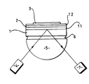
- Figure 1 is a schematic view of a sensor according to the invention.
- a biosensor for the determination of an antigen in a sample of body fluid comprises a glass slide (1) coated on one surface with a layer of silica (11) which in turn is coated with a thin layer of silver (2).
- the layer of silver (2) is coated with a thin layer of zirconia (12) upon which is immobilised a layer (3) of antibodies to the antigen under test.
- Light from a laser light source (4) is coupled into the slide (1) by a hemi-cylindrical prism (5) and a layer of index matching fluid (6).
- Total internal reflection occurs at the glass-silica interface and the reflected beam is coupled out of the slide (1) by the matching fluid (6) and prism (5).
- the intensity of the reflected light beam is measured by a detector (7).
- the silica layer (11) has a thickness of approximately 2000 nm, the silver layer (2) a thickness of approximately 23 nm and the zirconia layer (12) a thickness of approximately 18 nm.
- the angle of incidence of light from the light source (4) at which long range surface plasmon resonance occurs is detected by varying the angle of incidence. At resonance a sharp dip is observed in the intensity of light internally reflected at the interface between the glass slide (1) and the silica layer (11).
- a specific binding reaction occurs which changes the refractive index in the vicinity of the surface of the device. The results in a shift in the angular position of resonance which may be qualitatively and/or quantitatively related to the presence of analyte in the sample.
Abstract
Description
- This invention relates to sensors for the detection of chemical species, in particular to sensors for the detection of analytes in solution by the technique of long range surface plasmon resonance (SPR).
- SPR is well known for the detection of chemical species. SPR may be achieved by using the evanescent wave which is generated when a polarized light beam is totally internally reflected at the interface between a dielectric medium, eg glass, and a thin layer of metal. The technique is described by Lieberg et al in Sensors and Actuators, 4, 299. The basis for the application of SPR to sensing is the fact that the oscillation of the surface plasma of free electrons which exists at a metal-dielectric boundary is affected by the refractive index of the material adjacent to the metal surface. Resonance occurs when the angle of incidence of the radiation has a particular value, and this value is dependent on the refractive index of the material adjacent to the metal. Thus, changes in this refractive index give rise to changes in the angle at which resonance occurs. Resonance may be detected as a dip in the intensity of the internally reflected beam.
- In a typical SPR device, the thin layer of metal is coated on the surface of a glass prism. Recently, European Patent Application number 0346016 (Amersham) has suggested that the sensitivity of an SPR device may be enhanced by using the phenomenon of long range SPR. Long range SPR is described by Quail et al in Optics Letters, 8, 377 and involves a thin metal layer isolated from a coupling prism by a low refractive index "spacer" layer. This extra layer allows excitation of an SPR resonance on both metal dielectric interfaces, top and bottom, as opposed to the single resonance seen when just a metal layer is used. If the metal layer is thin enough, the field profiles from the two resonances will overlap, and they will have the opportunity to interact, provided that certain conditions are met. In particular, the propagation constants k of the two resonances must match, or at least be close to matching. Interaction will produce an anti-symmetric and a symmetric combination of the fields, labelled long range and short range SPR respectively. The anti-symmetric combination has a greater proportion of its field outside of the metal layer, and so suffers less loss, travels further along the surface (hence the name), and has a narrower resonance. The symmetric combination travels a shorter distance along the surface, and has a broader resonance.
- The condition for matching propagation constants has conventionally required the presence of dielectrics of the same refractive index at the two interfaces. This is a problem in sensors, eg biosensors, in which the sample under test is aqueous (blood plasma, for instance) and has a refractive index of approximately 1.33. Spacer materials having refractive indices close to this value are not common, and those which are available cannot readily be coated with a thin layer of metal. Magnesium fluoride has a refractive index of about 1.38, which is close enough to show coupling, but is some way from optimal.
- We have now devised a long range SPR device in which the above mentioned problem is overcome or substantially mitigated.
- According to the invention, there is provided a long range SPR sensor comprising:
- (a) a source of electromagnetic radiation,
- (b) an optical structure comprising a block of material transparent to said electromagnetic radiation, a spacer layer of dielectric material, a metallic layer and a sensitive layer capable of reaction with a sample to be tested, and
- (c) means for monitoring radiation from the source which is incident upon the block and which is internally reflected at the interface between the block and the spacer layer,
- The sensor according to the invention is advantageous in that the presence of the high refractive index dielectric between the metal layer and the sample under test results in a closer matching of the SPR propagation constants at the two metal surfaces. This enables the advantages of long range SPR to be more fully realised, notably a very sharp resonance with corresponding improvements in sensitivity. Further, these advantages may be realised while using readily available and otherwise suitable materials for the spacer layer, eg silica.
- The refractive index of the high refractive index dielectric layer should be sufficiently high to raise the effective index of the combination of sample and high refractive index layer to that of the spacer layer. The effective refractive index may also be increased by increasing the thickness of the extra layer and, in general, for best results it is necessary to optimise the thicknesses of all three layers. However, the high refractive index dielectric layer must be thin enough for the evanescent field to penetrate substantially into the sample, in order to provide sensitivity to changes occurring in the sensitive layer.
- The nature of the transparent block, the source of electromagnetic radiation and the detector will be apparent to those familiar with conventional SPR devices. By way of example, attention may be drawn to European Patent Application No 0305109 (Amersham) which describes such a device as well as to European Patent Application No 0346016 referred to above. In summary:
- the block is conveniently of glass, eg in the form of a glass chip or prism,
- the metallic coating is most conveniently of silver,
- the light source is any source which has a small spectral width and good coherence, eg a laser,
- the means for monitoring reflected radiation may be any of those conventionally employed, eg photo multipliers and charge-coupled devices.
- The sensitive layer will generally be sensitised by the inclusion of specific binding partners for the analyte under test, suitable such binding partners and methods for their immobilisation upon the high refractive index dielectric layer being apparent to those skilled in the art.
- The resonant condition may be detected by varying the angle of incidence of the radiation from the source, either by varying the angle of incidence sequentially or by simultaneously irradiating at a range of wavelengths.
- EP-A-0353937 describes SPR sensors, one having the layer structure: glass substrate-metal layer-dielectric layer-sensor layer, and one having the layer structure: glass substrate- dielectric layer-metal layer-sensor layer.
- An embodiment of the present invention will now be described by way of illustration only, with reference to the accompanying drawing in which:
- Figure 1 is a schematic view of a sensor according to the invention.
- A biosensor for the determination of an antigen in a sample of body fluid comprises a glass slide (1) coated on one surface with a layer of silica (11) which in turn is coated with a thin layer of silver (2). The layer of silver (2) is coated with a thin layer of zirconia (12) upon which is immobilised a layer (3) of antibodies to the antigen under test. Light from a laser light source (4) is coupled into the slide (1) by a hemi-cylindrical prism (5) and a layer of index matching fluid (6).
- Total internal reflection occurs at the glass-silica interface and the reflected beam is coupled out of the slide (1) by the matching fluid (6) and prism (5). The intensity of the reflected light beam is measured by a detector (7).
- The silica layer (11) has a thickness of approximately 2000 nm, the silver layer (2) a thickness of approximately 23 nm and the zirconia layer (12) a thickness of approximately 18 nm.
- The angle of incidence of light from the light source (4) at which long range surface plasmon resonance occurs is detected by varying the angle of incidence. At resonance a sharp dip is observed in the intensity of light internally reflected at the interface between the glass slide (1) and the silica layer (11). When a sample containing the analyte under test is brought into contact with the layer of immobilised antibodies (3) a specific binding reaction occurs which changes the refractive index in the vicinity of the surface of the device. The results in a shift in the angular position of resonance which may be qualitatively and/or quantitatively related to the presence of analyte in the sample.
Claims (9)
- A long range SPR sensor comprising:(a) a source of electromagnetic radiation (4),(b) an optical structure comprising a block (1) of material transparent to said electromagnetic radiation, a spacer layer (11) of dielectric material, a metallic layer (2) and a sensitive layer (3) capable of reaction with a sample to be tested, and(c) means (7) for monitoring radiation from the source (4) which is incident upon the block (1) and which is internally reflected at the interface between the block (1) and the spacer layer (11),characterised in that a thin layer of dielectric material (12) of high refractive index is interposed between the metallic layer (2) and the layer of sensitive material (3).
- A sensor as claimed in Claim 1, wherein the thin layer of dielectric material (12) is of zirconia.
- A sensor as claimed in Claim 1 or Claim 2, wherein the spacer layer (2) is of silica.
- A sensor as claimed in any one of the preceding claims, wherein the block (1) is of glass.
- A sensor as claimed in any one of the preceding claims, wherein the metallic coating (2) is of silver.
- A sensor as claimed in any one of the preceding claims, wherein the light source (4) is a laser.
- A sensor as claimed in any one of the preceding claims, wherein the means (7) for monitoring reflected radiation is a photo multiplier or a charge-coupled device.
- A sensor as claimed in any one of the preceding claims, wherein the sensitive layer (3) is sensitised by the inclusion of specific binding partners for the analyte under test.
- A sensor as claimed in any one of the preceding claims, wherein the resonant condition is detected by varying the angle of incidence of the radiation from the source (4), either by varying the angle of incidence sequentially or by simultaneously irradiating at a range of wavelengths.
Applications Claiming Priority (3)
| Application Number | Priority Date | Filing Date | Title |
|---|---|---|---|
| GB91026468 | 1991-02-07 | ||
| GB919102646A GB9102646D0 (en) | 1991-02-07 | 1991-02-07 | Analytical device |
| PCT/GB1992/000192 WO1992014140A1 (en) | 1991-02-07 | 1992-02-03 | Analytical device |
Publications (2)
| Publication Number | Publication Date |
|---|---|
| EP0570445A1 EP0570445A1 (en) | 1993-11-24 |
| EP0570445B1 true EP0570445B1 (en) | 1996-08-14 |
Family
ID=10689696
Family Applications (1)
| Application Number | Title | Priority Date | Filing Date |
|---|---|---|---|
| EP92904190A Expired - Lifetime EP0570445B1 (en) | 1991-02-07 | 1992-02-03 | Analytical device |
Country Status (6)
| Country | Link |
|---|---|
| US (1) | US5415842A (en) |
| EP (1) | EP0570445B1 (en) |
| JP (1) | JPH06506298A (en) |
| DE (1) | DE69212812D1 (en) |
| GB (1) | GB9102646D0 (en) |
| WO (1) | WO1992014140A1 (en) |
Families Citing this family (68)
| Publication number | Priority date | Publication date | Assignee | Title |
|---|---|---|---|---|
| DE4244086C2 (en) * | 1992-12-24 | 1994-10-27 | Florin Ernst Ludwig | Method and device for the detection of surface plasmons |
| US5898830A (en) * | 1996-10-17 | 1999-04-27 | Network Engineering Software | Firewall providing enhanced network security and user transparency |
| EP0797091A1 (en) * | 1996-03-19 | 1997-09-24 | Texas Instruments Incorporated | Surface plasmon resonance sensor with interchangable optical element |
| US5852229A (en) * | 1996-05-29 | 1998-12-22 | Kimberly-Clark Worldwide, Inc. | Piezoelectric resonator chemical sensing device |
| US6020047A (en) * | 1996-09-04 | 2000-02-01 | Kimberly-Clark Worldwide, Inc. | Polymer films having a printed self-assembling monolayer |
| US5846843A (en) * | 1996-11-18 | 1998-12-08 | The University Of Toledo | Sensor using long range surface plasmon resonance with diffraction double-grating |
| US6048623A (en) * | 1996-12-18 | 2000-04-11 | Kimberly-Clark Worldwide, Inc. | Method of contact printing on gold coated films |
| US5922550A (en) * | 1996-12-18 | 1999-07-13 | Kimberly-Clark Worldwide, Inc. | Biosensing devices which produce diffraction images |
| US5898503A (en) * | 1997-03-19 | 1999-04-27 | Texas Instruments Incorporated | Surface plasmon resonance sensor with interchangeable optical element |
| US6180288B1 (en) | 1997-03-21 | 2001-01-30 | Kimberly-Clark Worldwide, Inc. | Gel sensors and method of use thereof |
| US6060256A (en) * | 1997-12-16 | 2000-05-09 | Kimberly-Clark Worldwide, Inc. | Optical diffraction biosensor |
| DE19805809C2 (en) * | 1998-02-12 | 2000-02-17 | Biotul Bio Instr Gmbh | Determination of the surface plasmon resonance using locally or temporally modified layers |
| US6161437A (en) * | 1998-04-09 | 2000-12-19 | Georgia Tech Research Corporation | Method and apparatus for evaluating an analyte |
| US7640083B2 (en) * | 2002-11-22 | 2009-12-29 | Monroe David A | Record and playback system for aircraft |
| CN1237338C (en) | 1998-11-13 | 2006-01-18 | 莱卡微系统公司 | Refractometer and method for qualitative and quantitive measurements |
| US6221579B1 (en) | 1998-12-11 | 2001-04-24 | Kimberly-Clark Worldwide, Inc. | Patterned binding of functionalized microspheres for optical diffraction-based biosensors |
| US6579673B2 (en) | 1998-12-17 | 2003-06-17 | Kimberly-Clark Worldwide, Inc. | Patterned deposition of antibody binding protein for optical diffraction-based biosensors |
| US6771376B2 (en) * | 1999-07-05 | 2004-08-03 | Novartis Ag | Sensor platform, apparatus incorporating the platform, and process using the platform |
| PT1192448E (en) | 1999-07-05 | 2007-01-31 | Novartis Ag | Process of using a sensor platform |
| IL131903A0 (en) * | 1999-09-15 | 2001-03-19 | Technion Res & Dev Foundation | Plasmon resonance phase imaging |
| US7167615B1 (en) | 1999-11-05 | 2007-01-23 | Board Of Regents, The University Of Texas System | Resonant waveguide-grating filters and sensors and methods for making and using same |
| US6399295B1 (en) | 1999-12-17 | 2002-06-04 | Kimberly-Clark Worldwide, Inc. | Use of wicking agent to eliminate wash steps for optical diffraction-based biosensors |
| US6798521B2 (en) * | 2000-12-29 | 2004-09-28 | Texas Instruments Incorporated | Robust integrated surface plasmon resonance sensor |
| DE10145719A1 (en) * | 2001-09-17 | 2003-04-10 | Inst Chemo Biosensorik | Optical hydrogen sensor comprises an optically transparent substrate with a first surface, and a hydrogen-sensitive layer containing or consisting of a metal, metal oxide or polymer |
| US7102752B2 (en) | 2001-12-11 | 2006-09-05 | Kimberly-Clark Worldwide, Inc. | Systems to view and analyze the results from diffraction-based diagnostics |
| KR20030047567A (en) * | 2001-12-11 | 2003-06-18 | 한국전자통신연구원 | Surface plasmon resonance sensor system |
| US7098041B2 (en) | 2001-12-11 | 2006-08-29 | Kimberly-Clark Worldwide, Inc. | Methods to view and analyze the results from diffraction-based diagnostics |
| US20030119203A1 (en) * | 2001-12-24 | 2003-06-26 | Kimberly-Clark Worldwide, Inc. | Lateral flow assay devices and methods for conducting assays |
| US8367013B2 (en) * | 2001-12-24 | 2013-02-05 | Kimberly-Clark Worldwide, Inc. | Reading device, method, and system for conducting lateral flow assays |
| US7118855B2 (en) * | 2002-05-03 | 2006-10-10 | Kimberly-Clark Worldwide, Inc. | Diffraction-based diagnostic devices |
| US7214530B2 (en) * | 2002-05-03 | 2007-05-08 | Kimberly-Clark Worldwide, Inc. | Biomolecule diagnostic devices and method for producing biomolecule diagnostic devices |
| US7771922B2 (en) * | 2002-05-03 | 2010-08-10 | Kimberly-Clark Worldwide, Inc. | Biomolecule diagnostic device |
| US7223534B2 (en) * | 2002-05-03 | 2007-05-29 | Kimberly-Clark Worldwide, Inc. | Diffraction-based diagnostic devices |
| US7485453B2 (en) * | 2002-05-03 | 2009-02-03 | Kimberly-Clark Worldwide, Inc. | Diffraction-based diagnostic devices |
| US7223368B2 (en) * | 2002-05-03 | 2007-05-29 | Kimberly-Clark Worldwide, Inc. | Diffraction-based diagnostic devices |
| US7091049B2 (en) * | 2002-06-26 | 2006-08-15 | Kimberly-Clark Worldwide, Inc. | Enhanced diffraction-based biosensor devices |
| US7285424B2 (en) * | 2002-08-27 | 2007-10-23 | Kimberly-Clark Worldwide, Inc. | Membrane-based assay devices |
| US7314763B2 (en) * | 2002-08-27 | 2008-01-01 | Kimberly-Clark Worldwide, Inc. | Fluidics-based assay devices |
| US7169550B2 (en) * | 2002-09-26 | 2007-01-30 | Kimberly-Clark Worldwide, Inc. | Diffraction-based diagnostic devices |
| US20040106190A1 (en) * | 2002-12-03 | 2004-06-03 | Kimberly-Clark Worldwide, Inc. | Flow-through assay devices |
| US20040121334A1 (en) * | 2002-12-19 | 2004-06-24 | Kimberly-Clark Worldwide, Inc. | Self-calibrated flow-through assay devices |
| US7247500B2 (en) | 2002-12-19 | 2007-07-24 | Kimberly-Clark Worldwide, Inc. | Reduction of the hook effect in membrane-based assay devices |
| US20040197819A1 (en) * | 2003-04-03 | 2004-10-07 | Kimberly-Clark Worldwide, Inc. | Assay devices that utilize hollow particles |
| US7851209B2 (en) * | 2003-04-03 | 2010-12-14 | Kimberly-Clark Worldwide, Inc. | Reduction of the hook effect in assay devices |
| WO2005050181A1 (en) * | 2003-11-19 | 2005-06-02 | Beanor Oy | Method and device for carrying out surface plasmon resonance measurement |
| US7943395B2 (en) * | 2003-11-21 | 2011-05-17 | Kimberly-Clark Worldwide, Inc. | Extension of the dynamic detection range of assay devices |
| US7713748B2 (en) * | 2003-11-21 | 2010-05-11 | Kimberly-Clark Worldwide, Inc. | Method of reducing the sensitivity of assay devices |
| US20050112703A1 (en) * | 2003-11-21 | 2005-05-26 | Kimberly-Clark Worldwide, Inc. | Membrane-based lateral flow assay devices that utilize phosphorescent detection |
| WO2005052557A1 (en) * | 2003-11-28 | 2005-06-09 | Lumiscence A/S | An examination system for examination of a specimen; sub-units and units therefore, a sensor and a microscope |
| US20050136550A1 (en) * | 2003-12-19 | 2005-06-23 | Kimberly-Clark Worldwide, Inc. | Flow control of electrochemical-based assay devices |
| US7943089B2 (en) * | 2003-12-19 | 2011-05-17 | Kimberly-Clark Worldwide, Inc. | Laminated assay devices |
| US7521226B2 (en) * | 2004-06-30 | 2009-04-21 | Kimberly-Clark Worldwide, Inc. | One-step enzymatic and amine detection technique |
| CN101228446B (en) | 2005-07-20 | 2014-08-06 | 康宁股份有限公司 | Label-free high throughput biomolecular screening system and method |
| US7713689B2 (en) | 2005-09-15 | 2010-05-11 | Duke University | Non-fouling polymeric surface modification and signal amplification method for biomolecular detection |
| US7218802B1 (en) | 2005-11-30 | 2007-05-15 | Corning Incorporated | Low drift planar waveguide grating sensor and method for manufacturing same |
| WO2007072986A1 (en) * | 2005-12-22 | 2007-06-28 | Canon Kabushiki Kaisha | Substrate for target substance detecting device, target substance detecting device, target substance detecting apparatus and method using the same, and kit therefor |
| US7976217B2 (en) | 2006-09-15 | 2011-07-12 | Corning Incorporated | Screening system and method for analyzing a plurality of biosensors |
| US8796184B2 (en) | 2008-03-28 | 2014-08-05 | Sentilus, Inc. | Detection assay devices and methods of making and using the same |
| WO2010035232A1 (en) * | 2008-09-24 | 2010-04-01 | Koninklijke Philips Electronics N.V. | Assembly with absorbing sensor layer |
| KR100927378B1 (en) | 2008-11-13 | 2009-11-19 | 지에스건설 주식회사 | Gas sensor chip with thick sensing layer, and manufacturing method thereof |
| WO2011002117A1 (en) * | 2009-07-01 | 2011-01-06 | 한국과학기술연구원 | High sensitivity localized surface plasmon resonance sensor and sensor system using same |
| EP2571421B1 (en) | 2010-05-17 | 2017-08-02 | Sentilus Holdco, LLC | Detection devices and related methods of use |
| CN102183507B (en) * | 2011-03-01 | 2012-11-21 | 吉林大学 | Method for exciting surface-enhanced Raman spectroscopy (SERS) through long range surface plasmon |
| CN102809557B (en) * | 2012-01-18 | 2015-01-28 | 北京联合大学生物化学工程学院 | Nanometer sensitive material for detecting hydrogen sulfide |
| TWI512867B (en) * | 2012-12-14 | 2015-12-11 | Yayatech Co Ltd | Inspection method and inspection fixture for scribing lines of wafer |
| CN104792731B (en) * | 2014-12-17 | 2017-08-08 | 太原理工大学 | A kind of liquid refractive index sensor based on resonance light tunneling effect |
| CN104502279A (en) * | 2014-12-19 | 2015-04-08 | 中国计量学院 | Long-range surface plasma resonance device based on tilted fiber bragg grating |
| EP3325966B1 (en) | 2015-07-20 | 2021-01-20 | Sentilus Holdco, LLC | Chips, detectors, and methods of making and using the same |
Family Cites Families (5)
| Publication number | Priority date | Publication date | Assignee | Title |
|---|---|---|---|---|
| NL8700851A (en) * | 1987-04-10 | 1988-11-01 | Tno | METHOD AND APPARATUS FOR DETECTING VERY LOW CONCENTRATIONS OF A MEASURING MEDIA CHEMICAL COMPONENT USING SURFACE-PLASMON RESONANCE AND ELECTROCHEMICALLY STIMULATED ADSORPTION |
| CA1321488C (en) * | 1987-08-22 | 1993-08-24 | Martin Francis Finlan | Biological sensors |
| GB8813307D0 (en) * | 1988-06-06 | 1988-07-13 | Amersham Int Plc | Biological sensors |
| GB8817710D0 (en) * | 1988-07-25 | 1988-09-01 | Ares Serono Res & Dev Ltd | Method of assay |
| GB2248497B (en) * | 1990-09-26 | 1994-05-25 | Marconi Gec Ltd | An optical sensor |
-
1991
- 1991-02-07 GB GB919102646A patent/GB9102646D0/en active Pending
-
1992
- 1992-02-03 JP JP4504023A patent/JPH06506298A/en active Pending
- 1992-02-03 US US08/094,032 patent/US5415842A/en not_active Expired - Fee Related
- 1992-02-03 DE DE69212812T patent/DE69212812D1/en not_active Expired - Lifetime
- 1992-02-03 WO PCT/GB1992/000192 patent/WO1992014140A1/en active IP Right Grant
- 1992-02-03 EP EP92904190A patent/EP0570445B1/en not_active Expired - Lifetime
Also Published As
| Publication number | Publication date |
|---|---|
| DE69212812D1 (en) | 1996-09-19 |
| EP0570445A1 (en) | 1993-11-24 |
| US5415842A (en) | 1995-05-16 |
| GB9102646D0 (en) | 1991-03-27 |
| JPH06506298A (en) | 1994-07-14 |
| WO1992014140A1 (en) | 1992-08-20 |
Similar Documents
| Publication | Publication Date | Title |
|---|---|---|
| EP0570445B1 (en) | Analytical device | |
| US6320991B1 (en) | Optical sensor having dielectric film stack | |
| EP0546061B1 (en) | Surface plasmon resonance device | |
| EP0543831B1 (en) | Analytical device | |
| EP0205236B1 (en) | Improvements in or relating to optic-waveguide biosensors | |
| US5210404A (en) | Optical sensor including a bragg grating structure for enhanced sensitivity | |
| Jorgenson et al. | Control of the dynamic range and sensitivity of a surface plasmon resonance based fiber optic sensor | |
| US5081012A (en) | Waveguide sensor with input and reflecting gratings and its use in immunoassay | |
| EP0346016B1 (en) | Biological sensors | |
| US5478755A (en) | Long range surface plasma resonance immunoassay | |
| US5071248A (en) | Optical sensor for selective detection of substances and/or for the detection of refractive index changes in gaseous, liquid, solid and porous samples | |
| US5606633A (en) | Chemical detector employing surface plasmon resonance excited using an optical waveguide configured as an asymmetric waveguide coupler | |
| USRE37473E1 (en) | Diffraction anomaly sensor having grating coated with protective dielectric layer | |
| US5491556A (en) | Analytical device with variable angle of incidence | |
| US20030099422A1 (en) | Active ion-doped waveguide-plasmon resonance sensor based on upconversion of active ions and imaging system using the same | |
| GB2197065A (en) | Optical sensor device | |
| EP0382832B1 (en) | Method of assay fora ligand in a sample | |
| WO1993014392A1 (en) | Analytical device with polychromatic light source | |
| EP0620916A1 (en) | Analytical device with light scattering | |
| US20190056389A1 (en) | System and method for determining the presence or absence of adsorbed biomolecules or biomolecular structures on a surface | |
| WO1994025850A1 (en) | Analytical device | |
| Homola et al. | Fiber optic sensor for adsorption studies using surface plasmon resonance | |
| EP4103929B1 (en) | Method of analysis of refractive index using a polarisation-sensitive optical sensor and sensor system comprising the optical sensor | |
| CN117629946A (en) | Optical sensor based on photonic crystal coupling structure and optical detection method | |
| Homola et al. | Surface plasmon resonance sensors using optical waveguides |
Legal Events
| Date | Code | Title | Description |
|---|---|---|---|
| PUAI | Public reference made under article 153(3) epc to a published international application that has entered the european phase |
Free format text: ORIGINAL CODE: 0009012 |
|
| 17P | Request for examination filed |
Effective date: 19930709 |
|
| AK | Designated contracting states |
Kind code of ref document: A1 Designated state(s): BE CH DE FR GB IT LI NL SE |
|
| 17Q | First examination report despatched |
Effective date: 19951016 |
|
| GRAH | Despatch of communication of intention to grant a patent |
Free format text: ORIGINAL CODE: EPIDOS IGRA |
|
| GRAH | Despatch of communication of intention to grant a patent |
Free format text: ORIGINAL CODE: EPIDOS IGRA |
|
| GRAA | (expected) grant |
Free format text: ORIGINAL CODE: 0009210 |
|
| AK | Designated contracting states |
Kind code of ref document: B1 Designated state(s): BE CH DE FR GB IT LI NL SE |
|
| PG25 | Lapsed in a contracting state [announced via postgrant information from national office to epo] |
Ref country code: NL Free format text: LAPSE BECAUSE OF FAILURE TO SUBMIT A TRANSLATION OF THE DESCRIPTION OR TO PAY THE FEE WITHIN THE PRESCRIBED TIME-LIMIT Effective date: 19960814 Ref country code: LI Effective date: 19960814 Ref country code: IT Free format text: LAPSE BECAUSE OF FAILURE TO SUBMIT A TRANSLATION OF THE DESCRIPTION OR TO PAY THE FEE WITHIN THE PRE;WARNING: LAPSES OF ITALIAN PATENTS WITH EFFECTIVE DATE BEFORE 2007 MAY HAVE OCCURRED AT ANY TIME BEFORE 2007. THE CORRECT EFFECTIVE DATE MAY BE DIFFERENT FROM THE ONE RECORDED.SCRIBED TIME-LIMIT Effective date: 19960814 Ref country code: FR Effective date: 19960814 Ref country code: CH Effective date: 19960814 Ref country code: BE Effective date: 19960814 |
|
| REF | Corresponds to: |
Ref document number: 69212812 Country of ref document: DE Date of ref document: 19960919 |
|
| PG25 | Lapsed in a contracting state [announced via postgrant information from national office to epo] |
Ref country code: SE Effective date: 19961114 |
|
| PG25 | Lapsed in a contracting state [announced via postgrant information from national office to epo] |
Ref country code: DE Effective date: 19961115 |
|
| EN | Fr: translation not filed | ||
| NLV1 | Nl: lapsed or annulled due to failure to fulfill the requirements of art. 29p and 29m of the patents act | ||
| PG25 | Lapsed in a contracting state [announced via postgrant information from national office to epo] |
Ref country code: GB Effective date: 19970203 |
|
| REG | Reference to a national code |
Ref country code: CH Ref legal event code: PL |
|
| RAP2 | Party data changed (patent owner data changed or rights of a patent transferred) |
Owner name: FISONS PLC |
|
| PLBE | No opposition filed within time limit |
Free format text: ORIGINAL CODE: 0009261 |
|
| STAA | Information on the status of an ep patent application or granted ep patent |
Free format text: STATUS: NO OPPOSITION FILED WITHIN TIME LIMIT |
|
| 26N | No opposition filed | ||
| GBPC | Gb: european patent ceased through non-payment of renewal fee |
Effective date: 19970203 |