EP0567080A1 - Optical information storage disk for use with electronic article surveillance systems - Google Patents
Optical information storage disk for use with electronic article surveillance systems Download PDFInfo
- Publication number
- EP0567080A1 EP0567080A1 EP93106403A EP93106403A EP0567080A1 EP 0567080 A1 EP0567080 A1 EP 0567080A1 EP 93106403 A EP93106403 A EP 93106403A EP 93106403 A EP93106403 A EP 93106403A EP 0567080 A1 EP0567080 A1 EP 0567080A1
- Authority
- EP
- European Patent Office
- Prior art keywords
- marker
- disk
- generally
- magnetic
- annulus
- Prior art date
- Legal status (The legal status is an assumption and is not a legal conclusion. Google has not performed a legal analysis and makes no representation as to the accuracy of the status listed.)
- Granted
Links
- 230000003287 optical effect Effects 0.000 title claims abstract description 10
- 239000003550 marker Substances 0.000 claims abstract description 89
- 230000005291 magnetic effect Effects 0.000 claims abstract description 43
- 239000011248 coating agent Substances 0.000 claims abstract description 6
- 238000000576 coating method Methods 0.000 claims abstract description 6
- 239000000463 material Substances 0.000 claims description 15
- 230000004044 response Effects 0.000 claims description 14
- 230000004907 flux Effects 0.000 claims description 10
- 230000002093 peripheral effect Effects 0.000 claims description 8
- 230000035699 permeability Effects 0.000 claims description 8
- 238000007789 sealing Methods 0.000 claims description 5
- 150000001875 compounds Chemical class 0.000 claims description 3
- 239000004922 lacquer Substances 0.000 claims description 3
- 239000000853 adhesive Substances 0.000 claims description 2
- 230000001070 adhesive effect Effects 0.000 claims description 2
- 238000012544 monitoring process Methods 0.000 abstract description 4
- 230000009977 dual effect Effects 0.000 abstract description 3
- 230000000717 retained effect Effects 0.000 abstract description 3
- 238000004806 packaging method and process Methods 0.000 description 8
- 238000000034 method Methods 0.000 description 5
- 239000003302 ferromagnetic material Substances 0.000 description 4
- 238000001514 detection method Methods 0.000 description 3
- 239000000696 magnetic material Substances 0.000 description 2
- 230000004913 activation Effects 0.000 description 1
- 238000013500 data storage Methods 0.000 description 1
- 230000009849 deactivation Effects 0.000 description 1
- 239000003814 drug Substances 0.000 description 1
- 238000003780 insertion Methods 0.000 description 1
- 230000037431 insertion Effects 0.000 description 1
- 230000005415 magnetization Effects 0.000 description 1
- 239000000820 nonprescription drug Substances 0.000 description 1
- 239000010816 packaging waste Substances 0.000 description 1
- 229910000889 permalloy Inorganic materials 0.000 description 1
- 230000010287 polarization Effects 0.000 description 1
- 238000002360 preparation method Methods 0.000 description 1
- 239000000955 prescription drug Substances 0.000 description 1
- 230000008569 process Effects 0.000 description 1
- 230000005855 radiation Effects 0.000 description 1
- 229910001220 stainless steel Inorganic materials 0.000 description 1
- 239000010935 stainless steel Substances 0.000 description 1
- 238000005482 strain hardening Methods 0.000 description 1
- 229910000815 supermalloy Inorganic materials 0.000 description 1
- 229910000586 vicalloy Inorganic materials 0.000 description 1
- 125000000391 vinyl group Chemical group [H]C([*])=C([H])[H] 0.000 description 1
- 229920002554 vinyl polymer Polymers 0.000 description 1
Images
Classifications
-
- G—PHYSICS
- G11—INFORMATION STORAGE
- G11B—INFORMATION STORAGE BASED ON RELATIVE MOVEMENT BETWEEN RECORD CARRIER AND TRANSDUCER
- G11B7/00—Recording or reproducing by optical means, e.g. recording using a thermal beam of optical radiation by modifying optical properties or the physical structure, reproducing using an optical beam at lower power by sensing optical properties; Record carriers therefor
-
- G—PHYSICS
- G11—INFORMATION STORAGE
- G11B—INFORMATION STORAGE BASED ON RELATIVE MOVEMENT BETWEEN RECORD CARRIER AND TRANSDUCER
- G11B23/00—Record carriers not specific to the method of recording or reproducing; Accessories, e.g. containers, specially adapted for co-operation with the recording or reproducing apparatus ; Intermediate mediums; Apparatus or processes specially adapted for their manufacture
- G11B23/28—Indicating or preventing prior or unauthorised use, e.g. cassettes with sealing or locking means, write-protect devices for discs
- G11B23/286—Antitheft arrangements, e.g. Electronic Article Surveillance [EAS] tags
-
- G—PHYSICS
- G08—SIGNALLING
- G08B—SIGNALLING OR CALLING SYSTEMS; ORDER TELEGRAPHS; ALARM SYSTEMS
- G08B13/00—Burglar, theft or intruder alarms
- G08B13/22—Electrical actuation
- G08B13/24—Electrical actuation by interference with electromagnetic field distribution
- G08B13/2402—Electronic Article Surveillance [EAS], i.e. systems using tags for detecting removal of a tagged item from a secure area, e.g. tags for detecting shoplifting
- G08B13/2405—Electronic Article Surveillance [EAS], i.e. systems using tags for detecting removal of a tagged item from a secure area, e.g. tags for detecting shoplifting characterised by the tag technology used
- G08B13/2408—Electronic Article Surveillance [EAS], i.e. systems using tags for detecting removal of a tagged item from a secure area, e.g. tags for detecting shoplifting characterised by the tag technology used using ferromagnetic tags
-
- G—PHYSICS
- G08—SIGNALLING
- G08B—SIGNALLING OR CALLING SYSTEMS; ORDER TELEGRAPHS; ALARM SYSTEMS
- G08B13/00—Burglar, theft or intruder alarms
- G08B13/22—Electrical actuation
- G08B13/24—Electrical actuation by interference with electromagnetic field distribution
- G08B13/2402—Electronic Article Surveillance [EAS], i.e. systems using tags for detecting removal of a tagged item from a secure area, e.g. tags for detecting shoplifting
- G08B13/2428—Tag details
- G08B13/2434—Tag housing and attachment details
-
- G—PHYSICS
- G08—SIGNALLING
- G08B—SIGNALLING OR CALLING SYSTEMS; ORDER TELEGRAPHS; ALARM SYSTEMS
- G08B13/00—Burglar, theft or intruder alarms
- G08B13/22—Electrical actuation
- G08B13/24—Electrical actuation by interference with electromagnetic field distribution
- G08B13/2402—Electronic Article Surveillance [EAS], i.e. systems using tags for detecting removal of a tagged item from a secure area, e.g. tags for detecting shoplifting
- G08B13/2428—Tag details
- G08B13/2437—Tag layered structure, processes for making layered tags
- G08B13/2442—Tag materials and material properties thereof, e.g. magnetic material details
-
- G—PHYSICS
- G08—SIGNALLING
- G08B—SIGNALLING OR CALLING SYSTEMS; ORDER TELEGRAPHS; ALARM SYSTEMS
- G08B13/00—Burglar, theft or intruder alarms
- G08B13/22—Electrical actuation
- G08B13/24—Electrical actuation by interference with electromagnetic field distribution
- G08B13/2402—Electronic Article Surveillance [EAS], i.e. systems using tags for detecting removal of a tagged item from a secure area, e.g. tags for detecting shoplifting
- G08B13/2428—Tag details
- G08B13/2437—Tag layered structure, processes for making layered tags
- G08B13/2445—Tag integrated into item to be protected, e.g. source tagging
-
- G—PHYSICS
- G11—INFORMATION STORAGE
- G11B—INFORMATION STORAGE BASED ON RELATIVE MOVEMENT BETWEEN RECORD CARRIER AND TRANSDUCER
- G11B23/00—Record carriers not specific to the method of recording or reproducing; Accessories, e.g. containers, specially adapted for co-operation with the recording or reproducing apparatus ; Intermediate mediums; Apparatus or processes specially adapted for their manufacture
- G11B23/0014—Record carriers not specific to the method of recording or reproducing; Accessories, e.g. containers, specially adapted for co-operation with the recording or reproducing apparatus ; Intermediate mediums; Apparatus or processes specially adapted for their manufacture record carriers not specifically of filamentary or web form
- G11B23/0021—Record carriers not specific to the method of recording or reproducing; Accessories, e.g. containers, specially adapted for co-operation with the recording or reproducing apparatus ; Intermediate mediums; Apparatus or processes specially adapted for their manufacture record carriers not specifically of filamentary or web form discs
- G11B23/0028—Details
- G11B23/0035—Details means incorporated in the disc, e.g. hub, to enable its guiding, loading or driving
- G11B23/0042—Details means incorporated in the disc, e.g. hub, to enable its guiding, loading or driving with provision for auxiliary features
-
- G—PHYSICS
- G11—INFORMATION STORAGE
- G11B—INFORMATION STORAGE BASED ON RELATIVE MOVEMENT BETWEEN RECORD CARRIER AND TRANSDUCER
- G11B7/00—Recording or reproducing by optical means, e.g. recording using a thermal beam of optical radiation by modifying optical properties or the physical structure, reproducing using an optical beam at lower power by sensing optical properties; Record carriers therefor
- G11B7/24—Record carriers characterised by shape, structure or physical properties, or by the selection of the material
Definitions
- This invention relates in general to data storage disks for encoding data in optically detectable, generally concentric data tracks.
- it relates to compact optical information storage disks especially adapted for use with an electronic article surveillance (EAS) system.
- EAS electronic article surveillance
- the now familiar compact disk preserves information as a series of microscopic pits and smooth areas, oriented in concentric circular or helical tracks, on the otherwise smooth, planar surface of an annular disk.
- Recorded information is read from a compact disk by directing a focused laser beam along the recorded tracks, and detecting variations in the intensity of the laser beam as it encounters the microscopic pits and smooth areas on the disk.
- the coherence and relatively short wavelength of laser radiation enables large volumes of information to be written onto very small spaces of a recording medium.
- the recording industry has for the last ten years packaged the five inch in diameter prerecorded compact disks in six inch (15 cm) by twelve inch (30 cm) cardboard boxes known in the industry as "longboxes.”
- the longbox is easily propped up in display bins alongside traditional vinyl LPs in music store display bins. More importantly, however, the bulk of the longbox makes it difficult for a shoplifter to hide a prerecorded compact disk under a coat or in a purse and walk out of a music store without paying.
- Electronic article surveillance systems for monitoring the egress of sensitive objects from controlled spaces are well known, and have been used alone and along with the longbox packaging technique for controlling the unauthorized taking of compact disks.
- Markers formed from a piece of high permeability magnetic material can be placed on the packaging for the disk.
- Spaced apart detection panels are then placed across the access points to and from the store, library or other repository for the monitored compact disks.
- the panels include field coils and detector coils for producing a magnetic field across the access point that can detect the passage of a marker between the panels. If a person attempts to carry a compact disk through the magnetic field presented by the panels without first deactivating the marker on the disk packaging, the presence of the marker will be detected and an alarm initiated.
- U. S. Patent No. 4,710,754 discloses a multi-directional EAS marker especially designed for its compact dimensions.
- the marker disclosed in the '754 patent is comprised of a high permeability, low coercive force, generally planar magnetic responder material that includes at least two narrow regions defining switching sections, and adjacent, wider, flux collector sections. The juxtaposition of the narrow switching sections with the flux collector sections causes the flux to be highly concentrated in the switching sections. The high concentration of flux lines in the switching sections produces high frequency harmonics when passed through an alternating magnetic field, allowing the presence of the marker in the field to be detected.
- the marker is conveniently made dual status, i.e., reversibly deactivatable and reactivatable, by including a piece of remanently magnetizable material adjacent each of the switching sections.
- the remanently magnetizable material when magnetized, biases the adjacent switching section to either keep the magnetization therein from reversing when in an alternating interrogation field, or at least altering the response of the marker in the field. In either case, readily distinguishably different signals are produced by the marker in an interrogation field depending on whether the remanently magnetizable material is magnetized or demagnetized.
- U. S. Patent No. 4,967,185 discloses a multi-directional, dual-status EAS marker also designed for its compact dimensions.
- the marker disclosed in the '185 patent discloses a marker that includes a continuous uninterrupted sheet of remanently magnetizable material overlying a sheet of responder material similar to that disclosed in the '754 patent.
- the response of the marker within an alternating magnetic field can be discernably altered by selectively magnetizing and demagnetizing the continuous sheet of remanently magnetizable material prior to introducing the marker into the field.
- the markers disclosed in the above noted prior art can be attached to the packaging for a compact disk. Problems arise, however, when attempting to attach prior art markers directly to the surface of a compact disk. Rotation of the compact disk is required to read information from the disk, and the disk must accordingly be inherently balanced. An EAS marker, applied directly to a compact disk, therefor, would preferably be somehow concentrically mounted on the disk without imbalancing the disk. Prior art EAS markers, however, are not inherently balanced. Moreover, conventional compact disks include a centered aperture that must be maintained clear of obstructions, and the preferred prior art dual status EAS markers include a continuous sheet of magnetic material, such that the marker cannot be concentrically mounted to the surface of a compact disk without obstructing the disk aperture.
- U. S. Patent No. 4,709,813 proposed an anti-theft device for compact disks that overcame the inability to directly apply an EAS marker to the surface of a compact disk.
- the '813 patent discloses a detachable locking plate with an EAS marker carried on the internal face of the plate that can be selectively locked to the "jewelry box" for a compact disk.
- the compact disk is physically locked in the box leg by the plate.
- a clerk or other authorized person can remove the plate with the use of a keyed release tool at the time of payment.
- the compact, optical information storage disk in accordance with the present invention is especially adapted for tamper-proof monitoring by an electronic article surveillance system.
- the compact disk hereof includes a generally planar, annular first disk surface and an opposed, generally annular second disk surface oriented generally parallel to the first disk surface, a plurality of generally concentric data tracks on at least one of the disk surfaces, a centered aperture and a generally annular magnetic marker concentrically oriented about the centered aperture.
- the marker is preferably adhered to the bottom of a grooved recess presented by one of the disk surfaces, and is thereafter immovably retained in the recess by a coating covering the disk surface.
- the EAS marker hereof includes a first annular member formed from a high permeability, low coercive force ferromagnetic material having a plurality of magnetic switching areas into which flux collected from adjacent areas is concentrated, thereby enabling a characteristic, readily distinguishable response to be created upon reversal of the magnetic state within at least one switching area when the marker is placed within an alternating magnetic field forming an interrogation zone.
- the width of the first annular member is restricted at least two locations positioned approximately at ninety degrees with respect to each other about the annulus to present at least two narrow switching regions alternating with wider flux collecting regions.
- the generally orthogonal relative orientation of the switching sections provides for multi-directional detection of the EAS marker in the alternating magnetic interrogation field.
- the marker further includes a second annulus member overlying the first member, and formed from a relatively high coercive force ferromagnetic material which, when magnetized, for example, in a single, linear direction, notwithstanding the annular shape of the member, alters the characteristic response of the marker when in the interrogation zone from the response resulting when the second member is demagnetized, thereby providing for the selective activation and deactivation of the EAS marker.
- the optical information storage disks hereof are designed to be stored in an access controlled space, with entrance and egress to the space directed only through the magnetic field established by the panels of an electronic article surveillance system. Passage of a disk through the panels will initiate an alarm, unless either the marker or the magnetic field is deactivated.
- the magnetic markers of the security cartridges are desirably made essentially tamper proof by applying a sealing compound, such as a lacquer coating, over the marker on the surface of the disk. Other layers or sealing techniques may also be employed to prevent removal.
- an optical information storage disk 10 in accordance with the present invention broadly includes a generally planar, annular first disk surface 12, an opposed, annular second disk surface 14 oriented generally parallel to the first disk surface 12, and an annular magnetic marker 16 carried within an annular groove 18 in the first disk surface 12. Centered aperture 20 and circular peripheral rim 22 extend between the first surface 12 and second surface 14. The magnetic marker 16 is concentrically oriented about the centered aperture 20.
- Information tracks 24 are made up of microscopic pits and smooth areas on the disk first surface 12.
- the tracks 24 can be either circular or helical and are concentrically oriented about the centered aperture 20.
- the annular groove 18 presents a generally cylindrical groove inner wall 26, an opposed generally cylindrical groove outer wall 28, and a generally annular bottom wall 30 extending between the groove inner wall 26 and outer wall 28.
- the groove inner wall 26 and outer wall 28 are both oriented generally normal to the first disk surface 12.
- the groove bottom wall 30 is recessed from, and oriented generally parallel to, the first disk surface 12.
- Magnetic marker 16 includes a first annulus member 32 formed from a high permeability, low coercive force ferromagnetic material such as permalloy, supermalloy, or the like.
- the annulus member 32 has an upper surface 34, a lower surface 36, an inner peripheral rim 38, and an outer peripheral rim 40.
- the notches 42 are formed on the internal peripheral rim 38 of the annulus 32.
- the notches 42 are spaced apart at approximately ninety degree intervals along the rim 40.
- Four external notches 44 are formed in the outer peripheral rim 40 of the annulus member 32 in opposed relationship with the internal notches 42.
- the opposed pairs of notches 42, 44 define regions of reduced cross sectional area 46 along the annulus 32. Flux collection regions 47 are created between the areas 46.
- a second annulus member 48 is adhesively coupled to, and is substantially coextensive with, the first annulus member 32.
- the second annulus member 48 is formed from a sheet of relatively high coercive force ferromagnetic material such vicalloy, magnetic stainless steel, Chromendur II, or the like.
- the annulus member 48 includes an upper surface 50, an opposed, lower surface 52 adhesively bonded to the upper surface 34 of the first annulus member 32, an inner peripheral rim 54 generally co-extensive with the inner rim 38 of the first annulus member 38, and an outer rim 56 co-extensive with the outer rim 40 of the first annulus member 32.
- the inner rim 38 of the first annulus member 32 and the inner rim 54 of the second annulus member 48 present a marker inner rim 58.
- the groove inner diameter presented by groove inner wall 26 is matched to the inner diameter presented by marker rim 58 such that the marker 16 is self-centered about the centered aperture 20 of disk 10 by the engagement of the inner rim 58 of marker 16 with the groove inner wall 26, while avoiding force fitting the marker, which could place mechanical stress on the marker.
- the outer rim 40 of first annulus member 32 and outer rim 56 of annulus member 48 define a marker outer rim 60.
- the groove outer diameter presented by groove outer wall 28 is similarly matched to the outer diameter of marker 16 presented by marker outer rim 60 such that the marker 16 is also self-centered about the disk centered aperture 20 by engagement of the marker outer peripheral rim 60 with the groove outer wall 28.
- the magnetic marker 16 can be retained within the groove 18 by an adhesive bond applied between the lower surface 34 of annulus member 32 and the groove bottom wall 30.
- a coating 62 such as a lacquer finish, applied to and carried by the first disk surface 12 is received within the groove 18, and immovably positions the magnetic marker 16 within the groove 18.
- FIG. 4 An alternate embodiment of the marker 16' is depicted in Figure 4.
- the marker 16' is similar in many respects to the marker 16, and identical features between the two markers are annotated with identical numbers in the drawings, and similar but not identical features are indicated in Figure 4 with primed (') numbers.
- the switching sections of the marker 16' are not created by physically removing material from the first annulus member 32'. Rather, the "notches" 42', 44' are formed by physically striking the annulus 32' at the points where the "notches" 42, 44 are desired, or by otherwise work hardening the annulus 32' at the desired points. In this way, the permeability of the material at those points is lowered so that the material can no longer magnetically reverse rapidly enough to create a characteristic response.
- the marker 16 can be magnetically switched between a first state wherein it is responsive to a magnetic interrogation field to initiate an alarm as it is passed through the field, and a second state wherein it is unresponsive to the interrogation field.
- the marker 16 is switched between an active and deactive state by uniformly magnetizing and demagnetizing the second annulus member 48 of the marker 16. More particularly, the marker 16 is reliably switched from a first, active state into a second, deactivated state, by substantially uniformly magnetizing the magnetizable member 48 so as to exhibit a first magnetic polarity along one end of the member 48 and an opposite polarity at the opposite end of the member 48. This essentially linear polarization is opposed to the generally annular physical shape of the member 48. It will be appreciated that the marker 16, although of relatively small size, provides a readily distinguishable response because of the presence of flux collector regions 47 presented by the pairs of opposed notches 42, 44 of the first annulus member 32 of marker 16.
- the optical information storage disk 10 can be kept in an access controlled space, such as the display space of a retail store having entrance and egress to the space directed only through the magnetic field established by the panels of an electronic article surveillance system.
- the disks 10 would be stored with their magnetic markers 16 in the active state such that removal of a disk from the store, through the magnetic field, would set off an alarm.
- the clerk Upon proper check out of a disk 10 with a clerk, however, the clerk would deactivate the marker 16 such that its passage through the magnetic field would not initiate an alarm.
- the coating 62 effectively immovably seals the marker 16 within the groove 18 without hindering the readability of the data tracks 24 on the disk 10, since it would be difficult or impossible to remove the marker 16 without damaging the disk. Excess packaging techniques, such as use of the "longbox,” can accordingly be dispensed with, without undesirably increasing the chance of unauthorized removal of a disk from a controlled space.
- the marker 16 (and the alternative embodiment of the marker 16') disclosed herein has been especially adapted for use with compact disks, it will be appreciated that the unique shape and magnetic orientation of the marker 16 make it adaptable to other applications. For instance, the small size and annular shape of the marker 16 make it ideal for insertion into the cap of a container for pharmaceuticals, thereby providing for EAS monitoring of heretofore pilferable prescription and nonprescription drugs.
Abstract
Description
- This invention relates in general to data storage disks for encoding data in optically detectable, generally concentric data tracks. In particular, it relates to compact optical information storage disks especially adapted for use with an electronic article surveillance (EAS) system.
- The now familiar compact disk preserves information as a series of microscopic pits and smooth areas, oriented in concentric circular or helical tracks, on the otherwise smooth, planar surface of an annular disk. Recorded information is read from a compact disk by directing a focused laser beam along the recorded tracks, and detecting variations in the intensity of the laser beam as it encounters the microscopic pits and smooth areas on the disk. The coherence and relatively short wavelength of laser radiation enables large volumes of information to be written onto very small spaces of a recording medium.
- Compact disks were first introduced in the music recording industry in 1982, and now account for 43% of all recorded music sales. In the United States alone, over three hundred million compact disks are sold annually, with a retail value of over three billion dollars, according to the Recording Industry Association of America.
- The recording industry has for the last ten years packaged the five inch in diameter prerecorded compact disks in six inch (15 cm) by twelve inch (30 cm) cardboard boxes known in the industry as "longboxes." The longbox is easily propped up in display bins alongside traditional vinyl LPs in music store display bins. More importantly, however, the bulk of the longbox makes it difficult for a shoplifter to hide a prerecorded compact disk under a coat or in a purse and walk out of a music store without paying.
- While the longbox packaging technique for prerecorded compact disks has been somewhat effective as an anti-theft device, the excess packaging it creates accounts for as much as twenty five million pounds of packaging waste annually. The Recording Industry Association of America accordingly announced in 1991 its intention to abandon the longbox. In February of 1992, the Association announced that, beginning in April 1993, all prerecorded compact disks would be marketed in five inch (12.7 cm) by five and one half inch (14 cm) packages.
- Electronic article surveillance systems for monitoring the egress of sensitive objects from controlled spaces are well known, and have been used alone and along with the longbox packaging technique for controlling the unauthorized taking of compact disks. Markers formed from a piece of high permeability magnetic material can be placed on the packaging for the disk. Spaced apart detection panels are then placed across the access points to and from the store, library or other repository for the monitored compact disks. The panels include field coils and detector coils for producing a magnetic field across the access point that can detect the passage of a marker between the panels. If a person attempts to carry a compact disk through the magnetic field presented by the panels without first deactivating the marker on the disk packaging, the presence of the marker will be detected and an alarm initiated.
- U. S. Patent No. 4,710,754 discloses a multi-directional EAS marker especially designed for its compact dimensions. The marker disclosed in the '754 patent is comprised of a high permeability, low coercive force, generally planar magnetic responder material that includes at least two narrow regions defining switching sections, and adjacent, wider, flux collector sections. The juxtaposition of the narrow switching sections with the flux collector sections causes the flux to be highly concentrated in the switching sections. The high concentration of flux lines in the switching sections produces high frequency harmonics when passed through an alternating magnetic field, allowing the presence of the marker in the field to be detected. The marker is conveniently made dual status, i.e., reversibly deactivatable and reactivatable, by including a piece of remanently magnetizable material adjacent each of the switching sections. The remanently magnetizable material, when magnetized, biases the adjacent switching section to either keep the magnetization therein from reversing when in an alternating interrogation field, or at least altering the response of the marker in the field. In either case, readily distinguishably different signals are produced by the marker in an interrogation field depending on whether the remanently magnetizable material is magnetized or demagnetized.
- U. S. Patent No. 4,967,185 discloses a multi-directional, dual-status EAS marker also designed for its compact dimensions. The marker disclosed in the '185 patent discloses a marker that includes a continuous uninterrupted sheet of remanently magnetizable material overlying a sheet of responder material similar to that disclosed in the '754 patent. The response of the marker within an alternating magnetic field can be discernably altered by selectively magnetizing and demagnetizing the continuous sheet of remanently magnetizable material prior to introducing the marker into the field.
- The markers disclosed in the above noted prior art can be attached to the packaging for a compact disk. Problems arise, however, when attempting to attach prior art markers directly to the surface of a compact disk. Rotation of the compact disk is required to read information from the disk, and the disk must accordingly be inherently balanced. An EAS marker, applied directly to a compact disk, therefor, would preferably be somehow concentrically mounted on the disk without imbalancing the disk. Prior art EAS markers, however, are not inherently balanced. Moreover, conventional compact disks include a centered aperture that must be maintained clear of obstructions, and the preferred prior art dual status EAS markers include a continuous sheet of magnetic material, such that the marker cannot be concentrically mounted to the surface of a compact disk without obstructing the disk aperture.
- U. S. Patent No. 4,709,813 proposed an anti-theft device for compact disks that overcame the inability to directly apply an EAS marker to the surface of a compact disk. The '813 patent discloses a detachable locking plate with an EAS marker carried on the internal face of the plate that can be selectively locked to the "jewelry box" for a compact disk. The compact disk is physically locked in the box leg by the plate. A clerk or other authorized person can remove the plate with the use of a keyed release tool at the time of payment. It will be appreciated that the use of a locking plate requires preparation time to attach a plate to each compact disk cartridge, adds an additional step in the check-out process, and leaves the compact disk without EAS protection once the EAS marker carrying plate is removed from the compact disk. The lack of EAS protection once the plate is removed makes it especially risky for a retailer to permit the trial playing of a compact disk by a customer in the store before the compact disk is purchased.
- The new packaging standard for prerecorded compact disks, while environmentally sound, will exacerbate the problem of compact disk shoplifting, since the smaller packages will be easier to hide and transport out of a store. While the use of electronic article surveillance systems could partially compensate for the increased shoplifting threat, it will be appreciated that the unauthorized removal of the magnetic markers from a package will defeat the detection capability of the surveillance system, and known EAS markers cannot be directly mounted on a compact disk without affecting the operability of the disk. The use of an EAS marker in conjunction with a locking plate presents handling problems and does not solve the problem of physical security of compact disks at stores where the customer is allowed to listen to the compact disk prior to purchase. A new, compact optical information disk especially designed for tamper-proof use with an electronic article surveillance system through the use of an EAS marker that could be applied directly to the surface of the compact disk would accordingly provide decided advantages.
- The compact, optical information storage disk in accordance with the present invention is especially adapted for tamper-proof monitoring by an electronic article surveillance system. The compact disk hereof includes a generally planar, annular first disk surface and an opposed, generally annular second disk surface oriented generally parallel to the first disk surface, a plurality of generally concentric data tracks on at least one of the disk surfaces, a centered aperture and a generally annular magnetic marker concentrically oriented about the centered aperture. The marker is preferably adhered to the bottom of a grooved recess presented by one of the disk surfaces, and is thereafter immovably retained in the recess by a coating covering the disk surface.
- The EAS marker hereof includes a first annular member formed from a high permeability, low coercive force ferromagnetic material having a plurality of magnetic switching areas into which flux collected from adjacent areas is concentrated, thereby enabling a characteristic, readily distinguishable response to be created upon reversal of the magnetic state within at least one switching area when the marker is placed within an alternating magnetic field forming an interrogation zone. Preferably, the width of the first annular member is restricted at least two locations positioned approximately at ninety degrees with respect to each other about the annulus to present at least two narrow switching regions alternating with wider flux collecting regions. The generally orthogonal relative orientation of the switching sections provides for multi-directional detection of the EAS marker in the alternating magnetic interrogation field. The marker further includes a second annulus member overlying the first member, and formed from a relatively high coercive force ferromagnetic material which, when magnetized, for example, in a single, linear direction, notwithstanding the annular shape of the member, alters the characteristic response of the marker when in the interrogation zone from the response resulting when the second member is demagnetized, thereby providing for the selective activation and deactivation of the EAS marker.
- The optical information storage disks hereof are designed to be stored in an access controlled space, with entrance and egress to the space directed only through the magnetic field established by the panels of an electronic article surveillance system. Passage of a disk through the panels will initiate an alarm, unless either the marker or the magnetic field is deactivated. The magnetic markers of the security cartridges are desirably made essentially tamper proof by applying a sealing compound, such as a lacquer coating, over the marker on the surface of the disk. Other layers or sealing techniques may also be employed to prevent removal.
-
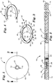
- FIG. 1 is a top planar view of an optical information storage disk in accordance with the present invention;
- FIG. 2 is a fragmentary, sectional view taken along line 2-2 of Fig. 1;
- FIG. 3 is an enlarged, perspective view of the magnetic marker in accordance with the present invention; and
- FIG. 4 is an enlarged, perspective view of an alternative embodiment of the magnetic marker in accordance with the present invention.
- Referring to the drawings, an optical
information storage disk 10 in accordance with the present invention broadly includes a generally planar, annularfirst disk surface 12, an opposed, annularsecond disk surface 14 oriented generally parallel to thefirst disk surface 12, and an annularmagnetic marker 16 carried within anannular groove 18 in thefirst disk surface 12. Centeredaperture 20 and circularperipheral rim 22 extend between thefirst surface 12 andsecond surface 14. Themagnetic marker 16 is concentrically oriented about the centeredaperture 20. - Information tracks 24 are made up of microscopic pits and smooth areas on the disk
first surface 12. Thetracks 24 can be either circular or helical and are concentrically oriented about the centeredaperture 20. - As shown in more detail in Figure 2, the
annular groove 18 presents a generally cylindrical grooveinner wall 26, an opposed generally cylindrical grooveouter wall 28, and a generallyannular bottom wall 30 extending between the grooveinner wall 26 andouter wall 28. The grooveinner wall 26 andouter wall 28 are both oriented generally normal to thefirst disk surface 12. Thegroove bottom wall 30 is recessed from, and oriented generally parallel to, thefirst disk surface 12. -
Magnetic marker 16 includes afirst annulus member 32 formed from a high permeability, low coercive force ferromagnetic material such as permalloy, supermalloy, or the like. Theannulus member 32 has anupper surface 34, alower surface 36, an innerperipheral rim 38, and an outerperipheral rim 40. - Four
internal notches 42 are formed on the internalperipheral rim 38 of theannulus 32. Thenotches 42 are spaced apart at approximately ninety degree intervals along therim 40. Fourexternal notches 44 are formed in the outerperipheral rim 40 of theannulus member 32 in opposed relationship with theinternal notches 42. The opposed pairs ofnotches sectional area 46 along theannulus 32.Flux collection regions 47 are created between theareas 46. - A
second annulus member 48 is adhesively coupled to, and is substantially coextensive with, thefirst annulus member 32. Thesecond annulus member 48 is formed from a sheet of relatively high coercive force ferromagnetic material such vicalloy, magnetic stainless steel, Chromendur II, or the like. Theannulus member 48 includes anupper surface 50, an opposed, lower surface 52 adhesively bonded to theupper surface 34 of thefirst annulus member 32, an innerperipheral rim 54 generally co-extensive with theinner rim 38 of thefirst annulus member 38, and anouter rim 56 co-extensive with theouter rim 40 of thefirst annulus member 32. - The
inner rim 38 of thefirst annulus member 32 and theinner rim 54 of thesecond annulus member 48 present a markerinner rim 58. Referring to Figure 2, the groove inner diameter presented by grooveinner wall 26 is matched to the inner diameter presented bymarker rim 58 such that themarker 16 is self-centered about the centeredaperture 20 ofdisk 10 by the engagement of theinner rim 58 ofmarker 16 with the grooveinner wall 26, while avoiding force fitting the marker, which could place mechanical stress on the marker. Theouter rim 40 offirst annulus member 32 andouter rim 56 ofannulus member 48 define a markerouter rim 60. The groove outer diameter presented by grooveouter wall 28 is similarly matched to the outer diameter ofmarker 16 presented by markerouter rim 60 such that themarker 16 is also self-centered about the disk centeredaperture 20 by engagement of the marker outerperipheral rim 60 with the grooveouter wall 28. - The
magnetic marker 16 can be retained within thegroove 18 by an adhesive bond applied between thelower surface 34 ofannulus member 32 and thegroove bottom wall 30. Acoating 62, such as a lacquer finish, applied to and carried by thefirst disk surface 12 is received within thegroove 18, and immovably positions themagnetic marker 16 within thegroove 18. - An alternate embodiment of the marker 16' is depicted in Figure 4. The marker 16' is similar in many respects to the
marker 16, and identical features between the two markers are annotated with identical numbers in the drawings, and similar but not identical features are indicated in Figure 4 with primed (') numbers. In this embodiment, the switching sections of the marker 16' are not created by physically removing material from the first annulus member 32'. Rather, the "notches" 42', 44' are formed by physically striking the annulus 32' at the points where the "notches" 42, 44 are desired, or by otherwise work hardening the annulus 32' at the desired points. In this way, the permeability of the material at those points is lowered so that the material can no longer magnetically reverse rapidly enough to create a characteristic response. - In use, the
marker 16 can be magnetically switched between a first state wherein it is responsive to a magnetic interrogation field to initiate an alarm as it is passed through the field, and a second state wherein it is unresponsive to the interrogation field. Themarker 16 is switched between an active and deactive state by uniformly magnetizing and demagnetizing thesecond annulus member 48 of themarker 16. More particularly, themarker 16 is reliably switched from a first, active state into a second, deactivated state, by substantially uniformly magnetizing themagnetizable member 48 so as to exhibit a first magnetic polarity along one end of themember 48 and an opposite polarity at the opposite end of themember 48. This essentially linear polarization is opposed to the generally annular physical shape of themember 48. It will be appreciated that themarker 16, although of relatively small size, provides a readily distinguishable response because of the presence offlux collector regions 47 presented by the pairs ofopposed notches first annulus member 32 ofmarker 16. - The optical
information storage disk 10 can be kept in an access controlled space, such as the display space of a retail store having entrance and egress to the space directed only through the magnetic field established by the panels of an electronic article surveillance system. Thedisks 10 would be stored with theirmagnetic markers 16 in the active state such that removal of a disk from the store, through the magnetic field, would set off an alarm. Upon proper check out of adisk 10 with a clerk, however, the clerk would deactivate themarker 16 such that its passage through the magnetic field would not initiate an alarm. - The
coating 62 effectively immovably seals themarker 16 within thegroove 18 without hindering the readability of the data tracks 24 on thedisk 10, since it would be difficult or impossible to remove themarker 16 without damaging the disk. Excess packaging techniques, such as use of the "longbox," can accordingly be dispensed with, without undesirably increasing the chance of unauthorized removal of a disk from a controlled space. - While the marker 16 (and the alternative embodiment of the marker 16') disclosed herein has been especially adapted for use with compact disks, it will be appreciated that the unique shape and magnetic orientation of the
marker 16 make it adaptable to other applications. For instance, the small size and annular shape of themarker 16 make it ideal for insertion into the cap of a container for pharmaceuticals, thereby providing for EAS monitoring of heretofore pilferable prescription and nonprescription drugs.
Claims (12)
- An optical information disk (10) of the general type comprising a generally planar, generally annular first disk surface (12) and an opposed, generally annular second disk surface (14) oriented generally parallel to said first disk surface (12), an outer, generally circular peripheral rim (22) extending between said first and second disk surfaces and structure defining a generally centered aperture (20) extending between said first and second disk surfaces and a plurality of generally concentric data tracks (24) optically accessible from at least one of said disk surfaces, wherein said disk is further adapted for use with a magnetic electronic surveillance system to prevent unauthorized removal of said disk from an access restricted location, said disk further comprising a generally annular magnetic marker (16) adapted for use with said electronic article surveillance system carried about said aperture and means (62) for immovably retaining said marker without impairing the operability of said disk.
- A disk according to claim 1, wherein said disk includes structure (18) defining a groove in said first disk surface including a generally cylindrical groove inner wall (26) oriented generally normal to said first disk surface, an opposed, generally cylindrical groove outer wall (28) oriented generally normal to said first disk surface, and a generally annular bottom wall (30) oriented generally parallel to said first disk surface extending between said inner and outer groove walls and wherein said marker (16) is positioned within said groove.
- A disk according to claim 1 or 2, said marker (16) including a generally annular marker (32) having an upper surface (34) and an opposed, generally annular marker lower surface (36), said means for immovably retaining said marker including adhesive means for adhering said marker lower surface to said groove bottom wall.
- A disk according to any one of claims 1 to 3, said means (62) for immovably retaining said marker (16) including a sealing compound applied across said first surface and bondingly received within said groove for immovably sealing said marker in said groove.
- A disk according to claim 4, said sealing compound comprising a lacquer coating.
- A disk according to any one of claims 1 to 5, wherein said marker (16) comprises:(a) a first annulus (32) of a high permeability, low coercive force material having a plurality of magnetic switching areas (42) into which flux collected from adjacent areas is concentrated, thereby enabling a characteristic, readily distinguishable response to be created upon reversal of the magnetic state within at least one switching area; and(b) a second annulus (48) substantially coextensive with said first annulus and formed of a relatively high coercive force material which, when magnetized, alters said characteristic response from that resulting when unmagnetized.
- A marker (16) adapted for use in an electronic article surveillance system having in an interrogation zone an alternating magnetic field, comprising:(a) a first annulus (32) of a high permeability, low coercive force material having a plurality of magnetic switching areas (46) into which flux collected from adjacent areas is concentrated, thereby enabling a characteristic, readily distinguishable response to be created upon reversal of the magnetic state within at least one switching area when said marker is placed within said interrogation zone; and(b) a second annulus (48) substantially coextensive with said first annulus and formed of a relatively high coercive force material magnetizable in an essentially linear direction which, when magnetized, alters said characteristic response of said marker within said interrogation zone from the response resulting when unmagnetized.
- A marker according to claim 7, said first annulus (32) presenting a generally annular inner rim (38) and a generally annular outer rim (40), said magnetic switching areas (46) comprising regions of reduced cross-sectional area.
- A marker according to claim 7, said regions of reduced cross-sectional area comprising structure defining notches (42 and 44) in said first annulus (32).
- A marker according to any one of claims 7 to 9, said first annulus (32) presenting a generally annular inner rim and a generally annular outer rim, said magnetic switching areas (46) comprising regions within which the magnetic response is permanently altered.
- A marker according to any one of claims 7 to 10, said altered magnetic response being provided by areas (46) in which the low coercive material is work hardened to decrease the permeability therein.
- A marker according to any one of claims 7 to 11, said magnetic switching areas (46) being oriented about said first annulus (32) at about ninety degree intervals.
Applications Claiming Priority (2)
| Application Number | Priority Date | Filing Date | Title |
|---|---|---|---|
| US07/872,151 US5347508A (en) | 1992-04-22 | 1992-04-22 | Optical information storage disk for use with electronic article surveillance systems |
| US872151 | 1992-04-22 |
Publications (2)
| Publication Number | Publication Date |
|---|---|
| EP0567080A1 true EP0567080A1 (en) | 1993-10-27 |
| EP0567080B1 EP0567080B1 (en) | 1998-12-16 |
Family
ID=25358951
Family Applications (1)
| Application Number | Title | Priority Date | Filing Date |
|---|---|---|---|
| EP93106403A Expired - Lifetime EP0567080B1 (en) | 1992-04-22 | 1993-04-20 | Optical information storage disk for use with electronic article surveillance systems |
Country Status (7)
| Country | Link |
|---|---|
| US (1) | US5347508A (en) |
| EP (1) | EP0567080B1 (en) |
| JP (1) | JP3332461B2 (en) |
| KR (1) | KR100276576B1 (en) |
| AU (1) | AU662607B2 (en) |
| CA (1) | CA2092358C (en) |
| DE (1) | DE69322540T2 (en) |
Cited By (9)
| Publication number | Priority date | Publication date | Assignee | Title |
|---|---|---|---|---|
| EP0704828A1 (en) * | 1994-09-28 | 1996-04-03 | Sensormatic Electronics Corporation | Magnetomechanical EAS components integrated with a retail product or product packaging |
| EP0732691A1 (en) * | 1995-03-16 | 1996-09-18 | Kabushiki Kaisha Toshiba | Optical disk structure, method of manufacturing the same, and apparatus for manufacturing the same |
| EP0789339A3 (en) * | 1996-02-06 | 1998-06-03 | Meto International GmbH | Securing element for the electronic protection of articles |
| WO1998047139A2 (en) * | 1997-04-11 | 1998-10-22 | Walter Schlutius | Method and device for aligning a data carrier disk provided with an overprint, and corresponding data carrier disks |
| WO1999010888A1 (en) * | 1997-08-27 | 1999-03-04 | Valmark Industries, Inc. | Write-protect component for re-writable compact discs |
| NL1010200C2 (en) * | 1998-09-28 | 2000-04-03 | Od & Me Bv | Optical disc assembly with two standard discs and an additional recorded area which inhibits fraudulent copying of data |
| EP1030303A2 (en) * | 1999-02-18 | 2000-08-23 | PERSONAL VIDEO ITALIA di Battilani Giancarlo | Disk-shaped record carrier provided with a circular identification code |
| GB2377920A (en) * | 2001-07-25 | 2003-01-29 | Entertainment Uk Ltd | Cover and security tag fixed directly to an optical disc |
| FR2883405A1 (en) * | 2005-03-15 | 2006-09-22 | Digital Valley | Optical disk e.g. digital versatile disk, fabricating method for electronic article monitoring system, involves inserting antenna between two disk layers along disk axis, and forming substrates with pouch around inner hole to accept antenna |
Families Citing this family (47)
| Publication number | Priority date | Publication date | Assignee | Title |
|---|---|---|---|---|
| US5699047A (en) * | 1996-01-19 | 1997-12-16 | Minnesota Mining And Manufacturing Co. | Electronic article surveillance markers for direct application to optically recorded media |
| US5899886A (en) * | 1997-07-07 | 1999-05-04 | Cosme; Edgar Z. | Puncture safe needle assembly |
| US5940362A (en) * | 1996-08-19 | 1999-08-17 | Sensormatic Electronics Corporation | Disc device having a magnetic layer overweighing the information signal pattern for electronic article surveillance |
| US6608561B2 (en) * | 1998-05-19 | 2003-08-19 | Meat Processing Service Corp., Inc. | Method for making a radio frequency identification device |
| AU4839899A (en) * | 1998-06-29 | 2000-01-17 | Recording Industry Association Of America | Security marking system and method for minimizing pirating of data on data media |
| US6199309B1 (en) * | 1998-10-06 | 2001-03-13 | Contempo Card Company, Inc. | Merchandising markers accomodating anti-theft sensor |
| US6525661B2 (en) | 1999-02-26 | 2003-02-25 | 3M Innovative Properties Company | Electronic article surveillance markers for optically recorded media |
| US6941383B1 (en) | 2000-01-20 | 2005-09-06 | Interactual Technologies, Inc. | System, method and article of manufacture for java/javascript component in a multimedia synchronization framework |
| US6769130B1 (en) * | 2000-01-20 | 2004-07-27 | Interactual Technologies, Inc. | System, method and article of manufacture for late synchronization during the execution of a multimedia event on a plurality of client computers |
| US7188193B1 (en) | 2000-01-20 | 2007-03-06 | Sonic Solutions, A California Corporation | System, method and article of manufacture for a synchronizer component in a multimedia synchronization framework |
| US7178106B2 (en) * | 1999-04-21 | 2007-02-13 | Sonic Solutions, A California Corporation | Presentation of media content from multiple media sources |
| US6665489B2 (en) | 1999-04-21 | 2003-12-16 | Research Investment Network, Inc. | System, method and article of manufacturing for authorizing the use of electronic content utilizing a laser-centric medium and a network server |
| CN1367926A (en) * | 1999-04-21 | 2002-09-04 | 研究投资网络公司 | System, emthod and article of manufacture for updating content stored on portable storage medium |
| US7448021B1 (en) | 2000-07-24 | 2008-11-04 | Sonic Solutions, A California Corporation | Software engine for combining video or audio content with programmatic content |
| US7346920B2 (en) * | 2000-07-07 | 2008-03-18 | Sonic Solutions, A California Corporation | System, method and article of manufacture for a common cross platform framework for development of DVD-Video content integrated with ROM content |
| US6529949B1 (en) * | 2000-02-07 | 2003-03-04 | Interactual Technologies, Inc. | System, method and article of manufacture for remote unlocking of local content located on a client device |
| US20060193606A1 (en) * | 1999-04-21 | 2006-08-31 | Interactual Technologies, Inc. | Two navigation |
| US20050198574A1 (en) * | 1999-04-21 | 2005-09-08 | Interactual Technologies, Inc. | Storyboard |
| US7458091B1 (en) | 2000-01-20 | 2008-11-25 | Sonic Solutions, A California Corporation | System, method and article of manufacture for a business layer component in a multimedia synchronization framework |
| US6453420B1 (en) | 1999-04-21 | 2002-09-17 | Research Investment Network, Inc. | System, method and article of manufacture for authorizing the use of electronic content utilizing a laser-centric medium |
| US20060041639A1 (en) * | 1999-04-21 | 2006-02-23 | Interactual Technologies, Inc. | Platform detection |
| US6405203B1 (en) | 1999-04-21 | 2002-06-11 | Research Investment Network, Inc. | Method and program product for preventing unauthorized users from using the content of an electronic storage medium |
| US20050182828A1 (en) * | 1999-04-21 | 2005-08-18 | Interactual Technologies, Inc. | Platform specific execution |
| US20040220926A1 (en) * | 2000-01-03 | 2004-11-04 | Interactual Technologies, Inc., A California Cpr[P | Personalization services for entities from multiple sources |
| US7392481B2 (en) * | 2001-07-02 | 2008-06-24 | Sonic Solutions, A California Corporation | Method and apparatus for providing content-owner control in a networked device |
| US20040220791A1 (en) * | 2000-01-03 | 2004-11-04 | Interactual Technologies, Inc. A California Corpor | Personalization services for entities from multiple sources |
| US6957220B2 (en) | 2000-11-07 | 2005-10-18 | Research Investment Networks, Inc. | System, method and article of manufacture for tracking and supporting the distribution of content electronically |
| US20050251732A1 (en) * | 2000-01-20 | 2005-11-10 | Interactual Technologies, Inc. | System, method and article of manufacture for executing a multimedia event on a plurality of client computers using a synchronization host engine |
| KR200197266Y1 (en) * | 2000-04-11 | 2000-09-15 | 김선득 | Recording media comprising sensing device for antitheft |
| US7689510B2 (en) | 2000-09-07 | 2010-03-30 | Sonic Solutions | Methods and system for use in network management of content |
| US7779097B2 (en) | 2000-09-07 | 2010-08-17 | Sonic Solutions | Methods and systems for use in network management of content |
| US7191442B2 (en) * | 2000-10-30 | 2007-03-13 | Research Investment Network, Inc. | BCA writer serialization management |
| US6716589B2 (en) | 2000-11-20 | 2004-04-06 | Alphabeta Ab | Discordant helix stabilization for prevention of amyloid formation |
| US6614750B2 (en) | 2001-02-28 | 2003-09-02 | Warren Weber | Optical recordable disk security system |
| US7017190B2 (en) * | 2001-03-21 | 2006-03-21 | Weber Warren D | Portable recordable media anti-theft system |
| US6693542B2 (en) * | 2001-11-15 | 2004-02-17 | Ryusuke Hasegawa | Electronic article surveillance markers for recorded media |
| US6775839B1 (en) | 2002-03-15 | 2004-08-10 | O'brien Patrick J. | Optical storage device with print layer surface feature |
| US20040052203A1 (en) * | 2002-09-13 | 2004-03-18 | Brollier Brian W. | Light enabled RFID in information disks |
| US7187645B2 (en) * | 2003-03-17 | 2007-03-06 | Vidco, Inc. | Secure optical information disc having a minimized metal layer |
| US6947371B2 (en) * | 2003-03-17 | 2005-09-20 | Deluxe Media Services | Secure optical information disc |
| WO2004099821A1 (en) * | 2003-05-07 | 2004-11-18 | Kenetics Innovations Pte Ltd | A method and apparatus for enhancing performance of an rfid tag for a compact disc |
| US7823781B2 (en) * | 2003-05-23 | 2010-11-02 | Enxnet, Inc. | Method and system for source tagging an optical storage device |
| WO2006096367A2 (en) | 2005-03-03 | 2006-09-14 | Enxnet, Inc. | Optical disc having a reduced planar thickness |
| JP2009512106A (en) * | 2005-10-07 | 2009-03-19 | エンクスネット,インコーポレイテッド | Thin optical disc that can be read remotely |
| US7716695B2 (en) * | 2005-10-07 | 2010-05-11 | Enxnet, Inc. | Thin optical disc having remote reading capability |
| US7555715B2 (en) * | 2005-10-25 | 2009-06-30 | Sonic Solutions | Methods and systems for use in maintaining media data quality upon conversion to a different data format |
| US20070200187A1 (en) * | 2006-02-28 | 2007-08-30 | Amlani Islamshah S | Nanowire device and method of making |
Citations (3)
| Publication number | Priority date | Publication date | Assignee | Title |
|---|---|---|---|---|
| US4910625A (en) * | 1988-10-11 | 1990-03-20 | Eastman Kodak Company | Article surveillance apparatus and systems for computer data disks |
| US5012380A (en) * | 1989-08-24 | 1991-04-30 | Eastman Kodak Company | Article surveillance protection of flexible magnetic computer data storage disks |
| US5081446A (en) * | 1990-09-24 | 1992-01-14 | Checkpoint Systems, Inc. | Security tag for compact disc storage container |
Family Cites Families (5)
| Publication number | Priority date | Publication date | Assignee | Title |
|---|---|---|---|---|
| US4692746A (en) * | 1986-02-26 | 1987-09-08 | Security Tag Systems, Inc. | Recording-tape-reel assembly with electronic tag |
| US4709813A (en) * | 1986-04-10 | 1987-12-01 | Minnesota Mining And Manufacturing Company | Anti-theft device for compact discs |
| US4794470A (en) * | 1986-06-25 | 1988-12-27 | Media Security Incorporated And Associates | Security system for protecting information |
| US4710754A (en) * | 1986-09-19 | 1987-12-01 | Minnesota Mining And Manufacturing Company | Magnetic marker having switching section for use in electronic article surveillance systems |
| US4967185A (en) * | 1989-08-08 | 1990-10-30 | Minnesota Mining And Manufacturing Company | Multi-directionally responsive, dual-status, magnetic article surveillance marker having continuous keeper |
-
1992
- 1992-04-22 US US07/872,151 patent/US5347508A/en not_active Expired - Lifetime
-
1993
- 1993-03-22 AU AU35396/93A patent/AU662607B2/en not_active Ceased
- 1993-03-24 CA CA002092358A patent/CA2092358C/en not_active Expired - Fee Related
- 1993-04-19 KR KR1019930006538A patent/KR100276576B1/en not_active IP Right Cessation
- 1993-04-19 JP JP09117193A patent/JP3332461B2/en not_active Expired - Fee Related
- 1993-04-20 DE DE69322540T patent/DE69322540T2/en not_active Expired - Fee Related
- 1993-04-20 EP EP93106403A patent/EP0567080B1/en not_active Expired - Lifetime
Patent Citations (3)
| Publication number | Priority date | Publication date | Assignee | Title |
|---|---|---|---|---|
| US4910625A (en) * | 1988-10-11 | 1990-03-20 | Eastman Kodak Company | Article surveillance apparatus and systems for computer data disks |
| US5012380A (en) * | 1989-08-24 | 1991-04-30 | Eastman Kodak Company | Article surveillance protection of flexible magnetic computer data storage disks |
| US5081446A (en) * | 1990-09-24 | 1992-01-14 | Checkpoint Systems, Inc. | Security tag for compact disc storage container |
Cited By (13)
| Publication number | Priority date | Publication date | Assignee | Title |
|---|---|---|---|---|
| EP0704828A1 (en) * | 1994-09-28 | 1996-04-03 | Sensormatic Electronics Corporation | Magnetomechanical EAS components integrated with a retail product or product packaging |
| US6019863A (en) * | 1995-03-16 | 2000-02-01 | Kabushiki Kaisha Toshiba | Optical disk structure, method of manufacturing the same, and apparatus for manufacturing the same |
| EP0732691A1 (en) * | 1995-03-16 | 1996-09-18 | Kabushiki Kaisha Toshiba | Optical disk structure, method of manufacturing the same, and apparatus for manufacturing the same |
| EP0789339A3 (en) * | 1996-02-06 | 1998-06-03 | Meto International GmbH | Securing element for the electronic protection of articles |
| WO1998047139A2 (en) * | 1997-04-11 | 1998-10-22 | Walter Schlutius | Method and device for aligning a data carrier disk provided with an overprint, and corresponding data carrier disks |
| WO1998047139A3 (en) * | 1997-04-11 | 1999-02-11 | Walter Schlutius | Method and device for aligning a data carrier disk provided with an overprint, and corresponding data carrier disks |
| WO1999010888A1 (en) * | 1997-08-27 | 1999-03-04 | Valmark Industries, Inc. | Write-protect component for re-writable compact discs |
| NL1010200C2 (en) * | 1998-09-28 | 2000-04-03 | Od & Me Bv | Optical disc assembly with two standard discs and an additional recorded area which inhibits fraudulent copying of data |
| EP1030303A2 (en) * | 1999-02-18 | 2000-08-23 | PERSONAL VIDEO ITALIA di Battilani Giancarlo | Disk-shaped record carrier provided with a circular identification code |
| EP1030303A3 (en) * | 1999-02-18 | 2000-10-18 | PERSONAL VIDEO ITALIA di Battilani Giancarlo | Disk-shaped record carrier provided with a circular identification code |
| GB2377920A (en) * | 2001-07-25 | 2003-01-29 | Entertainment Uk Ltd | Cover and security tag fixed directly to an optical disc |
| GB2377920B (en) * | 2001-07-25 | 2005-05-18 | Entertainment Uk Ltd | Cover and security tag fixed directly to an optical discs |
| FR2883405A1 (en) * | 2005-03-15 | 2006-09-22 | Digital Valley | Optical disk e.g. digital versatile disk, fabricating method for electronic article monitoring system, involves inserting antenna between two disk layers along disk axis, and forming substrates with pouch around inner hole to accept antenna |
Also Published As
| Publication number | Publication date |
|---|---|
| AU3539693A (en) | 1993-10-28 |
| CA2092358A1 (en) | 1993-10-23 |
| JP3332461B2 (en) | 2002-10-07 |
| US5347508A (en) | 1994-09-13 |
| JPH0644738A (en) | 1994-02-18 |
| DE69322540D1 (en) | 1999-01-28 |
| KR100276576B1 (en) | 2001-01-15 |
| CA2092358C (en) | 2004-07-06 |
| DE69322540T2 (en) | 1999-08-19 |
| KR930022291A (en) | 1993-11-23 |
| EP0567080B1 (en) | 1998-12-16 |
| AU662607B2 (en) | 1995-09-07 |
Similar Documents
| Publication | Publication Date | Title |
|---|---|---|
| US5347508A (en) | Optical information storage disk for use with electronic article surveillance systems | |
| WO1998010386A9 (en) | Disc-like device with eas material | |
| CA2021792C (en) | Multi-directionally responsive, dual-status, magnetic article surveillance marker having continuous keeper | |
| US5477219A (en) | Composite electronic article surveillance, identification, and security marker assembly and system | |
| EP0260831B1 (en) | Dual-status, magnetically imagable article surveillance marker | |
| US5499015A (en) | Magnetomechanical EAS components integrated with a retail product or product packaging | |
| US5871100A (en) | Security battery package | |
| DE4242992B4 (en) | Arrangement for securing an article, in particular a recording disk such as a CD disk | |
| US4811000A (en) | Article enclosure with magnetic marker deactivating means | |
| US6614750B2 (en) | Optical recordable disk security system | |
| AU729410B2 (en) | Disc-like device with EAS material | |
| JP3419842B2 (en) | Low sensitivity device for electromagnetic product monitoring system | |
| US5432499A (en) | Collector type article surveillance marker with continuous keeper | |
| US7823781B2 (en) | Method and system for source tagging an optical storage device | |
| WO2003044754A1 (en) | Electronic article surveillance markers for recorded media | |
| AU734864B2 (en) | Apparatus for deactivating magnetomechanical EAS markers affixed to magnetic recording medium products | |
| US6525661B2 (en) | Electronic article surveillance markers for optically recorded media | |
| AU718179B2 (en) | Magnetomechanical EAS components integrated with a retail product or product packaging |
Legal Events
| Date | Code | Title | Description |
|---|---|---|---|
| PUAI | Public reference made under article 153(3) epc to a published international application that has entered the european phase |
Free format text: ORIGINAL CODE: 0009012 |
|
| AK | Designated contracting states |
Kind code of ref document: A1 Designated state(s): DE FR GB IT NL SE |
|
| 17P | Request for examination filed |
Effective date: 19940423 |
|
| 17Q | First examination report despatched |
Effective date: 19960813 |
|
| GRAG | Despatch of communication of intention to grant |
Free format text: ORIGINAL CODE: EPIDOS AGRA |
|
| GRAG | Despatch of communication of intention to grant |
Free format text: ORIGINAL CODE: EPIDOS AGRA |
|
| GRAH | Despatch of communication of intention to grant a patent |
Free format text: ORIGINAL CODE: EPIDOS IGRA |
|
| GRAH | Despatch of communication of intention to grant a patent |
Free format text: ORIGINAL CODE: EPIDOS IGRA |
|
| GRAA | (expected) grant |
Free format text: ORIGINAL CODE: 0009210 |
|
| AK | Designated contracting states |
Kind code of ref document: B1 Designated state(s): DE FR GB IT NL SE |
|
| REF | Corresponds to: |
Ref document number: 69322540 Country of ref document: DE Date of ref document: 19990128 |
|
| ET | Fr: translation filed | ||
| ITF | It: translation for a ep patent filed |
Owner name: ING. C. GREGORJ S.P.A. |
|
| PLBE | No opposition filed within time limit |
Free format text: ORIGINAL CODE: 0009261 |
|
| STAA | Information on the status of an ep patent application or granted ep patent |
Free format text: STATUS: NO OPPOSITION FILED WITHIN TIME LIMIT |
|
| 26N | No opposition filed | ||
| PGFP | Annual fee paid to national office [announced via postgrant information from national office to epo] |
Ref country code: NL Payment date: 20010412 Year of fee payment: 9 |
|
| REG | Reference to a national code |
Ref country code: GB Ref legal event code: IF02 |
|
| PG25 | Lapsed in a contracting state [announced via postgrant information from national office to epo] |
Ref country code: NL Free format text: LAPSE BECAUSE OF NON-PAYMENT OF DUE FEES Effective date: 20021101 |
|
| NLV4 | Nl: lapsed or anulled due to non-payment of the annual fee |
Effective date: 20021101 |
|
| PG25 | Lapsed in a contracting state [announced via postgrant information from national office to epo] |
Ref country code: IT Free format text: LAPSE BECAUSE OF NON-PAYMENT OF DUE FEES;WARNING: LAPSES OF ITALIAN PATENTS WITH EFFECTIVE DATE BEFORE 2007 MAY HAVE OCCURRED AT ANY TIME BEFORE 2007. THE CORRECT EFFECTIVE DATE MAY BE DIFFERENT FROM THE ONE RECORDED. Effective date: 20050420 |
|
| REG | Reference to a national code |
Ref country code: HK Ref legal event code: WD Ref document number: 1014292 Country of ref document: HK |
|
| PGFP | Annual fee paid to national office [announced via postgrant information from national office to epo] |
Ref country code: DE Payment date: 20080602 Year of fee payment: 16 |
|
| PGFP | Annual fee paid to national office [announced via postgrant information from national office to epo] |
Ref country code: SE Payment date: 20080429 Year of fee payment: 16 |
|
| PGFP | Annual fee paid to national office [announced via postgrant information from national office to epo] |
Ref country code: FR Payment date: 20080417 Year of fee payment: 16 |
|
| PGFP | Annual fee paid to national office [announced via postgrant information from national office to epo] |
Ref country code: GB Payment date: 20080429 Year of fee payment: 16 |
|
| EUG | Se: european patent has lapsed | ||
| GBPC | Gb: european patent ceased through non-payment of renewal fee |
Effective date: 20090420 |
|
| REG | Reference to a national code |
Ref country code: FR Ref legal event code: ST Effective date: 20091231 |
|
| PG25 | Lapsed in a contracting state [announced via postgrant information from national office to epo] |
Ref country code: DE Free format text: LAPSE BECAUSE OF NON-PAYMENT OF DUE FEES Effective date: 20091103 |
|
| PG25 | Lapsed in a contracting state [announced via postgrant information from national office to epo] |
Ref country code: GB Free format text: LAPSE BECAUSE OF NON-PAYMENT OF DUE FEES Effective date: 20090420 Ref country code: FR Free format text: LAPSE BECAUSE OF NON-PAYMENT OF DUE FEES Effective date: 20091222 |
|
| PG25 | Lapsed in a contracting state [announced via postgrant information from national office to epo] |
Ref country code: SE Free format text: LAPSE BECAUSE OF NON-PAYMENT OF DUE FEES Effective date: 20090421 |