EP0564264B1 - Illumination device for projection exposure apparatus - Google Patents
Illumination device for projection exposure apparatus Download PDFInfo
- Publication number
- EP0564264B1 EP0564264B1 EP93302508A EP93302508A EP0564264B1 EP 0564264 B1 EP0564264 B1 EP 0564264B1 EP 93302508 A EP93302508 A EP 93302508A EP 93302508 A EP93302508 A EP 93302508A EP 0564264 B1 EP0564264 B1 EP 0564264B1
- Authority
- EP
- European Patent Office
- Prior art keywords
- optical
- light source
- light
- integrator
- deflecting member
- Prior art date
- Legal status (The legal status is an assumption and is not a legal conclusion. Google has not performed a legal analysis and makes no representation as to the accuracy of the status listed.)
- Expired - Lifetime
Links
Images


Classifications
-
- G—PHYSICS
- G03—PHOTOGRAPHY; CINEMATOGRAPHY; ANALOGOUS TECHNIQUES USING WAVES OTHER THAN OPTICAL WAVES; ELECTROGRAPHY; HOLOGRAPHY
- G03F—PHOTOMECHANICAL PRODUCTION OF TEXTURED OR PATTERNED SURFACES, e.g. FOR PRINTING, FOR PROCESSING OF SEMICONDUCTOR DEVICES; MATERIALS THEREFOR; ORIGINALS THEREFOR; APPARATUS SPECIALLY ADAPTED THEREFOR
- G03F7/00—Photomechanical, e.g. photolithographic, production of textured or patterned surfaces, e.g. printing surfaces; Materials therefor, e.g. comprising photoresists; Apparatus specially adapted therefor
- G03F7/70—Microphotolithographic exposure; Apparatus therefor
- G03F7/70058—Mask illumination systems
- G03F7/70091—Illumination settings, i.e. intensity distribution in the pupil plane or angular distribution in the field plane; On-axis or off-axis settings, e.g. annular, dipole or quadrupole settings; Partial coherence control, i.e. sigma or numerical aperture [NA]
- G03F7/70108—Off-axis setting using a light-guiding element, e.g. diffractive optical elements [DOEs] or light guides
-
- G—PHYSICS
- G03—PHOTOGRAPHY; CINEMATOGRAPHY; ANALOGOUS TECHNIQUES USING WAVES OTHER THAN OPTICAL WAVES; ELECTROGRAPHY; HOLOGRAPHY
- G03F—PHOTOMECHANICAL PRODUCTION OF TEXTURED OR PATTERNED SURFACES, e.g. FOR PRINTING, FOR PROCESSING OF SEMICONDUCTOR DEVICES; MATERIALS THEREFOR; ORIGINALS THEREFOR; APPARATUS SPECIALLY ADAPTED THEREFOR
- G03F7/00—Photomechanical, e.g. photolithographic, production of textured or patterned surfaces, e.g. printing surfaces; Materials therefor, e.g. comprising photoresists; Apparatus specially adapted therefor
- G03F7/70—Microphotolithographic exposure; Apparatus therefor
- G03F7/70216—Mask projection systems
- G03F7/70241—Optical aspects of refractive lens systems, i.e. comprising only refractive elements
Definitions
- This invention relates to an illumination device and a projection exposure apparatus.using the same. More particularly, the invention is concerned with an illumination device usable in a microdevice manufacturing exposure apparatus (called a stepper) for illuminating a pattern formed on a reticle in a manner easily attaining high resolution. In another aspect, the invention is concerned with a projection exposure apparatus using such an illumination device.
- a microdevice manufacturing exposure apparatus called a stepper
- the depth of focus of a stepper is in inverse proportion to the square of the NA.
- enhancing the resolution into a submicron order necessarily results in a problem of decreased depth of focus.
- Annular light patterns are achieved in the article by placing a stop having an annular aperture with a central circular blocking region adjacent the light exit surface of the integrator. Light exits the integrators, but can only pass through the annular portion of the stop. A proportion of the light is blocked, leading to reduced illumination levels on the final substrate.
- the present invention improves the efficiency of annular illumination devices by directing a greater proportion of the light from the source into the required annular region when high resolution is required.
- EP-A-0507487 an earlier European patent application which was published after the priority date of the present patent, describes an illumination system wherein an annular bundle of rays is passed through a conical lens 77 to increase the radius of the annular bundle. Annular lenses then concentrate the ray bundle to form a high-intensity annular ray of large radius and small radial thickness. The annular ray is used as a light source to illuminate a mask for projection at high resolution.
- Practical semiconductor device manufacturing processes include on one hand a process wherein high resolution of a pattern is required and, on the other hand, a process wherein a not so high resolution of a pattern is required.
- the present invention aims to provide a projection exposure apparatus which can meet the requirement of various resolution performances to be satisfied in various processes.
- the present invention provides an illumination system wherein light from a primary light source is projected to an optical integrator whereby a secondary light source is formed, and wherein lights from the secondary light source are projected to a surface, to be illuminated, by an optical system whereby they are superposed one upon another, characterized in that: a deflecting member having a conical light deflection surface is demountably disposed between the primary light source and the optical integrator, the deflecting member serving to transform the light from the deflecting member serving to transform the light from the primary light source into an annular light pattern which is projected to the optical integrator to form an annular secondary light source when the deflecting member is present.
- the invention provides a method of manufacturing microdevices such as semiconductor memories, liquid crystal panels, magnetic heads or CCDs, for example, using an illumination device such as above.
- the invention provides an exposure apparatus for manufacture of microdevices that uses an illumination device such as above.
- the deflecting member usable in the present invention may be of the type that it refracts light at its light deflecting surface to shape or divide the light, or that it reflects the light at its deflecting surface to shape or divide the light.
- Figure 1 is a schematic view of a main portion of a first embodiment of the present invention.
- Figures 2A, 2B and 2C are schematic views, respectively, for explaining a portion of Figure 1.
- Figures 3A, 3B and 3C are schematic views, respectively, for explaining a portion of Figure 1.
- Figure 4 is a schematic view for explaining the optical function of a lens system 9 of Figure 1.
- Figure 5 is a schematic view for further explaining the optical function of the lens system 9 of Figure 1.
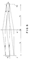
- Figure 6 is a schematic view for further explaining the optical function of the lens system 9 of Figure 1.
- Figure 7 is a schematic view of a portion of a second embodiment of the present invention.
- Figures 8, 9 and 10 are schematic views, respectively, each for explaining a portion of a third embodiment of the present invention.
- Figures 11A and 11B are schematic views, respectively, each for explaining the optical function of the third embodiment.
- Figures 12A and 12B are schematic views, respectively, each for further explaining the optical function of the third embodiment.
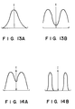
- Figures 13A and 13B are graphs, respectively, each showing an example of light intensity distribution in the third embodiment of the present invention.
- Figures 14A and 14B are graphs, respectively, each showing a further example of light intensity distribution in the third embodiment of the present invention.
- Figures 15A - 15C are schematic views, respectively, each showing a main portion of a fourth embodiment of the present invention.
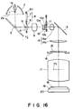
- Figure 16 is a schematic view of a main portion of a fifth embodiment of the present invention.
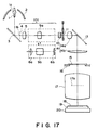
- Figure 17 is a schematic view of a main portion of a sixth embodiment of the present invention.
- Figure 18 is a schematic view for explaining a portion of Figure 17.
- Figure 19 is a schematic view for further explaining a portion of Figure 17.
- Figures 20A - 20C are schematic views, respectively, each for explaining the state of incidence of light upon a light entrance plane 10a of an optical integrator 10 of Figure 17.
- Figure 21 is a schematic view of an apertured stop.
- Figure 22 is a schematic view of a main portion of a seventh embodiment of the present invention.
- Figure 1 is a schematic view of an illumination device and a projection exposure apparatus using the same, according to an embodiment of the present invention.
- the invention is applied to a reduction projection type exposure apparatus, called a stepper.
- This exposure apparatus can be used for manufacture of microdevices such as semiconductor memories, CCDs, liquid crystal panels or magnetic head, for example.
- a light source such as a high luminance ultra high pressure Hg lamp, for example, for emitting ultraviolet light or deep UV light.
- the light source 1 has its light emitting portion 1a disposed adjacent to the first focal point of an elliptical mirror 2.
- the light emanating from the light source 1 is reflected and collected by the elliptical mirror 2, and then it is reflected by a cold mirror 3 by which an image 1b of the light emitting portion 1a (an image of light source) is formed in the neighbourhood of the second focal point 4 of the elliptical mirror 2.
- the cold mirror 3 has a multilayered film and it mainly serves to transmit infrared light but to reflect ultraviolet light.
- Denoted at 101 is an imaging system having two lens systems 5 and 9. It serves to image the light source image 1b, formed in the neighbourhood of the second focal point 4, upon an entrance plane 10a of an optical integrator 10 through the cooperation of an optical device 8.
- the optical device 8 comprises a prism member 6 having a conical prism, for deflecting received light to a predetermined direction, and a parallel flat plate 7 for projecting received light directly.
- Denoted at 8a is a holding member by which the prism member 6 and the parallel plate 7 of the optical device 8 can be alternately and selectively placed on the light path.
- the imaging system 101 is defined as an telecentric system on the exit side.
- the optical device 8 is disposed in the neighbourhood of the pupil plane of the imaging system, where the opening of the elliptical mirror is imaged.
- the optical integrator 10 comprises a plurality of small lenses which are arrayed two-dimensionally, and it serves to define a secondary light source 10c in the neighbourhood of the exit surface 10b thereof.
- Denoted at 11 is a stop member having a plurality of apertures.
- the stop member is provided with a mechanism by which the shape of aperture on the light path can be changed.
- the stop member 11 is disposed in such region in which discrete secondary light source elements do not overlap.
- Denoted at 14a is a lens system for collecting the light from the exit surface 10b of the optical integrator 10 and for illuminating, through the stop member 11 and a mirror 13 as well as a collimator lens 14b, a reticle (surface to be illuminated) 15 placed on a reticle stage 16.
- the lens system 14a and the collimator lens 14b constitute a condensing lens system 14.
- Denoted at 17 is a projection optical system for projecting, in a reduced scale, a pattern formed on the reticle 15 upon the surface of a wafer 18 which is placed on a wafer chuck 19.
- Denoted at 20 is a water stage on which the wafer chuck 19 is mounted.
- an image of the secondary light source 10c formed in the neighbourhood of the exit surface 10b of the optical integrator 10 is formed in the neighbourhood of a pupil 17a of the projection optical system 17.
- Figures 2A and 3A each illustrates the light path from the elliptical mirror 2 ( Figure 1) to the optical integrator 10, the path being extended.
- the mirror 3 is not shown in Figure 2A or 3A.
- the illustrations of Figures 2A - 2C and 3A - 3C explain that the light intensity distribution upon the entrance surface 10a of the optical integrator 10 is changed by alternately selecting the elements 6 and 7 of the optical device 8.
- Figures 2A - 2C correspond to a case where the parallel plate 7 of the optical device 8 is disposed on the light path
- Figures 3A - 3C correspond to a case where the prism member 6 of the optical device 8 is disposed on the light path.
- the illumination system of Figure 2A is adapted for a first state of projection in which a very high resolution is not required but in which a larger depth of focus is assured.
- the illumination system of Figure 3A is adapted for a second state of projection in which a high resolution is required mainly.
- Figures 2C and 3C each is a schematic representation of light intensity distribution upon the light entrance surface 10a of the optical integrator 10.
- the zone depicted by hatching in the drawings denotes the region of higher light intensity, as compared with the remaining region.
- Figures 2B and 3B illustrate distribution of light intensity I along the X-axis direction ( Figure 2C or 3C).
- the parallel plate 7 of the optical device 8 is disposed on the light path, and the light source image 1b as formed at the second focal point 4 of the elliptical mirror 2 is imaged by the imaging system 101 upon the light entrance surface 10a of the optical integrator 10.
- the light intensity distribution in section upon the light entrance surface 10a of the optical integrator 10 has an approximately Gaussian shape which is rotationally symmetric.
- the prism member 6 of the optical device 8 is placed on the light path, and the light source image (point image) 1b formed at the second focal point 4 of the elliptical mirror 2 is imaged, into a ring-like shape, on the light entrance surface 10a of the optical integrator 10 by the imaging system 101.
- the light intensity distribution on the light entrance surface 10a of the integrator 10 has a ring-like shape such as shown in Figures 3B or 3C wherein the light intensity is lower at the optical axis portion but is higher at the peripheral portion. Why this is so will now be explained below.
- Figure 4 schematically illustrates the disposition of the parallel flat plate 7, the lens system 9 and the light entrance surface 10a of the optical integrator 10 of Figure 2A.
- these elements are so disposed that the optical distance between the parallel plate 7 and the forward principal point of the lens system 9 as well as the optical distance between the backward principal point of the lens system 9 and the light entrance surface 10a of the integrator 10 are, if the focal length of the lens system 9 is denoted by f 0 , both equal to a distance f 0 .
- the light intensity distribution on the entrance surface 10a of the integrator 10 is changed into a ring-like intensity distribution having lower intensity at the optical axis portion and higher intensity at the peripheral portion.
- the light intensity distribution on the entrance surface 10a of the integrator 10 corresponds to the light intensity distribution of an effective light source which is defined at the pupil plane 17a of the projection optical system 17, by using the prism member 6 in place of the parallel plate 7 such an effective light source having light intensity distribution having lower intensity at a central portion (optical axis portion) and higher intensity at a peripheral portion is defined on the pupil plane of the projection optical system.
- the stop member 11 is provided in the neighbourhood of the exit surface 10b of the optical integrator 10.
- This stop member has a plurality of apertures and is provided with a mechanism for changing, as desired, the aperture shape thereof.
- the aperture shape which is variable is predetermined and it corresponds to the shape of the secondary light source to be formed at the pupil plane 17a of the projection optical system 17.
- the stop member may have a ring-like aperture of a property for passing a larger quantity of light at its peripheral portion than at its central portion.
- the selection of the prism member 6 of the optical device 8 singly or the selection of the prism member 6 together with the changing the aperture shape of the stop member 11 in combination assures a desired shape of effective light source while a attaining high efficiency of light utilization.
- stop member 11 is not a requisition in this embodiment.
- the structure shown in Figure 2A is selected (like an illumination system of conventional type), whereby a Gaussian shape light intensity distribution is provided at the entrance surface 10a of the optical integrator 10 (first state).
- the structure shown in Figure 3A is selected to provide a ring-like light intensity distribution at the entrance surface 10a of the integrator 10. Also, the aperture shape of the stop member 11 is changed. By this, an illumination device for high resolution projection is assured (second state).
- the insertion of the parallel plate 7 in the first state of Figure 2A is to minimize the difference in optical path length between the lens systems 5 and 9, as compared with that in the case where the prism member 6 is inserted in the second state. If the prism member 6 has a small thickness or is a slight change in optical path length between the lens systems 5 and 9 does not influence the optical performance of the optical integrator 10 or of any other optical elements following it, the parallel plate 7 may be omitted.
- Figures 5 and 6 are schematic representations for explaining the relationship of the incidence height (heights t 1 and t 2 from the optical axis) at the entrance surface 10a of the optical integrator 10, relative to the position (exit heights S 1 and S 2 ) and deflection angle ( ⁇ 1 and ⁇ 2 ) of light passing through the parallel plate 7, where in the present embodiment the focal length f of the lens system 9 constituting the imaging system 101 is changed.
- the focal length of the lens system 9 may be so set to define a prism angle of 5 - 20 deg.
- Figure 7 is a schematic view of a main portion of a second embodiment of the present invention.
- a half mirror 30 is disposed on the light path at the position before (light source 1 side) of the optical integrator 10, so that a portion of the light from the imaging system 101 is directed to a photodetector 31 which may comprise a CCD or a quadrant sensor.
- the remaining portion is of the same structure as of the first embodiment.
- the light intensity distribution at the light entrance surface 10a of the optical integrator 10 is measured indirectly to monitor the same. This allows adjustment of the imaging system 101 while monitoring changes in light intensity and/or light intensity distribution at the entrance surface 10a.
- a mechanism 60 for rotating the optical member 6 about the optical axis or for shifting the same with respect to the optical axis may be used. This enables to change the light intensity distribution at the entrance surface 10a of the integrator 10 into a desired shape easily.
- Figure 8 is a schematic view of a main portion of a third embodiment of the present invention.
- the lens system 9 is replaced by a lens system 33 of a different focal length which is disposed at the entrance face 10a side of the optical integrator 10.
- the remaining portion is of the same structure as of the first embodiment.
- Figures 11A - 12B schematically illustrate the light path from the optical device 8 (prism 6 and parallel plate 7) to the integrator 10.
- Figures 13A, 13B, 14A and 14B show light intensity distribution at the entrance surface 10a of the integrator 10, defined by using the prism member 6 or the parallel plate 7.
- Figure 11A shows the arrangement where in the first embodiment conventional the illumination is to be done.
- the angle of light rays that can enter the optical integrator is determined and, in the example of Figure 11A, the angle is ⁇ 1 .
- the optical system before the integrator 10 is designed so that the angle of incidence upon the integrator 10 becomes not greater than the angle ⁇ .
- the degree of convergence is limited due to Lagrange's invariant. For example, it is not possible to improve the degree of convergence beyond that of Figure 13A. An attempt to obtaining higher degree of convergence simply ends in that the angle of incidence upon the integrator 10 goes beyond the angle ⁇ .
- Figure 11B shows the state where in the first embodiment the prism member 6 is inserted into the light path.
- Figure 13B shows corresponding light intensity distribution at the entrance surface 10a.
- the maximum incidence angle of the light upon the entrance surface 10a, at the point S 1 is ⁇ 1 the same as the Figure 11A example.
- the effective light angle of the light actually enters is ⁇ 2 .
- Figure 14A shows corresponding light intensity distribution at the entrance surface 10a.
- Figure 12B shows an example wherein the degree of convergence is improved on the basis of such optical principle just described.
- Corresponding light intensity distribution is shown in Figure 13B.
- the prism member 6 has an enlarged prism angle so as to obtain light intensity distribution of ring-like shape.
- the insertion of the prism member 6 as described causes shift of the angle of incidence at the entrance surface 10a of the integrator 10 while the maximum incidence angle being unchanged.
- the incidence angle is loosened.
- Figures 15A - 15C are schematic views of a portion of a fourth embodiment of the present invention.
- the position of the optical device 8 (the position of prism member 6 and/or parallel plate 7) is shifted from the pupil of the imaging system 101 and the focal length of the optical system 9 is changed, to thereby converge the light intensity distribution at the entrance surface 10a of the optical integrator 10.
- the remaining portion is of the same structure as of the first embodiment.
- FIGs 15A - 15C reference character P denotes the pupil plane of the lens system 9.
- Figure 15A shows the first state of illumination in the first embodiment.
- the angle of incidence upon the integrator 10 is ⁇ .
- Figure 15B shows the second state of illumination in the first embodiment, and the incidence angle is ⁇ the same as in the Figure 11A example.
- the prism member 6 is shifted from the pupil plane P and the beam diameter on the plane P is reduced such as shown in Figure 15C, then it is possible to make the incidence angle ⁇ ' smaller than the angle ⁇ 2 of the Figure 11A and 11B examples.
- the focal length of the lens system 9 is changed so as to assure that the light intensity distribution at the entrance surface 10a of the integrator 10 is collected and converged locally.
- Figure 16 is a schematic view of a main portion of a fifth embodiment of the present invention.
- the lens system 5 constituting the imaging system 101 is omitted and the opening 2a of the elliptical mirror 2 is imaged by the lens system 9 upon the entrance surface 10a of the optical integrator 10.
- the optical device 8 is disposed in the neighbourhood of the second focal point of the elliptical mirror 2. The remaining portion is of the same structure as of the first embodiment.
- an image of the light emitting portion 1a of the light source 1 is formed on the entrance surface 10a of the integrator 10, and the optical device 8 is disposed in the neighbourhood of the imaging position of the opening 2a of the elliptical mirror 2 (the position of the image of the opening 2a) which is between the light source 1 and the integrator 10.
- the image of the opening 2a of the elliptical mirror 2 is formed on the entrance surface 10a of the integrator 10, and the optical device 8 is disposed at the imaging position of the light emitting portion 1a (the second focal point position of the elliptical mirror 2) which is between the light source 1 and the optical integrator 10.
- the forward focal point position of the lens system 9 is placed substantially at the second focal point position of the elliptical mirror 2, and by the lens system 9, the light from the light source image 1b at the second focal point is transformed into substantially parallel light which is then directed to the entrance surface 10a of the integrator 10. Parallel light from the lens system 9 is projected on the entrance surface 10a of the integrator 10.
- Figure 17 is a schematic view of a main portion of a sixth embodiment of the present invention.
- the optical device 8 comprises at least two prism members 6a and 6b disposed along the optical axis and, for changing the light intensity distribution at the entrance surface 10a of the integrator 10, namely, for rendering the illumination system into the second state, the optical device 8 (prism members 6a and 6b) is mounted on the optical axis and, additionally, a portion of the lens system 9a constituting the imaging system 101 is replaced by another lens system 9b so as to reduce the incidence angle of off-axis principal ray to the entrance surface 10a. This is done for efficient utilization of light.
- the lens system 9a in the first state the lens system 9a is placed on the light path (the optical device 8 is not used), so at to provide light intensity distribution at the entrance surface 10a of the integrator 10, that is, light intensity distribution at the pupil plane 17a of the projection optical system 17, which distribution is of a rotationally symmetric shape wherein the intensity is higher at the central portion than at the peripheral portion.
- the second state is defined by placing the optical device 8 (prism members 6a and 6b) on the light path and by replacing the lens system 9a by the lens system 9b having a different focal length.
- This makes smaller the angle of incidence of the principal ray upon the entrance surface 10a of the integrator 10, whereby at this entrance surface 10a, namely, at the pupil plane 17a of the projection optical system 17, such light intensity distribution in which the intensity is higher in the peripheral portion than in the central portion is provided.
- lens system 5 collects the light from the light source image 1b formed in the neighbourhood of the second focal point 4, and it emits parallel light.
- the imaging system 101 (lens systems 5 and 9a) is telecentric on the exit side. At least a portion of the collecting lens 14 is made movable along the optical axis, to adjust the light intensity distribution on the reticle 15.
- the lens system 9a which is a constituent element of the imaging system 101 is replaced by the optical device 8 (including two prisms 6a and 6b) and the lens system 9b, to change the light intensity distribution at the entrance surface 10a of the integrator 10.
- the aperture shape of the stop member 11 is changed to change the light intensity distribution of the image of the secondary light source which image is formed at the pupil plane 17a of the projection optical system 17.
- Figures 18 and 19 each schematically illustrate the light path from the elliptical mirror 2 to the optical integrator 10 of Figure 17, the path being extended.
- the mirror 3 is not shown in Figure 18 or 19.
- the illustrations of Figures 18 and 19 explain that the components of the optical device 8 are interchanged to change the light intensity distribution on the entrance surface 10a of the integrator 10.
- Figure 18 shows the state in which the lens system 9a is placed on the light path.
- Figure 19 shows the state in which the lens system 9a is removed and, in place thereof, the prism members 6a and 6b of the optical device 8 and the lens system 9b are placed on the light path.
- the illumination system of Figure 18 is in the first state of projection in which a very high resolution is not required but a large depth of focus is assured, as in the illumination method of conventional type.
- the illumination system of Figure 19 is in the second state of projection, according to the present invention, mainly for attaining high resolution.
- the portion (B) of Figure 18 and the portion (B) of Figure 19 schematically each shows corresponding light intensity distribution on the entrance surface 10a of the integrator 10.
- the zone depicted by hatching denotes the region of higher intensity as compared with the remaining region.
- the distribution of light intensity I along the X-axis direction are depicted.
- Figures 20A, 20B and 20C are schematic representations, for explaining the light rays impinging on the optical integrator 10, in the systems of Figure 18 and 19.
- Reference characters + ⁇ and - ⁇ each denotes the range (angle) of light rays that can enter the optical integrator 10 (that can emerge from the integrator without being eclipsed).
- Grid portion in each illustration depicts the zone in which the light intensity is higher than that of the light entering the integrator 10.
- Figure 18, (A) shows the optical arrangement in ordinary illumination.
- the light intensity distribution at the entrance face 10a of the integrator 10 is like a Gaussian distribution such as shown in Figure 18, (B).
- the incidence angle thereof is such as shown in Figure 20A.
- a stop 121 having an aperture 121a such as shown in Figure 21 is inserted at the back of or in front of the integrator 10.
- this method only the light in the hatched zone of the light intensity distribution of Figure 18, (A), can be used and, therefore, the illuminance decreases considerably.
- the lens system 9a is replaced by the lens system 9b of smaller focal length (the optical components are disposed so that, if the focal length of the lens system 9b is f 9b , the optical distance between the prism 6a and the lens system 9b and the optical distance between the lens system 9b and the entrance surface 10a of the integrator 10 are both equal to f 9b ), such that the light intensity distribution as shown in Figure 19, (B), is provided at the entrance surface 10a of the integrator 10.
- the prism member 6b having an appropriate prism angle is inserted in front of the integrator 10, by which the incidence angle of light rays (incidence angle of off-axis light) is made smaller such as shown in Figure 20C. This assures efficient impingement or entrance of light into the integrator 10. '£hus, almost all the input light can be used for the illumination.
- the present embodiment uses the optical arrangement such as shown in Figure 19, (A), by which illumination for high resolution is assured without a substantial loss of illuminance at the surface to be illuminated.
- the prism member 6a or 6b provided within the imaging system 101 is a conical prism.
- the lens elements of the lens system 9a may be displaced (like a zoom lens system) to define the same condition as by the lens system 9b. Only some of the lens elements may be moved like a zoom lens system or, alternatively, some lens elements may be replaced by different lens elements.
- the stop member 121 for high resolution such as shown in Figure 21 may be used as desired, or it may be omitted.
- the focal length of the lens system 9a is changed to change the magnification of the imaging system 101
- the focal length of the lens system 5 may be changed.
- both of the focal lengths of the lens systems 5 and 9 may be changed.
- an additional imaging system may be disposed between the optical system 14 and the reticle such that a plane which is optically conjugate with the reticle 15 surface with respect to the additional imaging system may be illuminated.
- Figure 22 is a schematic view of a main portion of a seventh embodiment of the present invention.
- a half mirror 43 is disposed between the integrator 10 and the surface 15 to be illuminated, so as to allow detection of the amount of exposure of the surface being illuminated.
- the remaining portion is of substantially the same structure as of the first embodiment.
- denoted at 44 is the reticle pattern surface or a plane which is optically conjugate with the reticle pattern surface.
- Denoted at 45 is a pinhole member which is disposed at a position optically conjugate with the plane 44.
- Denoted at 33 is a photosensor (e.g., CCD or quadrant sensor).
- the half mirror 43 is placed between the lens system 13a and the collimator lens 14b, it may be disposed at any position between the integrator 10 and the surface 15.
- an illumination system suited to such pattern in consideration of fineness and/or orientation of a pattern of a reticle to be projected and transferred, an illumination system suited to such pattern can be selected.
Landscapes
- Physics & Mathematics (AREA)
- General Physics & Mathematics (AREA)
- Exposure And Positioning Against Photoresist Photosensitive Materials (AREA)
- Exposure Of Semiconductors, Excluding Electron Or Ion Beam Exposure (AREA)
- Non-Portable Lighting Devices Or Systems Thereof (AREA)
- Photographic Developing Apparatuses (AREA)
- Eye Examination Apparatus (AREA)
- Light Sources And Details Of Projection-Printing Devices (AREA)
Abstract
Description
- This invention relates to an illumination device and a projection exposure apparatus.using the same. More particularly, the invention is concerned with an illumination device usable in a microdevice manufacturing exposure apparatus (called a stepper) for illuminating a pattern formed on a reticle in a manner easily attaining high resolution. In another aspect, the invention is concerned with a projection exposure apparatus using such an illumination device.
- Semiconductor device manufacturing technology has recently been advanced significantly and, along with this, the fine processing technique has been improved considerably. Particularly, the optical processing technique has pressed the fine processing into a submicron region, with manufacture of a device of 1-megabit DRAM. A Conventionally adopted method for improving the resolution is to enlarge the numerical aperture (NA) of an optical system while fixing an exposure wavelength. Recently, however, it has been proposed and practiced to use an exposure wavelength of i-line in place of g-line, in an attempt to improve the resolution in accordance with an exposure method using an ultra-high pressure Hg lamp.
- Along the advancement of using g-line or i-line as the exposure wavelength, the resist process itself has been advanced. Such improvements in the optical system and in the process together have accomplished rapid advancement of optical lithography.
- Generally it is known that the depth of focus of a stepper is in inverse proportion to the square of the NA. Thus, enhancing the resolution into a submicron order necessarily results in a problem of decreased depth of focus.
- In consideration of this problem, many proposals have been made to use shorter wavelengths, as represented by an excimer laser, for enhancement of the resolution, since it is known that the shorter the wavelength is, the deeper is the depth of focus.
- In their article entitled "photolithography system using annular illumination" published in the Japanese Journal of Applied Physics of November 1991,
Vol 30, No. llB, Part 1 pages 3021 to 3029, Kaman et al investigate the improved resolution and depth of focus attainable with illumination light that is annular in pattern. Annular light patterns are achieved in the article by placing a stop having an annular aperture with a central circular blocking region adjacent the light exit surface of the integrator. Light exits the integrators, but can only pass through the annular portion of the stop. A proportion of the light is blocked, leading to reduced illumination levels on the final substrate. - The present invention improves the efficiency of annular illumination devices by directing a greater proportion of the light from the source into the required annular region when high resolution is required.
- EP-A-0507487, an earlier European patent application which was published after the priority date of the present patent, describes an illumination system wherein an annular bundle of rays is passed through a conical lens 77 to increase the radius of the annular bundle. Annular lenses then concentrate the ray bundle to form a high-intensity annular ray of large radius and small radial thickness. The annular ray is used as a light source to illuminate a mask for projection at high resolution.
- Practical semiconductor device manufacturing processes include on one hand a process wherein high resolution of a pattern is required and, on the other hand, a process wherein a not so high resolution of a pattern is required. Thus, the present invention aims to provide a projection exposure apparatus which can meet the requirement of various resolution performances to be satisfied in various processes.
- In a first aspect, the present invention provides an illumination system wherein light from a primary light source is projected to an optical integrator whereby a secondary light source is formed, and wherein lights from the secondary light source are projected to a surface, to be illuminated, by an optical system whereby they are superposed one upon another, characterized in that:
a deflecting member having a conical light deflection surface is demountably disposed between the primary light source and the optical integrator, the deflecting member serving to transform the light from the deflecting member serving to transform the light from the primary light source into an annular light pattern which is projected to the optical integrator to form an annular secondary light source when the deflecting member is present. - In another aspect, the invention provides a method of manufacturing microdevices such as semiconductor memories, liquid crystal panels, magnetic heads or CCDs, for example, using an illumination device such as above.
- In a further aspect, the invention provides an exposure apparatus for manufacture of microdevices that uses an illumination device such as above.
- The deflecting member usable in the present invention may be of the type that it refracts light at its light deflecting surface to shape or divide the light, or that it reflects the light at its deflecting surface to shape or divide the light.
- These and other aspects, features and advantages of the present invention will become more apparent upon a consideration of the following description of exemplary embodiments of the present invention taken in conjunction with the accompanying drawings.
- Figure 1 is a schematic view of a main portion of a first embodiment of the present invention.
- Figures 2A, 2B and 2C are schematic views, respectively, for explaining a portion of Figure 1.
- Figures 3A, 3B and 3C are schematic views, respectively, for explaining a portion of Figure 1.
- Figure 4 is a schematic view for explaining the optical function of a
lens system 9 of Figure 1. - Figure 5 is a schematic view for further explaining the optical function of the
lens system 9 of Figure 1. - Figure 6 is a schematic view for further explaining the optical function of the
lens system 9 of Figure 1. - Figure 7 is a schematic view of a portion of a second embodiment of the present invention.
- Figures 8, 9 and 10 are schematic views, respectively, each for explaining a portion of a third embodiment of the present invention.
- Figures 11A and 11B are schematic views, respectively, each for explaining the optical function of the third embodiment.
- Figures 12A and 12B are schematic views, respectively, each for further explaining the optical function of the third embodiment.
- Figures 13A and 13B are graphs, respectively, each showing an example of light intensity distribution in the third embodiment of the present invention.
- Figures 14A and 14B are graphs, respectively, each showing a further example of light intensity distribution in the third embodiment of the present invention.
- Figures 15A - 15C are schematic views, respectively, each showing a main portion of a fourth embodiment of the present invention.
- Figure 16 is a schematic view of a main portion of a fifth embodiment of the present invention.
- Figure 17 is a schematic view of a main portion of a sixth embodiment of the present invention.
- Figure 18 is a schematic view for explaining a portion of Figure 17.
- Figure 19 is a schematic view for further explaining a portion of Figure 17.
- Figures 20A - 20C are schematic views, respectively, each for explaining the state of incidence of light upon a
light entrance plane 10a of anoptical integrator 10 of Figure 17. - Figure 21 is a schematic view of an apertured stop.
- Figure 22 is a schematic view of a main portion of a seventh embodiment of the present invention.
- Figure 1 is a schematic view of an illumination device and a projection exposure apparatus using the same, according to an embodiment of the present invention. In this embodiment, the invention is applied to a reduction projection type exposure apparatus, called a stepper. This exposure apparatus can be used for manufacture of microdevices such as semiconductor memories, CCDs, liquid crystal panels or magnetic head, for example.
- Denoted in the drawing at 1 is a light source such as a high luminance ultra high pressure Hg lamp, for example, for emitting ultraviolet light or deep UV light. The light source 1 has its light emitting portion 1a disposed adjacent to the first focal point of an
elliptical mirror 2. - The light emanating from the light source 1 is reflected and collected by the
elliptical mirror 2, and then it is reflected by acold mirror 3 by which an image 1b of the light emitting portion 1a (an image of light source) is formed in the neighbourhood of the secondfocal point 4 of theelliptical mirror 2. Thecold mirror 3 has a multilayered film and it mainly serves to transmit infrared light but to reflect ultraviolet light. - Denoted at 101 is an imaging system having two
lens systems focal point 4, upon anentrance plane 10a of anoptical integrator 10 through the cooperation of anoptical device 8. Theoptical device 8 comprises aprism member 6 having a conical prism, for deflecting received light to a predetermined direction, and a parallelflat plate 7 for projecting received light directly. - Denoted at 8a is a holding member by which the
prism member 6 and theparallel plate 7 of theoptical device 8 can be alternately and selectively placed on the light path. When theparallel plate 7 is on the path, theimaging system 101 is defined as an telecentric system on the exit side. Theoptical device 8 is disposed in the neighbourhood of the pupil plane of the imaging system, where the opening of the elliptical mirror is imaged. - The
optical integrator 10 comprises a plurality of small lenses which are arrayed two-dimensionally, and it serves to define asecondary light source 10c in the neighbourhood of theexit surface 10b thereof. Denoted at 11 is a stop member having a plurality of apertures. The stop member is provided with a mechanism by which the shape of aperture on the light path can be changed. To the secondarylight source 10c, the stop member 11 is disposed in such region in which discrete secondary light source elements do not overlap. - Denoted at 14a is a lens system for collecting the light from the
exit surface 10b of theoptical integrator 10 and for illuminating, through the stop member 11 and amirror 13 as well as acollimator lens 14b, a reticle (surface to be illuminated) 15 placed on areticle stage 16. Thelens system 14a and thecollimator lens 14b constitute a condensinglens system 14. - Denoted at 17 is a projection optical system for projecting, in a reduced scale, a pattern formed on the
reticle 15 upon the surface of awafer 18 which is placed on awafer chuck 19. Denoted at 20 is a water stage on which thewafer chuck 19 is mounted. In this embodiment, with the condensinglens system 14, an image of the secondarylight source 10c formed in the neighbourhood of theexit surface 10b of theoptical integrator 10, is formed in the neighbourhood of apupil 17a of the projectionoptical system 17. - Next, description will be made on the manner of changing the light intensity distribution of the image of the secondary light source, which image is formed at the
pupil plane 17a of the projectionoptical system 17, in accordance with the present embodiment by changing the light intensity distribution at thelight entrance surface 10a of theoptical integrator 10 through theoptical device 8. - Figures 2A and 3A each illustrates the light path from the elliptical mirror 2 (Figure 1) to the
optical integrator 10, the path being extended. Themirror 3 is not shown in Figure 2A or 3A. The illustrations of Figures 2A - 2C and 3A - 3C explain that the light intensity distribution upon theentrance surface 10a of theoptical integrator 10 is changed by alternately selecting theelements optical device 8. - Figures 2A - 2C correspond to a case where the
parallel plate 7 of theoptical device 8 is disposed on the light path, whereas Figures 3A - 3C correspond to a case where theprism member 6 of theoptical device 8 is disposed on the light path. - The illumination system of Figure 2A is adapted for a first state of projection in which a very high resolution is not required but in which a larger depth of focus is assured. The illumination system of Figure 3A is adapted for a second state of projection in which a high resolution is required mainly.
- Figures 2C and 3C each is a schematic representation of light intensity distribution upon the
light entrance surface 10a of theoptical integrator 10. The zone depicted by hatching in the drawings denotes the region of higher light intensity, as compared with the remaining region. Figures 2B and 3B illustrate distribution of light intensity I along the X-axis direction (Figure 2C or 3C). - In Figure 2A, the
parallel plate 7 of theoptical device 8 is disposed on the light path, and the light source image 1b as formed at the secondfocal point 4 of theelliptical mirror 2 is imaged by theimaging system 101 upon thelight entrance surface 10a of theoptical integrator 10. Here, as seen in Figure 2B, the light intensity distribution in section upon thelight entrance surface 10a of theoptical integrator 10 has an approximately Gaussian shape which is rotationally symmetric. - In Figure 3A, the
prism member 6 of theoptical device 8 is placed on the light path, and the light source image (point image) 1b formed at the secondfocal point 4 of theelliptical mirror 2 is imaged, into a ring-like shape, on thelight entrance surface 10a of theoptical integrator 10 by theimaging system 101. The light intensity distribution on thelight entrance surface 10a of theintegrator 10 has a ring-like shape such as shown in Figures 3B or 3C wherein the light intensity is lower at the optical axis portion but is higher at the peripheral portion. Why this is so will now be explained below. - Figure 4 schematically illustrates the disposition of the parallel
flat plate 7, thelens system 9 and thelight entrance surface 10a of theoptical integrator 10 of Figure 2A. In this embodiment, these elements are so disposed that the optical distance between theparallel plate 7 and the forward principal point of thelens system 9 as well as the optical distance between the backward principal point of thelens system 9 and thelight entrance surface 10a of theintegrator 10 are, if the focal length of thelens system 9 is denoted by f0, both equal to a distance f0. - Here, the incidence height t1, from the optical axis, of the light emanating from the
parallel plate 7 with an angle α0 and impinging on thelight entrance surface 10a is expressed as follows:parallel plate 7 is denoted by S0, then the angle β of incidence upon thelight entrance surface 10a of the integrator is given by:entrance surface 10a of the optical integrator without changing the angle of incidence. - Based on the optical principle described, in the present embodiment, by interchanging the
parallel plate 7 by theprism member 6 comprising a conical prism, the light intensity distribution on theentrance surface 10a of theintegrator 10 is changed into a ring-like intensity distribution having lower intensity at the optical axis portion and higher intensity at the peripheral portion. - Since the light intensity distribution on the
entrance surface 10a of theintegrator 10 corresponds to the light intensity distribution of an effective light source which is defined at thepupil plane 17a of the projectionoptical system 17, by using theprism member 6 in place of theparallel plate 7 such an effective light source having light intensity distribution having lower intensity at a central portion (optical axis portion) and higher intensity at a peripheral portion is defined on the pupil plane of the projection optical system. - In this embodiment, the stop member 11 is provided in the neighbourhood of the
exit surface 10b of theoptical integrator 10. This stop member has a plurality of apertures and is provided with a mechanism for changing, as desired, the aperture shape thereof. The aperture shape which is variable is predetermined and it corresponds to the shape of the secondary light source to be formed at thepupil plane 17a of the projectionoptical system 17. For example, the stop member may have a ring-like aperture of a property for passing a larger quantity of light at its peripheral portion than at its central portion. - In this embodiment, the selection of the
prism member 6 of theoptical device 8 singly or the selection of theprism member 6 together with the changing the aperture shape of the stop member 11 in combination, assures a desired shape of effective light source while a attaining high efficiency of light utilization. - It is to be noted that the provision of the stop member 11 is not a requisition in this embodiment.
- With the arrangement of this embodiment as described above, for a
reticle 15 pattern having a relatively large minimum linewidth, the structure shown in Figure 2A is selected (like an illumination system of conventional type), whereby a Gaussian shape light intensity distribution is provided at theentrance surface 10a of the optical integrator 10 (first state). - On the other hand, for a pattern having a relatively small minimum linewidth, the structure shown in Figure 3A is selected to provide a ring-like light intensity distribution at the
entrance surface 10a of theintegrator 10. Also, the aperture shape of the stop member 11 is changed. By this, an illumination device for high resolution projection is assured (second state). - The insertion of the
parallel plate 7 in the first state of Figure 2A is to minimize the difference in optical path length between thelens systems prism member 6 is inserted in the second state. If theprism member 6 has a small thickness or is a slight change in optical path length between thelens systems optical integrator 10 or of any other optical elements following it, theparallel plate 7 may be omitted. - Figures 5 and 6 are schematic representations for explaining the relationship of the incidence height (heights t1 and t2 from the optical axis) at the
entrance surface 10a of theoptical integrator 10, relative to the position (exit heights S1 and S2) and deflection angle (α1 and α2) of light passing through theparallel plate 7, where in the present embodiment the focal length f of thelens system 9 constituting theimaging system 101 is changed. - If in Figure 5 the focal length of the
lens system 9 is f1, then t1 = f1tanα1 applies. Also, in Figure 6, if the focal length of thelens system 9 is f2, then t2 = f2tanα2 applies. - It is seen from these equations that if the focal length of the
lens system 9 is made large then it is possible to obtain, at theentrance surface 10a of theoptical integrator 10, an incidence position t1 of desired height with a small deflection angle α at the position of theparallel plate 7. This means that if the focal length f of thelens system 9 is made large then it is possible to make small the angle of the prism member 6 (prism angle) in the second state. This assures animaging system 101 of smaller aberration. Practically, in consideration of the size of theprism member 6, the focal length of thelens system 9 may be so set to define a prism angle of 5 - 20 deg. - Figure 7 is a schematic view of a main portion of a second embodiment of the present invention.
- In this embodiment, as compared with the first embodiment of Figure 1, a
half mirror 30 is disposed on the light path at the position before (light source 1 side) of theoptical integrator 10, so that a portion of the light from theimaging system 101 is directed to aphotodetector 31 which may comprise a CCD or a quadrant sensor. The remaining portion is of the same structure as of the first embodiment. - In this embodiment, the light intensity distribution at the
light entrance surface 10a of theoptical integrator 10 is measured indirectly to monitor the same. This allows adjustment of theimaging system 101 while monitoring changes in light intensity and/or light intensity distribution at theentrance surface 10a. - In this embodiment, a mechanism 60 for rotating the
optical member 6 about the optical axis or for shifting the same with respect to the optical axis, may be used. This enables to change the light intensity distribution at theentrance surface 10a of theintegrator 10 into a desired shape easily. - Figure 8 is a schematic view of a main portion of a third embodiment of the present invention.
- In this embodiment, as compared with the first embodiment of Figure 1, in addition to the insertion of the
prism member 6 into the light path, thelens system 9 is replaced by alens system 33 of a different focal length which is disposed at theentrance face 10a side of theoptical integrator 10. The remaining portion is of the same structure as of the first embodiment. - In this embodiment, light is collected to a region narrower than the
entrance surface 10a of theintegrator 10, and light intensity distribution of a desired shape is obtained. - Referring now to Figures 11A, 11B, 12A and 12B, the optical function of this embodiment will be explained.
- Figures 11A - 12B schematically illustrate the light path from the optical device 8 (
prism 6 and parallel plate 7) to theintegrator 10. Figures 13A, 13B, 14A and 14B show light intensity distribution at theentrance surface 10a of theintegrator 10, defined by using theprism member 6 or theparallel plate 7. - Figure 11A shows the arrangement where in the first embodiment conventional the illumination is to be done. Generally, the angle of light rays that can enter the optical integrator is determined and, in the example of Figure 11A, the angle is 1. Thus, the optical system before the
integrator 10 is designed so that the angle of incidence upon theintegrator 10 becomes not greater than the angle . Here, in the light intensity distribution at theentrance surface 10a of theintegrator 10, the degree of convergence is limited due to Lagrange's invariant. For example, it is not possible to improve the degree of convergence beyond that of Figure 13A. An attempt to obtaining higher degree of convergence simply ends in that the angle of incidence upon theintegrator 10 goes beyond the angle . - Figure 11B shows the state where in the first embodiment the
prism member 6 is inserted into the light path. Figure 13B shows corresponding light intensity distribution at theentrance surface 10a. Here, the maximum incidence angle of the light upon theentrance surface 10a, at the point S1, is 1 the same as the Figure 11A example. However, the effective light angle of the light actually enters is 2. - As seen from Figure 12A, with the provision of an optical device 32 (which may comprise a prism or a field lens) in front of the
entrance surface 10a, it is possible to reduce the maximum incidence angle. Figure 14A shows corresponding light intensity distribution at theentrance surface 10a. - Here, since the maximum incidence angle is loosened, by shortening the focal length of the optical system from the
prism 6 to the optical integrator it is possible to obtain a higher degree of convergence. Figure 12B shows an example wherein the degree of convergence is improved on the basis of such optical principle just described. Corresponding light intensity distribution is shown in Figure 13B. In the example of Figure 12B, theprism member 6 has an enlarged prism angle so as to obtain light intensity distribution of ring-like shape. - In this embodiment, the insertion of the
prism member 6 as described causes shift of the angle of incidence at theentrance surface 10a of theintegrator 10 while the maximum incidence angle being unchanged. By correcting such shift and optimizing the incidence angle, the incidence angle is loosened. Thus, it becomes possible to increase the degree of convergence to the limit where the incidence angle becomes equal to the critical incidence angle. - Practical means for this end may be using a zoom system for the optical system from the
prism member 6 to theintegrator 10; using interchangeable optical systems; provision of a conical prism in front of theintegrator 10; insertion of an aspherical lens; or appropriate combination of them. - Figures 15A - 15C are schematic views of a portion of a fourth embodiment of the present invention.
- In this embodiment, as compared with the first embodiment of Figure 1, the position of the optical device 8 (the position of
prism member 6 and/or parallel plate 7) is shifted from the pupil of theimaging system 101 and the focal length of theoptical system 9 is changed, to thereby converge the light intensity distribution at theentrance surface 10a of theoptical integrator 10. The remaining portion is of the same structure as of the first embodiment. - In Figures 15A - 15C, reference character P denotes the pupil plane of the
lens system 9. Figure 15A shows the first state of illumination in the first embodiment. The angle of incidence upon theintegrator 10 is . Figure 15B shows the second state of illumination in the first embodiment, and the incidence angle is the same as in the Figure 11A example. Here, if theprism member 6 is shifted from the pupil plane P and the beam diameter on the plane P is reduced such as shown in Figure 15C, then it is possible to make the incidence angle ' smaller than the angle 2 of the Figure 11A and 11B examples. In the present embodiment, in this occasion, the focal length of thelens system 9 is changed so as to assure that the light intensity distribution at theentrance surface 10a of theintegrator 10 is collected and converged locally. - Figure 16 is a schematic view of a main portion of a fifth embodiment of the present invention.
- In this embodiment. as compared with the first embodiment of Figure 1, the
lens system 5 constituting theimaging system 101 is omitted and the opening 2a of theelliptical mirror 2 is imaged by thelens system 9 upon theentrance surface 10a of theoptical integrator 10. Also, theoptical device 8 is disposed in the neighbourhood of the second focal point of theelliptical mirror 2. The remaining portion is of the same structure as of the first embodiment. - More specifically, in the embodiment of Figure 1, an image of the light emitting portion 1a of the light source 1 is formed on the
entrance surface 10a of theintegrator 10, and theoptical device 8 is disposed in the neighbourhood of the imaging position of the opening 2a of the elliptical mirror 2 (the position of the image of the opening 2a) which is between the light source 1 and theintegrator 10. - In the present embodiment, as compared, the image of the opening 2a of the
elliptical mirror 2 is formed on theentrance surface 10a of theintegrator 10, and theoptical device 8 is disposed at the imaging position of the light emitting portion 1a (the second focal point position of the elliptical mirror 2) which is between the light source 1 and theoptical integrator 10. - Thus, in this embodiment, the forward focal point position of the
lens system 9 is placed substantially at the second focal point position of theelliptical mirror 2, and by thelens system 9, the light from the light source image 1b at the second focal point is transformed into substantially parallel light which is then directed to theentrance surface 10a of theintegrator 10. Parallel light from thelens system 9 is projected on theentrance surface 10a of theintegrator 10. - Figure 17 is a schematic view of a main portion of a sixth embodiment of the present invention.
- In this embodiment, as compared with the first embodiment of Figure 1, the
optical device 8 comprises at least twoprism members entrance surface 10a of theintegrator 10, namely, for rendering the illumination system into the second state, the optical device 8 (prism members lens system 9a constituting theimaging system 101 is replaced by anotherlens system 9b so as to reduce the incidence angle of off-axis principal ray to theentrance surface 10a. This is done for efficient utilization of light. - In the illumination method of this embodiment, in the first state the
lens system 9a is placed on the light path (theoptical device 8 is not used), so at to provide light intensity distribution at theentrance surface 10a of theintegrator 10, that is, light intensity distribution at thepupil plane 17a of the projectionoptical system 17, which distribution is of a rotationally symmetric shape wherein the intensity is higher at the central portion than at the peripheral portion. - The second state is defined by placing the optical device 8 (
prism members lens system 9a by thelens system 9b having a different focal length. This makes smaller the angle of incidence of the principal ray upon theentrance surface 10a of theintegrator 10, whereby at thisentrance surface 10a, namely, at thepupil plane 17a of the projectionoptical system 17, such light intensity distribution in which the intensity is higher in the peripheral portion than in the central portion is provided. - Structural features of this embodiment over the first embodiment will be explained in more detail.
- In Figure 17,
lens system 5 collects the light from the light source image 1b formed in the neighbourhood of the secondfocal point 4, and it emits parallel light. The imaging system 101 (lens systems lens 14 is made movable along the optical axis, to adjust the light intensity distribution on thereticle 15. - In this embodiment, in accordance with the orientation and/or the linewidth to be resolved of the pattern of the
reticle 15, for example, thelens system 9a which is a constituent element of theimaging system 101 is replaced by the optical device 8 (including twoprisms lens system 9b, to change the light intensity distribution at theentrance surface 10a of theintegrator 10. Additionally, if necessary, the aperture shape of the stop member 11 is changed to change the light intensity distribution of the image of the secondary light source which image is formed at thepupil plane 17a of the projectionoptical system 17. - Next, the manner of changing in this embodiment the light intensity distribution on the
entrance surface 10a of theintegrator 10 as well as the light intensity distribution of the image of the secondary light source to be formed on thepupil plane 17a of the projectionoptical system 17, on the basis of theoptical device 8, will be explained. - Figures 18 and 19 each schematically illustrate the light path from the
elliptical mirror 2 to theoptical integrator 10 of Figure 17, the path being extended. Themirror 3 is not shown in Figure 18 or 19. The illustrations of Figures 18 and 19 explain that the components of theoptical device 8 are interchanged to change the light intensity distribution on theentrance surface 10a of theintegrator 10. - Figure 18 shows the state in which the
lens system 9a is placed on the light path. Figure 19 shows the state in which thelens system 9a is removed and, in place thereof, theprism members optical device 8 and thelens system 9b are placed on the light path. - The illumination system of Figure 18 is in the first state of projection in which a very high resolution is not required but a large depth of focus is assured, as in the illumination method of conventional type. The illumination system of Figure 19 is in the second state of projection, according to the present invention, mainly for attaining high resolution.
- The portion (B) of Figure 18 and the portion (B) of Figure 19 schematically each shows corresponding light intensity distribution on the
entrance surface 10a of theintegrator 10. The zone depicted by hatching denotes the region of higher intensity as compared with the remaining region. In these illustrations, the distribution of light intensity I along the X-axis direction are depicted. - Figures 20A, 20B and 20C are schematic representations, for explaining the light rays impinging on the
optical integrator 10, in the systems of Figure 18 and 19. Reference characters + and - each denotes the range (angle) of light rays that can enter the optical integrator 10 (that can emerge from the integrator without being eclipsed). Grid portion in each illustration depicts the zone in which the light intensity is higher than that of the light entering theintegrator 10. - Figure 18, (A), shows the optical arrangement in ordinary illumination. Here, the light intensity distribution at the
entrance face 10a of theintegrator 10 is like a Gaussian distribution such as shown in Figure 18, (B). The incidence angle thereof is such as shown in Figure 20A. When in this state the illumination for high resolution is to be done, there may be a method in which astop 121 having anaperture 121a such as shown in Figure 21 is inserted at the back of or in front of theintegrator 10. However, with this method, only the light in the hatched zone of the light intensity distribution of Figure 18, (A), can be used and, therefore, the illuminance decreases considerably. - In this embodiment, in consideration thereof, as shown in Figure 19, (A), the
lens system 9a is replaced by thelens system 9b of smaller focal length (the optical components are disposed so that, if the focal length of thelens system 9b is f9b, the optical distance between theprism 6a and thelens system 9b and the optical distance between thelens system 9b and theentrance surface 10a of theintegrator 10 are both equal to f9b), such that the light intensity distribution as shown in Figure 19, (B), is provided at theentrance surface 10a of theintegrator 10. - Additionally, the
prism member 6b having an appropriate prism angle is inserted in front of theintegrator 10, by which the incidence angle of light rays (incidence angle of off-axis light) is made smaller such as shown in Figure 20C. This assures efficient impingement or entrance of light into theintegrator 10. '£hus, almost all the input light can be used for the illumination. - On the basis of the optical principle described above, the present embodiment uses the optical arrangement such as shown in Figure 19, (A), by which illumination for high resolution is assured without a substantial loss of illuminance at the surface to be illuminated.
- The
prism member imaging system 101 is a conical prism. - While the embodiment has been explained with reference to an example wherein the
lens system 9a of Figure 18 for ordinary illumination is replaced by thelens system 9b of Figure 19 for high resolution illumination, the lens elements of thelens system 9a may be displaced (like a zoom lens system) to define the same condition as by thelens system 9b. Only some of the lens elements may be moved like a zoom lens system or, alternatively, some lens elements may be replaced by different lens elements. - The
stop member 121 for high resolution such as shown in Figure 21 may be used as desired, or it may be omitted. Further, while in this embodiment the focal length of thelens system 9a is changed to change the magnification of theimaging system 101, the focal length of thelens system 5 may be changed. Alternatively, both of the focal lengths of thelens systems - In this embodiment, there are cases wherein, in response to the interchange of the ordinary illumination (first state) and the illumination for high resolution (second state), uniformness in illuminance (non-uniformness of illuminance) upon the surface being illuminated changes into axial symmetry. In that occasion, a portion of the
optical system 14 may be displaced along the optical axis to change aberration such as distortion to thereby correct the axially symmetric non-uniformness of illuminance upon the surface (reticle 15 surface) to be illuminated. - While in the preceding embodiment the reticle 15 (surface to be illuminated) is disposed just after the
optical system 14, an additional imaging system may be disposed between theoptical system 14 and the reticle such that a plane which is optically conjugate with thereticle 15 surface with respect to the additional imaging system may be illuminated. - Figure 22 is a schematic view of a main portion of a seventh embodiment of the present invention.
- In this embodiment, as compared with the first embodiment of Figure 1, a
half mirror 43 is disposed between theintegrator 10 and thesurface 15 to be illuminated, so as to allow detection of the amount of exposure of the surface being illuminated. The remaining portion is of substantially the same structure as of the first embodiment. - In Figure 22, denoted at 44 is the reticle pattern surface or a plane which is optically conjugate with the reticle pattern surface. Denoted at 45 is a pinhole member which is disposed at a position optically conjugate with the
plane 44. Denoted at 33 is a photosensor (e.g., CCD or quadrant sensor). - With this arrangement of the present embodiment, it is possible to monitor the effective light source distribution at the center of the surface being illuminated. Also, in this embodiment it is possible to concurrently monitor, with the
photodetector 31, the amount of exposure of the surface being illuminated. - While in this embodiment the
half mirror 43 is placed between the lens system 13a and thecollimator lens 14b, it may be disposed at any position between theintegrator 10 and thesurface 15. - In accordance with the present invention, in consideration of fineness and/or orientation of a pattern of a reticle to be projected and transferred, an illumination system suited to such pattern can be selected.
- While the invention has been described with reference to the structures disclosed herein, it is not confined to the details set forth and this application is intended to cover such modifications or changes as come within the scope of the following claims.
Claims (17)
- An illumination system wherein light from a primary light source (1) is projected to an optical integrator (10) whereby a secondary light source is formed, and wherein lights from the secondary light source are projected to a surface, to be illuminated (15;18) by an optical system (13, 14) whereby they are superposed one upon another, characterized in that:
a deflecting member (6) having a conical light deflection surface is demountably disposed between the primary light source (1) and the optical integrator (10), the deflecting member serving to transform the light from the primary light source (1) into an annular light pattern which is projected on to the optical integrator (10) to form an annular secondary light source when the deflecting member (6) is present. - A system according to claim 1, further characterized in that an imaging optical system (2, 3, 5, 9) including a collimator lens (5) and a collecting lens (9), is provided to image the primary light source (1) on the optical integrator (10), wherein said deflecting member (6) is demountably disposed in a path of parallel light between said collimator lens (5) and said collecting lens (9).
- A system according to claim 2, wherein said imaging optical system has a variable imaging magnification.
- A system according to claim 3, wherein said collecting lens (9) is one of plural lens systems (9, 33; 9a, 9b) which are usable interchangeably, and wherein the imaging magnification can be changed by changing the lens systems.
- A system according to claim 3, wherein said imaging optical system (2, 3, 5, 9) has a zooming function.
- A system according to any one of claims 1 - 5, further comprising moving means (600) for moving said deflecting member (6) in a direction intersecting an optical axis.
- A system according to any one of claims 1 - 6, wherein a second deflecting member (32; 6b) is provided between said collecting lens (9) and the optical integrator (10), for reducing the angle of incidence of the annular light upon the optical integrator.
- A system according to claim 7, wherein said second deflecting member comprises a field lens (32).
- A system according to claim 7, wherein said second deflecting member comprises a conical prism (6b).
- A system according to claim 1, further characterized by an elliptical mirror (2) for reflecting light from the primary light source (1), and a second optical system (9) for projecting the image of the primary light source by said elliptical mirror onto the optical integrator (10), wherein said deflecting member (6) is demountably disposed between said second optical member (9) and the image (1b) of the primary light source.
- A system according to any one of claims 1 - 10, wherein said deflecting member comprises a conical prism (6).
- A system according to any one of claims 1 - 11, wherein there is a stop member (11) which provides a stop with an opening outside the optical axis, for defining the shape of the secondary light source.
- A system according to claim 12, wherein said stop member (11) has a function of varying the shape of the opening.
- A system according to any one of claims 1 - 12, wherein there is correcting means (14) for correcting illuminance non-uniformity upon the surface (15, 18) to be illuminated.
- A system according to any one of claims 1 - 12, comprising measuring means (30, 31) for measuring light intensity distribution upon the optical integrator (10).
- A projection exposure apparatus having an illumination system as recited in any one of claims 1 - 15, and a projection optical system (17) for projecting a pattern of a mask illuminated by the illumination system onto a substrate (18).
- A method of manufacturing a microdevice, including the steps of transferring a circuit pattern onto a substrate using a projection exposure apparatus according to claim 16, and processing the substrate to realise a functional microdevice in accordance with the projected pattern.
Applications Claiming Priority (3)
| Application Number | Priority Date | Filing Date | Title |
|---|---|---|---|
| JP10863292A JP3278896B2 (en) | 1992-03-31 | 1992-03-31 | Illumination apparatus and projection exposure apparatus using the same |
| JP10863292 | 1992-03-31 | ||
| JP108632/92 | 1992-03-31 |
Publications (2)
| Publication Number | Publication Date |
|---|---|
| EP0564264A1 EP0564264A1 (en) | 1993-10-06 |
| EP0564264B1 true EP0564264B1 (en) | 1999-10-06 |
Family
ID=14489725
Family Applications (1)
| Application Number | Title | Priority Date | Filing Date |
|---|---|---|---|
| EP93302508A Expired - Lifetime EP0564264B1 (en) | 1992-03-31 | 1993-03-31 | Illumination device for projection exposure apparatus |
Country Status (5)
| Country | Link |
|---|---|
| US (2) | US5345292A (en) |
| EP (1) | EP0564264B1 (en) |
| JP (1) | JP3278896B2 (en) |
| AT (1) | ATE185429T1 (en) |
| DE (1) | DE69326630T2 (en) |
Families Citing this family (85)
| Publication number | Priority date | Publication date | Assignee | Title |
|---|---|---|---|---|
| US6411377B1 (en) * | 1991-04-02 | 2002-06-25 | Hitachi, Ltd. | Optical apparatus for defect and particle size inspection |
| US5424803A (en) * | 1991-08-09 | 1995-06-13 | Canon Kabushiki Kaisha | Projection exposure apparatus and semiconductor device manufacturing method |
| JPH0567558A (en) * | 1991-09-06 | 1993-03-19 | Nikon Corp | Exposure method |
| US6078380A (en) * | 1991-10-08 | 2000-06-20 | Nikon Corporation | Projection exposure apparatus and method involving variation and correction of light intensity distributions, detection and control of imaging characteristics, and control of exposure |
| JP3278896B2 (en) * | 1992-03-31 | 2002-04-30 | キヤノン株式会社 | Illumination apparatus and projection exposure apparatus using the same |
| NL194929C (en) * | 1992-10-20 | 2003-07-04 | Samsung Electronics Co Ltd | Projection exposure system. |
| JP3316937B2 (en) * | 1992-11-24 | 2002-08-19 | 株式会社ニコン | Illumination optical device, exposure device, and transfer method using the exposure device |
| JP2894922B2 (en) * | 1993-05-14 | 1999-05-24 | 日本電気株式会社 | Projection exposure method and apparatus |
| US5552856A (en) * | 1993-06-14 | 1996-09-03 | Nikon Corporation | Projection exposure apparatus |
| JP3291849B2 (en) * | 1993-07-15 | 2002-06-17 | 株式会社ニコン | Exposure method, device formation method, and exposure apparatus |
| JP3275575B2 (en) * | 1993-10-27 | 2002-04-15 | キヤノン株式会社 | Projection exposure apparatus and device manufacturing method using the projection exposure apparatus |
| JP3057998B2 (en) * | 1994-02-16 | 2000-07-04 | キヤノン株式会社 | Illumination device and projection exposure apparatus using the same |
| JP3456597B2 (en) * | 1994-04-14 | 2003-10-14 | 株式会社ニコン | Exposure equipment |
| EP0687956B2 (en) * | 1994-06-17 | 2005-11-23 | Carl Zeiss SMT AG | Illumination device |
| JP3060357B2 (en) * | 1994-06-22 | 2000-07-10 | キヤノン株式会社 | Scanning exposure apparatus and device manufacturing method using the scanning exposure apparatus |
| JP3458549B2 (en) | 1994-08-26 | 2003-10-20 | ソニー株式会社 | Pattern forming method and semiconductor device manufacturing method and apparatus using the method |
| KR100210569B1 (en) * | 1995-09-29 | 1999-07-15 | 미따라이 하지메 | Exposure method and exposure apparatus and method for manufacturing device using the same |
| JPH10153866A (en) * | 1996-11-22 | 1998-06-09 | Nikon Corp | Illuminator and exposure device provided with it |
| US6259513B1 (en) * | 1996-11-25 | 2001-07-10 | Svg Lithography Systems, Inc. | Illumination system with spatially controllable partial coherence |
| US6628370B1 (en) | 1996-11-25 | 2003-09-30 | Mccullough Andrew W. | Illumination system with spatially controllable partial coherence compensating for line width variances in a photolithographic system |
| US7130129B2 (en) | 1996-12-21 | 2006-10-31 | Carl Zeiss Smt Ag | Reticle-masking objective with aspherical lenses |
| DE19653983A1 (en) * | 1996-12-21 | 1998-06-25 | Zeiss Carl Fa | REMA lens for microlithography projection exposure systems |
| US5981954A (en) * | 1997-01-16 | 1999-11-09 | Canon Kabushiki Kaisha | Electron beam exposure apparatus |
| JP3689516B2 (en) * | 1997-01-29 | 2005-08-31 | キヤノン株式会社 | Electron beam exposure system |
| JPH10214779A (en) * | 1997-01-31 | 1998-08-11 | Canon Inc | Electron beam exposure method and fabrication of device using that method |
| US6107636A (en) | 1997-02-07 | 2000-08-22 | Canon Kabushiki Kaisha | Electron beam exposure apparatus and its control method |
| US6027865A (en) * | 1997-02-10 | 2000-02-22 | Texas Instruments Incorporated | Method for accurate patterning of photoresist during lithography process |
| EP0874283B1 (en) * | 1997-04-23 | 2003-09-03 | Nikon Corporation | Optical exposure apparatus and photo-cleaning method |
| JP3787417B2 (en) * | 1997-06-11 | 2006-06-21 | キヤノン株式会社 | Electron beam exposure method and electron beam exposure apparatus |
| EP1011128A4 (en) * | 1997-07-22 | 2004-11-10 | Nikon Corp | Projection exposure method, projection aligner, and methods of manufacturing and optically cleaning the aligner |
| JP3264224B2 (en) | 1997-08-04 | 2002-03-11 | キヤノン株式会社 | Illumination apparatus and projection exposure apparatus using the same |
| JP4433609B2 (en) * | 1997-12-05 | 2010-03-17 | 株式会社ニコン | Exposure method and apparatus |
| DE69931690T2 (en) | 1998-04-08 | 2007-06-14 | Asml Netherlands B.V. | Lithographic apparatus |
| EP0949541B1 (en) * | 1998-04-08 | 2006-06-07 | ASML Netherlands B.V. | Lithography apparatus |
| DE19830438A1 (en) | 1998-07-08 | 2000-01-13 | Zeiss Carl Fa | Process for the decontamination of microlithography projection exposure systems |
| US6480263B1 (en) * | 1998-10-22 | 2002-11-12 | Asml Netherlands B.V. | Apparatus and method for phase shift photomasking |
| US6563567B1 (en) | 1998-12-17 | 2003-05-13 | Nikon Corporation | Method and apparatus for illuminating a surface using a projection imaging apparatus |
| US6392742B1 (en) | 1999-06-01 | 2002-05-21 | Canon Kabushiki Kaisha | Illumination system and projection exposure apparatus |
| US6600550B1 (en) | 1999-06-03 | 2003-07-29 | Nikon Corporation | Exposure apparatus, a photolithography method, and a device manufactured by the same |
| US6867922B1 (en) | 1999-06-14 | 2005-03-15 | Canon Kabushiki Kaisha | Projection optical system and projection exposure apparatus using the same |
| JP3359302B2 (en) | 1999-06-14 | 2002-12-24 | キヤノン株式会社 | Projection exposure equipment |
| JP2000356741A (en) | 1999-06-14 | 2000-12-26 | Canon Inc | Projection optical system |
| JP4717974B2 (en) | 1999-07-13 | 2011-07-06 | 株式会社ニコン | Catadioptric optical system and projection exposure apparatus provided with the optical system |
| TW587199B (en) | 1999-09-29 | 2004-05-11 | Asml Netherlands Bv | Lithographic method and apparatus |
| JP3927753B2 (en) | 2000-03-31 | 2007-06-13 | キヤノン株式会社 | Exposure apparatus and device manufacturing method |
| JP2001343589A (en) * | 2000-03-31 | 2001-12-14 | Canon Inc | Projection optical system, projection exposure device by the same, manufacturing method of devices |
| JP4545874B2 (en) * | 2000-04-03 | 2010-09-15 | キヤノン株式会社 | Illumination optical system, exposure apparatus provided with the illumination optical system, and device manufacturing method using the exposure apparatus |
| JP2001326171A (en) * | 2000-05-18 | 2001-11-22 | Canon Inc | Illumination apparatus |
| US6879390B1 (en) | 2000-08-10 | 2005-04-12 | Kla-Tencor Technologies Corporation | Multiple beam inspection apparatus and method |
| WO2003052800A2 (en) * | 2001-12-17 | 2003-06-26 | Cyberoptics Semiconductor, Inc. | Semiconductor wafer carrier mapping sensor |
| US6888615B2 (en) * | 2002-04-23 | 2005-05-03 | Asml Holding N.V. | System and method for improving linewidth control in a lithography device by varying the angular distribution of light in an illuminator as a function of field position |
| JP3950732B2 (en) * | 2002-04-23 | 2007-08-01 | キヤノン株式会社 | Illumination optical system, illumination method and exposure apparatus |
| JP3950731B2 (en) * | 2002-04-23 | 2007-08-01 | キヤノン株式会社 | Illumination optical system, exposure apparatus having the illumination optical system, and device manufacturing method |
| JP4235410B2 (en) | 2002-08-01 | 2009-03-11 | キヤノン株式会社 | Exposure method |
| EP3226073A3 (en) | 2003-04-09 | 2017-10-11 | Nikon Corporation | Exposure method and apparatus, and method for fabricating device |
| EP1469347A1 (en) * | 2003-04-17 | 2004-10-20 | ASML Netherlands B.V. | Lithographic apparatus and device manufacturing method |
| JP2004343082A (en) * | 2003-04-17 | 2004-12-02 | Asml Netherlands Bv | Lithographic projection apparatus with condenser including concave face and convex face |
| DE10322375A1 (en) * | 2003-05-13 | 2004-12-02 | Carl Zeiss Smt Ag | Polarization-optimized axicon system and lighting system with such an axicon system |
| US7511886B2 (en) | 2003-05-13 | 2009-03-31 | Carl Zeiss Smt Ag | Optical beam transformation system and illumination system comprising an optical beam transformation system |
| JP2004347777A (en) * | 2003-05-21 | 2004-12-09 | Olympus Corp | Total reflection fluorescence microscope |
| JP3977311B2 (en) | 2003-10-10 | 2007-09-19 | キヤノン株式会社 | Illumination device and exposure apparatus having the illumination device |
| TWI609409B (en) | 2003-10-28 | 2017-12-21 | 尼康股份有限公司 | Optical illumination device, exposure device, exposure method and device manufacturing method |
| TWI512335B (en) | 2003-11-20 | 2015-12-11 | 尼康股份有限公司 | Light beam converter, optical illuminating apparatus, exposure device, and exposure method |
| US7542217B2 (en) * | 2003-12-19 | 2009-06-02 | Carl Zeiss Smt Ag | Beam reshaping unit for an illumination system of a microlithographic projection exposure apparatus |
| KR101295439B1 (en) | 2004-01-16 | 2013-08-09 | 칼 짜이스 에스엠티 게엠베하 | Polarization-modulating optical element |
| US8270077B2 (en) | 2004-01-16 | 2012-09-18 | Carl Zeiss Smt Gmbh | Polarization-modulating optical element |
| US20070019179A1 (en) | 2004-01-16 | 2007-01-25 | Damian Fiolka | Polarization-modulating optical element |
| TWI395068B (en) | 2004-01-27 | 2013-05-01 | 尼康股份有限公司 | Optical system, exposure device and method of exposure |
| TWI614795B (en) | 2004-02-06 | 2018-02-11 | Nikon Corporation | Optical illumination apparatus, light-exposure apparatus, light-exposure method and device manufacturing method |
| US7324280B2 (en) * | 2004-05-25 | 2008-01-29 | Asml Holding N.V. | Apparatus for providing a pattern of polarization |
| US7274434B2 (en) * | 2004-11-24 | 2007-09-25 | Asml Netherlands B.V. | Lithographic apparatus and device manufacturing method |
| JP2006303196A (en) * | 2005-04-20 | 2006-11-02 | Canon Inc | Measuring device and aligner having the same |
| EP3232270A3 (en) | 2005-05-12 | 2017-12-13 | Nikon Corporation | Projection optical system, exposure apparatus, and exposure method |
| JP2006324311A (en) * | 2005-05-17 | 2006-11-30 | Canon Inc | Wavefront aberration measuring device and exposing device therewith |
| EP1922586B1 (en) | 2005-08-23 | 2016-05-11 | Carl Zeiss SMT GmbH | Replacement device for an optical element |
| US20070109520A1 (en) * | 2005-11-17 | 2007-05-17 | Whitney Theodore R | Modular illuminator for a scanning printer |
| JP2008181980A (en) | 2007-01-23 | 2008-08-07 | Canon Inc | Method of adjusting/evaluating light intensity distribution of lighting device, lighting device, exposure device, and method of manufacturing device |
| TWM324785U (en) * | 2007-04-16 | 2008-01-01 | Young Optics Inc | Illumination system |
| JP5267029B2 (en) | 2007-10-12 | 2013-08-21 | 株式会社ニコン | Illumination optical apparatus, exposure apparatus, and device manufacturing method |
| US8379187B2 (en) | 2007-10-24 | 2013-02-19 | Nikon Corporation | Optical unit, illumination optical apparatus, exposure apparatus, and device manufacturing method |
| US9116346B2 (en) | 2007-11-06 | 2015-08-25 | Nikon Corporation | Illumination apparatus, illumination method, exposure apparatus, and device manufacturing method |
| US20090257043A1 (en) * | 2008-04-14 | 2009-10-15 | Nikon Corporation | Illumination optical system, exposure apparatus, device manufacturing method, and exposure optical system |
| JP2010087388A (en) * | 2008-10-02 | 2010-04-15 | Ushio Inc | Aligner |
| US9235134B2 (en) * | 2010-08-16 | 2016-01-12 | Micron Technology, Inc. | Lens heating compensation in photolithography |
| JP2014056139A (en) * | 2012-09-13 | 2014-03-27 | Ricoh Co Ltd | Image projection device |
Family Cites Families (43)
| Publication number | Priority date | Publication date | Assignee | Title |
|---|---|---|---|---|
| IT939738B (en) * | 1970-08-12 | 1973-02-10 | Rank Organisation Ltd | LIGHTING DEVICE FOR PHOTOLITHOGRAPHIC PRINTING OF MICROCIRCUIT COMPONENTS |
| US3887816A (en) * | 1973-04-26 | 1975-06-03 | Litton Medical Products | Optical system for x-ray scanning equipment |
| DE2835363A1 (en) * | 1978-08-11 | 1980-03-13 | Siemens Ag | Optical prodn. of structures on semiconductor circuits - involves use of partly transparent layer on pattern in areas of coarse structure |
| JPS5681813A (en) * | 1979-12-08 | 1981-07-04 | Nippon Telegr & Teleph Corp <Ntt> | Mask lighting optical system |
| JPS5825638A (en) * | 1981-08-08 | 1983-02-15 | Canon Inc | Exposing device |
| JPS5843416A (en) * | 1981-09-10 | 1983-03-14 | Nippon Kogaku Kk <Nikon> | Reverse expand afocal illuminating optical system of mirror condensing type |
| US4498742A (en) * | 1981-09-10 | 1985-02-12 | Nippon Kogaku K.K. | Illumination optical arrangement |
| JPS58160914A (en) * | 1982-03-18 | 1983-09-24 | Nippon Kogaku Kk <Nikon> | Mirror converging type optical illumination system |
| JPS58147708A (en) * | 1982-02-26 | 1983-09-02 | Nippon Kogaku Kk <Nikon> | Optical device for illumination |
| JPS59100805A (en) * | 1982-12-01 | 1984-06-11 | Canon Inc | Device for observing object |
| JPS59141226A (en) * | 1983-02-02 | 1984-08-13 | Canon Inc | Optical device |
| JPS59143146A (en) * | 1983-02-07 | 1984-08-16 | Nippon Kogaku Kk <Nikon> | Mirror condenser type illuminating optical system |
| US5091744A (en) * | 1984-02-13 | 1992-02-25 | Canon Kabushiki Kaisha | Illumination optical system |
| US4619508A (en) * | 1984-04-28 | 1986-10-28 | Nippon Kogaku K. K. | Illumination optical arrangement |
| JPH0682598B2 (en) * | 1984-10-11 | 1994-10-19 | 日本電信電話株式会社 | Projection exposure device |
| FR2572515B1 (en) * | 1984-10-25 | 1993-06-18 | Canon Kk | POSITION DETECTION DEVICE |
| JPH0782981B2 (en) * | 1986-02-07 | 1995-09-06 | 株式会社ニコン | Projection exposure method and apparatus |
| US4939630A (en) * | 1986-09-09 | 1990-07-03 | Nikon Corporation | Illumination optical apparatus |
| EP0266203B1 (en) * | 1986-10-30 | 1994-07-06 | Canon Kabushiki Kaisha | An illumination device |
| JPH0786647B2 (en) * | 1986-12-24 | 1995-09-20 | 株式会社ニコン | Lighting equipment |
| US4902899A (en) * | 1987-06-01 | 1990-02-20 | International Business Machines Corporation | Lithographic process having improved image quality |
| JPS6461716A (en) * | 1987-08-31 | 1989-03-08 | Canon Kk | Illuminator |
| DE68924303T2 (en) * | 1988-06-14 | 1996-02-29 | Nec Corp | Optical head arrangement. |
| JP2699433B2 (en) * | 1988-08-12 | 1998-01-19 | 株式会社ニコン | Projection exposure apparatus and projection exposure method |
| US4924257A (en) * | 1988-10-05 | 1990-05-08 | Kantilal Jain | Scan and repeat high resolution projection lithography system |
| JPH0812843B2 (en) * | 1989-03-15 | 1996-02-07 | 日本精工株式会社 | Optical imaging apparatus and method |
| US5153773A (en) * | 1989-06-08 | 1992-10-06 | Canon Kabushiki Kaisha | Illumination device including amplitude-division and beam movements |
| EP0730200A3 (en) * | 1990-01-12 | 1997-01-22 | Sony Corp | Phase shifting masks and methods of manufacture |
| US5144362A (en) * | 1990-11-14 | 1992-09-01 | Mitsubishi Denki Kabushiki Kaisha | Projection aligner |
| JP3360686B2 (en) * | 1990-12-27 | 2002-12-24 | 株式会社ニコン | Illumination optical apparatus, projection exposure apparatus, exposure method, and element manufacturing method |
| US5305054A (en) * | 1991-02-22 | 1994-04-19 | Canon Kabushiki Kaisha | Imaging method for manufacture of microdevices |
| JP2673915B2 (en) * | 1991-05-24 | 1997-11-05 | 日本電信電話株式会社 | Fine pattern projection exposure equipment |
| JPH0541342A (en) * | 1991-08-05 | 1993-02-19 | Nippon Telegr & Teleph Corp <Ntt> | Fine pattern projection aligner |
| JPH04369209A (en) * | 1991-06-17 | 1992-12-22 | Nikon Corp | Illumination apparatus for exposure use |
| JP3230264B2 (en) * | 1992-02-03 | 2001-11-19 | 株式会社ニコン | Projection exposure apparatus and method, and element manufacturing method |
| JP3243818B2 (en) * | 1992-02-14 | 2002-01-07 | 株式会社ニコン | Projection exposure apparatus and method, and element manufacturing method |
| JP2803934B2 (en) * | 1991-12-10 | 1998-09-24 | 三菱電機株式会社 | Projection exposure apparatus and exposure method |
| JP2677731B2 (en) * | 1991-12-17 | 1997-11-17 | 三菱電機株式会社 | Projection exposure equipment |
| JP3075381B2 (en) * | 1992-02-17 | 2000-08-14 | 株式会社ニコン | Projection exposure apparatus and transfer method |
| US5309198A (en) * | 1992-02-25 | 1994-05-03 | Nikon Corporation | Light exposure system |
| JP3295956B2 (en) * | 1992-03-05 | 2002-06-24 | 株式会社ニコン | Exposure apparatus and method for manufacturing semiconductor element |
| JP3278896B2 (en) * | 1992-03-31 | 2002-04-30 | キヤノン株式会社 | Illumination apparatus and projection exposure apparatus using the same |
| US5333035A (en) * | 1992-05-15 | 1994-07-26 | Nikon Corporation | Exposing method |
-
1992
- 1992-03-31 JP JP10863292A patent/JP3278896B2/en not_active Expired - Fee Related
-
1993
- 1993-03-31 DE DE69326630T patent/DE69326630T2/en not_active Expired - Lifetime
- 1993-03-31 EP EP93302508A patent/EP0564264B1/en not_active Expired - Lifetime
- 1993-03-31 AT AT93302508T patent/ATE185429T1/en not_active IP Right Cessation
- 1993-03-31 US US08/040,991 patent/US5345292A/en not_active Expired - Lifetime
-
1995
- 1995-06-05 US US08/461,751 patent/US5726740A/en not_active Expired - Lifetime
Also Published As
| Publication number | Publication date |
|---|---|
| JP3278896B2 (en) | 2002-04-30 |
| ATE185429T1 (en) | 1999-10-15 |
| DE69326630D1 (en) | 1999-11-11 |
| JPH05283317A (en) | 1993-10-29 |
| US5345292A (en) | 1994-09-06 |
| EP0564264A1 (en) | 1993-10-06 |
| DE69326630T2 (en) | 2000-04-06 |
| US5726740A (en) | 1998-03-10 |
Similar Documents
| Publication | Publication Date | Title |
|---|---|---|
| EP0564264B1 (en) | Illumination device for projection exposure apparatus | |
| EP0576297B1 (en) | Device for normal or oblique illumination of a mask | |
| US6259512B1 (en) | Illumination system and exposure apparatus having the same | |
| EP0783135B1 (en) | Imaging-apparatus and method for manufacture of microdevices | |
| US5673102A (en) | Image farming and microdevice manufacturing method and exposure apparatus in which a light source includes four quadrants of predetermined intensity | |
| EP0867772B1 (en) | Illumination system and exposure apparatus | |
| JP3559330B2 (en) | Optical illumination means with reticle masking system | |
| JP4077619B2 (en) | Illumination system capable of changing illumination settings, method for adjusting illumination using the illumination system, EUV projection exposure apparatus, and method for manufacturing a microelectronic component | |
| US5719617A (en) | Illumination system for superposing light beams one upon another on a surface using a projecting system having different focal point positions | |
| US20010043318A1 (en) | Illumination optical system for use in projection exposure apparatus | |
| US6323937B1 (en) | Projection exposure apparatus, and device manufacturing method using the same | |
| US6857764B2 (en) | Illumination optical system and exposure apparatus having the same | |
| JP2002198309A (en) | Illumination system with less heat load | |
| US6285440B1 (en) | Illumination system and projection exposure apparatus using the same | |
| US7242457B2 (en) | Exposure apparatus and exposure method, and device manufacturing method using the same | |
| JP2009130071A (en) | Illumination optical system, exposure apparatus, and method of manufacturing device | |
| JP2673915B2 (en) | Fine pattern projection exposure equipment | |
| JP3323863B2 (en) | Projection exposure apparatus and method for manufacturing semiconductor element | |
| JP3548567B2 (en) | Projection exposure apparatus and method of manufacturing semiconductor element | |
| JP3459826B2 (en) | Projection exposure apparatus and method for manufacturing semiconductor element |
Legal Events
| Date | Code | Title | Description |
|---|---|---|---|
| PUAI | Public reference made under article 153(3) epc to a published international application that has entered the european phase |
Free format text: ORIGINAL CODE: 0009012 |
|
| AK | Designated contracting states |
Kind code of ref document: A1 Designated state(s): AT BE CH DE DK ES FR GB GR IE IT LI LU MC NL PT SE |
|
| 17P | Request for examination filed |
Effective date: 19940223 |
|
| 17Q | First examination report despatched |
Effective date: 19960508 |
|
| GRAG | Despatch of communication of intention to grant |
Free format text: ORIGINAL CODE: EPIDOS AGRA |
|
| GRAG | Despatch of communication of intention to grant |
Free format text: ORIGINAL CODE: EPIDOS AGRA |
|
| GRAG | Despatch of communication of intention to grant |
Free format text: ORIGINAL CODE: EPIDOS AGRA |
|
| GRAH | Despatch of communication of intention to grant a patent |
Free format text: ORIGINAL CODE: EPIDOS IGRA |
|
| GRAH | Despatch of communication of intention to grant a patent |
Free format text: ORIGINAL CODE: EPIDOS IGRA |
|
| GRAA | (expected) grant |
Free format text: ORIGINAL CODE: 0009210 |
|
| AK | Designated contracting states |
Kind code of ref document: B1 Designated state(s): AT BE CH DE DK ES FR GB GR IE IT LI LU MC NL PT SE |
|
| PG25 | Lapsed in a contracting state [announced via postgrant information from national office to epo] |
Ref country code: SE Free format text: THE PATENT HAS BEEN ANNULLED BY A DECISION OF A NATIONAL AUTHORITY Effective date: 19991006 Ref country code: LI Free format text: LAPSE BECAUSE OF FAILURE TO SUBMIT A TRANSLATION OF THE DESCRIPTION OR TO PAY THE FEE WITHIN THE PRESCRIBED TIME-LIMIT Effective date: 19991006 Ref country code: IT Free format text: LAPSE BECAUSE OF FAILURE TO SUBMIT A TRANSLATION OF THE DESCRIPTION OR TO PAY THE FEE WITHIN THE PRE;WARNING: LAPSES OF ITALIAN PATENTS WITH EFFECTIVE DATE BEFORE 2007 MAY HAVE OCCURRED AT ANY TIME BEFORE 2007. THE CORRECT EFFECTIVE DATE MAY BE DIFFERENT FROM THE ONE RECORDED.SCRIBED TIME-LIMIT Effective date: 19991006 Ref country code: GR Free format text: LAPSE BECAUSE OF NON-PAYMENT OF DUE FEES Effective date: 19991006 Ref country code: FR Free format text: LAPSE BECAUSE OF FAILURE TO SUBMIT A TRANSLATION OF THE DESCRIPTION OR TO PAY THE FEE WITHIN THE PRESCRIBED TIME-LIMIT Effective date: 19991006 Ref country code: ES Free format text: THE PATENT HAS BEEN ANNULLED BY A DECISION OF A NATIONAL AUTHORITY Effective date: 19991006 Ref country code: CH Free format text: LAPSE BECAUSE OF FAILURE TO SUBMIT A TRANSLATION OF THE DESCRIPTION OR TO PAY THE FEE WITHIN THE PRESCRIBED TIME-LIMIT Effective date: 19991006 Ref country code: BE Free format text: LAPSE BECAUSE OF FAILURE TO SUBMIT A TRANSLATION OF THE DESCRIPTION OR TO PAY THE FEE WITHIN THE PRESCRIBED TIME-LIMIT Effective date: 19991006 Ref country code: AT Free format text: LAPSE BECAUSE OF FAILURE TO SUBMIT A TRANSLATION OF THE DESCRIPTION OR TO PAY THE FEE WITHIN THE PRESCRIBED TIME-LIMIT Effective date: 19991006 |
|
| REF | Corresponds to: |
Ref document number: 185429 Country of ref document: AT Date of ref document: 19991015 Kind code of ref document: T |
|
| REG | Reference to a national code |
Ref country code: CH Ref legal event code: EP |
|
| REF | Corresponds to: |
Ref document number: 69326630 Country of ref document: DE Date of ref document: 19991111 |
|
| PG25 | Lapsed in a contracting state [announced via postgrant information from national office to epo] |
Ref country code: PT Free format text: LAPSE BECAUSE OF FAILURE TO SUBMIT A TRANSLATION OF THE DESCRIPTION OR TO PAY THE FEE WITHIN THE PRESCRIBED TIME-LIMIT Effective date: 20000106 Ref country code: DK Free format text: LAPSE BECAUSE OF FAILURE TO SUBMIT A TRANSLATION OF THE DESCRIPTION OR TO PAY THE FEE WITHIN THE PRESCRIBED TIME-LIMIT Effective date: 20000106 |
|
| REG | Reference to a national code |
Ref country code: IE Ref legal event code: FG4D |
|
| EN | Fr: translation not filed | ||
| PG25 | Lapsed in a contracting state [announced via postgrant information from national office to epo] |
Ref country code: LU Free format text: LAPSE BECAUSE OF NON-PAYMENT OF DUE FEES Effective date: 20000331 Ref country code: IE Free format text: LAPSE BECAUSE OF NON-PAYMENT OF DUE FEES Effective date: 20000331 |
|
| REG | Reference to a national code |
Ref country code: CH Ref legal event code: PL |
|
| PLBE | No opposition filed within time limit |
Free format text: ORIGINAL CODE: 0009261 |
|
| STAA | Information on the status of an ep patent application or granted ep patent |
Free format text: STATUS: NO OPPOSITION FILED WITHIN TIME LIMIT |
|
| 26N | No opposition filed | ||
| PG25 | Lapsed in a contracting state [announced via postgrant information from national office to epo] |
Ref country code: MC Free format text: LAPSE BECAUSE OF NON-PAYMENT OF DUE FEES Effective date: 20000930 |
|
| REG | Reference to a national code |
Ref country code: IE Ref legal event code: MM4A |
|
| REG | Reference to a national code |
Ref country code: GB Ref legal event code: IF02 |
|
| PGFP | Annual fee paid to national office [announced via postgrant information from national office to epo] |
Ref country code: NL Payment date: 20110316 Year of fee payment: 19 |
|
| PGFP | Annual fee paid to national office [announced via postgrant information from national office to epo] |
Ref country code: GB Payment date: 20110311 Year of fee payment: 19 Ref country code: DE Payment date: 20110331 Year of fee payment: 19 |
|
| REG | Reference to a national code |
Ref country code: NL Ref legal event code: V1 Effective date: 20121001 |
|
| GBPC | Gb: european patent ceased through non-payment of renewal fee |
Effective date: 20120331 |
|
| PG25 | Lapsed in a contracting state [announced via postgrant information from national office to epo] |
Ref country code: GB Free format text: LAPSE BECAUSE OF NON-PAYMENT OF DUE FEES Effective date: 20120331 |
|
| REG | Reference to a national code |
Ref country code: DE Ref legal event code: R119 Ref document number: 69326630 Country of ref document: DE Effective date: 20121002 |
|
| PG25 | Lapsed in a contracting state [announced via postgrant information from national office to epo] |
Ref country code: NL Free format text: LAPSE BECAUSE OF NON-PAYMENT OF DUE FEES Effective date: 20121001 |
|
| PG25 | Lapsed in a contracting state [announced via postgrant information from national office to epo] |
Ref country code: DE Free format text: LAPSE BECAUSE OF NON-PAYMENT OF DUE FEES Effective date: 20121002 |