EP0562585A2 - System for stereotactic radiotherapy with a computerized tomographic scanning system - Google Patents
System for stereotactic radiotherapy with a computerized tomographic scanning system Download PDFInfo
- Publication number
- EP0562585A2 EP0562585A2 EP93104897A EP93104897A EP0562585A2 EP 0562585 A2 EP0562585 A2 EP 0562585A2 EP 93104897 A EP93104897 A EP 93104897A EP 93104897 A EP93104897 A EP 93104897A EP 0562585 A2 EP0562585 A2 EP 0562585A2
- Authority
- EP
- European Patent Office
- Prior art keywords
- base
- couch
- isocenter
- stereotactic radiotherapy
- feeding
- Prior art date
- Legal status (The legal status is an assumption and is not a legal conclusion. Google has not performed a legal analysis and makes no representation as to the accuracy of the status listed.)
- Granted
Links
Images


Classifications
-
- A—HUMAN NECESSITIES
- A61—MEDICAL OR VETERINARY SCIENCE; HYGIENE
- A61B—DIAGNOSIS; SURGERY; IDENTIFICATION
- A61B6/00—Apparatus for radiation diagnosis, e.g. combined with radiation therapy equipment
- A61B6/44—Constructional features of apparatus for radiation diagnosis
- A61B6/4476—Constructional features of apparatus for radiation diagnosis related to motor-assisted motion of the source unit
-
- A—HUMAN NECESSITIES
- A61—MEDICAL OR VETERINARY SCIENCE; HYGIENE
- A61B—DIAGNOSIS; SURGERY; IDENTIFICATION
- A61B6/00—Apparatus for radiation diagnosis, e.g. combined with radiation therapy equipment
- A61B6/04—Positioning of patients; Tiltable beds or the like
- A61B6/0487—Motor-assisted positioning
-
- A—HUMAN NECESSITIES
- A61—MEDICAL OR VETERINARY SCIENCE; HYGIENE
- A61N—ELECTROTHERAPY; MAGNETOTHERAPY; RADIATION THERAPY; ULTRASOUND THERAPY
- A61N5/00—Radiation therapy
- A61N5/10—X-ray therapy; Gamma-ray therapy; Particle-irradiation therapy
- A61N5/1048—Monitoring, verifying, controlling systems and methods
- A61N5/1049—Monitoring, verifying, controlling systems and methods for verifying the position of the patient with respect to the radiation beam
-
- A—HUMAN NECESSITIES
- A61—MEDICAL OR VETERINARY SCIENCE; HYGIENE
- A61B—DIAGNOSIS; SURGERY; IDENTIFICATION
- A61B90/00—Instruments, implements or accessories specially adapted for surgery or diagnosis and not covered by any of the groups A61B1/00 - A61B50/00, e.g. for luxation treatment or for protecting wound edges
- A61B90/10—Instruments, implements or accessories specially adapted for surgery or diagnosis and not covered by any of the groups A61B1/00 - A61B50/00, e.g. for luxation treatment or for protecting wound edges for stereotaxic surgery, e.g. frame-based stereotaxis
- A61B2090/101—Instruments, implements or accessories specially adapted for surgery or diagnosis and not covered by any of the groups A61B1/00 - A61B50/00, e.g. for luxation treatment or for protecting wound edges for stereotaxic surgery, e.g. frame-based stereotaxis for stereotaxic radiosurgery
-
- A—HUMAN NECESSITIES
- A61—MEDICAL OR VETERINARY SCIENCE; HYGIENE
- A61N—ELECTROTHERAPY; MAGNETOTHERAPY; RADIATION THERAPY; ULTRASOUND THERAPY
- A61N5/00—Radiation therapy
- A61N5/10—X-ray therapy; Gamma-ray therapy; Particle-irradiation therapy
- A61N5/1048—Monitoring, verifying, controlling systems and methods
- A61N5/1049—Monitoring, verifying, controlling systems and methods for verifying the position of the patient with respect to the radiation beam
- A61N2005/1063—Monitoring, verifying, controlling systems and methods for verifying the position of the patient with respect to the radiation beam maintaining the position when the patient is moved from an imaging to a therapy system
Definitions
- the present invention relates to a system for stereotactic radiotherapy using a computerized tomographic scanning system as an on-line controller, and more particularly to a system for a stereotactic radiation therapy with a linear accelerator which is operated in accordance with information obtained by the computerized tomographic scanning system.
- a rotating frame 2 having an X-ray head 4 is rotatably mounted on a base 9 so as to be rotated about horizontal axis 1.
- the X-ray head 4 is provided such that an axis 3 of X-ray beams intersects the axis 1 at an isocenter 5. Consequently, reciprocative rotation of the rotating frame 2 causes the X-rays to always pass the isocenter 5, which means that the X-rays concentrate to the isocenter 5. Therefore, an affected part of a patient is effectively treated.
- the position of the lesion is determined by the eye-measurement of the operator in accordance with CT (Computed Tomography) scan data or data obtained by MRI (Magnetic Resonance Imaging) which were obtained at another place before the treatment. Therefore, the X-rays controlled by the eye-measurement not always are irradiated to the lesion.
- CT Computer Tomography
- MRI Magnetic Resonance Imaging
- an object of the present invention is to provide a system which may exactly irradiate X-rays to an affected part.
- Another object of the present invention is to minimize the dose of X-rays to other parts than the lesion.
- a system for stereotactic radiotherapy comprising a first apparatus having a head for emanating an ionizing radiation, the head being provided to be rotated about a horizontal axis, and such that the ionizing radiation intersects the horizontal axis at an isocenter, a second apparatus for taking a tomographic image, which is installed on the same floor as the first apparatus and has a center for the tomographic image, a base movable between the first and second apparatuses, a treatment couch horizontally movably mounted on the base, feeding means for feeding the couch with respect to the base to a longitudinal direction (Y) of the base and for feeding the couch within a vertical (X-Z) plane perpendicular to the direction (Y), positioning means for positioning the base in the second apparatus so that the positional relation between the center and the base coincides with the positional relation between the isocenter and the base, storing means for storing data on a particular position in the tomographic image, control means for controlling the feeding means so that
- the first apparatus is a linear accelerator having an X-ray head and the second apparatus is a CT scanner.
- the CT scanner is placed opposite to the linear accelerator, and the treatment couch is used for both of the CT scanning and the radiation therapy by the linear accelerator.
- the treatment couch is moved onto a turntable beneath the X-ray head of the linear accelerator. The treatment is proceeded at the isocenter of the linear accelerator, while the turntable is continuously rotated about a vertical axis.
- a beam of X-rays is collimated as slender as possible (about 5 mm in diameter).
- the beam passes through the isocenter during the continuous and reciprocative rotation of the X-ray head about a horizontal axis.
- the base and the treatment couch on the turntable is slowly rotated (half revolution per treatment) around the vertical axis passing through the isocenter.
- the slender X-ray beam is focused at the isocenter, whereas the path of the beam passes through the body of the patient only one time.
- the dose of X-rays to tissues outside the lesion can be reduced to a minimal amount.
- the X-ray beam forms a "radio-spot" at the isocenter.
- the whole region of the lesion must be scanned by the radio-spot.
- the couch is moved with respect to a base thereof by servomechanisms.
- the servomechanisms are controlled by signals obtained by the CT scanner.
- the center of the image plane of CT scanning must accurately correspond to the isocenter of the linear accelerator. Therefore, the mechanical alignment of the base, to the CT scanner and to the turntable of linear accelerator is ensured in the system.
- a treatment couch 6 is mounted on a base 7.
- the base 7 is movably mounted on a rail 11 on a turntable 10 and clamped to the turntable.
- the turntable 10 is provided to be rotated about a vertical axis passing the isocenter 5.
- a controller 18 is provided for controlling the rotation of the turntable.
- the couch 6 is moved by servomechanisms equipped in the base 7 which will be described hereinafter.
- the Y direction of motion of the couch 6 coincides with the longitudinal axis of the base 7.
- the Z direction is vertical.
- a CT scanner CS having a gantry 12 is provided opposite to the linear accelerator LA.
- a rail 8 is installed between the linear accelerator LA and the CT scanner CS.
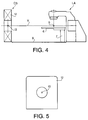
- Reference numeral 13 designates a center of the CT image which is center of the CT scanner as shown in Figs. 4 and 5.
- the base 7 of the couch 6 can be moved on the rail 8 to be positioned in the CT scanner CS.
- the center 13 is located on the same coordinate axis Y as the isocenter 5 of the linear accelerator LA and is adapted to be marked on each image of CT slices.
- the center 13 serves as a virtual isocenter for the CT scanning. As described hereinafter, the mark of the center on the CT image is moved as the motion of the isocenter 5 relative to the lesion, during the irradiation with the linear accelerator.
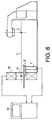
- the base 7 of the couch 6 is clamped to the gantry 12 of the CT scanner, so that the positional relation between the virtual isocenter 13 and the base 7 may exactly coincide with the positional relation between the isocenter 5 and the base 7 at the treatment by the X-rays.
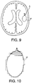
- Fig. 7 shows a CRT screen 14 in which the reference letter A designates a center position corresponding to the virtual isocenter 13 and BT shows an image of a brain tumor at one of the slices.
- Image data of each slice of CT scanning are read and stored in image memories like a conventional CT scanner.
- control data for the servomechanisms are also stored in control memories as described hereinafter.
- the control data are generated on the CRT screen 14.
- a mark in the form of a plus at the center position A is temporarily located at the position.
- the plus mark can be moved from the position A to a position B in the X-Z plane by moving a tip of a light pen 15 on the screen from A to B.
- the increments ⁇ X and ⁇ Z of the movement of the mark from A to B are read and stored in X and Z control memories respectively.
- the incremental data ⁇ X and ⁇ Z are used to control the couch 6 relative to the isocenter 5 at the treatment with the linear accelerator.
- the control system has a memory 16 for controlling the servomechanisms of the couch.
- the memory 16 comprises an X control memory 16a, a Z control memory 16b, a slice number memory 16c and a Y indexing memory 16d.
- the X control memory 16a is operatively connected to an X servomechanism 7a in the base 7 to feed the couch 6 in the X direction.
- the Z control memory 16b is connected to a Z servomechanism 7b.
- the Y indexing memory 16d is connected to a Y servomechanism 7c to index the couch 6 in the Y direction by an increment ⁇ Y.
- the base 7 is clamped to the gantry 12 of the CT scanner, until the end of CT scanning.
- the longitudinal axis of the base 7 along with the Y direction of the couch 6 is perpendicular to the plane of CT image 14.
- a scout view like conventional radiography, is taken by feeding the couch in the Y direction.
- the position of the lesion is identified and the three coordinates X0, Y0 and Z0 of an extreme end point P0 of the lesion, which corresponds to the position B of a first slice, are decided and memorized in the memories 16a, 16b, 16c and 16d by inspecting the scout view along with precise information of CT or MR image and so on, which were obtained at another diagnosis division.
- the CT slices are taken as usual by starting from the coordinate Y0 and by moving the couch 6 in the Y direction with an interval ⁇ Y0.
- the magnitude of interval ⁇ Y0 is determined by taking the equivalent diameter of the radio-spot into consideration, and all ⁇ Y0 feeds are memorized in the Y indexing memory 16d together with other Y movements of the couch.
- the Y coordinate of the couch is reset to the initial coordinate Y0.
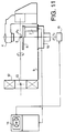
- the base 7 is unclamped from the gantry 12 and moved on the rail 8 to the position on the turntable 10 as shown in Fig. 11.
- the distance of this horizontal movement of the base 7 on the rail must be equal to that between the isocenter 5 and the center 13 of CT image plane. The latter distance is physically determined at the initial installation of the linear accelerator and the CT scanner.
- the plus mark of the virtual isocenter is at the position A. Then the mark is shifted to the position B corresponding to an upper extreme point of the tumor by operating the light pen. Thereafter, a physician makes a decision of the region of interest to irradiate. The region is encircled with the light pen, so that a contour line 17 is imaged on the screen.
- the screen is divided into a plurality of positions. Then, pushing a switch button initiates an automatic zigzag scanning motion of the mark within the encircled region on the X-Z plane as shown in Figs. 8 and 10.
- the interval of the zigzag motion is determined by taking the equivalent diameter of the radio-spot into consideration.
- the increments ⁇ X and ⁇ Z of all movements of the mark, such as the movement from A to B and the zigzag motion are stored in the X and Z memories 16a, 16b respectively. Namely, the coordinates of the positions on the contour line 17 are stored in the X, Z memories 16a, 16b and all positions in the contour are also stored in the memories.
- the memorizing operation is performed on all slices.
- the treatment with the radio-spot is started from the point P0.
- the actual point P0 (Fig. 11) is automatically coincided with the isocenter 5 by controlling the X and Z servomechanisms 7a and 7b in accordance with the data stored in the memories 16a and 16b at the initial inspection of P0.
- the Y axis control is started from Y0 of the extreme end point P0.
- the interval ⁇ Y0 at the treatment is determined to be equal to that in the CT scanning.
- the base 7 and the couch 6 are slowly rotated about the vertical axis in accordance with the turntable control with a controller 18 in Fig. 11 so as to make half revolution per treatment.
- the X-ray head 4 in Fig. 11 is continuously and reciprocatively rotated.
- the X and Z servomechanisms 7a and 7b control the relative motion of the radio-spot in each slice.
- the radio-spot is actually fixed at the isocenter 5 of linear accelerator, therefore the couch 6 is moved in the X-Z plane relative to the base 7 so as to make the radio-spot cover the whole encircled region.
- the present invention provides a system which may exactly irradiate X-rays to an affected part and minimize the dose of X-rays to other parts than the lesion.
Abstract
Description
- The present invention relates to a system for stereotactic radiotherapy using a computerized tomographic scanning system as an on-line controller, and more particularly to a system for a stereotactic radiation therapy with a linear accelerator which is operated in accordance with information obtained by the computerized tomographic scanning system.
- Referring to Figs. 1 and 2 showing a conventional linear accelerator LA, a rotating
frame 2 having anX-ray head 4 is rotatably mounted on abase 9 so as to be rotated about horizontal axis 1. TheX-ray head 4 is provided such that anaxis 3 of X-ray beams intersects the axis 1 at anisocenter 5. Consequently, reciprocative rotation of the rotatingframe 2 causes the X-rays to always pass theisocenter 5, which means that the X-rays concentrate to theisocenter 5. Therefore, an affected part of a patient is effectively treated. - However, in the conventional system, since the X-rays reciprocate in the same plane, other healthy parts in the plane may be affected by the radiation.
- On the other hand, the position of the lesion is determined by the eye-measurement of the operator in accordance with CT (Computed Tomography) scan data or data obtained by MRI (Magnetic Resonance Imaging) which were obtained at another place before the treatment. Therefore, the X-rays controlled by the eye-measurement not always are irradiated to the lesion.
- Accordingly, an object of the present invention is to provide a system which may exactly irradiate X-rays to an affected part.
- Another object of the present invention is to minimize the dose of X-rays to other parts than the lesion.
- According to the present invention, there is provided a system for stereotactic radiotherapy comprising a first apparatus having a head for emanating an ionizing radiation, the head being provided to be rotated about a horizontal axis, and such that the ionizing radiation intersects the horizontal axis at an isocenter, a second apparatus for taking a tomographic image, which is installed on the same floor as the first apparatus and has a center for the tomographic image, a base movable between the first and second apparatuses, a treatment couch horizontally movably mounted on the base, feeding means for feeding the couch with respect to the base to a longitudinal direction (Y) of the base and for feeding the couch within a vertical (X-Z) plane perpendicular to the direction (Y), positioning means for positioning the base in the second apparatus so that the positional relation between the center and the base coincides with the positional relation between the isocenter and the base, storing means for storing data on a particular position in the tomographic image, control means for controlling the feeding means so that the ionizing radiation is irradiated to a part in a patient on the couch dependent on the stored data of the position.
- In an aspect of the invention, the first apparatus is a linear accelerator having an X-ray head and the second apparatus is a CT scanner.
- In the system of the present invention, the CT scanner is placed opposite to the linear accelerator, and the treatment couch is used for both of the CT scanning and the radiation therapy by the linear accelerator. Immediately after the CT scanning, the treatment couch is moved onto a turntable beneath the X-ray head of the linear accelerator. The treatment is proceeded at the isocenter of the linear accelerator, while the turntable is continuously rotated about a vertical axis.
- A beam of X-rays is collimated as slender as possible (about 5 mm in diameter). The beam passes through the isocenter during the continuous and reciprocative rotation of the X-ray head about a horizontal axis. On the other hand, the base and the treatment couch on the turntable is slowly rotated (half revolution per treatment) around the vertical axis passing through the isocenter. Thus, the slender X-ray beam is focused at the isocenter, whereas the path of the beam passes through the body of the patient only one time. As a result, the dose of X-rays to tissues outside the lesion can be reduced to a minimal amount. Thus, the X-ray beam forms a "radio-spot" at the isocenter.
- For the treatment, the whole region of the lesion must be scanned by the radio-spot. For this purpose, the couch is moved with respect to a base thereof by servomechanisms. The servomechanisms are controlled by signals obtained by the CT scanner. To realize the production of precise CT data and exact irradiation of X-rays, matter of vital importance is to keep the lesion immobile to the treatment couch, during the time from the beginning of CT scanning to the end of treatment.
- In the treatment, the center of the image plane of CT scanning must accurately correspond to the isocenter of the linear accelerator. Therefore, the mechanical alignment of the base, to the CT scanner and to the turntable of linear accelerator is ensured in the system.
- The present invention is described in detail with reference to the accompanying drawings.
-
- Fig. 1 shows a side view of a conventional linear accelerator;
- Fig. 2 is a front view of the linear accelerator;
- Fig. 3 is a side view of a linear accelerator used in the system of the present invention;
- Fig. 4 is a side view of the system of the present invention;
- Fig. 5 is a front view of a CT scanner in Fig. 4;
- Fig. 6 is a side view of the system at CT scanning;
- Fig. 7 shows a CRT screen;
- Fig. 8 is a schematic diagram showing a control system;
- Fig. 9 illustrates a CT image on the CRT screen showing a brain tumor;
- Fig. 10 is an enlarged view of the tumor in Fig. 9; and
- Fig. 11 is a side view of the system at the treatment.
- Referring to Fig. 3, a
treatment couch 6 is mounted on abase 7. Thebase 7 is movably mounted on arail 11 on aturntable 10 and clamped to the turntable. Theturntable 10 is provided to be rotated about a vertical axis passing theisocenter 5. Acontroller 18 is provided for controlling the rotation of the turntable. Thecouch 6 is moved by servomechanisms equipped in thebase 7 which will be described hereinafter. The Y direction of motion of thecouch 6 coincides with the longitudinal axis of thebase 7. The Z direction is vertical. - Referring to Fig. 4, a CT scanner CS having a
gantry 12 is provided opposite to the linear accelerator LA. Arail 8 is installed between the linear accelerator LA and the CT scanner CS.Reference numeral 13 designates a center of the CT image which is center of the CT scanner as shown in Figs. 4 and 5. Thebase 7 of thecouch 6 can be moved on therail 8 to be positioned in the CT scanner CS. - The
center 13 is located on the same coordinate axis Y as theisocenter 5 of the linear accelerator LA and is adapted to be marked on each image of CT slices. Thecenter 13 serves as a virtual isocenter for the CT scanning. As described hereinafter, the mark of the center on the CT image is moved as the motion of theisocenter 5 relative to the lesion, during the irradiation with the linear accelerator. - Referring to Fig. 6, the
base 7 of thecouch 6 is clamped to thegantry 12 of the CT scanner, so that the positional relation between thevirtual isocenter 13 and thebase 7 may exactly coincide with the positional relation between theisocenter 5 and thebase 7 at the treatment by the X-rays. - Fig. 7 shows a
CRT screen 14 in which the reference letter A designates a center position corresponding to thevirtual isocenter 13 and BT shows an image of a brain tumor at one of the slices. Image data of each slice of CT scanning are read and stored in image memories like a conventional CT scanner. In addition to the image data, control data for the servomechanisms are also stored in control memories as described hereinafter. - The control data are generated on the
CRT screen 14. A mark in the form of a plus at the center position A is temporarily located at the position. The plus mark can be moved from the position A to a position B in the X-Z plane by moving a tip of alight pen 15 on the screen from A to B. The increments ΔX and ΔZ of the movement of the mark from A to B are read and stored in X and Z control memories respectively. The incremental data ΔX and ΔZ are used to control thecouch 6 relative to theisocenter 5 at the treatment with the linear accelerator. - Referring to Fig. 8, the control system has a
memory 16 for controlling the servomechanisms of the couch. Thememory 16 comprises anX control memory 16a, aZ control memory 16b, aslice number memory 16c and aY indexing memory 16d. TheX control memory 16a is operatively connected to anX servomechanism 7a in thebase 7 to feed thecouch 6 in the X direction. Similarly, theZ control memory 16b is connected to aZ servomechanism 7b. TheY indexing memory 16d is connected to aY servomechanism 7c to index thecouch 6 in the Y direction by an increment ΔY. - In operation, the
base 7 is clamped to thegantry 12 of the CT scanner, until the end of CT scanning. The longitudinal axis of thebase 7 along with the Y direction of thecouch 6 is perpendicular to the plane ofCT image 14. At first, a scout view, like conventional radiography, is taken by feeding the couch in the Y direction. Then the position of the lesion is identified and the three coordinates X₀, Y₀ and Z₀ of an extreme end point P₀ of the lesion, which corresponds to the position B of a first slice, are decided and memorized in thememories - The CT slices are taken as usual by starting from the coordinate Y₀ and by moving the
couch 6 in the Y direction with an interval ΔY₀. The magnitude of interval ΔY₀ is determined by taking the equivalent diameter of the radio-spot into consideration, and all ΔY₀ feeds are memorized in theY indexing memory 16d together with other Y movements of the couch. After the CT scanning is finished, the Y coordinate of the couch is reset to the initial coordinate Y₀. - Thereafter, the
base 7 is unclamped from thegantry 12 and moved on therail 8 to the position on theturntable 10 as shown in Fig. 11. The distance of this horizontal movement of thebase 7 on the rail must be equal to that between theisocenter 5 and thecenter 13 of CT image plane. The latter distance is physically determined at the initial installation of the linear accelerator and the CT scanner. - Referring to Fig. 9 showing one of the slices, the plus mark of the virtual isocenter is at the position A. Then the mark is shifted to the position B corresponding to an upper extreme point of the tumor by operating the light pen. Thereafter, a physician makes a decision of the region of interest to irradiate. The region is encircled with the light pen, so that a
contour line 17 is imaged on the screen. - The screen is divided into a plurality of positions. Then, pushing a switch button initiates an automatic zigzag scanning motion of the mark within the encircled region on the X-Z plane as shown in Figs. 8 and 10. The interval of the zigzag motion is determined by taking the equivalent diameter of the radio-spot into consideration. At the same time, the increments ΔX and ΔZ of all movements of the mark, such as the movement from A to B and the zigzag motion are stored in the X and
Z memories contour line 17 are stored in the X,Z memories - The treatment with the radio-spot is started from the point P₀. The actual point P₀ (Fig. 11) is automatically coincided with the
isocenter 5 by controlling the X andZ servomechanisms memories base 7 and thecouch 6 are slowly rotated about the vertical axis in accordance with the turntable control with acontroller 18 in Fig. 11 so as to make half revolution per treatment. TheX-ray head 4 in Fig. 11 is continuously and reciprocatively rotated. - The X and
Z servomechanisms isocenter 5 of linear accelerator, therefore thecouch 6 is moved in the X-Z plane relative to thebase 7 so as to make the radio-spot cover the whole encircled region. - From the foregoing, it will be understood that the present invention provides a system which may exactly irradiate X-rays to an affected part and minimize the dose of X-rays to other parts than the lesion.
- While the invention has been described in conjunction with preferred specific embodiment thereof, it will be understood that this description is intended to illustrate and not limit the scope of the invention, which is defined by the following claims.
Claims (7)
- System for stereotactic radiotherapy comprising:
a first apparatus having a head for emanating an ionizing radiation, said head being provided to be rotated about a horizontal axis, and such that the ionizing radiation intersects said horizontal axis at an isocenter;
a second apparatus for taking a tomographic image, which is installed on the same floor as the first apparatus and has a center for said tomographic image;
a base movable between said first and second apparatuses;
a treatment couch horizontally movably mounted on said base;
feeding means for feeding said couch with respect to said base to a longitudinal direction (Y) of said base and for feeding said couch within a vertical (X-Z) plane perpendicular to said direction (Y);
positioning means for positioning said base in said second apparatus so that the positional relation between said center and said base coincides with the positional relation between said isocenter and the base;
storing means for storing data on a particular position in said tomographic image;
control means for controlling said feeding means so that said ionizing radiation is irradiated to a part in a patient on said couch dependent on said stored data of the position. - A system for stereotactic radiotherapy according to claim 1 wherein the first apparatus is a linear accelerator having an X-ray head.
- A system for stereotactic radiotherapy according to claim 2 wherein the second apparatus is a CT scanner.
- A system for stereotactic radiotherapy according to claim 1 further comprising a turntable provided to be rotated about a vertical axis passing through said isocenter, and for securely mounting said base.
- A system for stereotactic radiotherapy according to claim 1 wherein said feeding means comprises three servomechanisms for moving said couch in said longitudinal direction (Y) and within said vertical plane (X-Z).
- A system for stereotactic radiotherapy according to claim 3 wherein said feeding means is provided for intermittently feeding said couch in said longitudinal direction with a regular interval for producing a plurality of CT slices.
- A system for stereotactic radiotherapy according to claim 6 further comprising means for moving a mark on a CT image, and first storing means for storing a position of a trace of the movement of the mark, second storing means for storing a position of said couch with respect to said base in said longitudinal direction at every CT slice, and said control means being provided for moving said couch in said linear accelerator in accordance with the stored positions by said first and second storing means.
Applications Claiming Priority (2)
| Application Number | Priority Date | Filing Date | Title |
|---|---|---|---|
| JP115116/92 | 1992-03-24 | ||
| JP4115116A JPH0779813B2 (en) | 1992-03-24 | 1992-03-24 | Radiation therapy equipment |
Publications (3)
| Publication Number | Publication Date |
|---|---|
| EP0562585A2 true EP0562585A2 (en) | 1993-09-29 |
| EP0562585A3 EP0562585A3 (en) | 1995-05-17 |
| EP0562585B1 EP0562585B1 (en) | 1998-07-22 |
Family
ID=14654645
Family Applications (1)
| Application Number | Title | Priority Date | Filing Date |
|---|---|---|---|
| EP93104897A Expired - Lifetime EP0562585B1 (en) | 1992-03-24 | 1993-03-24 | System for stereotactic radiotherapy with a computerized tomographic scanning system |
Country Status (4)
| Country | Link |
|---|---|
| US (1) | US5329567A (en) |
| EP (1) | EP0562585B1 (en) |
| JP (1) | JPH0779813B2 (en) |
| DE (1) | DE69319769T2 (en) |
Cited By (22)
| Publication number | Priority date | Publication date | Assignee | Title |
|---|---|---|---|---|
| DE4341289A1 (en) * | 1993-12-03 | 1995-06-08 | Siemens Ag | Medical equipment for therapy and/or diagnosis |
| DE4341290A1 (en) * | 1993-12-03 | 1995-06-08 | Siemens Ag | Medical equipment for therapy and/or diagnosis |
| WO1995033519A1 (en) * | 1994-06-09 | 1995-12-14 | Elekta Instrument Ab | Positioning device and method for radiation treatment |
| WO1996002299A1 (en) * | 1994-07-18 | 1996-02-01 | Centre Claudius Regaud | Method for indexing the position of a portion of the human body prior to an operation on a target area of interest |
| EP0700578A1 (en) * | 1993-03-30 | 1996-03-13 | Intraop Medical, Inc. | Intraoperative electron beam therapy system and facility |
| EP0712606A1 (en) * | 1994-11-21 | 1996-05-22 | Picker International, Inc. | Medical diagnostic imaging systems and methods |
| FR2728471A1 (en) * | 1994-12-27 | 1996-06-28 | Ge Medical Syst Sa | Radiotherapy appts. for three dimensional imaging and treatment |
| EP0757255A2 (en) * | 1995-07-27 | 1997-02-05 | Gec-Marconi Limited | Imaging systems |
| US5835556A (en) * | 1995-05-23 | 1998-11-10 | Rogalla; Patrik | Process and device for computer tomography transillumination for treatment |
| GB2333217A (en) * | 1998-01-08 | 1999-07-14 | Elekta Ab | Radiotherapy device and treatment table having controlled motion with three degrees of freedom |
| WO2000030537A1 (en) * | 1998-11-20 | 2000-06-02 | Forschungszentrum Jülich GmbH | Tomograph with high local resolution |
| EP1238685A1 (en) * | 2001-03-05 | 2002-09-11 | BrainLAB AG | Patient positioning system for radiotherapy |
| EP1389479A1 (en) * | 2002-08-14 | 2004-02-18 | Minoru Uematsu | Composite system for radiation therapy |
| WO2004047923A1 (en) * | 2002-11-28 | 2004-06-10 | Elekta Ab (Publ) | Radiotherapy apparatus and operating method |
| EP1623739A2 (en) * | 2004-08-06 | 2006-02-08 | BrainLAB AG | Volumetric imaging in a radiation therapy device |
| WO2006095308A1 (en) * | 2005-03-09 | 2006-09-14 | Koninklijke Philips Electronics N.V. | A patient handling system whereby a patient table top can move over a table base |
| WO2007012649A1 (en) * | 2005-07-26 | 2007-02-01 | Siemens Aktiengesellschaft | Radiation therapy system and methods for planning a radiation therapy |
| EP1764040A2 (en) * | 2005-09-16 | 2007-03-21 | Siemens Aktiengesellschaft | Method for radiologic 3D imaging with reduced artefacts, medical imaging device and method of establishing a treatment plan |
| EP1785161A1 (en) * | 2005-11-11 | 2007-05-16 | Siemens Aktiengesellschaft | Treatment room of a particle therapy system, treatment plan, method of creating a treatment plan, and method of irradiation treatment |
| EP1972277A1 (en) * | 2007-03-20 | 2008-09-24 | Cefla Societa' Cooperativa | Method for positioning an object to be analysed for a computed tomography scanner |
| WO2009007737A1 (en) * | 2007-07-11 | 2009-01-15 | Elekta Ab (Publ) | Radiotherapy apparatus |
| EP2052759A1 (en) * | 2007-10-27 | 2009-04-29 | Werner Brenneisen | Radiation therapy device |
Families Citing this family (44)
| Publication number | Priority date | Publication date | Assignee | Title |
|---|---|---|---|---|
| US6331180B1 (en) | 1988-05-03 | 2001-12-18 | Sherwood Services Ag | Target-centered stereotaxtic surgical arc system with reorientatable arc axis |
| DE4202302C2 (en) * | 1992-01-28 | 1999-06-10 | Dietrich H W Prof Groenemeyer | Computer tomograph |
| DE4325212C2 (en) * | 1993-07-27 | 1996-04-11 | Siemens Ag | Medical device |
| EP0673661B1 (en) * | 1994-03-25 | 2003-03-12 | Kabushiki Kaisha Toshiba | Radiotherapy system |
| US5537452A (en) * | 1994-05-10 | 1996-07-16 | Shepherd; Joseph S. | Radiation therapy and radiation surgery treatment system and methods of use of same |
| JPH0857069A (en) * | 1994-08-22 | 1996-03-05 | Toshiba Corp | Radiotherapeutic device |
| DE19530013C1 (en) * | 1995-08-16 | 1997-03-06 | Werner Dipl Phys Brenneisen | Correcting position of target e.g. tumour in target region of radiation treatment device |
| US5661772A (en) * | 1996-04-01 | 1997-08-26 | Siemens Aktiengesellschaft | X-ray diagnostics apparatus capable of producing CT images and fluoroscopic images |
| DE19650013A1 (en) * | 1996-12-03 | 1998-06-04 | Juergen Dipl Ing Naegeler | Tissue irradiation arrangement for tumour treatment |
| JP4354550B2 (en) * | 1998-08-31 | 2009-10-28 | 株式会社島津製作所 | Radiation therapy planning device |
| DE19853463B4 (en) * | 1998-11-19 | 2005-08-11 | Siemens Ag | Multiple examination arrangement with a variety of imaging systems |
| DE10010523C2 (en) * | 2000-03-07 | 2002-08-14 | Schwerionenforsch Gmbh | Ion beam system for the irradiation of tumor tissue |
| JP3639183B2 (en) * | 2000-04-25 | 2005-04-20 | ジーイー・メディカル・システムズ・グローバル・テクノロジー・カンパニー・エルエルシー | Radiation therapy equipment |
| US20030090765A1 (en) * | 2001-11-09 | 2003-05-15 | Neff Brian W. | Free-space optical communication system |
| US7346144B2 (en) * | 2002-03-14 | 2008-03-18 | Siemens Medical Solutions Usa, Inc. | In vivo planning and treatment of cancer therapy |
| JP3953997B2 (en) * | 2003-09-26 | 2007-08-08 | ジーイー・メディカル・システムズ・グローバル・テクノロジー・カンパニー・エルエルシー | Angio CT system |
| US7170968B2 (en) * | 2003-10-22 | 2007-01-30 | Xoran Technologies, Inc. | CT scanner system and method for improved positioning |
| US7366336B2 (en) * | 2004-03-09 | 2008-04-29 | Siemens Medical Solutions Usa, Inc. | System to link periodic X-ray images |
| US7388976B2 (en) * | 2004-03-09 | 2008-06-17 | Siemens Medical Solutions Usa, Inc. | Time-based system to link periodic X-ray images |
| EP1709994A1 (en) * | 2005-04-04 | 2006-10-11 | Ion Beam Applications S.A. | Patient positioning imaging device and method |
| US20070003010A1 (en) | 2005-04-29 | 2007-01-04 | Varian Medical Systems Technologies, Inc. | Radiation systems with imaging capability |
| JP4936924B2 (en) * | 2007-02-20 | 2012-05-23 | 稔 植松 | Particle beam irradiation system |
| US8017915B2 (en) | 2008-03-14 | 2011-09-13 | Reflexion Medical, Inc. | Method and apparatus for emission guided radiation therapy |
| US8550711B2 (en) | 2008-06-18 | 2013-10-08 | Mitsubishi Electric Corporation | Treatment table system |
| CN103650095B (en) | 2011-03-31 | 2016-12-07 | 反射医疗公司 | For the system and method used in launching the radiotherapy guided |
| CN102323279B (en) * | 2011-06-17 | 2013-01-09 | 东南大学 | X-ray tomography-based in-situ loading device |
| WO2013134623A1 (en) | 2012-03-08 | 2013-09-12 | Neutar, Llc | Patient and procedure customized fixation and targeting devices for stereotactic frames |
| CN104161532A (en) * | 2013-05-15 | 2014-11-26 | 上海联影医疗科技有限公司 | Radiotherapy equipment |
| CN203634188U (en) * | 2013-11-14 | 2014-06-11 | 上海联影医疗科技有限公司 | Radioactive medical device |
| JP6850482B2 (en) | 2015-06-10 | 2021-03-31 | リフレクション メディカル, インコーポレイテッド | High bandwidth binary multi-leaf collimator design |
| JP6869479B2 (en) * | 2015-11-02 | 2021-05-12 | 東芝エネルギーシステムズ株式会社 | Particle beam irradiation device and particle beam display program |
| EP3426345B1 (en) | 2016-03-09 | 2021-06-23 | RefleXion Medical, Inc. | Fluence map generation methods for radiotherapy |
| US10806409B2 (en) | 2016-09-23 | 2020-10-20 | Varian Medical Systems International Ag | Medical systems with patient supports |
| WO2018093849A1 (en) | 2016-11-15 | 2018-05-24 | Reflexion Medical, Inc. | Methods for radiation delivery in emission-guided radiotherapy |
| EP3541287A4 (en) | 2016-11-15 | 2020-09-30 | RefleXion Medical, Inc. | Radiation therapy patient platform |
| WO2018093933A1 (en) | 2016-11-15 | 2018-05-24 | Reflexion Medical, Inc. | System for emission-guided high-energy photon delivery |
| WO2018183748A1 (en) | 2017-03-30 | 2018-10-04 | Reflexion Medical, Inc. | Radiation therapy systems and methods with tumor tracking |
| EP3651851B1 (en) | 2017-07-11 | 2023-11-08 | RefleXion Medical, Inc. | Methods for pet detector afterglow management |
| EP3664712A4 (en) | 2017-08-09 | 2021-05-05 | RefleXion Medical, Inc. | Systems and methods for fault detection in emission-guided radiotherapy |
| US11369806B2 (en) | 2017-11-14 | 2022-06-28 | Reflexion Medical, Inc. | Systems and methods for patient monitoring for radiotherapy |
| US11024084B2 (en) | 2018-02-08 | 2021-06-01 | Varian Medical Systems International Ag | Systems and methods for providing medical information and for performing a medically-related process using augmented reality technology |
| US10825251B2 (en) * | 2018-02-08 | 2020-11-03 | Varian Medical Systems International Ag | Systems and methods for providing medical information and for performing a medically-related process using augmented reality technology |
| US11666241B2 (en) * | 2019-02-02 | 2023-06-06 | Shanghai United Imaging Healthcare Co., Ltd. | System and method for medical imaging |
| CN114053598A (en) * | 2020-08-06 | 2022-02-18 | 西安大医集团股份有限公司 | Virtual isocenter calibration method, laser lamp calibration method and radiotherapy system |
Citations (3)
| Publication number | Priority date | Publication date | Assignee | Title |
|---|---|---|---|---|
| FR2115423A1 (en) * | 1970-11-27 | 1972-07-07 | Varian Associates | |
| DE3828639A1 (en) * | 1987-08-24 | 1989-03-16 | Mitsubishi Electric Corp | Ionised particle beam therapy device |
| WO1990011721A1 (en) * | 1989-03-31 | 1990-10-18 | Loma Linda University Medical Center | Patient alignment system and procedure for radiation treatment |
Family Cites Families (2)
| Publication number | Priority date | Publication date | Assignee | Title |
|---|---|---|---|---|
| JP2931983B2 (en) * | 1989-06-30 | 1999-08-09 | ジーイー横河メディカルシステム株式会社 | Radiation therapy system |
| US5199060A (en) * | 1990-06-04 | 1993-03-30 | Kabushiki Kaisha Toshiba | X-ray photographing apparatus |
-
1992
- 1992-03-24 JP JP4115116A patent/JPH0779813B2/en not_active Expired - Lifetime
-
1993
- 1993-03-22 US US08/035,037 patent/US5329567A/en not_active Expired - Fee Related
- 1993-03-24 DE DE69319769T patent/DE69319769T2/en not_active Expired - Fee Related
- 1993-03-24 EP EP93104897A patent/EP0562585B1/en not_active Expired - Lifetime
Patent Citations (3)
| Publication number | Priority date | Publication date | Assignee | Title |
|---|---|---|---|---|
| FR2115423A1 (en) * | 1970-11-27 | 1972-07-07 | Varian Associates | |
| DE3828639A1 (en) * | 1987-08-24 | 1989-03-16 | Mitsubishi Electric Corp | Ionised particle beam therapy device |
| WO1990011721A1 (en) * | 1989-03-31 | 1990-10-18 | Loma Linda University Medical Center | Patient alignment system and procedure for radiation treatment |
Cited By (40)
| Publication number | Priority date | Publication date | Assignee | Title |
|---|---|---|---|---|
| EP0700578A1 (en) * | 1993-03-30 | 1996-03-13 | Intraop Medical, Inc. | Intraoperative electron beam therapy system and facility |
| EP0700578A4 (en) * | 1993-03-30 | 1997-01-15 | Intraop Inc | Intraoperative electron beam therapy system and facility |
| DE4341289A1 (en) * | 1993-12-03 | 1995-06-08 | Siemens Ag | Medical equipment for therapy and/or diagnosis |
| DE4341290A1 (en) * | 1993-12-03 | 1995-06-08 | Siemens Ag | Medical equipment for therapy and/or diagnosis |
| WO1995033519A1 (en) * | 1994-06-09 | 1995-12-14 | Elekta Instrument Ab | Positioning device and method for radiation treatment |
| WO1996002299A1 (en) * | 1994-07-18 | 1996-02-01 | Centre Claudius Regaud | Method for indexing the position of a portion of the human body prior to an operation on a target area of interest |
| EP0712606A1 (en) * | 1994-11-21 | 1996-05-22 | Picker International, Inc. | Medical diagnostic imaging systems and methods |
| FR2728471A1 (en) * | 1994-12-27 | 1996-06-28 | Ge Medical Syst Sa | Radiotherapy appts. for three dimensional imaging and treatment |
| US5835556A (en) * | 1995-05-23 | 1998-11-10 | Rogalla; Patrik | Process and device for computer tomography transillumination for treatment |
| EP0757255A2 (en) * | 1995-07-27 | 1997-02-05 | Gec-Marconi Limited | Imaging systems |
| EP0757255A3 (en) * | 1995-07-27 | 1997-04-16 | Marconi Gec Ltd | Imaging systems |
| US5823960A (en) * | 1995-07-27 | 1998-10-20 | Picker International, Inc. | Imaging systems |
| GB2333217A (en) * | 1998-01-08 | 1999-07-14 | Elekta Ab | Radiotherapy device and treatment table having controlled motion with three degrees of freedom |
| US6307876B1 (en) | 1998-01-08 | 2001-10-23 | Elekta Ab | Linear accelerator |
| WO2000030537A1 (en) * | 1998-11-20 | 2000-06-02 | Forschungszentrum Jülich GmbH | Tomograph with high local resolution |
| EP1238685A1 (en) * | 2001-03-05 | 2002-09-11 | BrainLAB AG | Patient positioning system for radiotherapy |
| EP1384494A1 (en) * | 2001-03-05 | 2004-01-28 | BrainLAB AG | Patient positioning system for radiotherapy |
| US6865411B2 (en) | 2001-03-05 | 2005-03-08 | Brainlab Ag | Patient positioning system for radiotherapy |
| USRE47588E1 (en) | 2001-03-05 | 2019-09-03 | Brainlab Ag | Patient positioning system for radiotherapy |
| US8789223B2 (en) | 2001-03-05 | 2014-07-29 | Brainlab Ag | Patient positioning system for radiotherapy |
| US7818838B2 (en) | 2001-03-05 | 2010-10-26 | Brainlab Ag | Patient positioning system for radiotherapy |
| EP1389479A1 (en) * | 2002-08-14 | 2004-02-18 | Minoru Uematsu | Composite system for radiation therapy |
| US7603164B2 (en) | 2002-08-14 | 2009-10-13 | Minoru Uematsu | Composite system for radiation therapy |
| WO2004047923A1 (en) * | 2002-11-28 | 2004-06-10 | Elekta Ab (Publ) | Radiotherapy apparatus and operating method |
| EP1623739A2 (en) * | 2004-08-06 | 2006-02-08 | BrainLAB AG | Volumetric imaging in a radiation therapy device |
| EP1623738A1 (en) * | 2004-08-06 | 2006-02-08 | BrainLAB AG | Volumetric imaging in a radiation therapy device |
| EP1623739A3 (en) * | 2004-08-06 | 2006-04-26 | BrainLAB AG | Volumetric imaging in a radiation therapy device |
| US7324626B2 (en) | 2004-08-06 | 2008-01-29 | Brainlab Ag | Volumetric imaging on a radiotherapy apparatus |
| WO2006095308A1 (en) * | 2005-03-09 | 2006-09-14 | Koninklijke Philips Electronics N.V. | A patient handling system whereby a patient table top can move over a table base |
| US7810187B2 (en) | 2005-03-09 | 2010-10-12 | Koninklijke Philips Electronics N.V. | Patient handling system whereby a patient table top can move over a table base |
| CN101137328B (en) * | 2005-03-09 | 2010-06-23 | 皇家飞利浦电子股份有限公司 | A patient handling system whereby a patient table top can move over a table base |
| WO2007012649A1 (en) * | 2005-07-26 | 2007-02-01 | Siemens Aktiengesellschaft | Radiation therapy system and methods for planning a radiation therapy |
| EP1764040A3 (en) * | 2005-09-16 | 2007-05-23 | Siemens Aktiengesellschaft | Method for radiologic 3D imaging with reduced artefacts, medical imaging device and method of establishing a treatment plan |
| US7818045B2 (en) | 2005-09-16 | 2010-10-19 | Siemens Aktiengesellschaft | Method for reduced-artifact radiological 3D imaging, medical imaging device and method for creating a therapy plan |
| EP1764040A2 (en) * | 2005-09-16 | 2007-03-21 | Siemens Aktiengesellschaft | Method for radiologic 3D imaging with reduced artefacts, medical imaging device and method of establishing a treatment plan |
| WO2007054546A1 (en) * | 2005-11-11 | 2007-05-18 | Siemens Aktiengesellschaft | Treatment room of a particle therapy system, therapy plan, method for drawing up a therapy plan, irradiation method and particle therapy system |
| EP1785161A1 (en) * | 2005-11-11 | 2007-05-16 | Siemens Aktiengesellschaft | Treatment room of a particle therapy system, treatment plan, method of creating a treatment plan, and method of irradiation treatment |
| EP1972277A1 (en) * | 2007-03-20 | 2008-09-24 | Cefla Societa' Cooperativa | Method for positioning an object to be analysed for a computed tomography scanner |
| WO2009007737A1 (en) * | 2007-07-11 | 2009-01-15 | Elekta Ab (Publ) | Radiotherapy apparatus |
| EP2052759A1 (en) * | 2007-10-27 | 2009-04-29 | Werner Brenneisen | Radiation therapy device |
Also Published As
| Publication number | Publication date |
|---|---|
| JPH05309091A (en) | 1993-11-22 |
| US5329567A (en) | 1994-07-12 |
| JPH0779813B2 (en) | 1995-08-30 |
| DE69319769T2 (en) | 1998-11-26 |
| DE69319769D1 (en) | 1998-08-27 |
| EP0562585B1 (en) | 1998-07-22 |
| EP0562585A3 (en) | 1995-05-17 |
Similar Documents
| Publication | Publication Date | Title |
|---|---|---|
| US5329567A (en) | System for stereotactic radiotherapy with a computerized tomographic scanning system | |
| EP1389479B1 (en) | Composite system for radiation therapy | |
| EP0673661B1 (en) | Radiotherapy system | |
| EP1958663B1 (en) | Medical device | |
| US5740225A (en) | Radiation therapy planning method and its system and apparatus | |
| KR100314902B1 (en) | Method and Apparatus For Lesion Position Verification | |
| JP2000509291A (en) | Radiotherapy and radiosurgery systems and methods of use | |
| US5657368A (en) | Apparatus for positioning and marking a patient at a diagnostic apparatus | |
| US20090252290A1 (en) | In bore ct localization marking lasers | |
| US5675625A (en) | Apparatus for positioning and marking a patient at a diagnostic apparatus | |
| JP4064952B2 (en) | Radiotherapy apparatus and method of operating radiotherapy apparatus | |
| JPH119708A (en) | Radiotherapy device | |
| US5715820A (en) | X-ray bone densitometry using multiple pass scanning with image blending | |
| JP3961464B2 (en) | Radiotherapy compound device | |
| JP2004255160A5 (en) | ||
| JPH07255719A (en) | Ct system for radiation treatment plan, radiation treatment device and radiation treatment system | |
| JP3447362B2 (en) | Radiation treatment planning device | |
| JP4643544B2 (en) | Bed positioning system, radiation therapy system, and particle beam therapy system | |
| JPS5894835A (en) | Radioactive diagnostic and treating apparatus | |
| JP3625871B2 (en) | Medical device having radiation treatment planning function | |
| JPH08257149A (en) | Radiation treatment program apparatus | |
| JPH0751128B2 (en) | Radiation irradiation device | |
| JPH045143Y2 (en) | ||
| CN115054838A (en) | Radiotherapy reset automatic scanning simulation positioning system and control method | |
| JPH1176432A (en) | Radiotherapy device and method thereof |
Legal Events
| Date | Code | Title | Description |
|---|---|---|---|
| PUAI | Public reference made under article 153(3) epc to a published international application that has entered the european phase |
Free format text: ORIGINAL CODE: 0009012 |
|
| 17P | Request for examination filed |
Effective date: 19930324 |
|
| AK | Designated contracting states |
Kind code of ref document: A2 Designated state(s): DE FR GB NL |
|
| PUAL | Search report despatched |
Free format text: ORIGINAL CODE: 0009013 |
|
| AK | Designated contracting states |
Kind code of ref document: A3 Designated state(s): DE FR GB NL |
|
| GRAG | Despatch of communication of intention to grant |
Free format text: ORIGINAL CODE: EPIDOS AGRA |
|
| 17Q | First examination report despatched |
Effective date: 19970825 |
|
| GRAG | Despatch of communication of intention to grant |
Free format text: ORIGINAL CODE: EPIDOS AGRA |
|
| GRAH | Despatch of communication of intention to grant a patent |
Free format text: ORIGINAL CODE: EPIDOS IGRA |
|
| GRAH | Despatch of communication of intention to grant a patent |
Free format text: ORIGINAL CODE: EPIDOS IGRA |
|
| GRAA | (expected) grant |
Free format text: ORIGINAL CODE: 0009210 |
|
| AK | Designated contracting states |
Kind code of ref document: B1 Designated state(s): DE FR GB NL |
|
| PG25 | Lapsed in a contracting state [announced via postgrant information from national office to epo] |
Ref country code: NL Free format text: LAPSE BECAUSE OF FAILURE TO SUBMIT A TRANSLATION OF THE DESCRIPTION OR TO PAY THE FEE WITHIN THE PRESCRIBED TIME-LIMIT Effective date: 19980722 Ref country code: FR Free format text: LAPSE BECAUSE OF FAILURE TO SUBMIT A TRANSLATION OF THE DESCRIPTION OR TO PAY THE FEE WITHIN THE PRESCRIBED TIME-LIMIT Effective date: 19980722 |
|
| REF | Corresponds to: |
Ref document number: 69319769 Country of ref document: DE Date of ref document: 19980827 |
|
| EN | Fr: translation not filed | ||
| NLV1 | Nl: lapsed or annulled due to failure to fulfill the requirements of art. 29p and 29m of the patents act | ||
| PLBE | No opposition filed within time limit |
Free format text: ORIGINAL CODE: 0009261 |
|
| STAA | Information on the status of an ep patent application or granted ep patent |
Free format text: STATUS: NO OPPOSITION FILED WITHIN TIME LIMIT |
|
| 26N | No opposition filed | ||
| PGFP | Annual fee paid to national office [announced via postgrant information from national office to epo] |
Ref country code: GB Payment date: 20000320 Year of fee payment: 8 |
|
| PGFP | Annual fee paid to national office [announced via postgrant information from national office to epo] |
Ref country code: DE Payment date: 20000428 Year of fee payment: 8 |
|
| PG25 | Lapsed in a contracting state [announced via postgrant information from national office to epo] |
Ref country code: GB Free format text: LAPSE BECAUSE OF NON-PAYMENT OF DUE FEES Effective date: 20010324 |
|
| GBPC | Gb: european patent ceased through non-payment of renewal fee |
Effective date: 20010324 |
|
| PG25 | Lapsed in a contracting state [announced via postgrant information from national office to epo] |
Ref country code: DE Free format text: LAPSE BECAUSE OF NON-PAYMENT OF DUE FEES Effective date: 20020101 |