EP0560199B1 - Method and apparatus for coating glassware - Google Patents
Method and apparatus for coating glassware Download PDFInfo
- Publication number
- EP0560199B1 EP0560199B1 EP93103403A EP93103403A EP0560199B1 EP 0560199 B1 EP0560199 B1 EP 0560199B1 EP 93103403 A EP93103403 A EP 93103403A EP 93103403 A EP93103403 A EP 93103403A EP 0560199 B1 EP0560199 B1 EP 0560199B1
- Authority
- EP
- European Patent Office
- Prior art keywords
- coating
- coating material
- glassware
- containers
- particles
- Prior art date
- Legal status (The legal status is an assumption and is not a legal conclusion. Google has not performed a legal analysis and makes no representation as to the accuracy of the status listed.)
- Expired - Lifetime
Links
Images


Classifications
-
- C—CHEMISTRY; METALLURGY
- C03—GLASS; MINERAL OR SLAG WOOL
- C03C—CHEMICAL COMPOSITION OF GLASSES, GLAZES OR VITREOUS ENAMELS; SURFACE TREATMENT OF GLASS; SURFACE TREATMENT OF FIBRES OR FILAMENTS MADE FROM GLASS, MINERALS OR SLAGS; JOINING GLASS TO GLASS OR OTHER MATERIALS
- C03C17/00—Surface treatment of glass, not in the form of fibres or filaments, by coating
- C03C17/001—General methods for coating; Devices therefor
- C03C17/003—General methods for coating; Devices therefor for hollow ware, e.g. containers
- C03C17/005—Coating the outside
-
- B—PERFORMING OPERATIONS; TRANSPORTING
- B05—SPRAYING OR ATOMISING IN GENERAL; APPLYING FLUENT MATERIALS TO SURFACES, IN GENERAL
- B05B—SPRAYING APPARATUS; ATOMISING APPARATUS; NOZZLES
- B05B16/00—Spray booths
- B05B16/90—Spray booths comprising conveying means for moving objects or other work to be sprayed in and out of the booth, e.g. through the booth
- B05B16/95—Spray booths comprising conveying means for moving objects or other work to be sprayed in and out of the booth, e.g. through the booth the objects or other work to be sprayed lying on, or being held above the conveying means, i.e. not hanging from the conveying means
-
- B—PERFORMING OPERATIONS; TRANSPORTING
- B05—SPRAYING OR ATOMISING IN GENERAL; APPLYING FLUENT MATERIALS TO SURFACES, IN GENERAL
- B05B—SPRAYING APPARATUS; ATOMISING APPARATUS; NOZZLES
- B05B5/00—Electrostatic spraying apparatus; Spraying apparatus with means for charging the spray electrically; Apparatus for spraying liquids or other fluent materials by other electric means
- B05B5/025—Discharge apparatus, e.g. electrostatic spray guns
- B05B5/053—Arrangements for supplying power, e.g. charging power
- B05B5/0533—Electrodes specially adapted therefor; Arrangements of electrodes
-
- B—PERFORMING OPERATIONS; TRANSPORTING
- B05—SPRAYING OR ATOMISING IN GENERAL; APPLYING FLUENT MATERIALS TO SURFACES, IN GENERAL
- B05B—SPRAYING APPARATUS; ATOMISING APPARATUS; NOZZLES
- B05B5/00—Electrostatic spraying apparatus; Spraying apparatus with means for charging the spray electrically; Apparatus for spraying liquids or other fluent materials by other electric means
- B05B5/08—Plant for applying liquids or other fluent materials to objects
-
- B—PERFORMING OPERATIONS; TRANSPORTING
- B05—SPRAYING OR ATOMISING IN GENERAL; APPLYING FLUENT MATERIALS TO SURFACES, IN GENERAL
- B05B—SPRAYING APPARATUS; ATOMISING APPARATUS; NOZZLES
- B05B7/00—Spraying apparatus for discharge of liquids or other fluent materials from two or more sources, e.g. of liquid and air, of powder and gas
- B05B7/0012—Apparatus for achieving spraying before discharge from the apparatus
-
- C—CHEMISTRY; METALLURGY
- C03—GLASS; MINERAL OR SLAG WOOL
- C03C—CHEMICAL COMPOSITION OF GLASSES, GLAZES OR VITREOUS ENAMELS; SURFACE TREATMENT OF GLASS; SURFACE TREATMENT OF FIBRES OR FILAMENTS MADE FROM GLASS, MINERALS OR SLAGS; JOINING GLASS TO GLASS OR OTHER MATERIALS
- C03C17/00—Surface treatment of glass, not in the form of fibres or filaments, by coating
- C03C17/28—Surface treatment of glass, not in the form of fibres or filaments, by coating with organic material
- C03C17/32—Surface treatment of glass, not in the form of fibres or filaments, by coating with organic material with synthetic or natural resins
- C03C17/328—Polyolefins
-
- C—CHEMISTRY; METALLURGY
- C03—GLASS; MINERAL OR SLAG WOOL
- C03C—CHEMICAL COMPOSITION OF GLASSES, GLAZES OR VITREOUS ENAMELS; SURFACE TREATMENT OF GLASS; SURFACE TREATMENT OF FIBRES OR FILAMENTS MADE FROM GLASS, MINERALS OR SLAGS; JOINING GLASS TO GLASS OR OTHER MATERIALS
- C03C17/00—Surface treatment of glass, not in the form of fibres or filaments, by coating
- C03C17/34—Surface treatment of glass, not in the form of fibres or filaments, by coating with at least two coatings having different compositions
-
- B—PERFORMING OPERATIONS; TRANSPORTING
- B05—SPRAYING OR ATOMISING IN GENERAL; APPLYING FLUENT MATERIALS TO SURFACES, IN GENERAL
- B05B—SPRAYING APPARATUS; ATOMISING APPARATUS; NOZZLES
- B05B16/00—Spray booths
-
- B—PERFORMING OPERATIONS; TRANSPORTING
- B05—SPRAYING OR ATOMISING IN GENERAL; APPLYING FLUENT MATERIALS TO SURFACES, IN GENERAL
- B05B—SPRAYING APPARATUS; ATOMISING APPARATUS; NOZZLES
- B05B5/00—Electrostatic spraying apparatus; Spraying apparatus with means for charging the spray electrically; Apparatus for spraying liquids or other fluent materials by other electric means
- B05B5/08—Plant for applying liquids or other fluent materials to objects
- B05B5/082—Plant for applying liquids or other fluent materials to objects characterised by means for supporting, holding or conveying the objects
- B05B5/084—Plant for applying liquids or other fluent materials to objects characterised by means for supporting, holding or conveying the objects the objects lying on, or being supported above conveying means, e.g. conveyor belts
-
- C—CHEMISTRY; METALLURGY
- C03—GLASS; MINERAL OR SLAG WOOL
- C03C—CHEMICAL COMPOSITION OF GLASSES, GLAZES OR VITREOUS ENAMELS; SURFACE TREATMENT OF GLASS; SURFACE TREATMENT OF FIBRES OR FILAMENTS MADE FROM GLASS, MINERALS OR SLAGS; JOINING GLASS TO GLASS OR OTHER MATERIALS
- C03C2217/00—Coatings on glass
- C03C2217/40—Coatings comprising at least one inhomogeneous layer
- C03C2217/42—Coatings comprising at least one inhomogeneous layer consisting of particles only
Abstract
Description
- This invention relates to a method and apparatus for applying a lubricious transparent coating on glassware, and relates to a method and apparatus for applying coating material to the exterior of open top glass containers while precluding the deposition of coating material onto interior surfaces of the containers where it may affect the taste of the containers' contents. More particularly, this invention relates to method and apparatus for applying a new, inexpensive, thin, lubricious, transparent glassware coating that remains tenacious, lubricious and protective after exposure to high temperatures and sterilization and does not deleteriously affect the taste of such fragile container contents as beer or the labeling of the glassware.
- Formation of durable lubricious coatings have been found to be of great importance in the glass container industry to provide glass articles, or ware, with at least one layer of an adhering lubricating material in order to facilitate high speed automatic handling of glass articles in production lines and to protect articles against contact abrasion damage and unsightly scuff and scratch marks. Uncoated glass articles are highly susceptible to abrasion damage, and it has been reported that newly formed uncoated glass articles can quickly lose up to 75% of their bursting strength due, at least in part, to surface abrasion caused by contact with other glass articles, as normally occurs during processing and handling of such articles.
- While some coatings have been applied to articles just prior to use, to be fully effective, the articles must be coated soon after they are formed, and in the case of annealed articles, for example, such coatings have been applied immediately before and/or after annealing.
- In practice, pre-annealing coatings, sometimes referred to as "hot end" coatings, are applied to glassware after it leaves the glassware machine in an initial coater. The initial coater forms a very thin metal oxide coating on the outer surface on the surface of the glassware, which is then carried to the annealing lehr. Commonly used metal oxides include tin compounds and titanium oxide. Such pre-annealing coating methods and apparatus are disclosed, for example, in U.S. Patent Nos. 4,431,692; 4,615,916; 4,668,268; 4,719,126; and 4,719,127 and others listed below.
- A number of post-annealing coatings, sometimes referred to as "cold end" coatings, and methods and apparatus for their application, have been disclosed, for example, in U.S. Patent Nos. 2,995,633; 3,386,855; 3,487,035; 3,712,829; 3,801,361; 3,876,410; 3,989,004; 3,997,693; 4,039,310; 4,130,407; 4,135,014; 4,517,242; 4,517,243; 4,529,657; and 4,812,332.
- Electrostatic deposition methods and apparatus are well known. Such methods and apparatus have been in common use in industry to apply various useful, protective and decorative coatings. Examples of such electrostatic coating methods and apparatus include U.S. Patent Nos. 2,685,536; 2,794,417; 2,893,893; 2,893,894; Re. 24,602; 3,048,498; 3,169,882; 3,169,883; 3,323,934; 3,991,710; 4,073,966; 4,170,193 and many others. Notwithstanding their extensive development and use, electrostatic coating methods and apparatus have not been used in the application of cold end coating materials to glass containers.
- U.S. Patent Nos. 3,876,410 and 3,989,004 disclose the use of a coating material that is, at least in part, vaporizable at a readily obtainable temperature and capable of producing vapor that is contact-adherent to the article to be coated to produce a durable and tenacious, lubricious coating. In general, the patents disclose that an acceptable coating material can be formed from organic materials, particularly hydrocarbons formed from methylene, ethylene, propylene, butylene, fatty acids and their derivatives and the like, and that to be particularly effective, the vapor molecules of the coating material should be of a polar-non-polar nature such that the polar portion of the molecule will tend to adhere strongly to the article to be coated and oriented so that the non-polar portion of the molecule forms the lubricious external surface. A particularly useful group of such coating compositions disclosed in these patents are the saturated and unsaturated fatty acids containing between 10 and 18 carbon atoms. When used in the method of these patents, such coating materials are vaporized and conducted to the vicinity of newly formed glassware and readily adhere to the glassware in a thin, clear, tenacious, lubricious coating. To maintain the surface energy of the glassware at a high level, the glassware is maintained at a temperature between about 100° F. (37° C.) and 325° F. (162° C.) and preferably at a temperature between about 120° F. (49° C.) and 250° F. (121° C.).
- Caporic acid, stearic acid, oleic acid, myristic acid, linolic acid and palmatoleic acid [sic] are disclosed as typical of the compositions yielding desirable coatings on glassware when used according to the method of the above patents.
- Of the compositions disclosed in these patents, the preferred composition is oleic acid. Oleic acid is a bland liquid in normal condition having an appearance similar to that of cooking oil. It has been approved for use in connection with food products. As little as 1 drop of oleic acid every 17 seconds has been found sufficient to produce a superior lubricating coating on catsup bottles passing through the vapor at the rate of 80 bottles per minute. Thus, 1 drop of oleic acid provides sufficient vapor to coat about 20 catsup bottles. Further, oleic acid is readily available in high-grade quality at low cost. Because of these advantages, oleic acid has been a primary coating material used to provide post-annealing (cold end) coatings.
- Oleic acid, however, is liquid at temperatures in excess of 57° F (14° C.). When glassware coated with oleic acid is exposed to elevated temperatures, such as in an autoclave for the sterilization of food containers, the oleic acid coating is substantially removed by the harsh and hot conditions, and the scratch resistance and lubricity are deleteriously affected, thereby increasing the risk of breakage. Breakage during processing is serious because of the possibility of slivers or fragments of the shattered glass being deposited in adjacent ware, which is undesirable in most situations and is completely unacceptable when the ware is to be used for food packaging.
- It is also important that any coating material applied to glassware used with food or liquid products does not leave a residual taste of any sort in the food or liquid. Indeed, oleic acid is commonly known to impart a bad taste to the contents of the glassware, and is also known to adversely affect the foaming of carbonated beverages.
- Among the above-identified patents, U.S. Patent Nos. 4,039,310 and 4,130,407 disclose methods of strengthening glass against failure. U.S. Patent No. 4,039,310 discloses a method of strengthening glass by heating the glass to a temperature in excess of 700° F. (371° C.) but below the decomposition temperature of a selected fatty acid, such as behenic, stearic or glutamoric acid and applying the fatty acid to the heated glass. U.S. Patent No. 4,130,407 discloses a method of strengthening glass by applying a fatty acid derivative of an inorganic salt at temperatures between 100° C. (212° F.) and 500° C. (932° F.).
- With conventional coating methods, coating material is often needlessly applied to the interior of the glassware. Existing methods and apparatus for coating glassware do not preclude the deposition of coating material to the interior of the glassware. In many applications of glassware this presents no problem, even with such cold end coatings as oleic acid. However, a serious problem exists with respect to glass bottles used to contain beer, carbonated soft drinks and other fragile food stuffs whose taste, foaming or other characteristics may be damaged by glassware coating materials. Not only can an interior coating often taint the taste of beverages stored in the bottle, but such coatings, if applied to the exterior of the mouth of the bottle, can frequently leave a residual taste in the mouth of a person drinking directly from the bottle, which is common in the use of beer or soft drink bottles.
- A need exists in the manufacture of coated glass containers to coat the containers to provide an inexpensive, thin, tenacious and protective coating without affecting important desirable attributes of the containers' contents, such as taste, foaming and the like.
- This invention provides a new method and apparatus for providing glassware containers with a lubricious and protective coating that does not interfere with the taste and other desirable characteristics of beverages and other food stuff contents. Preferred coatings of the invention are also non-toxic and tenacious, retain their lubricity and protective qualities after exposure to the high temperatures and harsh conditions of sterilization, remain transparent, do not interfere with labeling and can reduce the cost and amount of hot end coating. This invention provides such coatings electrostatically substantially entirely onto the exterior of a container and can preclude the deposition of coating material onto the interior of the container and the exterior of the mouth of an open top container.
- Apparatus of the invention comprises means for providing a plurality of hot glass containers each having an open top, means forming a coating zone adapted to receive the glass containers to be coated, means for carrying the glass containers in an upright position through the coating chamber, means for generating an electrostatic charging and depositing field within the coating zone, and means for dispersing coating material particles within the coating zone for charging and deposition substantially entirely on the exterior surface of the glass containers.
- In the method of the invention, a plurality of glass containers is carried, while still hot, through a coating zone preferably by a grounded conveyor. An electrostatic charging and depositing field is generated in the coating zone that terminates substantially entirely on the exterior surface of the glass containers. Coating material in the form of a quiescent cloud of microu-size liquid particles is introduced into the coating zone and is electrostatically charged and deposited substantially entirely onto the exterior of the containers and generally below their open tops. In methods and apparatus of the invention, application of coating material is precluded from the glassware surface where it is unwanted by deposition substantially entirely by electrostatic forces.
- In preferred methods of the invention, the glass container coating is preferably stearic acid. The stearic acid coating material is liquified and preferably atomized into micron-sized particles using preferably a flow of gas, which can be an inert gas or air. The micron-sized stearic acid particles are introduced adjacent to hot glassware containers to be coated for deposition on the glassware surface. An electrostatic charging and depositing field is created in the coating zone, preferably by a high voltage electrode, which also charges the stearic acid particles. In the invention, the electrostatic depositing terminates substantially entirely on the external surface of the hot glassware container, which is maintained at a particle-attracting potential by a grounded support, or a metal mesh belt conveyor. With this invention any deposition of stearic acid coating material to the mouth and interior of the glassware containers is so small as to be undetectable and non-deleterious, even if the containers are used for beverages such as beer.
- Deposition of coating material can be further precluded from the mouth and neck of the glassware containers by cooling the top and/or neck region of the glassware containers prior to their entry into the coating zone. The hot portion of the glassware container is generally sufficiently electrically conductive to continue to attract the charged coating material particles as the containers pass through the charged coating material particles, but cooling the upper portion of the glassware container adjacent its open top decreases the electrical conductivity of the glassware in this portion to the point where the upper portion becomes insulative, i.e., sufficiently non-conductive to fail to attract the charged coating material particles in the coating zone.
- In the methods and apparatus of the invention a quiescent cloud of coating material particles is preferably generated by an atomizer coupled to the coating zone. The atomizer is connected to a liquid supply of heated coating material and employs a flow of atomizing gas to direct a gentle flow of fine coating material particles to the coating zone. The containers, heated to approximately 300° to 400° F. (149°-204° C.), are preferably carried through a coating chamber in a plurality of files, and the coating material particle cloud is introduced within the coating chamber at a plurality of dispersion points located between the files of containers and generally below the open tops of the containers. The electrostatic charging means, located preferably adjacent the points of dispersion of the coating material, charge the coating material particles for electrostatic deposition onto the exterior of the containers.
- The electrostatic charging means employed by this invention preferably includes a small plurality of separate needle electrodes separated by distance great enough to insure an ionizing electrostatic field gradient at their ends. Such electrodes can surround each dispersion orifice. In some preferred apparatus embodiments a single needle electrode can be disposed adjacent each dispersion orifice. In other embodiments, a plurality of wire electrodes can be arranged within the coating chamber separated by an effective electrostatic separation distance and oscillated in a cloud of fine coating material particles dispersed from stationary locations. In still other embodiments one or more wire electrodes may be located in the coating zone to establish an electrostatic charging and depositing field.
- Further features of this invention will be apparent from the following drawings and description of the invention.
-
- Fig. 1 is a single block diagram of a glassware manufacturing system with a dual coating application;
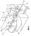
- Fig. 2 is a partially broken away perspective view of an embodiment of this invention;
- Fig. 3 is a cross-section, through one of the means for providing coating material particles, of the embodiment of Fig. 2 to further illustrate the invention;
- Fig. 4 is a diagrammatic representation of an electrostatic charging and depositing field to help explain the invention;
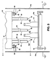
- Fig. 5 is a cross-sectional view of another embodiment of the invention;
- Fig. 6 is a cross-section at plane 6-6 of Fig. 5 through the means for providing charged coating material particles;
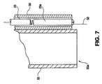
- Fig. 7 is a cross-sectional view through the center of one embodiment of an electrostatic charging means that may be used in the invention; and
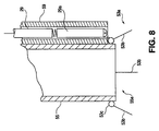
- Fig. 8 is a cross-sectional view through the center of another embodiment of an electrostatic charging means that may be used in the invention.
- Fig. 1 illustrates a
glassware manufacturing system 10 including a glassware forming machine 11 (such as an Individual Section (IS) Machine), an initial, or pre-annealing,coater 12, anannealing kiln 13 and afinal coater 14. Theglassware manufacturing system 10 forms a dual coating on the formed glassware with a pre-annealing, or "hot end" coating formed in theinitial coater 11 and a post-annealing, or "cold end" coating formed in thefinal coater 14. - When dual coatings are formed on glass articles, a metallic oxide coating is first formed on the surface of the articles, and this coating is preferably formed substantially immediately after the articles are formed and before the articles are annealed. This coating may be formed on the articles in a known manner and preferably is formed by exposing the articles to the vapor of a heat decomposable metallic compound while the articles are heated to a temperature above the decomposition point of the compound. Excellent results have been achieved by coating articles, substantially immediately after their forming, by means of the vapor of a tin compound and while the articles retain sufficient heat of formation to be still at a temperature above the decomposition point of the compound to thereby form a tin oxide coating on the surface of the article by chemical reaction between the vapor and the heated glass surface. In addition, titanium may be utilized, if desired, to form a titanium dioxide coating on the surface of the article in the same general manner.
- Suitable metallic compounds may be either organic or inorganic in nature, and may be, for example, an inorganic salt such as a metallic halide or an organic metallic compound such as alkyl aryl tin or ispopropyl titanate, etc. Tin compounds such as stannous chloride, stannic chloride, stannous fluoride, diethyl isobutyl tin, di-isopropyl tin dibromide, etc., have been found to be particularly useful in forming the tin oxide coating on the glass article. Titanium compounds such as titanium tetrachloride or tetra-isopropyl titanate likewise have been found to be particularly useful in forming a titanium dioxide coating on the glass article.
- The oxide coating formed on the articles is very thin and advantageously is less than about one-fourth wavelength of visible light in thickness. As a result, the film is invisible to the eye and does not significantly change the appearance of the articles.
- This invention provides a coating that is preferably applied at the "cold end" of the glassware manufacturing system, but that may also be used separately from a glassware manufacturing system.
- Fig. 2 is a partial and broken away illustration of a method and
apparatus 20 of this invention. In this invention, coatings are applied to the exterior of a plurality ofbottles 21 in acoating zone 22. Thecoating zone 22 can be defined by ameans 23 for forming thecoating zone 22 as either partially or substantially totally enclosed. As shown in Fig. 3, themeans 23 forming thecoating zone 22 is left open at the top and thecoating zone 22 is enclosed within and formed bysides means 23 and theconveyor 24. Because, as described below, the coating material within thecoating zone 22 comprises a substantially quiescent cloud of coating material particles, a total enclosure of the coating zone is unnecessary.Coating zone 22 is most generally formed by ameans 23 formed from sheet metal, but it may be advantageous in some installations to define the coating zone with walls, such aswalls - Coatings of this invention may be applied as the final coating of a glassware manufacturing operation as shown in Fig. 1, and the apparatus of Fig. 2 may be substituted for the prior art final coaters of Fig. 1. In such installations, the
glassware containers 21 leave theannealing lehr 13 while still hot and are carried by theconveyor 24 through thecoating zone 22 for application of a cold end coating of this invention. In such applications of the invention, the glassware orbottles 21 enter thecoating zone 22 at a temperature generally in excess of 250° F. (121° C.) and preferably in the range of 250° to 300° F. (121° to 149° C.). Particles of coating material are introduced into thecoating zone 22 by a plurality ofsources 25 of coating material particles. Thecoating material sources 25 atomize the coating material into fine liquid particles in a manner described below, and direct the fine liquid particles of coating material into thecoating zone 22 throughopenings 26 in theside wall 23b ofmeans 23. Thesources 25 of coating material provide a quiescent cloud of coating material particles in thecoating zone 22 adjacent thecontainers 21. In a manner more fully described below, an electrostatic charging and depositing field is established between ahigh voltage electrode 27 and the exterior surfaces of theglassware 21.Conveyor 24, and the movingbelt 24a ofconveyor 24 that carries the plurality ofglassware containers 21 through thecoating zone 22, are maintained at substantially ground potential. Thehot glassware 21 has a sufficient electrical conductivity that its surface does not accumulate an electrostatic charge sufficient to repel the coating material particles, that is, the exterior surface of the glassware is maintained at a particle attracting potential because of its temperature and its contact with the groundedconveyor 24. The coating material is electrostatically deposited substantially entirely on only the exterior surfaces of theglassware 21 while it is in thecoating zone 22. - The charging and depositing
electrode 27 is, as shown in Figs. 2 and 3, a fine wire having, for example, a diameter of about 0.010 inches (0.025 cm.) that is connected with a source ofhigh voltage 28 by ahigh voltage cable 29. The chargingelectrode 27 is supported, as shown in Figs. 2 and 3, by theside wall 23b and a plurality ofstandoff insulators 30. As well known in the art, such standoff insulators may be nylon rods having a length in excess of the sparking distance between theelectrode 27 and theside wall 23b. In addition, thestandoff insulators 30 may be sections of polyethylene rod, polypropylene rod, methyl methacrylate rod or may be made of other such good insulating materials. Where, for example, the electrode voltage is on the order of 30-60 kilovolts d.c., theinsulators 30 may have a length on the order of 3-6 inches (7.6 - 15.2 cm.). - Fig. 3 is a partial cross-sectional view looking from the left of Fig. 2 at a plane through the central portion of one of the sources of
coating material particles 25. As shown in Fig. 3, theglassware 21 is carried out of the plane of the paper toward the reader on theconveyor belt 24a ofconveyor 24. Thesource 25 of coating material deliverscoating material particles 25 to thecoating zone 22 through theopening 26 shown in cross-section in Fig. 3. The source ofcoating material 25 comprises aclosed container 31 including animmersion heater 32 to maintain a pool of liquifiedcoating material 33 within thecontainer 31. A flow of compressed air is delivered to thesource 25 through ahose 34. The flow of compressed air is directed withinsource 25 to the air orifice of acompressed air atomizer 35. In a manner well known in the atomizer art, thecompressed air atomizer 35 includes a liquid orifice adjacent the air orifice, and the liquid orifice is connected with the pool ofcoating material 33 through along tube 36 extending below the surface of the coating material pool. The flow of air through the air orifice ofatomizer 35 draws liquid coating material from thepool 33 to the liquid orifice of theatomizer 35 and the coating material is atomized into liquid coating material particles within thecontainer 31 byatomizer 35. - Within
container 31, the larger liquid particles return to thepool 33 of coating material and the very fine micron-size particles are carried from thechamber 31 with the atomizing air as it escapes fromcontainer 31 throughorifice 26. In such embodiments of the invention, the fine particles of coating material are delivered to thecoating zone 22 as a quiescent cloud of microsphere particles. As is indicated in Fig. 3, the quiescent cloud of coating material particles is exposed in thecoating zone 22 to the electrostatic charging and depositing field established byelectrode 27 which is connected withhigh voltage source 28. While the chargingelectrode 27 shown in Figs. 2 and 3 is, for example, a fine steel wire having a diameter on the order of 0.010 inches (0.025 cm.) extending along and through thecoating zone 22, theelectrode 27 can, as described below, have other configurations. In the invention, the electrode need only be charged to a voltage which, with its "electrically sharp" configuration, will provide a corona current in excess of several microamperes. The exact voltage and current necessary for effective charging and deposition of the coating materials depends upon the shape and location of the electrode and its relationship to the coating material particles to be charged and deposited. Where, as shown in Figs. 2 and 3, the charging electrode is a long wire extending along thecoating zone 22, the total d.c. current flow from the wire may be as high as 100 to 200 microamperes and the high voltage to which theelectrode 27 is charged may be as high as 50 kilovolts. As indicated in Fig. 3, theelectrode 27 is supported adjacent theopenings 26 from which the coating material particles enter the coating zone. In addition, the chargingelectrode 27 is located at the level of the central portion of theglassware 21 to be coated. - Fig. 4 is a pictorial representation of an electrostatic charging and depositing field of the invention and, more particularly, an approximation, for the purposes of description of the invention of lines of force of an electrostatic depositing field of the type established in the apparatus and method of Figs. 2 and 3.
- Referring now to Fig. 4, because the
glassware 21, shown here as a long neck beer bottle, is heated to a temperature on the order of 250° to 300° F. (121° to 149° C.), the electrical conductivity of the glass which makes up theglassware 21 is low enough to dissipate the small electric charge carried by charged coating particles to theglassware 21. In the commonly accepted theories of electrostatics, anelectrostatic field 40 may be considered as comprised of many "lines of electrostatic force" 41 that extend from a charged electrode, likeelectrode 27 connected to ahigh voltage source 28, to the external surface of other electrodes, such as theglassware 21. Although the lines ofelectrostatic force 41 of theelectrostatic field 40 are shown in Fig. 4 as terminating only at the left side of theglassware bottle 21, it must be understood that theelectrostatic field 40 extends to all external surfaces of theglassware 21 including those at the right of Fig. 4. The Fig. 4 illustration is included here only to help in understanding the electrostatic deposition aspects of the invention. An actual depiction of the forces created in any electrostatic field is not possible with any real accuracy, and the lines ofelectrostatic force 41 in Fig. 1 are intended to depict those lying in only a single plane passing from theelectrode 27 through theglassware 21. - As indicated in Fig. 4,
electrode 27 is charged to a high negative voltage with respect to ground and thehot glassware 21 is in contact with a grounded support at its base and may thus be maintained at a particle-attracting potential in theelectrostatic field 40. Coating material particles, such as those indicated by thenumerals electrostatic field 40 will become charged by bombardment with electrons and ions created by the intense electrostatic field adjacent chargingelectrode 27. The negative particles in the ionizing fieldadjacent electrode 27 are repelled and bombard the coating material particles of the quiescent cloud in the coating zone, and the charged coating material particles are urged by electrostatic forces to follow the lines of force of the electrostatic field and are thus urged onto the exterior surface of theglassware 21 where they form a coating. Thus, as indicated in Fig. 4,coating material particles force 41 until they contact and coalesce to the exterior surface of thebottle 21. Because substantially the only forces urging deposition of coating material onto theglassware 21 are electrostatic forces, the resulting coating on theglassware 21 is limited substantially entirely to the external surfaces. As is well understood in electrostatic theory, theelectrostatic field 40 will not extend within the interior of theglassware 21. Because of the principle generally referred to as Faraday's Cage, no electrostatic line offorce 41 originating from chargingelectrode 27 will terminate within themouth 21a of theglassware 21. - While the deposition of coating material is limited to substantially entirely the exterior surface of
glassware containers 21 by the electrostatic deposition methods and apparatus of this invention, deposition of a coating material on the top portion, the mouth and interior surfaces of theglassware container 21 can be even further precluded and prevented by cooling thetop portion 21b of the glassware container before it enters thecoating zone 22. This further method can be practiced by providing, at the entry of the coating zone, a flow of cooling air directed at only the upper portion of the glassware containers. As shown in Fig. 2, such cooling can be accomplished by providing anopening 50 in theside wall 23b at the level of thetop portion 21b of theglassware 21. Theopening 50 is connected through a ductwork 51 with ablower 52. Such a blower need only provide a concentrated air flow of several hundred feet per minute directed from opening 50 at thetop portion 21b of theglassware 21 to locally cool thetop portion 21b of the glassware to the point where the glass making up thetop portion 21b ofglassware containers 21 resumes its substantially electrically non-conductive or insulative character, for example at temperatures on the order of 100° F. (38° C.). - Figs. 5-8 show other embodiments of the invention. Fig. 5 shows another
embodiment 50 of the invention in which theglassware containers 21 are carried through a coating zone in a plurality of files. Fig. 5 is a drawing of an apparatus of the invention at a plane through the means forming the coating zone 51 upstream of thebottles 21 and means 52 for providing electrostatically charged coating material particles to thecoating zone 50. The means 52 for providing a supply of charged coating material particles to the coating zone may be supported in such a manner that it is stationary in the coating zone, or, as indicated in Fig. 5 and described more fully below, oscillated or reciprocated within the coating zone. - As shown in Fig. 5, a plurality of
glassware containers 21, such as beer bottles, are carried through thecoating zone 50 by a groundedconveyor 54 and groundedconveyor belt 54a. Theglassware 21 is carried by theconveyor 54a in two files, as shown in Fig. 5, into and out of the plane of the paper. As shown in Fig. 5, thecoating zone 50 is partially enclosed bywalls coating zone 50,conveyor 54 and, in part, by themeans 52 for providing a supply of charged coating material particles to thecoating chamber 50. As shown in Figs. 5 and 6, means 52 is adapted to be mounted above theglassware container 21 as it is carried through the coating zone on theconveyor 54.Means 52 is shown in greater detail in Fig. 6. - The embodiment of
means 52, shown in Figs. 5 and 6, comprises threeparticle distributors 55 that extend downwardly from themeans 52 into the coating zone on both sides of and between the two files ofcontainers 21. In the embodiments of Figs. 5 and 6, theparticle distributors 55 are electrically non-conductive tubes extending downwardly to provide particle-emittingorifices 55a at a level below thetop portions 21b of theglassware 21. Theparticle distributors 55 are preferably formed of such electrically non-conductive tubular material as tubes made from ceramics, fiberglass reinforced epoxy, methyl methacrylate, nylon, polypropylene, or other such materials having little or no electrical conductivity in the presence of high voltage fields. - As shown in Figs. 5 and 6, a plurality of
electrodes 53 are carried within thecoating zone 50 by themeans 52. In the embodiment shown in Figs. 5 and 6, each of the chargingelectrodes 53 is a short length of small diameter wire having a diameter, for example, as small as 0.010 inches (0.025 cm.). Theelectrodes 53 are connected to asource 28 of high voltage as indicated in Fig. 6. Each of theelectrodes 53 creates an intense electrostatic field immediately adjacent theparticle distributing orifice 55a of one of theparticle distributors 55. Because of the small diameter and pointed nature of theelectrodes 53, each electrode creates an intense zone of ionization immediately adjacent theparticle distributing orifice 55a and coating material particles distributed from theorifice 55a are forced to travel through the intense zone of ionization created adjacent theelectrodes 53 where they become highly charged and result in a highly charged, substantially quiescent cloud of coating material particles in thecoating zone 50 generally below the top portion of theglassware 21. The quiescent cloud of highly charged particles create an electrostatic depositing field to the exterior surfaces of theglassware containers 21, and an electrostatic depositing field is also created between the chargingelectrodes 53 and the exterior surfaces of theglassware 21. As a result, the charged particles of coating material are urged to travel to the exterior surfaces of theglassware 21 for deposition thereon substantially entirely by electrostatic forces. - Although not a necessary part of the invention, means 52 can include a metal ring, or a metal sleeve, 56 which is carried by the outer container portion of
means 57. As shown in Fig. 5, such optional rings are grounded through the groundedcontainer portion 57 ofmeans 52 by the support means 58, which is carried by the groundedside walls electrodes 53 to establish electrostatic lines of force between theelectrode 53 and therings 56 enhancing the intensity of the electrostatic field created adjacent theelectrodes 53 and the particle charging of the electrodes. Such effects are described more fully in U.S. Patent No. 3,169,882. In preferred embodiments of such apparatus, grounded electric heaters can additionally serve this purpose. - Fig. 6 shows a partial cross-sectional view of
means 52 taken at a plane 6-6 of Fig. 5 throughmeans 52 to show its structure and operation. As demonstrated by Fig. 6, theelectrode 53 is connected tohigh voltage cable 29 leading tohigh voltage source 28 within atube 59 of electrically non-conductive material.Tube 59 provides electrical isolation of the connection between thehigh voltage cable 29 and theelectrode 53, and may additionally carry a high megohm resistor for increased safety as more fully described below.Tube 59 may be constructed of ceramic material, fiber reinforced epoxy, methyl methacrylate, polypropylene, nylon or other such materials of the kind which also make up theparticle distributor 55. - Fig. 7 shows one preferred embodiment of
means 53 for providing a charging and depositing field. Fig. 7 is a cross-sectional view taken at a plane through the center axis of the forward most portion of aparticle distributing tube 55 and the electrical insulatingtube 59 of the electrostatic charging means. As shown in Fig. 7, thetube 59 isolating the connection between thehigh voltage cable 29 and the chargingelectrode 53 can encompass and carry a high megohm resistor whose resistance is dependent upon the size of the chargingelectrode 53 and the voltage of the high voltage source applied bycable 29. Where the chargingelectrode 53 is a small fine diameter wire, for example, a wire having a diameter on the order of 0.010 inches (0.025 cm.) and a length in the range of 1/4 to 3/4 inch (0.64 to 1.9 cm.), and the voltage applied by the high voltage cables on the order of 50-60 kilovolts, a resistance on the order of 100-200 megohms can substantially decrease the energy of a disruptive discharge or spark that may be obtained from the chargingelectrode 53 without interfering with its high ionizing capability and effective charging of the particles leaving particle-emittingorifice 55a. The coordination of charging electrode size and the high electrical resistance ofelectrode 53 can be determined in accordance with the teachings of U.S. Patent No. 3,048,498. - Fig. 8 shows another embodiment of a charging electrode usable with the invention. As shown in Fig. 8, an
alternative embodiment 53a of a charging electrode can comprise a plurality of elongated wire-like electrodes orsteel needles 53b in a circular array around the particle-emittingorifice 55a. Theembodiment 53a, as shown in Fig. 8, includes four pointedelectrodes 53b, each of the pointedelectrodes 53b being comprised, for example, of a steel needle having a diameter of 0.010 inches (0.025 cm.) and a length on the order of 3/4 to 1 inch (1.9 to 2.5 cm.). Each of the needle-like electrodes 53b can be soldered to and supported by anelectrode ring 53c supported by theparticle distributor 55 in a position surrounding the particle-emittingorifice 55a. As shown in Fig. 8, theelectrode supporting ring 53 can be connected to ahigh megohm resistor 29a with ahigh voltage cable 29. Because of the greater size of theelectrode embodiment 53a, including a plurality of needle-like electrodes 53b and a supportingring 53c, the resistance of thehigh megohm resistor 29a should be substantially higher than that used with the embodiment of Fig. 7 to provide comparable energy in a disruptive electrical discharge or spark that may occur from theelectrode embodiment 53a. - Where a plurality of
electrodes 53b are used adjacent a single particle emitting orifice or in proximity one to the other, each of the chargedelectrodes 53b should be located a sufficient distance from the other chargedelectrodes 53b to avoid the electrodes from mutually shielding each other and from diluting the concentration of the electrostatic field adjacent each electrode. Thus, eachelectrode 53b should be separated by an effective electrostatic distance from the adjoiningelectrodes 53b. For example, where theelectrodes 53b are wire-like electrodes having a diameter of about 0.010 inches (0.025 cm.) an effective electrostatic separation would be a distance on the order of 1 to 2 inches (2.5 to 5.1 cm.). - In the practice of the invention, the coating zone may be provided with a plurality of particle charging and distributing means, such as means 52, which are stationary and located along the path of the
conveyor 54. That is, means 52 may be mounted above the coating zone at a plurality of stationary locations located along the coating zone in a manner much like the coatingmaterial particle sources 25 are spaced along withcoating zone 22 in Fig. 2. - However, in a preferred method and apparatus, the
means 52 may be oscillated or reciprocated throughout the coating zone so that theparticle distributors 55 will emit and distribute their particles back and forth through the coating zone, and the chargingelectrodes 53 will reciprocate back and forth through the quiescent charged coating material particles distributed into the coating zone by the reciprocating means 52. Thus, in the apparatus shown in Figs. 5 and 6, means 52 are supported within the coating zone by a wheeled carriage that may includegrooved wheels 90 mounted on axles which are journaled between axle supports 91 so that themeans 52 may be rolled back and forth on conveyor tracks 92, which are supported by a supportingstructure including walls means 52 may be located above the coating zone and extend along the entire length of the coating zone. The means 52 can be movably supported bywheels 90 on the conveyor tracks above the coating zone as shown in Fig. 5 and connected with a reciprocating apparatus which may be an air or hydraulic reciprocator, endless chain or any other such known means of obtaining reciprocating motion in such industrial apparatus. In addition, means can be provided to reciprocatesuch means 52 back and forth across the conveyor as it is moved down the conveyor keeping pace with the moving glassware, as is well known in the industrial spraying art. - Fig. 6 shows the interior portion of a
means 52 which is adapted to provide coating material particles from a material which is solid at room temperature.Means 52 provides a source of liquifiedcoating material 61 and micron-sized liquid particles of coating material with a flow of compressed gas. The source ofcompressed gas 62 is preferably a dried and regulated source of compressed factory air. The controlled andregulated gas source 62 is connected withmeans 52 through a solenoid actuatedcontrol valve 63a and a further pressure regulator 63b. - As shown in Fig. 6, means 52 comprises a
structure 57 forming aclosed container 64 which may be provided with heating means including a pair ofband heaters means 67 to provide the closed container with a quantity of solidcoating material pellets 67a. Theclosed container 64 is provided with a regulated flow of compressed gas through control valve 63.Container 64 may be maintained at a temperature above the melting point of a coating material but below its degradation temperature by atemperature sensor 68 that is connected with a system control (not shown). The system control can include electrical relays or contactors to control the flow of electric current throughband heaters temperature sensor 68, and to control thereby the temperature of thecoating material 61 withinmeans 52 in a manner well known in the art. The pellets ofcoating material 67a are introduced into thecontainer 64 as needed, by the application of a regulated pressurized gas controlled bycontrol valve 68a andpressure regulator 68b and by operation of asolenoid 68c operating agate 68d. In response to the elevated temperature ofcontainer 64, the pellets ofcoating material 67a melt in thecontainer 64 to form a pool of liquid coating material indicated bynumeral 61. Thecontainer 64 may include a dam-like separator 72 between the portion receiving solid coating material and the portion from which liquid coating material is withdrawn. - As shown in Fig. 6, means 52 also includes a
sensor 73 to determine the level of liquified coating material incontainer 64.Sensor 73 is connected with the system control to operate the coating material feed means 67 when the level of theliquified coating material 61 incontainer 64 becomes too low. - As further shown in Fig. 6,
container 64 is formed in part by a manifold 74 which is connected withcompressed gas source 62 through a pressure regulator 63b and solenoid-actuatedcontrol valve 63a. A controlled flow of gas is provided tomeans 52 through this connection. The flow of gas is directed through apassageway 75 in themeans 52.Passageway 75 is also connected with aconduit 76 that extends from adjacent the bottom ofcontainer 64 to apassageway 77 that intersectspassageway 75.Passageway 75 extends from its intersection withpassageway 77 to anatomizer 78 which is adapted to produce atomized particles of coating material, as indicated at 79a, from the action of the flow of gas therethrough in a manner known in the art. Through the application and flow of gas into means 52 throughpassageway 75, liquified coating material is drawn throughconduit 76 andpassageways atomizer 78 and the atomized particles are directed into the upper portion ofcontainer 64, as indicated at 79. The smaller micron-sized particles of coating material are carried in a flow of the expanding gas through theparticle distributing conduits 55 extending through the bottom ofmeans 52, as indicated atarrow 80, for distribution in the coating zone through theparticle emitting orifices 55a. - A preferred coating material of this invention is stearic acid (octadecanoic acid), which has a melting point of about 70° C. or 157° F. Stearic acid can oxidize easily at elevated temperatures and its temperature must be controlled so that it will not be degraded. In the apparatus and method of the invention, stearic acid is liquified, atomized and electrostatically deposited on the exterior surface of glassware containers and forms a tenacious bond to metal oxide coating surfaces of the glassware, it is believed, through the -COOH group of the stearic acid. With the method and apparatus of this invention, one pound of stearic acid, uniformly applied, can provide the effective coating of this invention on as many as one gross of glass containers, such as glass beer bottles, per minute for three shifts, or about 24 hours, and can reduce the need for costly hot end tin oxide coating by one-half.
- A coating apparatus as described and shown in Fig. 9 of U.S. Patent No. 3,989,004 can be used to provide a commercial prior art coating for comparison with the invention. In such coatings, oleic acid can be atomized in an atomizer and conducted into the coating hood, which can be open to atmosphere, and sprayed into contact with heated strips thereby forming a hot oleic acid mist or fog. Circulation of the oleic acid fog is accomplished by a fan operating in the manner shown in Fig. 9 of U.S. Patent No. 3,989,004.
- A first portion of glassware which has received a tin oxide hot end coating can be placed in the coating hood at a temperature somewhat above 200° F. (87° C.) for a period of about 120 seconds. The treatment results in formation of completely transparent coatings on the glassware samples.
- The invention can then be used to prepare samples for comparative testing. In the comparative coatings, a coating apparatus as described and shown above, for example in Figs. 5 and 6, can be used to coat a second portion of the glassware which has received the tin oxide hot end coating. An enclosure can be heated to a temperature of 250° F. (121° C.). Solid state stearic acid can be liquified in a
means 52 for providing micron-sized coating material particles in a flow of compressed air. The second portion of the glassware can be placed in the enclosure at about 250° F. (121° C.). A flow of compressed air can be delivered to the atomizer, and the resulting micron-sized particles of liquid stearic acid can be introduced into the enclosure at a rate equal to about one pound of solid stearic acid per day. A chargingelectrode 57 can be connected with a source of about 50,000 volts d.c. and the bottles can be exposed to resulting charged coating material in the enclosure for a period of 120 seconds. - Samples can be selected at random from the first portion of glassware with the prior art oleic acid coating, and from the second portion of glassware coated in accordance with the invention. The samples with both coatings can be placed in an autoclave, which is provided with steam at 250° F. (121° C.) and 15 pounds per square inch for ten minutes, removed from the autoclave and allowed to cool for testing.
- The samples can then be tested for scratch resistance using an industry standard scratch test. Only about 25 pounds of force will result in scratches in the autoclaved samples that have been provided with the prior art oleic acid coating while the scratch resistance of the autoclaved samples coated with the invention will exceed the test force available with the test equipment, that is, with the test equipment applying its maximum force, stearic acid coated samples will remain scratch resistant at forces exceeding 70 pounds.
- A third portion of glassware, which can receive a tin oxide coating one-half the weight of the first and second portions of Example I, can be coated with the invention in the same manner as the second portion of Example I, can be placed in the autoclave with the first and second portions of Example I, removed from the autoclave and tested for scratch resistance in the same manner as the first and second portions of Example I. The third portion of glassware with a stearic acid coating in accordance with the invention over a tin oxide hot end coating of one-half the weight of the hot end coatings of the first and second portions will also have a scratch resistance that exceeds the test force available with the test equipment.
- Preferred coatings of this invention provide glassware with an unexpectedly effective coating by supplying the glassware to be coated to a coating zone, liquifying stearic acid and atomizing the liquified stearic acid into micron-sized stearic acid particles, presenting the resulting stearic acid particles adjacent the glassware surface to be coated and electrostatically depositing the stearic acid particles on the glassware surface substantially entirely by electrostatic force. The method is preferably performed at a temperature greater than the melting point of the stearic acid but below its degradation temperature, preferably in the range of about 250° F. (121° C.) to about 300° F. (149° C.) and most preferably at about 250° F. (121° C.). The glassware is preferably at a temperature of about 250° F. (121° C.) but may be at a lesser temperature preferably above the melting point of the stearic acid coating material. In the invention it is not necessary that a continuous coating be formed. For good label adherence, it is better to provide a discontinuous coating so that the label glue may penetrate to the glass surface and bond firmly thereto. Notwithstanding the lack of coating continuity, the resultant stearic acid coating is unexpectedly lubricious and durable and provides the other advantages set forth above.
- While a stearic acid coating of the invention may be preferable in some applications, the method and apparatus of the invention provide improved coatings substantially entirely on the exterior surface of glassware and can preclude coating material deposition from the interior and mouth portions of glassware containers.
Claims (11)
- A method for coating glass containers (21) including:providing a plurality of glass containers (21), each having an open top;providing at least one coating material charging electrode in the coating zone (22) and connecting the charging electrode (27) with a source of high voltage;carrying said glass containers, while hot, through the coating zone by conveyor means (24) in an upright position; andestablishing an electrostatic material charging and depositing field (40) to the exterior surface of the containers in the coating zone;characterized by the steps of providing a quiescent cloud of micron-sized coating material particles in the coating zone adjacent the containers; andelectrostatically charging and depositing the coating material provided substantially entirely onto the exterior of said containers (21).
- The coating method as in claim 1 wherein the coating material is selected from a group consisting of oleic acid, stearic acid and other fatty acid derivatives.
- The coating method as in claim 1 wherein the coating material is polyethylene.
- The coating method as in claim 1 further comprising the step of cooling the open top of the glass containers prior to their entry into the coating zone.
- The coating method as in claim 1 wherein the carrying step includes carrying the containers through the coating zone in a plurality of files, and the step of providing coating material particles includes dispersing coating material particles at at least one location between the files of containers and generally below their open tops, and the step of establishing an electrostatic charging and depositing field includes locating at least one coating material charging electrode closely adjacent to the at least one location of dispersion of coating material particles, said coating material charging and depositing field being established between the at least one location of dispersion of coating material and the exteriors of the containers generally below their open tops, said coating material being preferentially deposited on portions of the containers generally below their open tops.
- The coating method as in claim 5 wherein said at least one charging electrode comprises a small plurality of separate needle electrodes surrounding each location of dispersion of coating material.
- Apparatus (20) for providing a protective coating on glassware containers (21), comprising means forming a coating chamber (22) adapted to receive glassware containers for coating, characterized by means for providing the coating chamber (22) with a quiescent cloud of micron-sized liquid particles of coating material, means for maintaining the coating material particles at a temperature above the melting point of the coating material, and means (27, 53, 53a) for electrostatically depositing the micron-sized liquid particles of coating material on the exterior surface of the glassware containers.
- Apparatus as set forth in claim 7 further comprising further means disposed upstream of said means forming a coating chamber, said further means applying an initial hot end coating to the external surfaces of said glassware containers.
- The apparatus of claim 7 wherein said means for providing the coating chamber with micron-sized liquid particles of coating material comprises:a source of compressed gas;a source of liquified coating material; andmeans connected with said source of compressed gas and said source of liquified coating material for forming micron-sized particles of the liquified coating material with a flow of compressed gas for transmission to said coating chamber.
- The apparatus of claim 9 wherein said source of liquified coating material comprises a closed container connected with said source of compressed gas, means for providing solid coating material to said closed container, and means for liquifying said solid coating material within the closed container.
- The apparatus of claim 10 wherein said means for providing solid coating material to said closed container comprising a closed feed chamber adapted to receive a plurality of pellets of solid coating material and connected with said source of compressed gas, and a remotely operated gate and valve and pressure regulator to control the flow of compressed gas to said closed feed chamber to feed solid pellets of coating material as needed.
Applications Claiming Priority (2)
| Application Number | Priority Date | Filing Date | Title |
|---|---|---|---|
| US07/845,098 US5284684A (en) | 1992-03-03 | 1992-03-03 | Method and apparatus for coating glassware |
| US845098 | 1997-04-16 |
Publications (3)
| Publication Number | Publication Date |
|---|---|
| EP0560199A2 EP0560199A2 (en) | 1993-09-15 |
| EP0560199A3 EP0560199A3 (en) | 1994-08-03 |
| EP0560199B1 true EP0560199B1 (en) | 1997-01-29 |
Family
ID=25294390
Family Applications (1)
| Application Number | Title | Priority Date | Filing Date |
|---|---|---|---|
| EP93103403A Expired - Lifetime EP0560199B1 (en) | 1992-03-03 | 1993-03-03 | Method and apparatus for coating glassware |
Country Status (8)
| Country | Link |
|---|---|
| US (1) | US5284684A (en) |
| EP (1) | EP0560199B1 (en) |
| JP (1) | JPH05345640A (en) |
| AT (1) | ATE148432T1 (en) |
| AU (1) | AU662593B2 (en) |
| BR (1) | BR9300674A (en) |
| CA (1) | CA2089333C (en) |
| DE (1) | DE69307747T2 (en) |
Families Citing this family (6)
| Publication number | Priority date | Publication date | Assignee | Title |
|---|---|---|---|---|
| US5453304A (en) * | 1992-03-03 | 1995-09-26 | Alltrista Corp | Method and apparatus for coating glassware |
| US5454873A (en) * | 1994-05-20 | 1995-10-03 | Scholes; Addison B. | Cold end glassware coating apparatus |
| FR2747384B1 (en) * | 1996-04-16 | 1998-12-31 | Saverglass Verrerie | PROCESS FOR APPLYING A PRODUCT TO WATER, IN PARTICULAR VARNISHES AND / OR WATER-BASED PAINTS ON GLASS ARTICLES |
| DE19616980B4 (en) * | 1996-04-27 | 2008-03-13 | Betriebsforschungsinstitut VDEh - Institut für angewandte Forschung GmbH | Deflecting |
| US8609197B1 (en) * | 2011-03-29 | 2013-12-17 | Owens-Brockway Glass Container Inc. | Preparing glass containers for electrostatic coating |
| EP2662148A1 (en) * | 2012-05-09 | 2013-11-13 | Arkema Vlissingen B.V. | Improved method for applying a cold-end coating integrated in glass container manufacturing process |
Family Cites Families (37)
| Publication number | Priority date | Publication date | Assignee | Title |
|---|---|---|---|---|
| USRE24602E (en) * | 1959-02-17 | Bxbxs | ||
| US2995533A (en) * | 1961-08-08 | Coatings for masonry building units | ||
| US2794417A (en) * | 1944-09-29 | 1957-06-04 | Ransburg Electro Coating Corp | Apparatus for electrostatically coating articles |
| US2685536A (en) * | 1944-09-29 | 1954-08-03 | Ransburg Electro Coating Corp | Method for electrostatically coating articles |
| US2893893A (en) * | 1950-01-31 | 1959-07-07 | Ransburg Electro Coating Corp | Method and apparatus for electrostatic coating |
| US3048498A (en) * | 1956-03-20 | 1962-08-07 | Ransburg Electro Coating Corp | Electrostatic spray coating system |
| US2893894A (en) * | 1958-11-03 | 1959-07-07 | Ransburg Electro Coating Corp | Method and apparatus for electrostatically coating |
| US3169882A (en) * | 1960-10-05 | 1965-02-16 | Ransburg Electro Coating Corp | Electrostatic coating methods and apparatus |
| BE624075A (en) * | 1961-10-25 | |||
| FR1337866A (en) * | 1962-08-07 | 1963-09-20 | Sames Mach Electrostat | New process for electrostatic coating of objects and device for its implementation |
| US3487035A (en) * | 1965-03-11 | 1969-12-30 | Anchor Hocking Glass Corp | Polyethylene emulsions for coating glassware |
| US3386855A (en) * | 1965-05-14 | 1968-06-04 | Ball Brothers Co Inc | Lubricous coating for glass |
| US3712829A (en) * | 1969-11-28 | 1973-01-23 | Owens Illinois Inc | Lubricious,label-accepting glass surface coating |
| US3876410A (en) * | 1969-12-24 | 1975-04-08 | Ball Brothers Co Inc | Method of applying durable lubricous coatings on glass containers |
| US3801361A (en) * | 1971-09-17 | 1974-04-02 | Owens Illinois Inc | Coated glass surface |
| US3911161A (en) * | 1972-10-02 | 1975-10-07 | Nordson Corp | Electrostatic spray-coating with hot melt compositions |
| US3991710A (en) * | 1973-06-01 | 1976-11-16 | Energy Innovations, Inc. | Electrogasdynamic production line coating system |
| US4073966A (en) * | 1973-07-26 | 1978-02-14 | Ball Corporation | Method for applying lubricating materials to metallic substrates |
| DE2351801C3 (en) * | 1973-10-16 | 1981-02-19 | Centralin Gesellschaft Kircher Chemie Gmbh & Co Kg, 4020 Mettmann | Process for the production of a wax film coating on glass objects, in particular glass bottles |
| US3989004A (en) * | 1974-08-15 | 1976-11-02 | Ball Corporation | Apparatus for applying durable lubricous coatings to newly formed vitreous surfaces |
| US4009301A (en) * | 1974-09-05 | 1977-02-22 | Owens-Illinois, Inc. | Method for powder coating |
| DE2450260A1 (en) * | 1974-10-23 | 1976-05-06 | Jenaer Glaswerk Schott & Gen | Electrostatically coating glass articles with synthetic resins - after applying electrically conducting tin dioxide layer having specified conductivity |
| FR2315323A1 (en) * | 1975-06-25 | 1977-01-21 | Emballage Ste Gle Pour | INSTALLATION FOR THE CONTINUOUS COATING OF THE EXTERNAL SURFACE OF HOLLOW BODIES WITH A PLASTIC MATERIAL |
| US4039310A (en) * | 1976-01-12 | 1977-08-02 | Duraglass Research & Development Corporation | Process of strengthening glass bottles and the like |
| US4135014A (en) * | 1976-03-23 | 1979-01-16 | Union Carbide Corporation | Glass bottle coating compositions |
| US4170193A (en) * | 1976-04-16 | 1979-10-09 | Ball Corporation | Apparatus for applying lubricating materials to metallic substrates |
| US4130407A (en) * | 1977-06-16 | 1978-12-19 | Duraglass Research & Development Corp. | Strengthening of glass |
| US4529657A (en) * | 1978-05-30 | 1985-07-16 | Ppg Industries, Inc. | Method for lowering the surface energy of glass |
| US4431692A (en) * | 1980-02-15 | 1984-02-14 | Owens-Illinois, Inc. | Process for making glass surfaces abrasion-resistant and article produced thereby |
| US4719127A (en) * | 1983-02-02 | 1988-01-12 | Ppg Industries, Inc. | Aqueous chemical suspension for pyrolytic deposition of metal-containing film |
| US4719126A (en) * | 1983-02-02 | 1988-01-12 | Ppg Industries, Inc. | Pyrolytic deposition of metal oxide film from aqueous suspension |
| US4517242A (en) * | 1983-04-18 | 1985-05-14 | Wheaton Industries | Protective coating for dry heat sterilizable glassware |
| US4517243A (en) * | 1983-04-18 | 1985-05-14 | Wheaton Industries | Glass coating composition and method |
| US4615916A (en) * | 1984-06-25 | 1986-10-07 | Owens-Illinois, Inc. | Surface treatment of glass containers |
| FR2570379B1 (en) * | 1984-08-22 | 1986-11-21 | Saint Gobain Vitrage | PREPARATION OF A TIN DIBUTYL DIFLUORIDE POWDER FOR THE FORMATION OF A COATING ON A SUBSTRATE, ESPECIALLY GLASS |
| GB8425574D0 (en) * | 1984-10-10 | 1984-11-14 | Beldray Ltd | Spraying system |
| JPH0785784B2 (en) * | 1986-10-07 | 1995-09-20 | ノードソン株式会社 | Liquid ultrafine particle coating method and apparatus |
-
1992
- 1992-03-03 US US07/845,098 patent/US5284684A/en not_active Expired - Fee Related
-
1993
- 1993-02-11 CA CA002089333A patent/CA2089333C/en not_active Expired - Fee Related
- 1993-02-18 AU AU33128/93A patent/AU662593B2/en not_active Ceased
- 1993-02-26 BR BR9300674A patent/BR9300674A/en not_active Application Discontinuation
- 1993-03-02 JP JP5040970A patent/JPH05345640A/en active Pending
- 1993-03-03 DE DE69307747T patent/DE69307747T2/en not_active Expired - Fee Related
- 1993-03-03 AT AT93103403T patent/ATE148432T1/en not_active IP Right Cessation
- 1993-03-03 EP EP93103403A patent/EP0560199B1/en not_active Expired - Lifetime
Also Published As
| Publication number | Publication date |
|---|---|
| AU3312893A (en) | 1993-09-09 |
| CA2089333C (en) | 1997-05-06 |
| EP0560199A2 (en) | 1993-09-15 |
| AU662593B2 (en) | 1995-09-07 |
| CA2089333A1 (en) | 1993-09-04 |
| US5284684A (en) | 1994-02-08 |
| ATE148432T1 (en) | 1997-02-15 |
| DE69307747T2 (en) | 1997-09-04 |
| EP0560199A3 (en) | 1994-08-03 |
| BR9300674A (en) | 1993-09-08 |
| DE69307747D1 (en) | 1997-03-13 |
| JPH05345640A (en) | 1993-12-27 |
Similar Documents
| Publication | Publication Date | Title |
|---|---|---|
| US3876410A (en) | Method of applying durable lubricous coatings on glass containers | |
| US5698269A (en) | Electrostatic deposition of charged coating particles onto a dielectric substrate | |
| US4266721A (en) | Spray application of coating compositions utilizing induction and corona charging means | |
| TW570904B (en) | Methods and apparatus for depositing pyrolytic coatings having a fade zone over a substrate and articles produced thereby | |
| EP0560199B1 (en) | Method and apparatus for coating glassware | |
| US3155545A (en) | Apparatus for external coating of objects | |
| AU686724B2 (en) | Method and apparatus for coating glassware | |
| US4900527A (en) | Appliance for sterilizing containers | |
| US5156880A (en) | Space charge electrostatic coating method and apparatus | |
| US4343641A (en) | Article having a scratch resistant lubricated glass surface and its method of manufacture | |
| US3741793A (en) | Method of electrostatically coating hollow articles | |
| US3713862A (en) | Method for pigmented side striping of can bodies | |
| US2764508A (en) | Electrostatic strip-oiling method and apparatus | |
| AU7676196A (en) | Electrostatic deposition of charged coating particles onto a dielectric substrate | |
| CA1210246A (en) | Method for the lubrication of delivery equipment and molds used in production of glass articles | |
| US4933211A (en) | Process and device for coating a substrate with a pulverulent product | |
| CA1204937A (en) | Method for coating optical transmission glass fibers | |
| US3376156A (en) | Spray painting employing high voltage charging | |
| EP0519597B1 (en) | Glass-coating apparatus and methods | |
| AU681531B2 (en) | Cold end glassware coating apparatus | |
| JPH0330848A (en) | Method and apparatus for electrostatic spray of liquid | |
| US3684469A (en) | Method of coating glassware | |
| GB1582717A (en) | Method and apparatus for coating glass articles | |
| EP1137494A1 (en) | Powder spray apparatus for spraying exterior can bottoms | |
| US4471016A (en) | Article having a scratch resistant lubricated glass surface |
Legal Events
| Date | Code | Title | Description |
|---|---|---|---|
| PUAI | Public reference made under article 153(3) epc to a published international application that has entered the european phase |
Free format text: ORIGINAL CODE: 0009012 |
|
| AK | Designated contracting states |
Kind code of ref document: A2 Designated state(s): AT BE CH DE DK ES FR GB GR IE IT LI LU MC NL PT SE |
|
| PUAL | Search report despatched |
Free format text: ORIGINAL CODE: 0009013 |
|
| RAP1 | Party data changed (applicant data changed or rights of an application transferred) |
Owner name: ALLTRISTA CORPORATION |
|
| AK | Designated contracting states |
Kind code of ref document: A3 Designated state(s): AT BE CH DE DK ES FR GB GR IE IT LI LU MC NL PT SE |
|
| 17P | Request for examination filed |
Effective date: 19950202 |
|
| 17Q | First examination report despatched |
Effective date: 19950428 |
|
| GRAG | Despatch of communication of intention to grant |
Free format text: ORIGINAL CODE: EPIDOS AGRA |
|
| GRAH | Despatch of communication of intention to grant a patent |
Free format text: ORIGINAL CODE: EPIDOS IGRA |
|
| GRAH | Despatch of communication of intention to grant a patent |
Free format text: ORIGINAL CODE: EPIDOS IGRA |
|
| GRAA | (expected) grant |
Free format text: ORIGINAL CODE: 0009210 |
|
| AK | Designated contracting states |
Kind code of ref document: B1 Designated state(s): AT BE CH DE DK ES FR GB GR IE IT LI LU MC NL PT SE |
|
| PG25 | Lapsed in a contracting state [announced via postgrant information from national office to epo] |
Ref country code: NL Free format text: LAPSE BECAUSE OF FAILURE TO SUBMIT A TRANSLATION OF THE DESCRIPTION OR TO PAY THE FEE WITHIN THE PRESCRIBED TIME-LIMIT Effective date: 19970129 Ref country code: LI Free format text: LAPSE BECAUSE OF FAILURE TO SUBMIT A TRANSLATION OF THE DESCRIPTION OR TO PAY THE FEE WITHIN THE PRESCRIBED TIME-LIMIT Effective date: 19970129 Ref country code: IT Free format text: LAPSE BECAUSE OF FAILURE TO SUBMIT A TRANSLATION OF THE DESCRIPTION OR TO PAY THE FEE WITHIN THE PRE;WARNING: LAPSES OF ITALIAN PATENTS WITH EFFECTIVE DATE BEFORE 2007 MAY HAVE OCCURRED AT ANY TIME BEFORE 2007. THE CORRECT EFFECTIVE DATE MAY BE DIFFERENT FROM THE ONE RECORDED.SCRIBED TIME-LIMIT Effective date: 19970129 Ref country code: GR Free format text: LAPSE BECAUSE OF FAILURE TO SUBMIT A TRANSLATION OF THE DESCRIPTION OR TO PAY THE FEE WITHIN THE PRESCRIBED TIME-LIMIT Effective date: 19970129 Ref country code: ES Free format text: THE PATENT HAS BEEN ANNULLED BY A DECISION OF A NATIONAL AUTHORITY Effective date: 19970129 Ref country code: DK Effective date: 19970129 Ref country code: CH Free format text: LAPSE BECAUSE OF FAILURE TO SUBMIT A TRANSLATION OF THE DESCRIPTION OR TO PAY THE FEE WITHIN THE PRESCRIBED TIME-LIMIT Effective date: 19970129 Ref country code: BE Effective date: 19970129 Ref country code: AT Effective date: 19970129 |
|
| REF | Corresponds to: |
Ref document number: 148432 Country of ref document: AT Date of ref document: 19970215 Kind code of ref document: T |
|
| REG | Reference to a national code |
Ref country code: CH Ref legal event code: EP |
|
| REG | Reference to a national code |
Ref country code: IE Ref legal event code: FG4D Free format text: 71506 |
|
| REF | Corresponds to: |
Ref document number: 69307747 Country of ref document: DE Date of ref document: 19970313 |
|
| PG25 | Lapsed in a contracting state [announced via postgrant information from national office to epo] |
Ref country code: IE Free format text: LAPSE BECAUSE OF NON-PAYMENT OF DUE FEES Effective date: 19970329 |
|
| PG25 | Lapsed in a contracting state [announced via postgrant information from national office to epo] |
Ref country code: LU Free format text: LAPSE BECAUSE OF NON-PAYMENT OF DUE FEES Effective date: 19970331 |
|
| PG25 | Lapsed in a contracting state [announced via postgrant information from national office to epo] |
Ref country code: SE Effective date: 19970429 Ref country code: PT Effective date: 19970429 |
|
| ET | Fr: translation filed | ||
| NLV1 | Nl: lapsed or annulled due to failure to fulfill the requirements of art. 29p and 29m of the patents act | ||
| REG | Reference to a national code |
Ref country code: CH Ref legal event code: PL |
|
| PGFP | Annual fee paid to national office [announced via postgrant information from national office to epo] |
Ref country code: GB Payment date: 19970901 Year of fee payment: 5 |
|
| PGFP | Annual fee paid to national office [announced via postgrant information from national office to epo] |
Ref country code: FR Payment date: 19970917 Year of fee payment: 5 |
|
| PGFP | Annual fee paid to national office [announced via postgrant information from national office to epo] |
Ref country code: DE Payment date: 19970927 Year of fee payment: 5 |
|
| PG25 | Lapsed in a contracting state [announced via postgrant information from national office to epo] |
Ref country code: MC Effective date: 19970930 |
|
| PLBE | No opposition filed within time limit |
Free format text: ORIGINAL CODE: 0009261 |
|
| STAA | Information on the status of an ep patent application or granted ep patent |
Free format text: STATUS: NO OPPOSITION FILED WITHIN TIME LIMIT |
|
| 26N | No opposition filed | ||
| PG25 | Lapsed in a contracting state [announced via postgrant information from national office to epo] |
Ref country code: GB Free format text: LAPSE BECAUSE OF NON-PAYMENT OF DUE FEES Effective date: 19980303 |
|
| PG25 | Lapsed in a contracting state [announced via postgrant information from national office to epo] |
Ref country code: FR Free format text: THE PATENT HAS BEEN ANNULLED BY A DECISION OF A NATIONAL AUTHORITY Effective date: 19980331 |
|
| GBPC | Gb: european patent ceased through non-payment of renewal fee |
Effective date: 19980303 |
|
| PG25 | Lapsed in a contracting state [announced via postgrant information from national office to epo] |
Ref country code: DE Free format text: LAPSE BECAUSE OF NON-PAYMENT OF DUE FEES Effective date: 19981201 |
|
| REG | Reference to a national code |
Ref country code: FR Ref legal event code: ST |