EP0553824A1 - Electric system for electric vehicle - Google Patents
Electric system for electric vehicle Download PDFInfo
- Publication number
- EP0553824A1 EP0553824A1 EP93101331A EP93101331A EP0553824A1 EP 0553824 A1 EP0553824 A1 EP 0553824A1 EP 93101331 A EP93101331 A EP 93101331A EP 93101331 A EP93101331 A EP 93101331A EP 0553824 A1 EP0553824 A1 EP 0553824A1
- Authority
- EP
- European Patent Office
- Prior art keywords
- power
- motor
- secondary battery
- electric vehicle
- charging
- Prior art date
- Legal status (The legal status is an assumption and is not a legal conclusion. Google has not performed a legal analysis and makes no representation as to the accuracy of the status listed.)
- Granted
Links
- 238000004804 winding Methods 0.000 claims abstract description 46
- 230000001172 regenerating effect Effects 0.000 claims description 18
- 238000010586 diagram Methods 0.000 description 17
- 230000006698 induction Effects 0.000 description 6
- 238000006243 chemical reaction Methods 0.000 description 3
- 230000009467 reduction Effects 0.000 description 3
- 230000001276 controlling effect Effects 0.000 description 2
- 238000009499 grossing Methods 0.000 description 2
- 230000001360 synchronised effect Effects 0.000 description 2
- 238000013459 approach Methods 0.000 description 1
- 239000003990 capacitor Substances 0.000 description 1
- 238000002485 combustion reaction Methods 0.000 description 1
- 230000000694 effects Effects 0.000 description 1
- 230000005284 excitation Effects 0.000 description 1
- 230000007246 mechanism Effects 0.000 description 1
- 238000012986 modification Methods 0.000 description 1
- 230000004048 modification Effects 0.000 description 1
- 230000001105 regulatory effect Effects 0.000 description 1
- 230000007480 spreading Effects 0.000 description 1
Images


Classifications
-
- B—PERFORMING OPERATIONS; TRANSPORTING
- B60—VEHICLES IN GENERAL
- B60L—PROPULSION OF ELECTRICALLY-PROPELLED VEHICLES; SUPPLYING ELECTRIC POWER FOR AUXILIARY EQUIPMENT OF ELECTRICALLY-PROPELLED VEHICLES; ELECTRODYNAMIC BRAKE SYSTEMS FOR VEHICLES IN GENERAL; MAGNETIC SUSPENSION OR LEVITATION FOR VEHICLES; MONITORING OPERATING VARIABLES OF ELECTRICALLY-PROPELLED VEHICLES; ELECTRIC SAFETY DEVICES FOR ELECTRICALLY-PROPELLED VEHICLES
- B60L15/00—Methods, circuits, or devices for controlling the traction-motor speed of electrically-propelled vehicles
- B60L15/007—Physical arrangements or structures of drive train converters specially adapted for the propulsion motors of electric vehicles
-
- B—PERFORMING OPERATIONS; TRANSPORTING
- B60—VEHICLES IN GENERAL
- B60L—PROPULSION OF ELECTRICALLY-PROPELLED VEHICLES; SUPPLYING ELECTRIC POWER FOR AUXILIARY EQUIPMENT OF ELECTRICALLY-PROPELLED VEHICLES; ELECTRODYNAMIC BRAKE SYSTEMS FOR VEHICLES IN GENERAL; MAGNETIC SUSPENSION OR LEVITATION FOR VEHICLES; MONITORING OPERATING VARIABLES OF ELECTRICALLY-PROPELLED VEHICLES; ELECTRIC SAFETY DEVICES FOR ELECTRICALLY-PROPELLED VEHICLES
- B60L50/00—Electric propulsion with power supplied within the vehicle
- B60L50/50—Electric propulsion with power supplied within the vehicle using propulsion power supplied by batteries or fuel cells
- B60L50/51—Electric propulsion with power supplied within the vehicle using propulsion power supplied by batteries or fuel cells characterised by AC-motors
-
- B—PERFORMING OPERATIONS; TRANSPORTING
- B60—VEHICLES IN GENERAL
- B60L—PROPULSION OF ELECTRICALLY-PROPELLED VEHICLES; SUPPLYING ELECTRIC POWER FOR AUXILIARY EQUIPMENT OF ELECTRICALLY-PROPELLED VEHICLES; ELECTRODYNAMIC BRAKE SYSTEMS FOR VEHICLES IN GENERAL; MAGNETIC SUSPENSION OR LEVITATION FOR VEHICLES; MONITORING OPERATING VARIABLES OF ELECTRICALLY-PROPELLED VEHICLES; ELECTRIC SAFETY DEVICES FOR ELECTRICALLY-PROPELLED VEHICLES
- B60L53/00—Methods of charging batteries, specially adapted for electric vehicles; Charging stations or on-board charging equipment therefor; Exchange of energy storage elements in electric vehicles
- B60L53/10—Methods of charging batteries, specially adapted for electric vehicles; Charging stations or on-board charging equipment therefor; Exchange of energy storage elements in electric vehicles characterised by the energy transfer between the charging station and the vehicle
- B60L53/14—Conductive energy transfer
-
- B—PERFORMING OPERATIONS; TRANSPORTING
- B60—VEHICLES IN GENERAL
- B60L—PROPULSION OF ELECTRICALLY-PROPELLED VEHICLES; SUPPLYING ELECTRIC POWER FOR AUXILIARY EQUIPMENT OF ELECTRICALLY-PROPELLED VEHICLES; ELECTRODYNAMIC BRAKE SYSTEMS FOR VEHICLES IN GENERAL; MAGNETIC SUSPENSION OR LEVITATION FOR VEHICLES; MONITORING OPERATING VARIABLES OF ELECTRICALLY-PROPELLED VEHICLES; ELECTRIC SAFETY DEVICES FOR ELECTRICALLY-PROPELLED VEHICLES
- B60L53/00—Methods of charging batteries, specially adapted for electric vehicles; Charging stations or on-board charging equipment therefor; Exchange of energy storage elements in electric vehicles
- B60L53/20—Methods of charging batteries, specially adapted for electric vehicles; Charging stations or on-board charging equipment therefor; Exchange of energy storage elements in electric vehicles characterised by converters located in the vehicle
- B60L53/22—Constructional details or arrangements of charging converters specially adapted for charging electric vehicles
-
- B—PERFORMING OPERATIONS; TRANSPORTING
- B60—VEHICLES IN GENERAL
- B60L—PROPULSION OF ELECTRICALLY-PROPELLED VEHICLES; SUPPLYING ELECTRIC POWER FOR AUXILIARY EQUIPMENT OF ELECTRICALLY-PROPELLED VEHICLES; ELECTRODYNAMIC BRAKE SYSTEMS FOR VEHICLES IN GENERAL; MAGNETIC SUSPENSION OR LEVITATION FOR VEHICLES; MONITORING OPERATING VARIABLES OF ELECTRICALLY-PROPELLED VEHICLES; ELECTRIC SAFETY DEVICES FOR ELECTRICALLY-PROPELLED VEHICLES
- B60L53/00—Methods of charging batteries, specially adapted for electric vehicles; Charging stations or on-board charging equipment therefor; Exchange of energy storage elements in electric vehicles
- B60L53/20—Methods of charging batteries, specially adapted for electric vehicles; Charging stations or on-board charging equipment therefor; Exchange of energy storage elements in electric vehicles characterised by converters located in the vehicle
- B60L53/24—Using the vehicle's propulsion converter for charging
-
- B—PERFORMING OPERATIONS; TRANSPORTING
- B60—VEHICLES IN GENERAL
- B60L—PROPULSION OF ELECTRICALLY-PROPELLED VEHICLES; SUPPLYING ELECTRIC POWER FOR AUXILIARY EQUIPMENT OF ELECTRICALLY-PROPELLED VEHICLES; ELECTRODYNAMIC BRAKE SYSTEMS FOR VEHICLES IN GENERAL; MAGNETIC SUSPENSION OR LEVITATION FOR VEHICLES; MONITORING OPERATING VARIABLES OF ELECTRICALLY-PROPELLED VEHICLES; ELECTRIC SAFETY DEVICES FOR ELECTRICALLY-PROPELLED VEHICLES
- B60L53/00—Methods of charging batteries, specially adapted for electric vehicles; Charging stations or on-board charging equipment therefor; Exchange of energy storage elements in electric vehicles
- B60L53/30—Constructional details of charging stations
-
- B—PERFORMING OPERATIONS; TRANSPORTING
- B60—VEHICLES IN GENERAL
- B60L—PROPULSION OF ELECTRICALLY-PROPELLED VEHICLES; SUPPLYING ELECTRIC POWER FOR AUXILIARY EQUIPMENT OF ELECTRICALLY-PROPELLED VEHICLES; ELECTRODYNAMIC BRAKE SYSTEMS FOR VEHICLES IN GENERAL; MAGNETIC SUSPENSION OR LEVITATION FOR VEHICLES; MONITORING OPERATING VARIABLES OF ELECTRICALLY-PROPELLED VEHICLES; ELECTRIC SAFETY DEVICES FOR ELECTRICALLY-PROPELLED VEHICLES
- B60L7/00—Electrodynamic brake systems for vehicles in general
- B60L7/10—Dynamic electric regenerative braking
- B60L7/14—Dynamic electric regenerative braking for vehicles propelled by ac motors
-
- H—ELECTRICITY
- H02—GENERATION; CONVERSION OR DISTRIBUTION OF ELECTRIC POWER
- H02J—CIRCUIT ARRANGEMENTS OR SYSTEMS FOR SUPPLYING OR DISTRIBUTING ELECTRIC POWER; SYSTEMS FOR STORING ELECTRIC ENERGY
- H02J7/00—Circuit arrangements for charging or depolarising batteries or for supplying loads from batteries
- H02J7/02—Circuit arrangements for charging or depolarising batteries or for supplying loads from batteries for charging batteries from ac mains by converters
-
- H—ELECTRICITY
- H02—GENERATION; CONVERSION OR DISTRIBUTION OF ELECTRIC POWER
- H02M—APPARATUS FOR CONVERSION BETWEEN AC AND AC, BETWEEN AC AND DC, OR BETWEEN DC AND DC, AND FOR USE WITH MAINS OR SIMILAR POWER SUPPLY SYSTEMS; CONVERSION OF DC OR AC INPUT POWER INTO SURGE OUTPUT POWER; CONTROL OR REGULATION THEREOF
- H02M7/00—Conversion of ac power input into dc power output; Conversion of dc power input into ac power output
- H02M7/66—Conversion of ac power input into dc power output; Conversion of dc power input into ac power output with possibility of reversal
- H02M7/68—Conversion of ac power input into dc power output; Conversion of dc power input into ac power output with possibility of reversal by static converters
- H02M7/72—Conversion of ac power input into dc power output; Conversion of dc power input into ac power output with possibility of reversal by static converters using discharge tubes with control electrode or semiconductor devices with control electrode
- H02M7/79—Conversion of ac power input into dc power output; Conversion of dc power input into ac power output with possibility of reversal by static converters using discharge tubes with control electrode or semiconductor devices with control electrode using devices of a triode or transistor type requiring continuous application of a control signal
- H02M7/797—Conversion of ac power input into dc power output; Conversion of dc power input into ac power output with possibility of reversal by static converters using discharge tubes with control electrode or semiconductor devices with control electrode using devices of a triode or transistor type requiring continuous application of a control signal using semiconductor devices only
-
- B—PERFORMING OPERATIONS; TRANSPORTING
- B60—VEHICLES IN GENERAL
- B60L—PROPULSION OF ELECTRICALLY-PROPELLED VEHICLES; SUPPLYING ELECTRIC POWER FOR AUXILIARY EQUIPMENT OF ELECTRICALLY-PROPELLED VEHICLES; ELECTRODYNAMIC BRAKE SYSTEMS FOR VEHICLES IN GENERAL; MAGNETIC SUSPENSION OR LEVITATION FOR VEHICLES; MONITORING OPERATING VARIABLES OF ELECTRICALLY-PROPELLED VEHICLES; ELECTRIC SAFETY DEVICES FOR ELECTRICALLY-PROPELLED VEHICLES
- B60L2210/00—Converter types
- B60L2210/30—AC to DC converters
-
- B—PERFORMING OPERATIONS; TRANSPORTING
- B60—VEHICLES IN GENERAL
- B60L—PROPULSION OF ELECTRICALLY-PROPELLED VEHICLES; SUPPLYING ELECTRIC POWER FOR AUXILIARY EQUIPMENT OF ELECTRICALLY-PROPELLED VEHICLES; ELECTRODYNAMIC BRAKE SYSTEMS FOR VEHICLES IN GENERAL; MAGNETIC SUSPENSION OR LEVITATION FOR VEHICLES; MONITORING OPERATING VARIABLES OF ELECTRICALLY-PROPELLED VEHICLES; ELECTRIC SAFETY DEVICES FOR ELECTRICALLY-PROPELLED VEHICLES
- B60L2220/00—Electrical machine types; Structures or applications thereof
- B60L2220/10—Electrical machine types
- B60L2220/12—Induction machines
-
- B—PERFORMING OPERATIONS; TRANSPORTING
- B60—VEHICLES IN GENERAL
- B60L—PROPULSION OF ELECTRICALLY-PROPELLED VEHICLES; SUPPLYING ELECTRIC POWER FOR AUXILIARY EQUIPMENT OF ELECTRICALLY-PROPELLED VEHICLES; ELECTRODYNAMIC BRAKE SYSTEMS FOR VEHICLES IN GENERAL; MAGNETIC SUSPENSION OR LEVITATION FOR VEHICLES; MONITORING OPERATING VARIABLES OF ELECTRICALLY-PROPELLED VEHICLES; ELECTRIC SAFETY DEVICES FOR ELECTRICALLY-PROPELLED VEHICLES
- B60L2220/00—Electrical machine types; Structures or applications thereof
- B60L2220/10—Electrical machine types
- B60L2220/14—Synchronous machines
-
- B—PERFORMING OPERATIONS; TRANSPORTING
- B60—VEHICLES IN GENERAL
- B60L—PROPULSION OF ELECTRICALLY-PROPELLED VEHICLES; SUPPLYING ELECTRIC POWER FOR AUXILIARY EQUIPMENT OF ELECTRICALLY-PROPELLED VEHICLES; ELECTRODYNAMIC BRAKE SYSTEMS FOR VEHICLES IN GENERAL; MAGNETIC SUSPENSION OR LEVITATION FOR VEHICLES; MONITORING OPERATING VARIABLES OF ELECTRICALLY-PROPELLED VEHICLES; ELECTRIC SAFETY DEVICES FOR ELECTRICALLY-PROPELLED VEHICLES
- B60L2220/00—Electrical machine types; Structures or applications thereof
- B60L2220/50—Structural details of electrical machines
- B60L2220/54—Windings for different functions
-
- H—ELECTRICITY
- H02—GENERATION; CONVERSION OR DISTRIBUTION OF ELECTRIC POWER
- H02J—CIRCUIT ARRANGEMENTS OR SYSTEMS FOR SUPPLYING OR DISTRIBUTING ELECTRIC POWER; SYSTEMS FOR STORING ELECTRIC ENERGY
- H02J2207/00—Indexing scheme relating to details of circuit arrangements for charging or depolarising batteries or for supplying loads from batteries
- H02J2207/20—Charging or discharging characterised by the power electronics converter
-
- H—ELECTRICITY
- H02—GENERATION; CONVERSION OR DISTRIBUTION OF ELECTRIC POWER
- H02M—APPARATUS FOR CONVERSION BETWEEN AC AND AC, BETWEEN AC AND DC, OR BETWEEN DC AND DC, AND FOR USE WITH MAINS OR SIMILAR POWER SUPPLY SYSTEMS; CONVERSION OF DC OR AC INPUT POWER INTO SURGE OUTPUT POWER; CONTROL OR REGULATION THEREOF
- H02M3/00—Conversion of dc power input into dc power output
- H02M3/02—Conversion of dc power input into dc power output without intermediate conversion into ac
- H02M3/04—Conversion of dc power input into dc power output without intermediate conversion into ac by static converters
- H02M3/10—Conversion of dc power input into dc power output without intermediate conversion into ac by static converters using discharge tubes with control electrode or semiconductor devices with control electrode
- H02M3/145—Conversion of dc power input into dc power output without intermediate conversion into ac by static converters using discharge tubes with control electrode or semiconductor devices with control electrode using devices of a triode or transistor type requiring continuous application of a control signal
- H02M3/155—Conversion of dc power input into dc power output without intermediate conversion into ac by static converters using discharge tubes with control electrode or semiconductor devices with control electrode using devices of a triode or transistor type requiring continuous application of a control signal using semiconductor devices only
- H02M3/1552—Boost converters exploiting the leakage inductance of a transformer or of an alternator as boost inductor
-
- Y—GENERAL TAGGING OF NEW TECHNOLOGICAL DEVELOPMENTS; GENERAL TAGGING OF CROSS-SECTIONAL TECHNOLOGIES SPANNING OVER SEVERAL SECTIONS OF THE IPC; TECHNICAL SUBJECTS COVERED BY FORMER USPC CROSS-REFERENCE ART COLLECTIONS [XRACs] AND DIGESTS
- Y02—TECHNOLOGIES OR APPLICATIONS FOR MITIGATION OR ADAPTATION AGAINST CLIMATE CHANGE
- Y02T—CLIMATE CHANGE MITIGATION TECHNOLOGIES RELATED TO TRANSPORTATION
- Y02T10/00—Road transport of goods or passengers
- Y02T10/60—Other road transportation technologies with climate change mitigation effect
- Y02T10/64—Electric machine technologies in electromobility
-
- Y—GENERAL TAGGING OF NEW TECHNOLOGICAL DEVELOPMENTS; GENERAL TAGGING OF CROSS-SECTIONAL TECHNOLOGIES SPANNING OVER SEVERAL SECTIONS OF THE IPC; TECHNICAL SUBJECTS COVERED BY FORMER USPC CROSS-REFERENCE ART COLLECTIONS [XRACs] AND DIGESTS
- Y02—TECHNOLOGIES OR APPLICATIONS FOR MITIGATION OR ADAPTATION AGAINST CLIMATE CHANGE
- Y02T—CLIMATE CHANGE MITIGATION TECHNOLOGIES RELATED TO TRANSPORTATION
- Y02T10/00—Road transport of goods or passengers
- Y02T10/60—Other road transportation technologies with climate change mitigation effect
- Y02T10/70—Energy storage systems for electromobility, e.g. batteries
-
- Y—GENERAL TAGGING OF NEW TECHNOLOGICAL DEVELOPMENTS; GENERAL TAGGING OF CROSS-SECTIONAL TECHNOLOGIES SPANNING OVER SEVERAL SECTIONS OF THE IPC; TECHNICAL SUBJECTS COVERED BY FORMER USPC CROSS-REFERENCE ART COLLECTIONS [XRACs] AND DIGESTS
- Y02—TECHNOLOGIES OR APPLICATIONS FOR MITIGATION OR ADAPTATION AGAINST CLIMATE CHANGE
- Y02T—CLIMATE CHANGE MITIGATION TECHNOLOGIES RELATED TO TRANSPORTATION
- Y02T10/00—Road transport of goods or passengers
- Y02T10/60—Other road transportation technologies with climate change mitigation effect
- Y02T10/7072—Electromobility specific charging systems or methods for batteries, ultracapacitors, supercapacitors or double-layer capacitors
-
- Y—GENERAL TAGGING OF NEW TECHNOLOGICAL DEVELOPMENTS; GENERAL TAGGING OF CROSS-SECTIONAL TECHNOLOGIES SPANNING OVER SEVERAL SECTIONS OF THE IPC; TECHNICAL SUBJECTS COVERED BY FORMER USPC CROSS-REFERENCE ART COLLECTIONS [XRACs] AND DIGESTS
- Y02—TECHNOLOGIES OR APPLICATIONS FOR MITIGATION OR ADAPTATION AGAINST CLIMATE CHANGE
- Y02T—CLIMATE CHANGE MITIGATION TECHNOLOGIES RELATED TO TRANSPORTATION
- Y02T10/00—Road transport of goods or passengers
- Y02T10/60—Other road transportation technologies with climate change mitigation effect
- Y02T10/72—Electric energy management in electromobility
-
- Y—GENERAL TAGGING OF NEW TECHNOLOGICAL DEVELOPMENTS; GENERAL TAGGING OF CROSS-SECTIONAL TECHNOLOGIES SPANNING OVER SEVERAL SECTIONS OF THE IPC; TECHNICAL SUBJECTS COVERED BY FORMER USPC CROSS-REFERENCE ART COLLECTIONS [XRACs] AND DIGESTS
- Y02—TECHNOLOGIES OR APPLICATIONS FOR MITIGATION OR ADAPTATION AGAINST CLIMATE CHANGE
- Y02T—CLIMATE CHANGE MITIGATION TECHNOLOGIES RELATED TO TRANSPORTATION
- Y02T10/00—Road transport of goods or passengers
- Y02T10/80—Technologies aiming to reduce greenhouse gasses emissions common to all road transportation technologies
- Y02T10/92—Energy efficient charging or discharging systems for batteries, ultracapacitors, supercapacitors or double-layer capacitors specially adapted for vehicles
-
- Y—GENERAL TAGGING OF NEW TECHNOLOGICAL DEVELOPMENTS; GENERAL TAGGING OF CROSS-SECTIONAL TECHNOLOGIES SPANNING OVER SEVERAL SECTIONS OF THE IPC; TECHNICAL SUBJECTS COVERED BY FORMER USPC CROSS-REFERENCE ART COLLECTIONS [XRACs] AND DIGESTS
- Y02—TECHNOLOGIES OR APPLICATIONS FOR MITIGATION OR ADAPTATION AGAINST CLIMATE CHANGE
- Y02T—CLIMATE CHANGE MITIGATION TECHNOLOGIES RELATED TO TRANSPORTATION
- Y02T90/00—Enabling technologies or technologies with a potential or indirect contribution to GHG emissions mitigation
- Y02T90/10—Technologies relating to charging of electric vehicles
- Y02T90/12—Electric charging stations
-
- Y—GENERAL TAGGING OF NEW TECHNOLOGICAL DEVELOPMENTS; GENERAL TAGGING OF CROSS-SECTIONAL TECHNOLOGIES SPANNING OVER SEVERAL SECTIONS OF THE IPC; TECHNICAL SUBJECTS COVERED BY FORMER USPC CROSS-REFERENCE ART COLLECTIONS [XRACs] AND DIGESTS
- Y02—TECHNOLOGIES OR APPLICATIONS FOR MITIGATION OR ADAPTATION AGAINST CLIMATE CHANGE
- Y02T—CLIMATE CHANGE MITIGATION TECHNOLOGIES RELATED TO TRANSPORTATION
- Y02T90/00—Enabling technologies or technologies with a potential or indirect contribution to GHG emissions mitigation
- Y02T90/10—Technologies relating to charging of electric vehicles
- Y02T90/14—Plug-in electric vehicles
Definitions
- the present invention relates to an electric system for an electric vehicle comprising a secondary battery as a power supply.
- Fig. 1 shows a power train for a conventional electric vehicle having a secondary battery as its power supply. Each of the wheels of the electric vehicle is driven separately by an AC motor.
- reference numeral 1 designates a secondary battery; 2, a main switch; 31 and 32, fuses; 41 and 42, three-phase inverters as a power converter having a regenerative function; 51 and 52, AC motors; 61 and 62, connecting wires connecting the inverters 41 and 42 and the AC motors 51 and 52, respectively; 71 and 72, reduction gears; and 81 and 82, wheels.
- the rotations of the AC motors 51 and 52 are reduced by the reduction gears 71 and 72, and are transmitted to the wheels 81 and 82.
- Fig. 2 shows a power train which drives two wheels at the same time by one AC motor.
- reference numeral 3 denotes a fuse; 4, an inverter; 5, an AC motor; 6, connecting wires; 7, a reduction gear; and 9, a differential gear.
- the other components are the same as those in Fig. 1.
- each of the inverters 41, 42 and 4 converts the DC power of the secondary battery 1 to the AC power so as to control the torque and the rotation rates of the AC motors 51, 52 and 55.
- the power of the secondary battery 1 is DC-to-AC converted by the inverters, and is supplied to the motors from the inverters, thus driving the wheels.
- braking is performed by rectifying AC to DC by the inverters so that the kinetic energy of the electric vehicle is regenerated as the DC power to the secondary battery 1 via the wheels, motors and inverters.
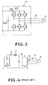
- Fig. 3 shows a three-phase transistor inverter employed as the inverters of the electric vehicle.
- the inverter 4 used in the drive system of Fig. 2 is explained in the description below, the inverters 41 and 42 in the drive system of Fig. 1 are similar.
- reference numeral 401 denotes transistors
- 402 designates diodes, each of which is connected in antiparallel with each one of the transistors 401.
- the main circuit of the three-phase inverter comprises six arms each of which includes the transistor 401 and the diode 402.
- Reference numeral 403 denotes a capacitor for smoothing the current of the secondary battery 1.
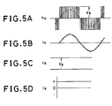
- Figs. 5A - 5D and 6A - 6D illustrate the waveforms of the input and output currents and voltages of the inverter while driving the electric vehicle.
- inverters for driving an electric vehicle employ the PWM control like inverters employed for driving AC motors widely used in industry.
- the inverter 4 of Fig. 3 also uses the PWM control.
- Fig. 4 illustrates the voltages and currents in Figs. 5A - 5D which illustrate waveforms in the motoring mode, and in Figs. 6A - 6D which illustrate waveforms in the regenerative braking mode. As seen from Figs.
- the AC side voltage V M of the inverter 4 has a waveform obtained by performing the PWM control on the voltage V B of the secondary battery 1. This waveform is similar in both motoring mode and regenerative braking mode.
- the dotted curve shown in the waveform of the voltage V M indicates the fundamental wave of the PWM control.
- the PWM control performs such control as the fundamental wave becomes a sine-wave.
- the AC side current i M of the inverter 4 has a waveform in which higher harmonic current is superimposed on the sinusoidal fundamental wave.
- the waveforms shown Figs. 5A - 5D and 6A - 6D indicate that the power factor is 1.0 in this case.
- the phase of the current i M in the regenerative braking mode is opposite to that in the motoring mode so that the regenerative operation is performed.
- the current i B at the DC side of the inverter 4 is also reversed in the regenerative braking mode.
- the stored energy in the secondary battery of the electric vehicle is limited, it must be charged at times, and this is essential in using the electric vehicle. In other words, the charging of the secondary battery and a charging system are essential in using the electric vehicle.
- Fig. 7 shows a conventional charging system.
- reference numeral 100 designates an electric vehicle comprising the same elements as shown in Fig. 2.
- reference numeral 300 denotes a charging system which is connected to a charging connector 200 via charging cables 400 at the DC side, and to a connector 600 via cables 700 at the AC side.
- the charging connector 200 is connected to the secondary battery 1, and the connector 600 is connected to a distribution network 500.
- the main switch 2 in the electric vehicle 100 is opened, and the secondary battery 1 is charged with the DC power supplied from the charging system 300 which rectifies the AC power supplied from the distribution network 500.
- Fig. 8 illustrates a conventional charging system 300.
- reference numeral 301 designates a switch at the AC side of the system; 302, a step-down transformer provided as needed; 303, a rectifier made of diodes which rectifies an AC voltage into a DC voltage; 304, a chopper for controlling the charging current; 305, a reactor for smoothing the charging current; and 306, a fuse.
- the charging system 300 is usually required to quickly charge the secondary battery 1 except when it is allowed to take enough time for charging. Accordingly, the capacity of the charging system must be at least equal to that of the inverter for driving the AC motor of the electric vehicle. Thus, since the charging system must have a large capacity and incorporate a power converter like the diode rectifier 303, the dimension of the charging system becomes large, and the charging operation requires wide space.
- Fig. 9 illustrates the charging operation of the electric vehicle 100.
- the charging system 300 is bulky and expensive, it is difficult to locate it at many spots, and this presents a problem in spreading the electromobiles.
- the charging system 300 since the charging system 300 has a rectifying load which is to be connected to the distribution network 500, it induces higher harmonics on the distribution network 500, or reduces the power factor. This presents a problem that the power quality on the distribution network is deteriorated.
- an electric system for an electric vehicle comprising: an AC motor for driving one or more wheels; a secondary battery for supplying DC power; power converting means for converting the DC power supplied from the secondary battery to AC power to be supplied to the AC motor, the power converting means having a regenerative function which rectifies AC power to DC power so that the DC power is regenerated to the secondary battery; means for disconnecting a connection between the power converting means and the AC motor during charging of the secondary battery; and means for supplying an AC voltage to an AC side of the power converting means during the charging, wherein the power converting means rectifies the AC voltage applied to the AC side thereof to a DC voltage during charging so that the secondary battery is charged by the DC voltage.
- the power converting means may be an inverter which carries out PWM control during charging of the secondary battery.
- the AC motor, the power converting means, the means for disconnecting and the means for supplying may be of three-phase.
- the AC motor and the power converting means may be of three-phase, whereas the means for disconnecting and the means for supplying may be of single-phase.
- An electric system for an electric vehicle may further comprise reactor provided between the means for supplying and the power converting means.
- An electric system for an electric vehicle may further comprise a step-down transformer inserted between the means for supplying and the power converting means.
- the peak value of the output voltage of the step-down transformer may be set lower than the DC voltage applied to the secondary battery.
- An electric system for an electric vehicle may further comprise a fuse inserted between the means for supplying and the power converting means.
- an electric system for an electric vehicle comprising: an AC motor for driving one or more wheels; a secondary battery for supplying DC power; power converting means for converting the DC power supplied from the secondary battery to AC power to be supplied to the AC motor, the power converting means having a regenerative function which rectifies the AC power to DC power so that the DC power is regenerated to the secondary battery; means for supplying an AC voltage to an AC side of the power converting means during charging; and means for connecting windings of the AC motor in such a fashion that the windings are inserted between the means for supplying and the power converting means during the charging, wherein the power converting means rectifies the AC voltage applied to the AC side thereof to a DC voltage during charging so that the secondary battery is charged by the DC voltage.
- the means for connecting may comprise a switch for switching the windings of the AC motor in such a fashion that the windings are inserted between the means for supplying and the power converting means during the charging, and take a normal motor winding configuration during driving of the wheels.
- the AC motor may be of three-phase, and the windings of the AC motor may be star-connected during driving of the wheels.
- the AC motor may be of three-phase, and the windings of the AC motor may be delta-connected during driving of the wheels.
- An electric system for an electric vehicle may further comprise means for operating the switch automatically when starting the charging of the secondary battery.
- the power converting system may be an inverter which carries out PWM control during charging of the secondary battery.
- the AC motor, the power converting means, the means for connecting and the means for supplying may be of three-phase.
- the AC motor and the power converting means may be of three-phase, whereas the means for connecting and the means for supplying may be of single-phase.
- An electric system for an electric vehicle may further comprise a step-down transformer inserted between the means for supplying and the power converting means.
- the peak value of the output voltage of the step-down transformer may be set lower than the DC voltage applied to the secondary battery.
- An electric system for an electric vehicle may further comprise a fuse inserted between the means for supplying and the power converting means.
- An electric system for an electric vehicle may further comprise a brake for braking the wheels of the electric vehicle.
- the power converting means like an inverter is disconnected from the AC motor during charging of the secondary battery, and the power supplying means like a distribution network is connected to the AC side of the power converting means.
- the power converting means operates as in the conventional regenerative braking mode wherein AC-to-DC conversion is performed so that the secondary battery is charged with the DC power.
- the PWM control performed during charging will reduce higher harmonics and distortion, enable the operation with a power factor of 1.0, and maintain the quality of the distribution network.
- both single- and three-phase power supplies can be employed, both household power supplies and factory power supplies can be used for charging.
- the AC side of the power converting means like an inverter is connected to the power supplying means like a distribution network via the windings of the AC motor during charging of the secondary battery.
- the power converting means operates as in the conventional regenerative braking mode in order to charge the secondary battery.
- the windings of the AC motor connected between the power converting means and the power supplying means function as reactance greatly reducing the higher harmonics generated by the PWM control or the like of the power converting means.
- the integrity of the current waveforms of the power supplying means is maintained.
- Fig. 10 shows the arrangement of a first embodiment of the present invention.
- the same reference numerals designate the same or corresponding elements in Fig. 2, and the description thereof is omitted here.
- the inverter 4 executes both rectifying and inverting operations.
- AC connecting wires 62 of the inverter 4 are connected to motor connecting wires 63 via a switch 60.
- the connecting wires 62 are also connected to a charging AC connector or terminals 210 (both AC connector and terminals are referred to as an AC connector below for the purpose of simplicity) by way of connecting wires 64.
- an AC connector or terminals 610 (both AC connector and terminals are called as an AC connector like the AC connector 210) is connected to a three-phase distribution network 500.
- charging cables 410 including AC reactors 710 are connected between the AC connectors 210 and 610.
- the AC reactors 710 can be removed when the distribution network 500 includes a certain amount of reactance.
- the switch 60 is closed when the secondary battery 1 of the electric vehicle is not charged so that the AC power outputted from the inverter 4 is supplied to an AC motor 5 so as to drive it.
- the switch 60 is automatically opened by a suitable mechanism not shown so that the voltage on the distribution network 500 is not directly applied to the AC motor 5.
- the inverter 4 further comprises a control circuit 4A so as to control its operation.
- the secondary battery 1 of the electric vehicle 100 is connected to the distribution network 500 via the inverter 4, connecting wires 62 and 64, the AC connector 210, the charging cables 410, and the connector 610, and then, a main switch 2 is closed. Then, the control of the inverter 4 is manually switched from a motor control mode (corresponding to the motoring mode) to a charging control mode (corresponding to the regenerative braking mode) so that the AC to DC conversion is performed under the PWM control in such a manner that the charging current and voltage to the secondary battery 1 are regulated to preset values.
- a motor control mode corresponding to the motoring mode
- a charging control mode corresponding to the regenerative braking mode
- Figs. 11A - 11E illustrate the voltages and currents of some portions of the inverter 4 when it is in the charging mode.
- the voltages and currents are substantially equivalent to those in Figs. 6A - 6D which illustrate the regenerative braking operation. It must be noted here that the directions of currents are reversed this case, as seen by comparing Fig. 4 and Fig. 10.
- the voltage of the secondary battery 1 be higher than the peak value of the sine-wave AC voltage on the distribution network 500.
- the voltage of the secondary battery 1 which is slightly lower than the peak value of the AC voltage may be allowed because an excessive charging current is limited by the internal resistance of the battery in this case, a lower voltage will cause a charging current that cannot be controlled by the diodes constituting the inverter 4 so that an overcurrent might often break a fuse 3, thereby opening the charging circuit.
- the inverter 4 which has not been conventionally used to charge the battery is utilized as the AC to DC converter so that the DC output thereof is used to charge the secondary battery 1.
- the electric vehicle 100 it is enough for the electric vehicle 100 to further comprise the switch 60, the connecting wires 64, the AC connector 210, and the charging control circuit 4A in the inverter 4 which is also needed conventionally, and for the AC power line to further comprise the AC connector 610, and the AC reactors 710 when required, in addition to the cables 410 which are also needed conventionally.
- this embodiment can realize a very low cost and space-saving charging system.
- the current i S supplied from the distribution network 500 to the electric vehicle 100 during the charging operation can take a nearly complete sinusoidal waveform with small distortion as shown in Fig. 11C. This makes it possible to accomplish the charging operation whose power factor is 1.0. This will also ensure that the quality of the power on the distribution network 500 is maintained.
- Fig. 12 show a second embodiment of the present invention. This embodiment is applied to a single-phase distribution network 520.
- AC connectors 220 and 620 the AC connector refers to the AC connector and terminals that may be used in place of the AC connector as mentioned before
- charging cables 420, AC reactors 720 when needed, connecting wires 64 and a switch 61 are all constructed in accordance with single-phase specifications.
- the inverter 4 and the AC motor 5 are, on the other hand, based on three-phase specifications so that a single inverter can deal with charges from the single-phase and three-phase distribution networks 520 and 500 by switching the single-phase/three-phase control of the inverter 4.
- Fig. 13 shows the main portion of a third embodiment of the present invention. It comprises a step-down transformer 800 inserted instead of the AC reactors 710 and 720 of the embodiments shown in Figs. 10 and 12.
- the system in Fig. 13 is applied to the three-phase distribution network 500, it can also be applied to a single-phase distribution network 520 as shown in Fig. 12.
- This embodiment is effective because of the following reasons: first, the windings of the step-down transformer 800 ensure some amount of reactances at the AC side of the inverter 4; and second, the step-down transformer 800 enables to supply the AC side of the inverter 4 with the lower AC voltage than the voltage of the secondary battery 1 even if the battery voltage is lower than the peak value of the AC voltage on the distribution network 500.
- the above-described embodiments may comprise fuses between the electric vehicle and the distribution network for protecting the devices of the inverter 4 from an overcurrent at the AC side of the inverter 4.
- the fuses may be serially connected with the AC reactors 710 or 720, or with the step-down transformer 800.
- an AC switch may be connected between the electric vehicle and the distribution network for the purpose of safety.
- These embodiments comprise the windings of the AC motor connected between the inverter and the AC power supply, and while the secondary battery is charged to operate the windings as a reactors.
- These embodiments are characterized in that they comprise a switch for switching the connection of the windings in accordance with the driving of the wheels by the AC motor, or the charging of the secondary battery.
- Fig. 14 shows an arrangement of the fourth embodiment of the present invention.
- like or corresponding elements are designated by the same reference numerals as in Fig. 10, and the description thereof is omitted here.
- the connecting lines 62 at the AC side of the inverter 4 are connected to first terminals 51a, 52a and 53a of the phase-windings 51, 52 and 53 of the AC motor 5, respectively.
- second terminals 51b, 52b and 53b of the phase-windings 51, 52 and 53 are connected, via the connecting wires 64, to first terminals 65a, 66a and 67a of a three-pole switch 60A, respectively.
- Second terminals 65b, 66b and 67b of the three-pole switch 60A are connected to the AC connector 210 via the connecting wires 68.
- the remaining third terminals 65c, 66c and 67c of the three-pole switch 60A are connected with each other.
- the external three-phase distribution network 500 is connected to the AC connector 610 as mentioned before.
- the charging cables 410 are connected between the AC connectors 210 and 610.
- This embodiment employs a three-phase induction motor as the AC motor, and the windings thereof are star-connected (Y-connected).
- the terminals 65a, 66a and 67a of the three-pole switch 60A are connected to the terminals 65c, 66c and 67c thereof so that the windings 51, 52 and 53 are star-connected.
- the windings 51, 52 and 53 are disconnected from the AC connector 210 or the distribution network 500 so that the motor 5 can operate as an AC motor.
- Fig. 15 shows the connection in this case.
- the windings 51, 52 and 53 are star-connected in the motoring mode, and hence, the AC motor 5 is driven by the AC power supplied from the inverter 4.
- the inverter 4 performs the power conversion opposite to that in the motoring mode so that the power is regenerated to the secondary battery 1 through the inverter 4.
- the terminals 65a, 66a and 67a of the three-pole switch 60A are connected to the terminals 65b, 66b and 67b thereof so that the windings 51, 52 and 53 are connected to the distribution network 500 via the AC connectors 210 and 610.
- Fig. 16 shows the connection in this case.
- the windings 51, 52 and 53 function in the same manner as the AC reactors 710 in Fig. 10 or the AC reactors 720 in Fig. 12.
- the charging power is supplied from the distribution network 500 to the inverter 4 by way of the windings 51, 52 and 53, and the inverter 4 converts the AC power into the DC power so that the secondary battery 1 is charged in the same manner as in the regenerative braking mode.
- the inverter 4 comprises a control circuit 4A for controlling the charging operation.
- Fig. 17 shows the fifth embodiment of present invention.
- the windings 51, 52 and 53 of the AC motor 5 are delta-connected.
- the fifth embodiment differs from the fourth embodiment in the connection between the windings 51, 52 and 53 and the three-phase switch 60A, and the other portions are substantially the same as those of the fourth embodiment.
- Fig. 18 shows the connection when the AC motor 5 drives the wheels in this embodiment
- Fig. 19 shows the connection when the secondary battery 1 is charged. Since the operation is similar to that of the first embodiment except that the AC motor 5 is delta-connected during the wheel driving, the description thereof is omitted here.
- Fig. 20 shows an equivalent circuit during the charging of the secondary battery 1
- Fig. 21 illustrates the waveforms of the current and voltages of various portions.
- reference numeral 5x designates the reactance of the windings 51, 52 and 53; 410x, the reactance of the cables 410; 500x, the reactance in the distribution network 500; and 601 and 602, other AC loads connected to the distribution network 500.
- a character V B denotes the voltage of the secondary battery 1; i B , the current of the secondary battery 1 during charging; i S , the current at the AC side of the inverter 4 during charging; and V S , the voltage at the AC side of the inverter 4 during charging.
- the inverter 4 since the inverter 4 performs PWM control by using a high frequency more than several kHz, the current i S supplied from the distribution network 500 becomes a sine-wave including a small amount of high frequency ripples as shown in Fig. 21. Here, the power factor of the sine-wave becomes about 1.0.
- the voltage at the AC side of the inverter 4 takes a PWM waveform whose peak value is equal to the battery voltage V B as indicated by V S1 .
- the reactance 5x is much larger than the reactance 410x, a large part of the PWM waveform is absorbed by the reactance 5x so that the voltage V S2 at the connector 210 of the electric vehicle takes a waveform of nearly a sine-wave.
- the voltage at the connector 610 (Fig. 14) on the side of the distribution network 500 further approaches a sine-wave as indicated by V S3 .
- the fourth and fifth embodiments have the phase windings of the AC motor inserted between the external AC power supply and the inverter for driving the AC motor, and charge the secondary battery with the DC current from the inverter which converts the power from the external AC power supply using the reactance of the windings of the AC motor.
- Fig. 22 illustrates an equivalent circuit in charging the secondary battery when an induction motor is employed as the AC motor 5.
- the equivalent circuit of the AC motor (the induction motor) 5 itself is well-known.
- X1 and R1 designate a leakage reactance and a winding resistance of the stator windings, which generally have a relationship X1 >> R1 so that the winding resistance R1 can be neglected.
- X2' and R2 ⁇ denote a reactance and a resistance of the rotor; S, a slip; Xm, an excitation reactance; V, a voltage applied to the motor 5; and V m , an exciting voltage.
- the reactance X1 + X2' is usually on the order of 10% in terms of % reactance. This means that the voltage V across the motor is about 10% of the rated voltage if the charge current I S is the rated current of the motor 5. Further, since the reactances X1 and X2' take a similar value, the exciting voltage Vm becomes about 5% of the rated voltage.
- the torque generated by the induction motor is proportional to the square of the voltage, the torque developed during charging becomes (5/100)2 or 0.25% of the rated torque.
- charging using the windings of the motor produces so small torque less than 1% of the rated torque that there is no possibility that the electric vehicle will start moving. It is preferable, however, to apply the parking brake during charging for the purpose of safety.
- the charging voltage of the secondary battery 1 be higher than the peak value of the voltage at the AC side of the inverter 4, that is, the peak value of the AC voltage on the distribution network 500.
- circuits for driving the motor and for charging the secondary battery are formed by switching the three-pole switch 60A in the embodiments associated with Figs. 14 and 17, it is preferable that the circuit for driving the motor be transferred to the circuit for charging by automatically changing the switch when starting a charging. This will be accomplished by providing a mechanical structure such that connecting the charging cables 410 to the AC connector 210 enables the switch to automatically operate to transfer the circuits.
- fuses be inserted between the distribution network 500 and the AC side of the inverter 4 for the purpose of protecting the circuit during the charging.
- the inverter 4 which has not been conventionally used during the charging, can be utilized as an AC-to-DC converter for charging the secondary battery 1.
- the inverter 4 which has not been conventionally used during the charging, can be utilized as an AC-to-DC converter for charging the secondary battery 1.
- the current i s supplied from the distribution network 500 to the electric vehicle 100 during the charging operation can take a nearly complete sinusoidal waveform with small distortion as shown in Fig. 21. This makes it possible to accomplish the charging operation whose power factor is 1.0. This will also ensure that the integrity of the power on the distribution network 500 is maintained.
- the present invention can be applied to a synchronous motor, as well.
- the torque generated by the synchronous motor during charging is zero, and hence, no torque is generated to drive the electric vehicle, there is no fear that the electric vehicle starts moving.
- Figs. 14 and 17 are for the three-phase external power supply such as the distribution network 500, they can also be applied to a single-phase power supply as the other embodiments.
Abstract
Description
- The present invention relates to an electric system for an electric vehicle comprising a secondary battery as a power supply.
- Fig. 1 shows a power train for a conventional electric vehicle having a secondary battery as its power supply. Each of the wheels of the electric vehicle is driven separately by an AC motor.
- In this figure,
reference numeral 1 designates a secondary battery; 2, a main switch; 31 and 32, fuses; 41 and 42, three-phase inverters as a power converter having a regenerative function; 51 and 52, AC motors; 61 and 62, connecting wires connecting theinverters AC motors AC motors reduction gears 71 and 72, and are transmitted to thewheels - Fig. 2 shows a power train which drives two wheels at the same time by one AC motor. In this figure,
reference numeral 3 denotes a fuse; 4, an inverter; 5, an AC motor; 6, connecting wires; 7, a reduction gear; and 9, a differential gear. The other components are the same as those in Fig. 1. - In the drive systems in Figs. 1 and 2, each of the
inverters secondary battery 1 to the AC power so as to control the torque and the rotation rates of theAC motors - In the motoring mode of the electric vehicle, the power of the
secondary battery 1 is DC-to-AC converted by the inverters, and is supplied to the motors from the inverters, thus driving the wheels. In contrast with this, in the regenerative braking mode, braking is performed by rectifying AC to DC by the inverters so that the kinetic energy of the electric vehicle is regenerated as the DC power to thesecondary battery 1 via the wheels, motors and inverters. - Fig. 3 shows a three-phase transistor inverter employed as the inverters of the electric vehicle. Although the
inverter 4 used in the drive system of Fig. 2 is explained in the description below, theinverters - In Fig. 3,
reference numeral 401 denotes transistors, and 402 designates diodes, each of which is connected in antiparallel with each one of thetransistors 401. The main circuit of the three-phase inverter comprises six arms each of which includes thetransistor 401 and thediode 402.Reference numeral 403 denotes a capacitor for smoothing the current of thesecondary battery 1. - Figs. 5A - 5D and 6A - 6D illustrate the waveforms of the input and output currents and voltages of the inverter while driving the electric vehicle. Generally, inverters for driving an electric vehicle employ the PWM control like inverters employed for driving AC motors widely used in industry. The
inverter 4 of Fig. 3 also uses the PWM control. Fig. 4 illustrates the voltages and currents in Figs. 5A - 5D which illustrate waveforms in the motoring mode, and in Figs. 6A - 6D which illustrate waveforms in the regenerative braking mode. As seen from Figs. 5A - 5D and 6A - 6D, the AC side voltage VM of theinverter 4 has a waveform obtained by performing the PWM control on the voltage VB of thesecondary battery 1. This waveform is similar in both motoring mode and regenerative braking mode. The dotted curve shown in the waveform of the voltage VM indicates the fundamental wave of the PWM control. The PWM control performs such control as the fundamental wave becomes a sine-wave. The AC side current iM of theinverter 4 has a waveform in which higher harmonic current is superimposed on the sinusoidal fundamental wave. - The waveforms shown Figs. 5A - 5D and 6A - 6D indicate that the power factor is 1.0 in this case. As shown in these figures, the phase of the current iM in the regenerative braking mode is opposite to that in the motoring mode so that the regenerative operation is performed. The current iB at the DC side of the
inverter 4 is also reversed in the regenerative braking mode. - Since the stored energy in the secondary battery of the electric vehicle is limited, it must be charged at times, and this is essential in using the electric vehicle. In other words, the charging of the secondary battery and a charging system are essential in using the electric vehicle.
- Fig. 7 shows a conventional charging system. In this figure,
reference numeral 100 designates an electric vehicle comprising the same elements as shown in Fig. 2. - In Fig. 7,
reference numeral 300 denotes a charging system which is connected to acharging connector 200 viacharging cables 400 at the DC side, and to aconnector 600 via cables 700 at the AC side. Thecharging connector 200 is connected to thesecondary battery 1, and theconnector 600 is connected to adistribution network 500. - When charging the
secondary battery 1, themain switch 2 in theelectric vehicle 100 is opened, and thesecondary battery 1 is charged with the DC power supplied from thecharging system 300 which rectifies the AC power supplied from thedistribution network 500. - Fig. 8 illustrates a
conventional charging system 300. In Fig. 8,reference numeral 301 designates a switch at the AC side of the system; 302, a step-down transformer provided as needed; 303, a rectifier made of diodes which rectifies an AC voltage into a DC voltage; 304, a chopper for controlling the charging current; 305, a reactor for smoothing the charging current; and 306, a fuse. - The
charging system 300 is usually required to quickly charge thesecondary battery 1 except when it is allowed to take enough time for charging. Accordingly, the capacity of the charging system must be at least equal to that of the inverter for driving the AC motor of the electric vehicle. Thus, since the charging system must have a large capacity and incorporate a power converter like thediode rectifier 303, the dimension of the charging system becomes large, and the charging operation requires wide space. - Fig. 9 illustrates the charging operation of the
electric vehicle 100. - It is essential to locate charging stations as shown in Fig. 9 at various sites as gasoline stations for automobiles with an internal combustion engine so that electric vehicle can run without restriction of time and space.
- In the conventional charging system, however, since the
charging system 300 is bulky and expensive, it is difficult to locate it at many spots, and this presents a problem in spreading the electromobiles. - In addition, since the
charging system 300 has a rectifying load which is to be connected to thedistribution network 500, it induces higher harmonics on thedistribution network 500, or reduces the power factor. This presents a problem that the power quality on the distribution network is deteriorated. - It is therefore an object of the present invention to provide an electric system for an electric vehicle which can charge its secondary battery by only connecting a simple apparatus to an AC power supply like a distribution network without using a bulky, expensive charging system.
- It is another object of the present invention to provide an electric system which can maintain the integrity of the power on the distribution network during charging.
- According to a first aspect of the present invention, there is provided an electric system for an electric vehicle comprising:
an AC motor for driving one or more wheels;
a secondary battery for supplying DC power;
power converting means for converting the DC power supplied from the secondary battery to AC power to be supplied to the AC motor, the power converting means having a regenerative function which rectifies AC power to DC power so that the DC power is regenerated to the secondary battery;
means for disconnecting a connection between the power converting means and the AC motor during charging of the secondary battery; and
means for supplying an AC voltage to an AC side of the power converting means during the charging,
wherein the power converting means rectifies the AC voltage applied to the AC side thereof to a DC voltage during charging so that the secondary battery is charged by the DC voltage. - Here, the power converting means may be an inverter which carries out PWM control during charging of the secondary battery.
- The AC motor, the power converting means, the means for disconnecting and the means for supplying may be of three-phase.
- The AC motor and the power converting means may be of three-phase, whereas the means for disconnecting and the means for supplying may be of single-phase.
- An electric system for an electric vehicle may further comprise reactor provided between the means for supplying and the power converting means.
- An electric system for an electric vehicle may further comprise a step-down transformer inserted between the means for supplying and the power converting means.
- The peak value of the output voltage of the step-down transformer may be set lower than the DC voltage applied to the secondary battery.
- An electric system for an electric vehicle may further comprise a fuse inserted between the means for supplying and the power converting means.
- According to a second aspect of the present invention, there is provided an electric system for an electric vehicle comprising:
an AC motor for driving one or more wheels;
a secondary battery for supplying DC power;
power converting means for converting the DC power supplied from the secondary battery to AC power to be supplied to the AC motor, the power converting means having a regenerative function which rectifies the AC power to DC power so that the DC power is regenerated to the secondary battery;
means for supplying an AC voltage to an AC side of the power converting means during charging; and
means for connecting windings of the AC motor in such a fashion that the windings are inserted between the means for supplying and the power converting means during the charging,
wherein the power converting means rectifies the AC voltage applied to the AC side thereof to a DC voltage during charging so that the secondary battery is charged by the DC voltage. - Here, the means for connecting may comprise a switch for switching the windings of the AC motor in such a fashion that the windings are inserted between the means for supplying and the power converting means during the charging, and take a normal motor winding configuration during driving of the wheels.
- The AC motor may be of three-phase, and the windings of the AC motor may be star-connected during driving of the wheels.
- The AC motor may be of three-phase, and the windings of the AC motor may be delta-connected during driving of the wheels.
- An electric system for an electric vehicle may further comprise means for operating the switch automatically when starting the charging of the secondary battery.
- The power converting system may be an inverter which carries out PWM control during charging of the secondary battery.
- The AC motor, the power converting means, the means for connecting and the means for supplying may be of three-phase.
- The AC motor and the power converting means may be of three-phase, whereas the means for connecting and the means for supplying may be of single-phase.
- An electric system for an electric vehicle may further comprise a step-down transformer inserted between the means for supplying and the power converting means.
- The peak value of the output voltage of the step-down transformer may be set lower than the DC voltage applied to the secondary battery.
- An electric system for an electric vehicle may further comprise a fuse inserted between the means for supplying and the power converting means.
- An electric system for an electric vehicle may further comprise a brake for braking the wheels of the electric vehicle.
- According to the first aspect of the present invention, the power converting means like an inverter is disconnected from the AC motor during charging of the secondary battery, and the power supplying means like a distribution network is connected to the AC side of the power converting means. The power converting means operates as in the conventional regenerative braking mode wherein AC-to-DC conversion is performed so that the secondary battery is charged with the DC power.
- Thus, since no bulky charging apparatus is required incorporating a rectifier such as a diode rectifier, chopper or the like, a low cost, small, space-saving electric system can be realized.
- Furthermore, the PWM control performed during charging will reduce higher harmonics and distortion, enable the operation with a power factor of 1.0, and maintain the quality of the distribution network.
- In addition, since both single- and three-phase power supplies can be employed, both household power supplies and factory power supplies can be used for charging.
- According to the second aspect of the present invention, the AC side of the power converting means like an inverter is connected to the power supplying means like a distribution network via the windings of the AC motor during charging of the secondary battery. Thus, the power converting means operates as in the conventional regenerative braking mode in order to charge the secondary battery.
- The windings of the AC motor connected between the power converting means and the power supplying means function as reactance greatly reducing the higher harmonics generated by the PWM control or the like of the power converting means. Thus, the integrity of the current waveforms of the power supplying means is maintained.
- The above and other objects, effects, features and advantages of the present invention will become more apparent from the following description of the embodiments thereof taken in conjunction with the accompanying drawings.
- Fig. 1 is a block diagram showing a power train for a conventional electric vehicle;
- Fig. 2 is a block diagram showing another power train for a conventional electric vehicle;
- Fig. 3 is a circuit diagram showing a main circuit of a three-phase transistor inverter;
- Fig. 4 is a block diagram showing a major portion of the power train shown in Fig. 2;
- Figs. 5A - 5D illustrate waveforms of input and output voltages and currents of the inverter as shown in Fig. 3 when the inverter is operated in the motoring mode;
- Figs. 6A - 6D illustrate waveforms of input and output voltages and currents of the inverter as shown in Fig. 3 when the inverter is operated in the regenerative braking mode;
- Fig. 7 is a block diagram showing an arrangement of a conventional charging system;
- Fig. 8 is a block diagram showing an arrangement of another conventional charging system;
- Fig. 9 is a diagram illustrating a conventional charging system;
- Fig. 10 is a block diagram showing the arrangement of a first embodiment of an electric system for an electric vehicle in accordance with the present invention;
- Figs. 11A - 11E illustrate waveforms of voltages and currents of some portions of the electric system of Fig. 10 during charging;
- Fig. 12 is a block diagram showing the arrangement of a second embodiment of an electric system for an electric vehicle in accordance with the present invention;
- Fig. 13 is a block diagram showing the main portion of a third embodiment of an electric system for an electric vehicle in accordance with the present invention;
- Fig. 14 is a block diagram showing the arrangement of a fourth embodiment of an electric system for an electric vehicle in accordance with the present invention;
- Fig. 15 is a block diagram showing the connection of the windings of the AC motor when the AC motor drives the wheels in the fourth embodiment shown in Fig. 14;
- Fig. 16 is a block diagram showing the connection of the windings of the AC motor when the secondary battery is charged through the windings in the fourth embodiment shown in Fig. 14;
- Fig. 17 is a block diagram showing the main portion of a fifth embodiment of the present invention;
- Fig. 18 is a block diagram showing the connection of the windings of the AC motor when the AC motor drives the wheels in the fifth embodiment shown in Fig. 17;
- Fig. 19 is a block diagram showing the connection of the windings of the AC motor when the secondary battery is charged through the windings in the fifth embodiment shown in Fig. 17;
- Fig. 20 is an equivalent circuit of the fourth and fifth embodiments shown in Figs. 14 and 17 during charging of the secondary battery;
- Fig. 21 is a diagram illustrating voltages and current of various portions in the equivalent circuit shown in Fig. 20; and
- Fig. 22 is an equivalent circuit in charging he secondary battery when an induction motor is employed as the AC motor.
- The invention will now be described with reference to the accompanying drawings.
- Fig. 10 shows the arrangement of a first embodiment of the present invention. In this figure, the same reference numerals designate the same or corresponding elements in Fig. 2, and the description thereof is omitted here.
- In the
electric vehicle 100 of this embodiment, theinverter 4 executes both rectifying and inverting operations.AC connecting wires 62 of theinverter 4 are connected tomotor connecting wires 63 via aswitch 60. In addition, the connectingwires 62 are also connected to a charging AC connector or terminals 210 (both AC connector and terminals are referred to as an AC connector below for the purpose of simplicity) by way of connectingwires 64. - And, as an external AC power supply, an AC connector or terminals 610 (both AC connector and terminals are called as an AC connector like the AC connector 210) is connected to a three-
phase distribution network 500. When thesecondary battery 1 of theelectric vehicle 100 is charged, chargingcables 410 includingAC reactors 710 are connected between theAC connectors AC reactors 710 can be removed when thedistribution network 500 includes a certain amount of reactance. - The
switch 60 is closed when thesecondary battery 1 of the electric vehicle is not charged so that the AC power outputted from theinverter 4 is supplied to anAC motor 5 so as to drive it. On the other hand, when the chargingcables 410 are connected to theAC connector 210 to charge thesecondary battery 1, theswitch 60 is automatically opened by a suitable mechanism not shown so that the voltage on thedistribution network 500 is not directly applied to theAC motor 5. - The
inverter 4 further comprises acontrol circuit 4A so as to control its operation. - Next, the charging operation in accordance with this embodiment will be described with reference to Figs. 11A - 11E. As described above, the
secondary battery 1 of theelectric vehicle 100 is connected to thedistribution network 500 via theinverter 4, connectingwires AC connector 210, the chargingcables 410, and theconnector 610, and then, amain switch 2 is closed. Then, the control of theinverter 4 is manually switched from a motor control mode (corresponding to the motoring mode) to a charging control mode (corresponding to the regenerative braking mode) so that the AC to DC conversion is performed under the PWM control in such a manner that the charging current and voltage to thesecondary battery 1 are regulated to preset values. - Figs. 11A - 11E illustrate the voltages and currents of some portions of the
inverter 4 when it is in the charging mode. The voltages and currents are substantially equivalent to those in Figs. 6A - 6D which illustrate the regenerative braking operation. It must be noted here that the directions of currents are reversed this case, as seen by comparing Fig. 4 and Fig. 10. - In the charging mode, it is preferable that the voltage of the
secondary battery 1 be higher than the peak value of the sine-wave AC voltage on thedistribution network 500. Although the voltage of thesecondary battery 1 which is slightly lower than the peak value of the AC voltage may be allowed because an excessive charging current is limited by the internal resistance of the battery in this case, a lower voltage will cause a charging current that cannot be controlled by the diodes constituting theinverter 4 so that an overcurrent might often break afuse 3, thereby opening the charging circuit. - In accordance with this embodiment, the
inverter 4 which has not been conventionally used to charge the battery is utilized as the AC to DC converter so that the DC output thereof is used to charge thesecondary battery 1. - Accordingly, from the viewpoint of the total system for charging the battery, it is enough for the
electric vehicle 100 to further comprise theswitch 60, the connectingwires 64, theAC connector 210, and the chargingcontrol circuit 4A in theinverter 4 which is also needed conventionally, and for the AC power line to further comprise theAC connector 610, and theAC reactors 710 when required, in addition to thecables 410 which are also needed conventionally. As a result, this embodiment can realize a very low cost and space-saving charging system. - Moreover, by carrying out the PWM control of the
inverter 4, the current iS supplied from thedistribution network 500 to theelectric vehicle 100 during the charging operation can take a nearly complete sinusoidal waveform with small distortion as shown in Fig. 11C. This makes it possible to accomplish the charging operation whose power factor is 1.0. This will also ensure that the quality of the power on thedistribution network 500 is maintained. - Fig. 12 show a second embodiment of the present invention. This embodiment is applied to a single-
phase distribution network 520. In connection with this,AC connectors 220 and 620 (the AC connector refers to the AC connector and terminals that may be used in place of the AC connector as mentioned before), chargingcables 420,AC reactors 720 when needed, connectingwires 64 and aswitch 61 are all constructed in accordance with single-phase specifications. - The
inverter 4 and theAC motor 5 are, on the other hand, based on three-phase specifications so that a single inverter can deal with charges from the single-phase and three-phase distribution networks inverter 4. - Fig. 13 shows the main portion of a third embodiment of the present invention. It comprises a step-down
transformer 800 inserted instead of theAC reactors phase distribution network 500, it can also be applied to a single-phase distribution network 520 as shown in Fig. 12. - This embodiment is effective because of the following reasons: first, the windings of the step-down
transformer 800 ensure some amount of reactances at the AC side of theinverter 4; and second, the step-downtransformer 800 enables to supply the AC side of theinverter 4 with the lower AC voltage than the voltage of thesecondary battery 1 even if the battery voltage is lower than the peak value of the AC voltage on thedistribution network 500. - The above-described embodiments may comprise fuses between the electric vehicle and the distribution network for protecting the devices of the
inverter 4 from an overcurrent at the AC side of theinverter 4. The fuses may be serially connected with theAC reactors transformer 800. In addition, an AC switch may be connected between the electric vehicle and the distribution network for the purpose of safety. - Next, fourth and fifth embodiments of the present invention will be described. These embodiments comprise the windings of the AC motor connected between the inverter and the AC power supply, and while the secondary battery is charged to operate the windings as a reactors. These embodiments are characterized in that they comprise a switch for switching the connection of the windings in accordance with the driving of the wheels by the AC motor, or the charging of the secondary battery.
- Fig. 14 shows an arrangement of the fourth embodiment of the present invention. In this figure, like or corresponding elements are designated by the same reference numerals as in Fig. 10, and the description thereof is omitted here.
- In the
electric vehicle 100 of Fig. 14, the connectinglines 62 at the AC side of theinverter 4 are connected tofirst terminals windings AC motor 5, respectively. On the other hand,second terminals windings wires 64, tofirst terminals pole switch 60A, respectively.Second terminals pole switch 60A are connected to theAC connector 210 via the connectingwires 68. The remainingthird terminals pole switch 60A are connected with each other. - And, the external three-
phase distribution network 500 is connected to theAC connector 610 as mentioned before. When thesecondary battery 1 of theelectric vehicle 100 is charged, the chargingcables 410 are connected between theAC connectors - This embodiment employs a three-phase induction motor as the AC motor, and the windings thereof are star-connected (Y-connected).
- Next, the operation of the fourth embodiment will be described below.
- When the
AC motor 5 operates to drive the wheels, theterminals pole switch 60A are connected to theterminals windings windings AC connector 210 or thedistribution network 500 so that themotor 5 can operate as an AC motor. - Fig. 15 shows the connection in this case. As described above, the
windings AC motor 5 is driven by the AC power supplied from theinverter 4. In contrast, in the regenerative braking mode, theinverter 4 performs the power conversion opposite to that in the motoring mode so that the power is regenerated to thesecondary battery 1 through theinverter 4. - On the other hand, when the
secondary battery 1 is charged, theterminals pole switch 60A are connected to theterminals windings distribution network 500 via theAC connectors - Fig. 16 shows the connection in this case. The
windings AC reactors 710 in Fig. 10 or theAC reactors 720 in Fig. 12. The charging power is supplied from thedistribution network 500 to theinverter 4 by way of thewindings inverter 4 converts the AC power into the DC power so that thesecondary battery 1 is charged in the same manner as in the regenerative braking mode. - For this purpose, the
inverter 4 comprises acontrol circuit 4A for controlling the charging operation. - Fig. 17 shows the fifth embodiment of present invention. In this embodiment, the
windings AC motor 5 are delta-connected. The fifth embodiment differs from the fourth embodiment in the connection between thewindings phase switch 60A, and the other portions are substantially the same as those of the fourth embodiment. - Fig. 18 shows the connection when the
AC motor 5 drives the wheels in this embodiment, whereas Fig. 19 shows the connection when thesecondary battery 1 is charged. Since the operation is similar to that of the first embodiment except that theAC motor 5 is delta-connected during the wheel driving, the description thereof is omitted here. - Fig. 20 shows an equivalent circuit during the charging of the
secondary battery 1, and Fig. 21 illustrates the waveforms of the current and voltages of various portions. - In Fig. 20,
reference numeral 5x designates the reactance of thewindings cables 410; 500x, the reactance in thedistribution network 500; and 601 and 602, other AC loads connected to thedistribution network 500. In addition, a character VB denotes the voltage of thesecondary battery 1; iB, the current of thesecondary battery 1 during charging; iS, the current at the AC side of theinverter 4 during charging; and VS, the voltage at the AC side of theinverter 4 during charging. - Generally, since the
inverter 4 performs PWM control by using a high frequency more than several kHz, the current iS supplied from thedistribution network 500 becomes a sine-wave including a small amount of high frequency ripples as shown in Fig. 21. Here, the power factor of the sine-wave becomes about 1.0. The voltage at the AC side of theinverter 4 takes a PWM waveform whose peak value is equal to the battery voltage VB as indicated by VS1. - Since the
reactance 5x is much larger than thereactance 410x, a large part of the PWM waveform is absorbed by thereactance 5x so that the voltage VS2 at theconnector 210 of the electric vehicle takes a waveform of nearly a sine-wave. The voltage at the connector 610 (Fig. 14) on the side of thedistribution network 500 further approaches a sine-wave as indicated by VS3. - Since the supply voltages to the other AC loads 601 and 602 connected to the
distribution network 500 take a substantially sine waveform as VS3, the influence of the charging of theelectric vehicle 100 on the power supply is nearly zero. As describe before, the fourth and fifth embodiments have the phase windings of the AC motor inserted between the external AC power supply and the inverter for driving the AC motor, and charge the secondary battery with the DC current from the inverter which converts the power from the external AC power supply using the reactance of the windings of the AC motor. - In this case, it must be fully ensured that the electric vehicle never starts moving by the torque generated in the motor during charging. This will be discussed in more detail.
- Fig. 22 illustrates an equivalent circuit in charging the secondary battery when an induction motor is employed as the
AC motor 5. The equivalent circuit of the AC motor (the induction motor) 5 itself is well-known. - In this figure, X₁ and R₁ designate a leakage reactance and a winding resistance of the stator windings, which generally have a relationship X₁ >> R₁ so that the winding resistance R₁ can be neglected. X₂' and R₂ʼ denote a reactance and a resistance of the rotor; S, a slip; Xm, an excitation reactance; V, a voltage applied to the
motor 5; and Vm, an exciting voltage. - The electric vehicle is stationary while charging the
secondary battery 1. In other words, the rotation rate is zero, and hence, the slip S is 1.0. When the slip S = 1.0, the relationship
- In addition, the reactance X₁ + X₂' is usually on the order of 10% in terms of % reactance. This means that the voltage V across the motor is about 10% of the rated voltage if the charge current IS is the rated current of the
motor 5. Further, since the reactances X₁ and X₂' take a similar value, the exciting voltage Vm becomes about 5% of the rated voltage. - Since the torque generated by the induction motor is proportional to the square of the voltage, the torque developed during charging becomes (5/100)² or 0.25% of the rated torque. Thus, charging using the windings of the motor produces so small torque less than 1% of the rated torque that there is no possibility that the electric vehicle will start moving. It is preferable, however, to apply the parking brake during charging for the purpose of safety.
- As described in the first embodiment with reference to Fig. 10, it is preferable that the charging voltage of the
secondary battery 1 be higher than the peak value of the voltage at the AC side of theinverter 4, that is, the peak value of the AC voltage on thedistribution network 500. A charging voltage to thesecondary battery 1, which is slightly lower than the peak value of the voltage at the AC side of theinverter 4, can be allowed. This is because the internal resistance of the battery will prevent the charging current from growing too large. - Although the circuits for driving the motor and for charging the secondary battery are formed by switching the three-
pole switch 60A in the embodiments associated with Figs. 14 and 17, it is preferable that the circuit for driving the motor be transferred to the circuit for charging by automatically changing the switch when starting a charging. This will be accomplished by providing a mechanical structure such that connecting the chargingcables 410 to theAC connector 210 enables the switch to automatically operate to transfer the circuits. - It is further preferable that fuses be inserted between the
distribution network 500 and the AC side of theinverter 4 for the purpose of protecting the circuit during the charging. - In the embodiments as shown in Figs. 14 and 17, the
inverter 4, which has not been conventionally used during the charging, can be utilized as an AC-to-DC converter for charging thesecondary battery 1. As a result, a low cost, space-saving charging system can be realized. - Moreover, by carrying out the PWM control of the
inverter 4, the current is supplied from thedistribution network 500 to theelectric vehicle 100 during the charging operation can take a nearly complete sinusoidal waveform with small distortion as shown in Fig. 21. This makes it possible to accomplish the charging operation whose power factor is 1.0. This will also ensure that the integrity of the power on thedistribution network 500 is maintained. - Although all the embodiments above are explained assuming that the AC motor is an induction motor, the present invention can be applied to a synchronous motor, as well. In this case, since the torque generated by the synchronous motor during charging is zero, and hence, no torque is generated to drive the electric vehicle, there is no fear that the electric vehicle starts moving.
- Although the embodiments of Figs. 14 and 17 are for the three-phase external power supply such as the
distribution network 500, they can also be applied to a single-phase power supply as the other embodiments. - Although specific embodiments of an electric system for an electric vehicle constructed in accordance with the present invention have been disclosed, it is not intended that the invention be restricted to either the specific configurations or the uses disclosed herein. Modifications may be made in a manner obvious to those skilled in the art. Accordingly, it is intended that the invention be limited only by the scope of the appended claims.
Claims (16)
- An electric system for an electric vehicle characterized by comprising:
an AC motor for driving one or more wheels;
a secondary battery for supplying DC power;
power converting means for converting the DC power supplied from said secondary battery to AC power to be supplied to said AC motor, said power converting means having a regenerative function which rectifies AC power to DC power so that the DC power is regenerated to said secondary battery;
means for disconnecting a connection between said power converting means and said AC motor during charging of said secondary battery; and
means for supplying an AC voltage to an AC voltage to an AC side of said power converting means during said charging,
wherein said power converting means rectifies said AC voltage applied to the AC side thereof to a DC voltage during charging so that said secondary battery is charged by said DC voltage. - An electric system for an electric vehicle as claimed in claim 1, characterized in that said AC motor, said power converting means, said means for disconnecting and said means for supplying are of three-phase.
- An electric system for an electric vehicle as claimed in claim 1, characterized in that said AC motor and said power converting means are of three-phase, whereas said means for disconnecting and said means for supplying are of single-phase.
- An electric system for an electric vehicle as claimed in claim 1, further characterized by comprising a reactor provided between said means for supplying and said power converting means.
- An electric system for an electric vehicle characterized by comprising:
an AC motor for driving one or more wheels;
a secondary battery for supplying DC power;
power converting means for converting the DC power supplied from said secondary battery to AC power to be supplied to said AC motor, said power converting means having a regenerative function which rectifies the AC power to DC power so that the DC power is regenerated to said secondary battery;
means for supplying an AC voltage to an AC side of said power converting means during charging; and
means for connecting windings of said AC motor in such a fashion that the windings are inserted between said means for supplying and said power converting means during said charging,
wherein said power converting means rectifies said AC voltage applied to the AC side thereof to a DC voltage during charging so that said secondary battery is charged by said DC voltage. - An electric system for an electric vehicle as claimed in claim 5, characterized in that said means for connecting comprises a switch for switching the windings of said AC motor in such a fashion that the windings are inserted between said means for supplying and said power converting means during said charging, and take a normal motor winding configuration during driving of said wheels.
- An electric system for an electric vehicle as claimed in claim 6, characterized in that said AC motor is of three-phase, and said windings of said AC motor are star-connected during driving of said wheels.
- An electric system for an electric vehicle as claimed in claim 6, characterized in that said AC motor is of three-phase, and said windings of said AC motor are delta-connected during driving of said wheels.
- An electric system for an electric vehicle as claimed in claim 6, characterized by further comprising means for operating said switch automatically when starting the charging of said secondary battery.
- An electric system for an electric vehicle as claimed in claim 1 or 6, characterized in that said power converting means is an inverter which carries out PWM control during charging of said secondary battery.
- An electric system for an electric vehicle as claimed in claim 6, characterized in that said AC motor, said power converting means, said means for connecting and said means for supplying are of three-phase.
- An electric system for an electric vehicle as claimed in claim 6, characterized in that said AC motor and said power converting means are of three-phase, whereas said means for connecting and said means for supplying are of single-phase.
- An electric system for an electric vehicle as claimed in claim 1 or 6, characterized by further comprising a step-down transformer inserted between said means for supplying and said power converting means.
- An electric system for an electric vehicle as claimed in claim 13, characterized in that the peak value of the output voltage of said stepdown transformer is set lower than the DC voltage applied to said secondary battery.
- An electric system for an electric vehicle as claimed in claim 1 or 6, characterized by further comprising a fuse inserted between said means for supplying and said power converting means.
- an electric system for an electric vehicle as claimed in claim 6, characterized by further comprising a brake for braking said wheels of said electric vehicle.
Applications Claiming Priority (6)
| Application Number | Priority Date | Filing Date | Title |
|---|---|---|---|
| JP4590192 | 1992-01-31 | ||
| JP45901/92 | 1992-01-31 | ||
| JP14476792 | 1992-05-11 | ||
| JP144767/92 | 1992-05-11 | ||
| JP4279443A JPH0630505A (en) | 1992-01-31 | 1992-09-24 | Electric system for electric automobile |
| JP279443/92 | 1992-09-24 |
Publications (2)
| Publication Number | Publication Date |
|---|---|
| EP0553824A1 true EP0553824A1 (en) | 1993-08-04 |
| EP0553824B1 EP0553824B1 (en) | 1999-05-12 |
Family
ID=27292432
Family Applications (1)
| Application Number | Title | Priority Date | Filing Date |
|---|---|---|---|
| EP93101331A Expired - Lifetime EP0553824B1 (en) | 1992-01-31 | 1993-01-28 | Electric system for electric vehicle |
Country Status (6)
| Country | Link |
|---|---|
| US (1) | US5504414A (en) |
| EP (1) | EP0553824B1 (en) |
| JP (1) | JPH0630505A (en) |
| KR (1) | KR0127288B1 (en) |
| CA (1) | CA2088170A1 (en) |
| DE (1) | DE69324830T2 (en) |
Cited By (28)
| Publication number | Priority date | Publication date | Assignee | Title |
|---|---|---|---|---|
| EP0660487A2 (en) * | 1993-12-27 | 1995-06-28 | Hitachi, Ltd. | Power supply system |
| FR2720201A1 (en) * | 1994-05-20 | 1995-11-24 | Steyr Daimler Puch Ag | Regulating device for vehicles powered by a storage battery. |
| WO1997008009A1 (en) * | 1995-08-30 | 1997-03-06 | Renault | Mixed electric power supply system comprising an inverter and an alternating-direct converter |
| WO1998000899A1 (en) * | 1996-07-02 | 1998-01-08 | Telefonaktiebolaget Lm Ericsson (Publ) | Safety device for a portable battery-powered electric apparatus |
| AU716752B2 (en) * | 1996-07-02 | 2000-03-02 | Telefonaktiebolaget Lm Ericsson (Publ) | Safety device for a portable battery-powered electric apparatus |
| FR2818458A1 (en) * | 2000-12-19 | 2002-06-21 | Leroy Somer Moteurs | Generation of three-phase electricity using an on-board alternator or an external three-phase supply, uses the alternator windings to provide the inductance for the step-up inverter |
| EP1657106A1 (en) * | 2004-11-10 | 2006-05-17 | Jungheinrich Aktiengesellschaft | Charger for a floor conveyor |
| EP1884399A2 (en) * | 2006-08-02 | 2008-02-06 | Selin Sistemi S.p.A. | Control system for electric-drive vehicles |
| EP1829732A3 (en) * | 2006-03-01 | 2008-07-02 | Jungheinrich Aktiengesellschaft | Industrial truck with a charging device |
| CN101459342A (en) * | 2007-12-12 | 2009-06-17 | 现代自动车株式会社 | Battery charging apparatus |
| WO2010069830A1 (en) * | 2008-12-17 | 2010-06-24 | Siemens Aktiengesellschaft | Operating arrangement for an electrically operated vehicle |
| WO2010115867A1 (en) * | 2009-04-09 | 2010-10-14 | Siemens Aktiengesellschaft | Transmission of power bidirectionally and without contact to charge electric vehicles |
| WO2010119097A2 (en) | 2009-04-15 | 2010-10-21 | Renault Sas | Motor vehicle with electric propulsion and terminal for charging the bank of accumulators of such a vehicle |
| WO2010119460A1 (en) * | 2009-04-15 | 2010-10-21 | Actua S.R.L. | Actuating device interposable between an electric motor and an electric battery, and an electric powertrain which uses it |
| WO2010127783A1 (en) * | 2009-05-08 | 2010-11-11 | Sew-Eurodrive Gmbh & Co. Kg | Charging arrangement for a vehicle, and vehicle |
| FR2946473A1 (en) * | 2009-06-09 | 2010-12-10 | Renault Sas | RECHARGEABLE ELECTROMOTING ASSEMBLY FROM AN ELECTRICAL NETWORK, AND DEDICATED CONNECTION HOUSING. |
| GB2477128A (en) * | 2010-01-22 | 2011-07-27 | Protean Holdings Corp | Power source switching arrangement for electric vehicle |
| WO2011151131A1 (en) * | 2010-06-02 | 2011-12-08 | Siemens Aktiengesellschaft | Drive unit of an electric vehicle |
| WO2011159241A1 (en) * | 2010-06-14 | 2011-12-22 | Aktiebolaget Chalmersinvest | Electrical apparatus comprising drive system and electrical machine with reconnectable stator winding |
| WO2011098307A3 (en) * | 2010-02-09 | 2011-12-29 | Sb Limotive Company Ltd. | Complete integration of energy stores and power electronics units in electric and hybrid vehicles in the surroundings of a charging station/energy network |
| WO2012066438A2 (en) | 2010-11-17 | 2012-05-24 | Brusa Elektronik Ag | Energy supply unit for an electric motor vehicle as well as electric motor vehicle |
| WO2012066045A3 (en) * | 2010-11-16 | 2012-07-26 | Avl Software And Functions Gmbh | Charge system for charging a battery of a vehicle with a two-way charge controller |
| CN103348553A (en) * | 2011-02-09 | 2013-10-09 | 罗伯特·博世有限公司 | Charging an energy store |
| WO2014006072A2 (en) * | 2012-07-03 | 2014-01-09 | Bombardier Transportation Gmbh | Electric power supply system, vehicle and method of operating a vehicle |
| EP2325971A3 (en) * | 2009-11-20 | 2014-11-19 | Hamilton Sundstrand Corporation | Multi-tasking power processor for a vehicle electric system |
| EP3124312A3 (en) * | 2015-07-30 | 2017-03-01 | LSIS Co., Ltd. | Apparatus for controlling charging/discharging of battery |
| WO2019166733A1 (en) | 2018-02-27 | 2019-09-06 | Commissariat A L'energie Atomique Et Aux Energies Alternatives | Supply module for electric vehicle motor |
| WO2019166732A2 (en) | 2018-02-27 | 2019-09-06 | Commissariat A L'energie Atomique Et Aux Energies Alternatives | Power supply module for electric vehicle motor with heat transfer |
Families Citing this family (69)
| Publication number | Priority date | Publication date | Assignee | Title |
|---|---|---|---|---|
| JP3753751B2 (en) | 1994-07-28 | 2006-03-08 | 富士通株式会社 | Recording / playback device |
| JPH08182105A (en) * | 1994-12-21 | 1996-07-12 | Toshiba Corp | Controller for electric vehicle |
| DE19502224C1 (en) * | 1995-01-25 | 1996-02-15 | Daimler Benz Ag | Serial hybrid drive for automobile |
| JP3491714B2 (en) * | 1995-06-14 | 2004-01-26 | 本田技研工業株式会社 | Battery over-discharge prevention device for electric vehicles |
| DE19613793C2 (en) * | 1996-04-04 | 1999-10-07 | Aloys Mennekes Anlagen | Multipole connector according to DIN EN 60309 / IEC 60309 |
| US5767663A (en) * | 1996-06-20 | 1998-06-16 | Lu; Min-Der | Vehicular power producing system |
| US6380637B1 (en) * | 1996-09-19 | 2002-04-30 | Ztek Corporation | Off-board station and an electricity exchanging system suitable for use with a mobile vehicle power system |
| US5912545A (en) * | 1997-05-12 | 1999-06-15 | Ortho-Kinetics Inc. | System and methods using a motor drive circuit to both drive a battery operated motor and to recharge the battery |
| US7245033B2 (en) * | 2002-11-21 | 2007-07-17 | Energy & Engine Technology Corporation | Auxiliary heating and air conditioning unit for a diesel powered transport vehicle |
| EP1671409A2 (en) * | 2003-10-08 | 2006-06-21 | Energy & Engine Technology Corporation | Method and system for managing battery power |
| JP4238176B2 (en) * | 2004-05-12 | 2009-03-11 | パナソニックEvエナジー株式会社 | Electric vehicle |
| US20060201278A1 (en) * | 2005-03-14 | 2006-09-14 | Pizzichil William P | High power density speed reducer drive system and method |
| JP4337797B2 (en) * | 2005-09-29 | 2009-09-30 | トヨタ自動車株式会社 | Power control device and electric vehicle |
| US8248984B2 (en) * | 2007-06-20 | 2012-08-21 | I Squared Llc | System and method for interfacing devices |
| US8307967B2 (en) * | 2007-07-04 | 2012-11-13 | Satyajit Patwardhan | Widely deployable charging system for vehicles |
| US8080973B2 (en) | 2008-10-22 | 2011-12-20 | General Electric Company | Apparatus for energy transfer using converter and method of manufacturing same |
| US7932633B2 (en) * | 2008-10-22 | 2011-04-26 | General Electric Company | Apparatus for transferring energy using power electronics and machine inductance and method of manufacturing same |
| FR2944391B1 (en) * | 2008-11-18 | 2013-03-22 | Valeo Sys Controle Moteur Sas | METHOD AND COMBINED POWER SUPPLY AND LOAD COMPENSATING DEVICE WITH COMPENSATION MEANS |
| FR2943188B1 (en) * | 2009-03-11 | 2013-04-12 | Renault Sas | FAST CHARGING DEVICE FOR AN ELECTRIC VEHICLE. |
| US8253376B2 (en) * | 2009-04-14 | 2012-08-28 | Ford Global Technologies, Llc | Reactive power battery charging apparatus and method of operating same |
| DE102009033185B4 (en) * | 2009-05-13 | 2014-12-31 | Avl Software And Functions Gmbh | Charging system and charging method for charging a battery of a vehicle and vehicle with such a charging system |
| DE102009023409A1 (en) * | 2009-05-29 | 2010-12-09 | Rohde & Schwarz Gmbh & Co. Kg | System for transferring electrical energy between primary docking module and secondary transformer unit in vehicle, has secondary transformer unit located at bow or tail of vehicle |
| JP5087064B2 (en) * | 2009-11-20 | 2012-11-28 | パナソニック株式会社 | Power supply control device |
| DE102009060364B4 (en) | 2009-12-24 | 2023-04-13 | Volkswagen Ag | Device and method for feeding in and/or feeding back electrical energy |
| KR100964016B1 (en) * | 2010-02-11 | 2010-06-15 | 주식회사 윌링스 | Driving system for electric vehicle having a battery charging function |
| DE102010010058A1 (en) * | 2010-03-03 | 2011-09-08 | Continental Automotive Gmbh | Wiring system for vehicle, has energy storage, electric motor-generator-unit for alternating current and battery-charging unit made of external alternating current network for charging energy storage |
| KR101220367B1 (en) * | 2010-08-31 | 2013-01-09 | 현대자동차주식회사 | System of recharge for plug-in hybrid vehicle and method thereof |
| DE102010040972B4 (en) | 2010-09-17 | 2018-12-06 | Siemens Aktiengesellschaft | Operating structure for an electrically operated vehicle |
| DE102010041074A1 (en) * | 2010-09-20 | 2012-03-22 | Robert Bosch Gmbh | System for charging an energy storage and method for operating the charging system |
| DE102010042328A1 (en) * | 2010-10-12 | 2012-04-12 | Robert Bosch Gmbh | Method for monitoring the charging operation of an energy storage device in a vehicle and charging system for charging an energy storage device in a vehicle |
| DE102010048673A1 (en) * | 2010-10-16 | 2012-04-19 | Volkswagen Ag | Vehicle e.g. motor car has fault current protection device that interrupts electrical connection between charging terminal and electrical energy storage unit during detection of fault current |
| US9290097B2 (en) | 2010-11-05 | 2016-03-22 | Robert Louis Steigerwald | Apparatus for transferring energy using onboard power electronics with high-frequency transformer isolation and method of manufacturing same |
| DE102010062376A1 (en) * | 2010-12-03 | 2012-06-06 | Zf Friedrichshafen Ag | Method for charging a traction battery |
| JP2012186893A (en) * | 2011-03-04 | 2012-09-27 | Honda Motor Co Ltd | Electric vehicle |
| JP2012196069A (en) * | 2011-03-17 | 2012-10-11 | Honda Motor Co Ltd | Charging system |
| DE102011005911A1 (en) * | 2011-03-22 | 2012-09-27 | Siemens Aktiengesellschaft | Charger for a high voltage battery |
| DE102011121486B4 (en) * | 2011-12-16 | 2020-12-17 | Audi Ag | Motor vehicle with a device for generating a three-phase alternating current from a single or two-phase alternating current |
| TWI502845B (en) * | 2012-03-22 | 2015-10-01 | 中原大學 | Photovoltaic system having burp charger performing concept of energy treasuring and recovery and charging method thereof |
| KR102040632B1 (en) * | 2012-05-11 | 2019-11-05 | 후지 덴키 가부시키가이샤 | Motor drive device |
| DE102012223591A1 (en) * | 2012-12-18 | 2014-06-18 | Robert Bosch Gmbh | Device and method for charging an electrical energy storage device from a three-phase AC voltage source |
| DE102013221970A1 (en) * | 2013-10-29 | 2015-04-30 | Bayerische Motoren Werke Aktiengesellschaft | charge cable |
| US9748777B2 (en) | 2014-03-26 | 2017-08-29 | New Flyer Industries Canada Ulc | Controlling batteries for electric bus |
| US9804034B2 (en) | 2014-11-14 | 2017-10-31 | Schneider Electric USA, Inc. | EVSE with cordset handle temperature measurement |
| US9573478B2 (en) * | 2014-11-14 | 2017-02-21 | Schneider Electric USA, Inc. | EVSE doubler add-on unit |
| US9707850B2 (en) | 2014-11-18 | 2017-07-18 | Schneider Electric USA, Inc. | EVSE handle with automatic thermal shut down by NTC to ground |
| DE102014225985A1 (en) | 2014-12-16 | 2016-06-16 | Robert Bosch Gmbh | Axial flux machine with integrated charging functionality for an electric drive system |
| US10377251B2 (en) | 2015-03-26 | 2019-08-13 | Proterra Inc. | Electric vehicle charging interface |
| DE102015207413A1 (en) | 2015-04-23 | 2016-10-27 | Continental Automotive Gmbh | Power circuit for powering an electrically powered vehicle and stationary power supply system |
| US9321364B1 (en) | 2015-06-30 | 2016-04-26 | Proterra Inc. | Heated charging interface of electric vehicle |
| US11479139B2 (en) | 2015-09-11 | 2022-10-25 | Invertedpower Pty Ltd | Methods and systems for an integrated charging system for an electric vehicle |
| WO2018204964A1 (en) | 2017-05-08 | 2018-11-15 | Invertedpowder Pty Ltd | A vehicle charging station |
| US10771001B2 (en) | 2015-09-11 | 2020-09-08 | Invertedpower Pty Ltd | Controller for an inductive load having one or more inductive windings |
| DE102016100358A1 (en) * | 2016-01-11 | 2017-07-13 | Volkswagen Aktiengesellschaft | Electrical system for a vehicle, vehicle and method for performing a charging process |
| DE102016200682A1 (en) * | 2016-01-20 | 2017-07-20 | Robert Bosch Gmbh | Electrically powered means of locomotion, electric drive train and arrangement for charging, inverting and returning |
| DE102016202102A1 (en) * | 2016-02-11 | 2017-08-17 | Volkswagen Aktiengesellschaft | Multifunctional and highly integrated power converter component |
| US10211750B2 (en) * | 2016-02-12 | 2019-02-19 | Schneider Electric It Corporation | Apparatus and method for low frequency power inverter |
| KR20170121628A (en) * | 2016-04-25 | 2017-11-02 | 엘에스산전 주식회사 | Electric vehicle charging system and method for charging electric vehicle |
| DE102016209872A1 (en) * | 2016-06-06 | 2017-12-07 | Continental Automotive Gmbh | Vehicle electrical system with inverter, energy storage, electric machine and AC transmission connection |
| DE102016209898A1 (en) | 2016-06-06 | 2017-12-07 | Continental Automotive Gmbh | Vehicle electrical system with inverter, energy storage, electric machine and DC transmission connection |
| DE102016213070B4 (en) * | 2016-07-18 | 2017-05-11 | Continental Automotive Gmbh | Vehicle electrical system and procedure |
| DE102017124567B4 (en) * | 2017-10-20 | 2019-07-25 | sonnen GmbH | Battery system, local power supply and disconnector |
| CN107947309B (en) * | 2017-12-06 | 2019-07-16 | 深圳威迈斯新能源股份有限公司 | The charging control circuit of compatible single-phase three-phase alternating current |
| DE102018203134A1 (en) * | 2018-03-02 | 2019-09-05 | Zf Friedrichshafen Ag | Drive device with transformation function, drive system and method for operating a drive device |
| US20190372382A1 (en) * | 2018-06-01 | 2019-12-05 | Luoliang Xue | Dc charging system for storage battery of electric vehicle |
| KR20210018599A (en) * | 2019-08-06 | 2021-02-18 | 현대자동차주식회사 | System and method for charging using motor driving system |
| US20230145914A1 (en) * | 2020-03-05 | 2023-05-11 | Schaeffler Technologies AG & Co. KG | Electric motor device and method for controlling a motor braking procedure for an electric motor |
| KR102374259B1 (en) * | 2020-08-27 | 2022-03-15 | 현대일렉트릭앤에너지시스템(주) | Grid connected and motor drive inverter system |
| JP2022083149A (en) * | 2020-11-24 | 2022-06-03 | 洛良 薛 | On-vehicle quick charge system for electric vehicle supplied with power by voltage of 1,250 volts outputted from transformer |
| WO2024015063A1 (en) * | 2022-07-14 | 2024-01-18 | Cummins Power Generation Inc. | Configurable power converter |
Citations (3)
| Publication number | Priority date | Publication date | Assignee | Title |
|---|---|---|---|---|
| US4065711A (en) * | 1975-09-22 | 1977-12-27 | Mitsubishi Denki Kabushiki Kaisha | Chopper assisted uninterruptible power supply |
| US4920475A (en) * | 1988-03-07 | 1990-04-24 | California Institute Of Technology | Integrated traction inverter and battery charger apparatus |
| WO1993001650A1 (en) * | 1991-07-08 | 1993-01-21 | Siemens Aktiengesellschaft | Process and device for operating as on-board charging set the inverse rectifier of the threephase current drive of an electric car |
Family Cites Families (12)
| Publication number | Priority date | Publication date | Assignee | Title |
|---|---|---|---|---|
| US3950689A (en) * | 1973-04-26 | 1976-04-13 | Jamison Robert M | Method and apparatus for charging and discharging a battery |
| FR2377295A1 (en) * | 1977-01-12 | 1978-08-11 | Peugeot | DEVICE FOR REGULATING THE SOURCE OF ELECTRICAL ENERGY ON BOARD OF A HYBRID ELECTRIC VEHICLE |
| FR2421430A1 (en) * | 1978-03-29 | 1979-10-26 | Peugeot | DEVICE TO SIMULATE THE OPERATION OF AN ACCUMULATOR BATTERY, IN PARTICULAR A TRACTION BATTERY FOR AN ELECTRIC VEHICLE |
| SE416435B (en) * | 1979-03-29 | 1980-12-22 | Asea Ab | Traction |
| JPS56103077A (en) * | 1980-01-21 | 1981-08-17 | Mitsubishi Electric Corp | Emergency driving device for elevator |
| US4491768A (en) * | 1981-11-04 | 1985-01-01 | Eaton Corporation | Pulse width modulation inverter with battery charger |
| JPS5961402A (en) * | 1982-09-30 | 1984-04-07 | Toshiba Corp | Charger for battery driven vehicle |
| JPS61173636A (en) * | 1984-12-18 | 1986-08-05 | 三菱電機株式会社 | Power source unit |
| US5229650A (en) * | 1990-11-07 | 1993-07-20 | Yuasa Battery Company Limited | Uniterruptible power system |
| US5099186A (en) * | 1990-12-31 | 1992-03-24 | General Motors Inc. | Integrated motor drive and recharge system |
| US5185536A (en) * | 1991-09-27 | 1993-02-09 | Exide Electronics | Uninterruptible power supply having improved battery charger |
| JPH0654410A (en) * | 1992-06-05 | 1994-02-25 | Fuji Electric Co Ltd | Electric system for electric motor vehicle |
-
1992
- 1992-09-24 JP JP4279443A patent/JPH0630505A/en active Pending
-
1993
- 1993-01-27 CA CA002088170A patent/CA2088170A1/en not_active Abandoned
- 1993-01-28 EP EP93101331A patent/EP0553824B1/en not_active Expired - Lifetime
- 1993-01-28 US US08/010,349 patent/US5504414A/en not_active Expired - Fee Related
- 1993-01-28 DE DE69324830T patent/DE69324830T2/en not_active Expired - Fee Related
- 1993-01-28 KR KR1019930001077A patent/KR0127288B1/en not_active IP Right Cessation
Patent Citations (3)
| Publication number | Priority date | Publication date | Assignee | Title |
|---|---|---|---|---|
| US4065711A (en) * | 1975-09-22 | 1977-12-27 | Mitsubishi Denki Kabushiki Kaisha | Chopper assisted uninterruptible power supply |
| US4920475A (en) * | 1988-03-07 | 1990-04-24 | California Institute Of Technology | Integrated traction inverter and battery charger apparatus |
| WO1993001650A1 (en) * | 1991-07-08 | 1993-01-21 | Siemens Aktiengesellschaft | Process and device for operating as on-board charging set the inverse rectifier of the threephase current drive of an electric car |
Non-Patent Citations (1)
| Title |
|---|
| PATENT ABSTRACTS OF JAPAN vol. 8, no. 166 (M-314)2 August 1984 & JP-A-59 061 402 ( TOSHIBA KK ) 7 April 1984 * |
Cited By (53)
| Publication number | Priority date | Publication date | Assignee | Title |
|---|---|---|---|---|
| EP0660487A2 (en) * | 1993-12-27 | 1995-06-28 | Hitachi, Ltd. | Power supply system |
| EP0660487A3 (en) * | 1993-12-27 | 1995-08-30 | Hitachi Ltd | Power supply system. |
| US5768117A (en) * | 1993-12-27 | 1998-06-16 | Hitachi, Ltd. | Power supply system for supplying electric power to a load through plural converters |
| FR2720201A1 (en) * | 1994-05-20 | 1995-11-24 | Steyr Daimler Puch Ag | Regulating device for vehicles powered by a storage battery. |
| WO1997008009A1 (en) * | 1995-08-30 | 1997-03-06 | Renault | Mixed electric power supply system comprising an inverter and an alternating-direct converter |
| FR2738411A1 (en) * | 1995-08-30 | 1997-03-07 | Renault | MIXED ELECTRIC POWER SUPPLY SYSTEM INVERTER AND CONTINUOUS-CONTINUOUS CONVERTER |
| WO1998000899A1 (en) * | 1996-07-02 | 1998-01-08 | Telefonaktiebolaget Lm Ericsson (Publ) | Safety device for a portable battery-powered electric apparatus |
| US5834921A (en) * | 1996-07-02 | 1998-11-10 | Telefonaktiebolaget Lm Ericsson | Safety device for a portable battery-powered electric apparatus |
| AU716752B2 (en) * | 1996-07-02 | 2000-03-02 | Telefonaktiebolaget Lm Ericsson (Publ) | Safety device for a portable battery-powered electric apparatus |
| FR2818458A1 (en) * | 2000-12-19 | 2002-06-21 | Leroy Somer Moteurs | Generation of three-phase electricity using an on-board alternator or an external three-phase supply, uses the alternator windings to provide the inductance for the step-up inverter |
| EP1220416A2 (en) * | 2000-12-19 | 2002-07-03 | Moteurs Leroy-Somer | Device for generating electric energy from a three-phase network, including an on-board alternator |
| EP1220416A3 (en) * | 2000-12-19 | 2005-01-05 | Moteurs Leroy-Somer | Device for generating electric energy from a three-phase network, including an on-board alternator |
| EP1657106A1 (en) * | 2004-11-10 | 2006-05-17 | Jungheinrich Aktiengesellschaft | Charger for a floor conveyor |
| EP1829732A3 (en) * | 2006-03-01 | 2008-07-02 | Jungheinrich Aktiengesellschaft | Industrial truck with a charging device |
| US7876072B2 (en) | 2006-03-01 | 2011-01-25 | Jungheinrich Aktiengesellschaft | Industrial truck with a charger |
| EP1884399A2 (en) * | 2006-08-02 | 2008-02-06 | Selin Sistemi S.p.A. | Control system for electric-drive vehicles |
| EP1884399A3 (en) * | 2006-08-02 | 2010-04-28 | Selin Sistemi S.p.A. | Control system for electric-drive vehicles |
| CN101459342A (en) * | 2007-12-12 | 2009-06-17 | 现代自动车株式会社 | Battery charging apparatus |
| WO2010069830A1 (en) * | 2008-12-17 | 2010-06-24 | Siemens Aktiengesellschaft | Operating arrangement for an electrically operated vehicle |
| CN102245423A (en) * | 2008-12-17 | 2011-11-16 | 西门子公司 | Operating arrangement for an electrically operated vehicle |
| WO2010115867A1 (en) * | 2009-04-09 | 2010-10-14 | Siemens Aktiengesellschaft | Transmission of power bidirectionally and without contact to charge electric vehicles |
| WO2010119097A2 (en) | 2009-04-15 | 2010-10-21 | Renault Sas | Motor vehicle with electric propulsion and terminal for charging the bank of accumulators of such a vehicle |
| WO2010119460A1 (en) * | 2009-04-15 | 2010-10-21 | Actua S.R.L. | Actuating device interposable between an electric motor and an electric battery, and an electric powertrain which uses it |
| WO2010119097A3 (en) * | 2009-04-15 | 2010-12-23 | Renault Sas | Motor vehicle with electric propulsion and terminal for charging the bank of accumulators of such a vehicle |
| WO2010127783A1 (en) * | 2009-05-08 | 2010-11-11 | Sew-Eurodrive Gmbh & Co. Kg | Charging arrangement for a vehicle, and vehicle |
| WO2010142738A3 (en) * | 2009-06-09 | 2011-05-05 | Renault Sas | Electric motor assembly rechargeable from an electrical mains system, and dedicated connection housing |
| WO2010142738A2 (en) * | 2009-06-09 | 2010-12-16 | Renault Sas | Electric motor assembly rechargeable from an electrical mains system, and dedicated connection housing |
| US9035608B2 (en) | 2009-06-09 | 2015-05-19 | Renault S.A.S. | Electric motor assembly rechargeable from an electrical mains system, and dedicated connection housing |
| FR2946473A1 (en) * | 2009-06-09 | 2010-12-10 | Renault Sas | RECHARGEABLE ELECTROMOTING ASSEMBLY FROM AN ELECTRICAL NETWORK, AND DEDICATED CONNECTION HOUSING. |
| EP2325971A3 (en) * | 2009-11-20 | 2014-11-19 | Hamilton Sundstrand Corporation | Multi-tasking power processor for a vehicle electric system |
| WO2011089563A3 (en) * | 2010-01-22 | 2012-04-19 | Protean Electric Limited | A switching device |
| GB2477128A (en) * | 2010-01-22 | 2011-07-27 | Protean Holdings Corp | Power source switching arrangement for electric vehicle |
| GB2477128B (en) * | 2010-01-22 | 2012-05-30 | Protean Electric Ltd | A switching device |
| WO2011098307A3 (en) * | 2010-02-09 | 2011-12-29 | Sb Limotive Company Ltd. | Complete integration of energy stores and power electronics units in electric and hybrid vehicles in the surroundings of a charging station/energy network |
| WO2011151131A1 (en) * | 2010-06-02 | 2011-12-08 | Siemens Aktiengesellschaft | Drive unit of an electric vehicle |
| WO2011159241A1 (en) * | 2010-06-14 | 2011-12-22 | Aktiebolaget Chalmersinvest | Electrical apparatus comprising drive system and electrical machine with reconnectable stator winding |
| EP2640595A2 (en) * | 2010-11-16 | 2013-09-25 | AVL Software And Functions GmbH | Charge system for charging a battery of a vehicle with a two-way charge controller |
| CN103328253A (en) * | 2010-11-16 | 2013-09-25 | Avl软件函数股份有限公司 | Charge system for charging a battery of a vehicle with a two-way charge controller |
| CN103328253B (en) * | 2010-11-16 | 2017-03-01 | Avl软件函数股份有限公司 | The charging system with two-way charge controller charging for automobile batteries |
| WO2012066045A3 (en) * | 2010-11-16 | 2012-07-26 | Avl Software And Functions Gmbh | Charge system for charging a battery of a vehicle with a two-way charge controller |
| WO2012066438A3 (en) * | 2010-11-17 | 2013-01-10 | Brusa Elektronik Ag | Energy supply unit for an electric vehicle and electric vehicle |
| WO2012066438A2 (en) | 2010-11-17 | 2012-05-24 | Brusa Elektronik Ag | Energy supply unit for an electric motor vehicle as well as electric motor vehicle |
| CN103348553A (en) * | 2011-02-09 | 2013-10-09 | 罗伯特·博世有限公司 | Charging an energy store |
| CN103348553B (en) * | 2011-02-09 | 2015-12-16 | 罗伯特·博世有限公司 | The charging of accumulator |
| WO2014006072A3 (en) * | 2012-07-03 | 2014-05-08 | Bombardier Transportation Gmbh | Electric power supply system, vehicle and method of operating a vehicle |
| CN104487279A (en) * | 2012-07-03 | 2015-04-01 | 庞巴迪运输有限公司 | Electric power supply system, vehicle and method of operating a vehicle |
| CN104487279B (en) * | 2012-07-03 | 2016-11-09 | 庞巴迪运输有限公司 | Electrical power supply system, vehicle and the method for operation vehicle |
| WO2014006072A2 (en) * | 2012-07-03 | 2014-01-09 | Bombardier Transportation Gmbh | Electric power supply system, vehicle and method of operating a vehicle |
| RU2616484C2 (en) * | 2012-07-03 | 2017-04-17 | Бомбардир Транспортацион Гмбх | Power supply system, vehicle and method of vehicle operation |
| US9744869B2 (en) | 2012-07-03 | 2017-08-29 | Bombardier Transportation Gmbh | Electric power supply system, vehicle and method of operating a vehicle |
| EP3124312A3 (en) * | 2015-07-30 | 2017-03-01 | LSIS Co., Ltd. | Apparatus for controlling charging/discharging of battery |
| WO2019166733A1 (en) | 2018-02-27 | 2019-09-06 | Commissariat A L'energie Atomique Et Aux Energies Alternatives | Supply module for electric vehicle motor |
| WO2019166732A2 (en) | 2018-02-27 | 2019-09-06 | Commissariat A L'energie Atomique Et Aux Energies Alternatives | Power supply module for electric vehicle motor with heat transfer |
Also Published As
| Publication number | Publication date |
|---|---|
| DE69324830D1 (en) | 1999-06-17 |
| CA2088170A1 (en) | 1993-08-01 |
| KR0127288B1 (en) | 1998-04-06 |
| US5504414A (en) | 1996-04-02 |
| DE69324830T2 (en) | 2000-01-13 |
| KR930016274A (en) | 1993-08-26 |
| JPH0630505A (en) | 1994-02-04 |
| EP0553824B1 (en) | 1999-05-12 |
Similar Documents
| Publication | Publication Date | Title |
|---|---|---|
| US5504414A (en) | Electric system for electric vehicle | |
| EP0603778B1 (en) | Electric system of electric vehicle | |
| US7832507B2 (en) | Electrical system, hybrid vehicle and method of controlling hybrid vehicle | |
| EP0573065B1 (en) | Electric system for an electric vehicle | |
| EP1029732B1 (en) | Apparatus for driving a car using inverter-controlled motors and a gear mechanism | |
| US6262896B1 (en) | Auxiliary power conversion for an electric vehicle using high frequency injection into a PWM inverter | |
| JP3477850B2 (en) | Electric vehicle charger | |
| KR20050003732A (en) | A vector-controlled dual inverter system for an induction motor | |
| JP2000125411A (en) | Motor driving equipment | |
| JP2001224181A (en) | Power source unit for automobile | |
| JPH09298840A (en) | Charger of electric vehicle | |
| JPH06292304A (en) | Power converter for electric vehicle driving system | |
| JP3211071B2 (en) | Power converter | |
| US5930134A (en) | Starting system for a prime mover | |
| JP2000358305A (en) | Power device for hybrid electric vehicle | |
| JP3606760B2 (en) | Hybrid electric vehicle power supply system | |
| JP7302558B2 (en) | Charging device and method for controlling charging device | |
| KR20220158505A (en) | Bidirectional charging system for vehicle | |
| JP3334742B2 (en) | Electric system of hybrid electric vehicle | |
| JP3535321B2 (en) | Electric vehicle drive | |
| JP3309526B2 (en) | Electric vehicle charging device | |
| JP2827488B2 (en) | Charging device for electric vehicles | |
| JP3203965B2 (en) | Inverter shared charge device | |
| JPH06276615A (en) | Electric system for electric vehicle | |
| JPH11215607A (en) | Electric system for electrically driven car |
Legal Events
| Date | Code | Title | Description |
|---|---|---|---|
| PUAI | Public reference made under article 153(3) epc to a published international application that has entered the european phase |
Free format text: ORIGINAL CODE: 0009012 |
|
| 17P | Request for examination filed |
Effective date: 19930303 |
|
| AK | Designated contracting states |
Kind code of ref document: A1 Designated state(s): CH DE FR GB IT LI NL SE |
|
| 17Q | First examination report despatched |
Effective date: 19950912 |
|
| GRAG | Despatch of communication of intention to grant |
Free format text: ORIGINAL CODE: EPIDOS AGRA |
|
| GRAG | Despatch of communication of intention to grant |
Free format text: ORIGINAL CODE: EPIDOS AGRA |
|
| GRAH | Despatch of communication of intention to grant a patent |
Free format text: ORIGINAL CODE: EPIDOS IGRA |
|
| GRAH | Despatch of communication of intention to grant a patent |
Free format text: ORIGINAL CODE: EPIDOS IGRA |
|
| GRAA | (expected) grant |
Free format text: ORIGINAL CODE: 0009210 |
|
| AK | Designated contracting states |
Kind code of ref document: B1 Designated state(s): CH DE FR GB IT LI NL SE |
|
| PG25 | Lapsed in a contracting state [announced via postgrant information from national office to epo] |
Ref country code: NL Free format text: LAPSE BECAUSE OF FAILURE TO SUBMIT A TRANSLATION OF THE DESCRIPTION OR TO PAY THE FEE WITHIN THE PRESCRIBED TIME-LIMIT Effective date: 19990512 Ref country code: LI Free format text: LAPSE BECAUSE OF FAILURE TO SUBMIT A TRANSLATION OF THE DESCRIPTION OR TO PAY THE FEE WITHIN THE PRESCRIBED TIME-LIMIT Effective date: 19990512 Ref country code: IT Free format text: LAPSE BECAUSE OF FAILURE TO SUBMIT A TRANSLATION OF THE DESCRIPTION OR TO PAY THE FEE WITHIN THE PRESCRIBED TIME-LIMIT;WARNING: LAPSES OF ITALIAN PATENTS WITH EFFECTIVE DATE BEFORE 2007 MAY HAVE OCCURRED AT ANY TIME BEFORE 2007. THE CORRECT EFFECTIVE DATE MAY BE DIFFERENT FROM THE ONE RECORDED. Effective date: 19990512 Ref country code: CH Free format text: LAPSE BECAUSE OF FAILURE TO SUBMIT A TRANSLATION OF THE DESCRIPTION OR TO PAY THE FEE WITHIN THE PRESCRIBED TIME-LIMIT Effective date: 19990512 |
|
| REG | Reference to a national code |
Ref country code: CH Ref legal event code: EP |
|
| REF | Corresponds to: |
Ref document number: 69324830 Country of ref document: DE Date of ref document: 19990617 |
|
| ET | Fr: translation filed | ||
| REG | Reference to a national code |
Ref country code: CH Ref legal event code: PL |
|
| PLBE | No opposition filed within time limit |
Free format text: ORIGINAL CODE: 0009261 |
|
| STAA | Information on the status of an ep patent application or granted ep patent |
Free format text: STATUS: NO OPPOSITION FILED WITHIN TIME LIMIT |
|
| 26N | No opposition filed | ||
| REG | Reference to a national code |
Ref country code: GB Ref legal event code: IF02 |
|
| REG | Reference to a national code |
Ref country code: GB Ref legal event code: 746 Effective date: 20020620 |
|
| REG | Reference to a national code |
Ref country code: FR Ref legal event code: D6 |
|
| PGFP | Annual fee paid to national office [announced via postgrant information from national office to epo] |
Ref country code: SE Payment date: 20060105 Year of fee payment: 14 |
|
| PGFP | Annual fee paid to national office [announced via postgrant information from national office to epo] |
Ref country code: FR Payment date: 20060110 Year of fee payment: 14 |
|
| PGFP | Annual fee paid to national office [announced via postgrant information from national office to epo] |
Ref country code: GB Payment date: 20060125 Year of fee payment: 14 |
|
| PGFP | Annual fee paid to national office [announced via postgrant information from national office to epo] |
Ref country code: DE Payment date: 20060126 Year of fee payment: 14 |
|
| PG25 | Lapsed in a contracting state [announced via postgrant information from national office to epo] |
Ref country code: SE Free format text: LAPSE BECAUSE OF NON-PAYMENT OF DUE FEES Effective date: 20070129 |
|
| PG25 | Lapsed in a contracting state [announced via postgrant information from national office to epo] |
Ref country code: DE Free format text: LAPSE BECAUSE OF NON-PAYMENT OF DUE FEES Effective date: 20070801 |
|
| EUG | Se: european patent has lapsed | ||
| GBPC | Gb: european patent ceased through non-payment of renewal fee |
Effective date: 20070128 |
|
| REG | Reference to a national code |
Ref country code: FR Ref legal event code: ST Effective date: 20070930 |
|
| PG25 | Lapsed in a contracting state [announced via postgrant information from national office to epo] |
Ref country code: GB Free format text: LAPSE BECAUSE OF NON-PAYMENT OF DUE FEES Effective date: 20070128 |
|
| PG25 | Lapsed in a contracting state [announced via postgrant information from national office to epo] |
Ref country code: FR Free format text: LAPSE BECAUSE OF NON-PAYMENT OF DUE FEES Effective date: 20070131 |