EP0553571A1 - Method for generating and executing complex operating procedures - Google Patents
Method for generating and executing complex operating procedures Download PDFInfo
- Publication number
- EP0553571A1 EP0553571A1 EP92311859A EP92311859A EP0553571A1 EP 0553571 A1 EP0553571 A1 EP 0553571A1 EP 92311859 A EP92311859 A EP 92311859A EP 92311859 A EP92311859 A EP 92311859A EP 0553571 A1 EP0553571 A1 EP 0553571A1
- Authority
- EP
- European Patent Office
- Prior art keywords
- equations
- procedure
- steps
- violation
- evaluating
- Prior art date
- Legal status (The legal status is an assumption and is not a legal conclusion. Google has not performed a legal analysis and makes no representation as to the accuracy of the status listed.)
- Granted
Links
Images


Classifications
-
- G—PHYSICS
- G05—CONTROLLING; REGULATING
- G05B—CONTROL OR REGULATING SYSTEMS IN GENERAL; FUNCTIONAL ELEMENTS OF SUCH SYSTEMS; MONITORING OR TESTING ARRANGEMENTS FOR SUCH SYSTEMS OR ELEMENTS
- G05B23/00—Testing or monitoring of control systems or parts thereof
- G05B23/02—Electric testing or monitoring
- G05B23/0205—Electric testing or monitoring by means of a monitoring system capable of detecting and responding to faults
- G05B23/0259—Electric testing or monitoring by means of a monitoring system capable of detecting and responding to faults characterized by the response to fault detection
- G05B23/0267—Fault communication, e.g. human machine interface [HMI]
- G05B23/027—Alarm generation, e.g. communication protocol; Forms of alarm
-
- G—PHYSICS
- G05—CONTROLLING; REGULATING
- G05B—CONTROL OR REGULATING SYSTEMS IN GENERAL; FUNCTIONAL ELEMENTS OF SUCH SYSTEMS; MONITORING OR TESTING ARRANGEMENTS FOR SUCH SYSTEMS OR ELEMENTS
- G05B23/00—Testing or monitoring of control systems or parts thereof
- G05B23/02—Electric testing or monitoring
- G05B23/0205—Electric testing or monitoring by means of a monitoring system capable of detecting and responding to faults
- G05B23/0218—Electric testing or monitoring by means of a monitoring system capable of detecting and responding to faults characterised by the fault detection method dealing with either existing or incipient faults
- G05B23/0243—Electric testing or monitoring by means of a monitoring system capable of detecting and responding to faults characterised by the fault detection method dealing with either existing or incipient faults model based detection method, e.g. first-principles knowledge model
- G05B23/0245—Electric testing or monitoring by means of a monitoring system capable of detecting and responding to faults characterised by the fault detection method dealing with either existing or incipient faults model based detection method, e.g. first-principles knowledge model based on a qualitative model, e.g. rule based; if-then decisions
- G05B23/0251—Abstraction hierarchy, e.g. "complex systems", i.e. system is divided in subsystems, subsystems are monitored and results are combined to decide on status of whole system
-
- G—PHYSICS
- G05—CONTROLLING; REGULATING
- G05B—CONTROL OR REGULATING SYSTEMS IN GENERAL; FUNCTIONAL ELEMENTS OF SUCH SYSTEMS; MONITORING OR TESTING ARRANGEMENTS FOR SUCH SYSTEMS OR ELEMENTS
- G05B2219/00—Program-control systems
- G05B2219/30—Nc systems
- G05B2219/33—Director till display
- G05B2219/33303—Expert system for diagnostic, monitoring use of tree and probability
-
- Y—GENERAL TAGGING OF NEW TECHNOLOGICAL DEVELOPMENTS; GENERAL TAGGING OF CROSS-SECTIONAL TECHNOLOGIES SPANNING OVER SEVERAL SECTIONS OF THE IPC; TECHNICAL SUBJECTS COVERED BY FORMER USPC CROSS-REFERENCE ART COLLECTIONS [XRACs] AND DIGESTS
- Y04—INFORMATION OR COMMUNICATION TECHNOLOGIES HAVING AN IMPACT ON OTHER TECHNOLOGY AREAS
- Y04S—SYSTEMS INTEGRATING TECHNOLOGIES RELATED TO POWER NETWORK OPERATION, COMMUNICATION OR INFORMATION TECHNOLOGIES FOR IMPROVING THE ELECTRICAL POWER GENERATION, TRANSMISSION, DISTRIBUTION, MANAGEMENT OR USAGE, i.e. SMART GRIDS
- Y04S10/00—Systems supporting electrical power generation, transmission or distribution
- Y04S10/50—Systems or methods supporting the power network operation or management, involving a certain degree of interaction with the load-side end user applications
- Y04S10/52—Outage or fault management, e.g. fault detection or location
-
- Y—GENERAL TAGGING OF NEW TECHNOLOGICAL DEVELOPMENTS; GENERAL TAGGING OF CROSS-SECTIONAL TECHNOLOGIES SPANNING OVER SEVERAL SECTIONS OF THE IPC; TECHNICAL SUBJECTS COVERED BY FORMER USPC CROSS-REFERENCE ART COLLECTIONS [XRACs] AND DIGESTS
- Y10—TECHNICAL SUBJECTS COVERED BY FORMER USPC
- Y10S—TECHNICAL SUBJECTS COVERED BY FORMER USPC CROSS-REFERENCE ART COLLECTIONS [XRACs] AND DIGESTS
- Y10S707/00—Data processing: database and file management or data structures
- Y10S707/99941—Database schema or data structure
- Y10S707/99944—Object-oriented database structure
- Y10S707/99945—Object-oriented database structure processing
-
- Y—GENERAL TAGGING OF NEW TECHNOLOGICAL DEVELOPMENTS; GENERAL TAGGING OF CROSS-SECTIONAL TECHNOLOGIES SPANNING OVER SEVERAL SECTIONS OF THE IPC; TECHNICAL SUBJECTS COVERED BY FORMER USPC CROSS-REFERENCE ART COLLECTIONS [XRACs] AND DIGESTS
- Y10—TECHNICAL SUBJECTS COVERED BY FORMER USPC
- Y10S—TECHNICAL SUBJECTS COVERED BY FORMER USPC CROSS-REFERENCE ART COLLECTIONS [XRACs] AND DIGESTS
- Y10S707/00—Data processing: database and file management or data structures
- Y10S707/99941—Database schema or data structure
- Y10S707/99948—Application of database or data structure, e.g. distributed, multimedia, or image
Definitions
- This invention generally relates to a method for generating and executing complex COMputerized PROcedures (COMPRO) which monitor the operation of a nuclear power facility and, more particularly, for generating equations representing conditions or states of the facility and executing the equations to determine whether the facility is operating within the design conditions and whether an emergency exists.
- COMPRO complex COMputerized PROcedures
- COMPRO is a computerized information and control system primarily intended to be used to assist facility operators in monitoring and controlling the execution of plant procedures, including for example emergency operating, normal operating, abnormal operating and alarm responses.
- COMPRO allows facility operators to access and follow procedures in an easy and logical manner.
- the COMPRO system provides the facility operators with parallel information to allow them to assess the overall status of the process or facility.
- COMPRO may be used for all types of plant operating procedures. Most plant operating procedures are well suited for automation since a computer can easily monitor many parameters concurrently. By presenting information in parallel, COMPRO helps plant operators to see where they are with respect to the overall plant response.
- the design of the basic software had system parameters (valves, pumps, generators) and conditions hard-coded into the software.
- the software was compiled resulting in executable source code explicitly including the decision making steps.
- the above objects can be attained by a method which utilizes a relational database and management system to store procedure information including descriptors, logical states and setpoints.
- the descriptors, states and setpoints are concatenated together to form singular and composite equations which represent how sensor data will be evaluated.
- Compiled entry condition equations are evaluated and monitored to determine whether a violation of the facility has occurred. Once a violation occurs, a predetermined course of action or a procedure is recommended by COMPRO which is displayed to a facility operator. The system continuously monitors and evaluates equations and will only proceed to the next procedure/step when the facility operator responds to a prompt.
- This invention reduces the overall complexity of the system by storing procedural knowledge and setpoints in a relational database. This facilitates system maintenance since it is far easier to modify procedural information stored in a relational database than source code. This invention also facilitates the customizing of a user interface, and permits direct application to foreign languages since character strings in the database may be entered in any language.
- the software modules are preferably executed on a commercially available Sun Micro Systems workstation (Sun-3 or Sun-4 workstation), shown as CPU 100.
- User input 102 is input to CPU 100 by input devices 104 such as a mouse, keyboard or a touch display which is able to sense or detect a human touch.
- CPU 100 outputs to output devices 106 such as a printer or a display.
- the operating system of CPU 100 is preferably the SUNOS@ 108 (version 3.0.3).
- CPU 100 stores procedural information in a relational database on a disk storage device 110 using a relational database management system 112.
- a relational database is a collection of related information.
- the relational database in accordance with the present invention includes a series of tables which are logically interrelated.
- An example is shown in Figure 2A of one of a plurality of procedures comprising a plurality of steps, each step including a plurality of equations which are stored in the relational database.
- Figure 2B shows step 1 of Procedure EO of Figure 2A stored as a series of tables in the relational database.
- step 1 of Procedure EO is evaluated to verify whether a steam generator tube has ruptured.
- Substep a of Procedure EO step 1 first examines the pump A running indicator to see if pump A is running.
- substep b of Procedure EO step 1 examines a pressurizer sensor which indicates a pressurizer level of the steam generator to determine whether it is greater than 50%.
- the steam generator pressure sensor is read to see if the pressure is less than 1000 psia.
- Step 1 of Procedure EO indicates that the steam generator tube will have ruptured if a) Pump A is running; and b) the pressurizer level is greater than 50%; and c) the steam generator pressure is less than 1000 psia. That is, the tube will have ruptured only if all equations are true. COMPRO then provides a facility operator with steps which are displayed on the output device 106 and the operator can perform the steps to correct the rupture of the steam generator tube, such as stopping Pump A from running.
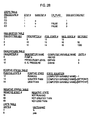
- Figure 2B shows partial contents of a Steps Table which stores procedure numbers, such as EO, step numbers, substep numbers, (DSS) Entities Keys and OR_Flags.
- a procedure includes steps and steps include substeps. Substeps can also include subsubsteps but are not shown in this example.
- the DSS Entities Keys of the Steps Table point to entries in the DSS Entities Table.
- the DSS Entities Table comprises a descriptor number, a positive state and a negative state, and a setpoint.
- the descriptor number points to an entry in the Descriptor Table.
- the Descriptor Table comprises a descriptor name, a computer variable name for the descriptor and a units number which points to a Units Table.
- the positive state and negative state number of the DSS Entities Table point to entries in the Positive States Table and Negative States Table respectively.
- the setpoint column in the DSS Entities Table comprises numbers.
- the Positive State Table comprises positive state numbers, positive states and state equations.
- the positive state number is pointed to by the positive state number in the DSS Entities Table and identifies a row of the Positive State Table.
- the Positive State is a description of the positive state of the represented logical state, such as "Greater Than” or "Less Than", and is used for display purposes only.
- the State Equation identifies a form of the equation to be evaluated by defining each component of the equation, such as [Computer Variable Name] ⁇ [Setpoint] for example.
- the Negative State Table comprises Negative state numbers and Negative states.
- the negative state number is pointed to by the negative state number in the DSS Entities Table.
- the Negative State is a description of the negative state of the represented logical state, such as "Not Greater Than” or “Not Less Than”, and is used for display purposes only.
- the Units Table comprises units numbers and units name.
- the unit number is pointed to by the units number in the Descriptors Table.
- the Units Name is the units of the descriptor, such as psia for example, and are used for displaying purposes only.
- procedure E0, step 1 includes only three substeps a, b and c.
- Each of the substeps is an equation which are formed according to the contents stored in the other Tables.
- Each of the equations formed represent the condition of procedure E0, steps 1, substeps a, b and c respectively, shown in Figure 2A.
- the DSS Entities Key points to the DSS Entities Table which describes the relationship between each of the tables shown in Figure 2B to form the equations.
- a relational database management system 112 such as INGRESTM or ORICLE which are commercially available software systems, aids in the management of the information stored in the tables shown in Figure 2B.
- INGRESTM automatically provides four functions: 1) accept data and instructions from users; 2) retrieve information from the database; 3) update the database; and 4) format and output data to users. The availability of these functions reduces the coding effort required to manipulate a database.
- a person having ordinary skill in the art familiar with INGRES, UNIX and the C Language can provide appropriate software to use such functions to, for example, access, load and maintain a database such as shown in Figure 2B.
- INGRESTM helps to store and retrieve all the data required to generate a procedure, such as entry conditions, steps, substeps, descriptors, states and setpoints.
- Facility specialists use INGRESTM functions to store the procedural information in tables as described above and to specify the linked association or relationship between the tables as shown in Figure 2A.
- INGRESTM also provide other functions, such as viewing the current contents of the database, searching for specific data, making modifications to the data, deleting old data and adding new data.
- Various reporting options are available in INGRESTM to produce hardcopy reports of the database content.
- INGRESTM In addition to automatically providing the ability to retrieve, append, modify and delete data, INGRESTM also ensures data integrity. Data consistency is automatically protected during updates and an ongoing journal of all database activity is kept so that the database can be fully restored to it original state in case of a software or hardware failure. Validation checks by INGRESTM also protect the integrity of the database. Every update can be checked against a set of constraints that are set by system design specialists to ensure valid entries.
- This invention has three main software modules: 1) Maintain the relational database 114 (Maintain 114); 2) Build and Maintain Procedures 116 (Build 116); and 3) Process Procedures 118 (Process 118). These three software modules assist a facility operator in generating procedures and executing the procedures by converting what is stored in a database into executable software equations. Each of these three software modules are preferably written in the C language with embedded SQL (Standard Query Language).
- the three software modules are each independently executable programs. Maintain 114 and Build 116 preferably run off-line which means that these modules are executing before actual execution of the system software.
- Process 118 is executed on-line when the actual monitoring of the nuclear power facility begins.
- Process 118 utilizes commercially available UNIXTM utilities such as lex 122 and yacc 124 for formulating and compiling equations from the data stored in the relational database and for executing the equations at run-time.
- Lex 122 and yacc 124 are instrumental in compiling the equations at run-time rather than compiling the equations when the system source code is compiled.
- Lex 122 is a generator of lexical analyzers
- yacc 124 is a compiler writing system.
- the software modules also utilize a Windowing system 126, such as the commercially available Windows 4GL for off-line data inputting and outputting and, Open Windows for executing the process procedures module 118.
- Windows 4GL assists a facility specialist in Build 116 to communicate with the INGRESTM relational database.
- Windows 4GL communicates with SunOS 108 to permit facility specialists to build user interface forms to input data into and retrieve data from the relational database.
- Windows 4GL facilitates window management for programmers by providing visual editors which allow programmers to design and test forms and menus interactively, generating any number of windows within an application, interactively place fields, buttons, bitmaps and other visual elements in windows, and other functions.
- Maintain 114 uses UNIXTM scripts to update the database.
- Software module Maintain 114 is a utility to assist a database manager in performing routine maintenance operations on the database and the disk storage device 110, such as journaling and checkpointing, to ensure the integrity of the database stored on disk storage device 110 and whether the database is up-to-date. Maintain 116 does not verify the entries in the relational database but ensures that the database itself is current and not changed by a person having unauthorized access. If the database is not correctly maintained, the execution of complex operating procedures will likewise be inaccurate. Therefore, the accuracy of the database is an essential part of a proper execution of the system.
- One having ordinary skill in the art can utilize database maintenance functions previously mentioned and available through UNIX scripts using INGRES commands to perform the Maintain 114 operations.
- Software module Build 116 is a facility to load procedural information in the relational database so that it can be executed in Process 118.
- the procedural information to be entered includes, for example, step numbers, substep numbers, descriptor names, computer variable names, setpoints, units, etc, as shown in Figure 2B.
- the facility specialists use a series of forms which are displayed by the Windowing system 126. The forms will organize procedural information so that similar information will be part of the same form.
- One having ordinary skill in the art can load procedural information into the database using commercially available functions as previously discussed and executable or available through the INGRES.
- Software module Process 118 represents the on-line processing function of the COMPRO system. Process 118 encompasses generating and executing complex operating procedure equations to monitor a nuclear power facility.
- the diagram in Figure 3 illustrates software modules of Process 118 for generating executable software equations.
- Data structure builder 200 generates procedural information 202 from the relational database from disk storage device 110 via the relational database management system 112.
- Data structure builder 200 essentially copies the database contents stored on disk storage device 110 into local memory.
- the reason for copying the database contents into local memory is to reduce the time it would take to traverse the database stored on disk storage device 110.
- Data structure builder 200 would not be needed if the INGRES relational database had faster on-line accessing capabilities.
- the C data structures are easily traversed so the system will not be slowed. Therefore, local memory is defined by using and the data from the relational database is stored in C language data structures, such as "struct" and pointer or "char 'pointer” for example, which implement table type structures and maintain the interrelationship between the tables while providing memory for storing procedural information. That is, the table arrangement of Figure 2B used for relational database storage is maintained in the local memory.
- the database tables and the associative information, such as interrelationships among the tables, are read from disk storage device 110 using commands, for example SELECT, provided by SQL and INGRES. Both the tables and the relationships between the tables stored in the relational database are predefined by facility specialists according to each application. These tables are read into local memory by utilizing C data structure constructs. For example, a facility specialist would create and define a table, such as the Steps Table shown in Figure 2B, by creating and labelling each of the columns and inserting the appropriate data into each row, column.
- a facility specialist would create and define a table, such as the Steps Table shown in Figure 2B, by creating and labelling each of the columns and inserting the appropriate data into each row, column.
- One having ordinary skill in the art can examine the Steps Table and make a corresponding C language data structure to hold this information.
- Equation Builder 204 then builds each of the equations or mathematical expressions as shown in the flowchart illustrated in Figure 4.
- the Equation Builder 204 as shown in Figure 4 builds each of the equations which were previously hard-coded into the system software.
- a composite equation is comprised of singular equations. For each of the conditions (substeps a, b and c) shown in Figure 2A for procedure E0, step 1 a corresponding singular equation is made by concatenating a descriptor, a logical state and, if needed, one or more setpoints together.
- a descriptor represents one of the many valves, pumps, generators, trip breakers, or similar physical features of a nuclear power plant which is stored in the relational database.
- the descriptor for the condition shown in Figure 2A, procedure E0, step 1, substep a is "Pump A”.
- the descriptor for the conditions of procedure E0, step 1, substeps b and c are "Pressurizer Level” and “Steam Generator (S.G.) Pressure" respectively.
- the descriptors are stored in a Descriptors Table C data structure under the Descriptor Name.
- the Descriptors Table C data structure is pointed to by the Descriptor number stored in the DSS Entities Table C data structure, which is pointed to by the DSS Entities Key of the Steps Table C data structure.
- the Computer Variable Name stored in the Descriptors Table C data structure represents a unique identifier for a sensor value obtained when the facility sensors are scanned.
- the logical state for each of the equations represents how the descriptor relates to setpoint values.
- the logical state for procedure E0, step 1, substep b shown in Figure 2A is "greater than”.
- the logical state for Procedure E0, step 1, substep a is either true or false because the pump will either be running or not running, which is determined by only examining the on/off switch sensor of Pump A.
- the Positive States Table data structure shown in Figure 2B stores a state equation for each of the equations.
- the state equation defines the form of the equation by defining what components are being compared and a logical operator used to perform the logical comparison between the components, such as " ⁇ " for example.
- a logical operator used to perform the logical comparison between the components, such as " ⁇ " for example.
- an example of the logical state (State Equation) of procedure E0, step 1, substep b is a ">" in contrast to procedure E0, step 1, substep c which is a " ⁇ " logical state.
- the setpoint value of the DSS Entities Table is a number representing a condition at which the corresponding descriptor will either be true or false.
- the setpoint values for procedure E0, step 1, substeps b and c and are stored in the DSS Entities Table C data structure as 50 and 1000 respectively, under Setpoint.
- Equation builder 204 begins by searching the C data structure 300 for each occurrence of an equation associated with a step and substep. For example, a pointer points to a C data structure "struct" table, such as the Steps Table shown in Figure 2B for example.
- the C data structure for the procedure number and step number are read and stored as variables.
- a label for the composite equation is generated 302 by Equation Builder 204.
- the first procedure number is read from the Steps Table C data structure.
- the procedure number is stored in a composite equation character string which is followed by a ":”.
- the step number is read from the Steps Table data structure, converted into a character string and stored after "E0:” in the composite equation character string.
- the next procedure and step number are read 304 from the C data structure and compared 306 to the variable procedure number and step number. If either the procedure or step number is different, then this would indicate the end of the composite equation.
- the composite equation would then be stored 308 in a file (not shown). This file, which will contain all singular and composite equations, will be sent to a parser and compiler.
- the composite character string will be set to C language "null" 310. If the procedure and step number point to the end of the Steps Table C data structure 312, as indicated by a C language construct, then the Equation Builder quits 314. Otherwise, the Equation Builder makes a label for the next composite equation 302.
- next procedure number and step number are the same 306, then the logical operator for the composite equation is read and stored in the composite character string 316.
- the OR_Flag entry stored in Steps Table C data structure for procedure E0, step 1, substep a is read. If the result is a C language "null”, then nothing is appended to the end of the composite equation character string. If the result is true, the character symbol ":" (OR logical operation) is appended to the end of the composite equation character string. If the result is false, the character symbol "&" (AND logical operation) is appended to the end of the composite equation character string. In this example, the OR_Flag is null. None is appended to the end of the composite character string at this time.
- a label is generated for a singular equation 318.
- a pointer will point to the entries in the Steps Table C data structure which indicates an equation representing procedure E0, step 1, substep a.
- a label for a singular equation is generated 318 by reading the procedure number character string "EO” from the C data structure and stored it in the variable character string. "EO” is also appended to the end of the composite equation character string.
- a “:” is then entered in the next available space of the variable character string and composite equation character string.
- the step number is read from the Steps Table data structure, converted into characters and stored next in the next locations in the variable and composite character strings. Another ":” is inserted in the next location in the variable and composite equation character strings.
- the substep number is then read from the Steps Table data structure and stored in the variable and composite equation character strings.
- a descriptor, logical operator and one or more setpoints are concatenated together to form a singular equation 320.
- a positive state number is read from the DSS Entities Table C data structure based on the DSS Entities Key pointer and value.
- the positive state number in the DSS Entities Table C data structure is a pointer to the value of the positive state number stored in Positive States Table.
- the state equation is read into a character string. If the state equation character string contains [Computer Variable Name], the Computer Variable Name is read from the Descriptors Table C data structure and substituted for (Computer Variable Name].
- the state equation contains [Setpoint]
- the setpoint is read from the DSS Entities Table C data structure and substituted for [Setpoint].
- the state equation character string is then stored in the variable character string. This concatenated character string equation, therefore, contains a descriptor, logical operator and setpoint.
- the Computer Variable Name is read by reading the DSS Entities Key which is a pointer to a DSS Entities Key value in the DSS Entities Table. This pointer will point to the first set of entries in the DSS Entities Table. Based on the DSS Entities Key pointer and value, the descriptor number stored in the DSS Entities Table C data structure is read. The descriptor number in the DSS Entities Table data structure is a pointer to the value of the descriptor number stored in the Descriptor Table C data structure. Based on the Descriptor number pointer and value, a computer variable name stored in the Descriptor Table C data structure is read and substituted into the state equation character string.
- the setpoint value is read from the DSS Entities Table C data structure based on the DSS Entities Key pointer and value.
- the setpoint values for procedure E0, steps 1, substeps a and b, are 50 and 1000 respectively. These values will be converted into character strings and substituted into the state equation character string.
- variable character string Once the state equation character string is stored in the variable character string, the result is an equation for procedure E0, step 1, substep a.
- the concatenated equation in the variable character string is then stored 320 in a file (not shown) which will be sent to a compiler and a parser once all the equations have been generated.
- the functions performed by the compiler, the parser, yacc, and lex will be described later in this application.
- variable character string is stored in a file 320
- next procedure and step number are read and compared to the prior procedure and step number 304. If the result of the comparison is true, then all of the singular equations for the procedure/step have been generated. Therefore, the composite equation is then stored in the file 308 and set to "null" 310.
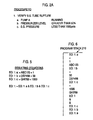
- Equations representing procedure E0, step 1, substeps b and c are generated in the same manner as described above for substep a. In fact, all the singular and composite equations for each entry condition, procedure/step and parallel information are generated by the same method described above. The resulting singular and composite equations character strings for procedure E0, step 1 are shown in Figure 5.
- the result of each of the singular equations will be either true or false. This result will aid in determining whether a nuclear power facility is operating correctly.
- the evaluation of the composite equation shown in Figure 5 represents whether a steam generator tube has ruptured for the procedure describe in Figure 2A. If the result of the evaluation is true, this may signal a warning or violation message indicating what procedure to execute in order to correct the rupturing of the steam generator, such as shut off the pump or decrease the pressure level.
- Equation Builder 204 After each equation is built by equation builder 204, compiler 206 begins reading the file containing all the singular and composite equations character strings from Equation Builder 204. Parser 208 together with the powerful UNIXTM utilities lex 122 and yacc 124, compiles stacks 210 and tables 214 and 216. Parser 208 parses the equations which have been generated as strings by equation builder 204. The Parser 208 can handle both simple and sophisticated expressions. One having ordinary skill in the art can use commercially available UNIX utilities lex and yacc to parse and compile strings.
- the other UNIXTM utility yacc 124 provides a general tool for defining the rules and structure for an input stream or user-defined equations. Lex 122 is a low level routine used by yacc 124 to select the tokens from the user-defined equations 202 to organize them according to the input structure rules. Thus, when yacc 124 recognizes the rules in system-defined equations, the compiler 206 calls the lex 122 and yacc 124 based functions to generate the program stack 210, entry point table 214 and symbol table 216.
- the compiler keeps using parser 208, lex 122 and yacc 124 to operate on each respective equation. Note that the character string equations generated by equation builder 204 have no predetermined content, but are determined by the system designer of the nuclear power plant. The compiler follows the order introduced by the predefined logic, which is a key to the system flexibility.
- the compiler using conventional operations, creates a symbol table 216, a program stack 210 and an entry point table.
- the program stack 210 for the singular equation and the composite equation of Figure 5 is shown in Figure 6.
- the first entry for an equation is the label for the location where the result is stored.
- the logical operator is the remaining two entries are the operands.
- the program stack 210 contains executable instructions referred to here as pseudo-instructions and operand names.
- pseudo-instructions include (i) operators or requests to execute a set of primitives consisting of operators, as well as any library functions; (ii) requests to run other user defined program segments; and (iii) requests to push addresses or values onto a context stack 212 from the symbol table.
- the entry point table 214 contains pointers to the program stack at the end of compilation.
- the entry point pointers point to parallel information equations, entry condition equations and procedure/step equations.
- the symbol table 216 contains pointers to temporary variables, constants and built-in functions.
- the process procedures 118 shown in Figures 1 and 7 executes and evaluates the equations stored on the program stack 210 in accordance with the context stack 212, the entry point table 214 and the symbol table 216.
- Figure 7 is a flowchart of the on-line processing executed by software module Process 118.
- Data structure Builder 200 accesses 400 and copies the relational database stored on the disk storage device 110 to local memory 402.
- Equation Builder 204 generates 404 all of the logic equations through the method illustrated in Figures 3 and 4.
- Entry condition equations are evaluated first 406 by determining whether each of the entry condition singular equations and composite equations are true or false.
- the evaluation or execution of the equations is performed using the entry point table 214, the program stack 210, the context (data) stack 212 and the symbol table 216.
- the execution starts with the entry point table 214 which points to the starting point for entry condition equations.
- the equations are evaluated or executed, for example, using a conventional reverse polish notation type stack execution method.
- the program stack as illustrated in Fig. 6 is used to execute singular equations EO: 1:a, EO: 1:b and EO: 1:c and the composite equation illustrated in Fig. 5.
- the symbol table 216 which is a cross reference from the variable name to the storage location for that variable is used to obtain the actual values of the variables for execution and to store the results.
- the data stack 212 is used to store retrieved variables and intermediate results.
- procedure E0, step 1 will be executed because equations a, b and c follow procedure header EO step 1 on the program stack 210.
- procedure E0, step 1 may call for turning off pump A and if so, a message is sent to the plant operator via a display screen is displayed telling the operator to turn off pump A.
- procedure E1 would be executed.
- the procedure and step number are set 412, all of the equations associated with the procedure are evaluated 414.
- the evaluation procedure is the same as described previously with respect to evaluating entry condition equations.
- the current procedure and step number are determined 416 to indicate what step of what procedure is currently being executed. This determination is made by referring to the current procedure and step number stored in local memory.
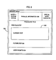
- the action steps of the procedure are displayed 418 in display device 500 at the current step box 502 as illustrated in Figure 8.
- Text displayed in the current step box 502 is the expected action or response by the facility operator.
- Each step contains a high-level statement which describes the task to be performed. If the high-level task (step) requires multiple actions, then subtasks (substeps) are specified. Following each task or subtask, the expected response or result is given. Action steps are written so that the facility operator can proceed directly down the list. This display contains all the expected conditions, and checks required to accomplish the stated purpose of the procedure, or what course of action a facility operator should perform.
- a prompt is displayed 418 which indicates what recommended course of action the facility operator should take. Prompts are displayed as shown in Figure 8 at the location of user prompts 504. The prompt will be continuously displayed until the operator addresses the prompt 424.
- the step is checked to determine whether the expected response was obtained. If the expected response is not obtained, then a violation exists and the output device 106 displays contingency instructions 422 in the current step box 502 shown in Figure 8. The display also displays in the current step box 502 whether the recommended response chosen by the facility operator was not obtained. Almost all action steps displayed in current step box 502 contain some contingency action statement. If a contingency is not provided, then the system proceeds to the next step or substep that is displayed at future step 506 shown in Figure 8, and the current procedure equations are again evaluated 414.
- a user response is required before the system will advance to the next step or procedure.
- a prompt is displayed at user prompts 504 shown in Figure 8 which recommends the step to execute 418 or 422 to which the facility operator can respond.
- the response is checked to determine whether the operator wants to continue with the recommended course of action. If the facility operator desires to continue with the indicated course of action, for example, the next relevant step or part of the procedure, as displayed by the prompt 418 or 422, the displayed procedure and step number are set to the indicated values 412. If the facility operator chooses to quit the monitoring of the current procedure 428, the program returns to evaluating and monitoring entry conditions 406.
- Parallel information equations are concurrently evaluated 430 with the evaluation and monitoring of the current procedure step equations. Once again, evaluation is performed as previously discussed with respect to evaluating entry condition equations.
- Parallel information includes, for example, Notes, Cautions, Foldout Pages, and parameter and component state changes which have been initiated but not completed upon exiting the currently active procedure step.
- Parallel information also includes global or continuously controlled parameters which need to be monitored for more than a single procedure step, for example, maintaining a steam generator level at a certain value.
- Parallel information equations are stored in the relational database and generated in a similar manner as the procedure/step equations shown in Figures 2A and 2B.
- the procedure and step number will be determined 432 in a similar manner as described above so that parallel information that is executed is associated with the currently executing step. Some parallel information is global and will always be evaluated. If a completed procedure step (or substep), a Note or Caution involves a parameter which should be continuously controlled 432, the system will monitor that parameter 434 until any of the associated equations is evaluated to false.
- the result of the evaluation of the parallel information equations is monitored 434 to determine if a violation has occurred 436. If all of the associated equations for a procedure in the parallel information are true, then a violation has occurred for that procedure. If a violation has occurred in the parallel information 436, an alert message is issued to an operator at parallel information 506 shown in Figure 8 and a prompt is displayed 438 at user prompts 504 which gives the recommended course of action the operator should take. The evaluation of the parallel information equations will continue 430 despite the violation after the prompt is displayed 438 at user prompts 504 shown in Figure 8.
- the facility operator will have complete control over the operation of the COMPRO system.
- the system will not advance to the next step or procedure for any reason without the concurrence by the facility operator.
- the procedure/step and parallel information loops are executing concurrently. Prompts are displayed 418, 422 and 440 which indicate the corrective procedure and step to execute.
- the system will wait for a facility operator response; however, the procedure/step and parallel information loops will continue to execute in parallel. Only after the facility operator responds to the displayed prompt 424, 426 at user prompt 504 shown in Figure 8, will the system advance to the next step or procedure. If the operator quits the procedure, the procedure and parallel information monitoring is halted 428 and the system returns to evaluating and monitoring the entry condition equations for a system violation 406.
Abstract
Description
- This invention generally relates to a method for generating and executing complex COMputerized PROcedures (COMPRO) which monitor the operation of a nuclear power facility and, more particularly, for generating equations representing conditions or states of the facility and executing the equations to determine whether the facility is operating within the design conditions and whether an emergency exists.
- COMPRO is a computerized information and control system primarily intended to be used to assist facility operators in monitoring and controlling the execution of plant procedures, including for example emergency operating, normal operating, abnormal operating and alarm responses. COMPRO allows facility operators to access and follow procedures in an easy and logical manner. At the same time, the COMPRO system provides the facility operators with parallel information to allow them to assess the overall status of the process or facility. COMPRO may be used for all types of plant operating procedures. Most plant operating procedures are well suited for automation since a computer can easily monitor many parameters concurrently. By presenting information in parallel, COMPRO helps plant operators to see where they are with respect to the overall plant response.
- Formal written plant operating procedures under either normal or emergency conditions for a nuclear power plant are developed well in advance by experienced specialists. These procedures are not only intended to guide a facility operator along a recommended course of action but also to detect anomalous conditions and to recommend changes in the normal course of action to deal with these anomalies.
- COMPRO or the interactive computer based monitoring of the execution of complex operating procedures is well established and has resulted in issued patents, for example, U.S. Patent Nos. 4,803,039, 4,815,014 and 5,068,080. After the design of the basic system to execute complex operating procedures, the subsequent patents have focused on enhancements to the basic system and have not addressed the fundamental software structure of the basic system.
- The design of the basic software had system parameters (valves, pumps, generators) and conditions hard-coded into the software. For example, feed water valves may operate above a certain flow condition, such as 100 feet/second. This condition was hard-coded into the system software, for example as "If valve- input > 100 then valve-condition = True". The software was compiled resulting in executable source code explicitly including the decision making steps.
- However, if one parameter had to be changed, the system source code would also have to be changed and thus, would also require a recompilation of the source code for the entire system. The recompilation was costly because of the editing, testing, and verification and validation required in this type of implementation of the COMPRO system. Moreover, system designers had the arduous task of writing and maintaining potentially thousands of lines of computer code.
- It is an object of the present invention to build and execute equations at run-time to monitor the operation of a facility.
- It is another object of the present invention to modify conditions without recompiling the system source code.
- It is also an object of the present invention to use a relational database to store components of the equations and logical relationships between the equations and to use these relationships to generate equations.
- It is a further object of the present invention to generate composite and singular equations from a relational database which indicates the physical characteristics and conditions of a facility.
- It is another object of the present invention to monitor and sequence through a procedure by each of its steps, while concurrently monitoring parallel information which indicates the overall operation of the facility.
- It is also an object of the present invention to guide a facility operator in resolving any violations (either related to a step or a piece of parallel information).
- The above objects can be attained by a method which utilizes a relational database and management system to store procedure information including descriptors, logical states and setpoints. The descriptors, states and setpoints are concatenated together to form singular and composite equations which represent how sensor data will be evaluated. Once the equations are generated, they are individually parsed and compiled to form an executable representation. Compiled entry condition equations are evaluated and monitored to determine whether a violation of the facility has occurred. Once a violation occurs, a predetermined course of action or a procedure is recommended by COMPRO which is displayed to a facility operator. The system continuously monitors and evaluates equations and will only proceed to the next procedure/step when the facility operator responds to a prompt.
- Components of the procedural information equations act as input to the system program instead of residing as code in the program. Thus, changes can be made to the equations without requiring changes to the software code. Isolating all procedural information, including components of the equations, which is subject to change from the software code, will eliminate the need for modifying the source code when procedural information or setpoint values are changed.
- The advantages to this system are clear. This invention reduces the overall complexity of the system by storing procedural knowledge and setpoints in a relational database. This facilitates system maintenance since it is far easier to modify procedural information stored in a relational database than source code. This invention also facilitates the customizing of a user interface, and permits direct application to foreign languages since character strings in the database may be entered in any language.
- Figure 1 is a block diagram of the system according to the present invention;
- Figure 2A shows one of the many procedure steps implemented in the COMPRO system;
- Figure 2B shows a procedure step stored as a series of tables in the relational database;
- Figure 3 is a block diagram of the generation and execution of equations;
- Figure 4 is a flowchart illustrating the operation of an equation builder;
- Figure 5 shows examples of character strings of concatenated singular equations and a concatenated composite equation;
- Figure 6 shows a program stack;
- Figure 7 is a block diagram of the flow of the generating and execution of complex operating procedures; and
- Figure 8 illustrates where information is displayed on a display screen.
- An overview of the system hardware and software modules is shown in Figure 1. The software modules are preferably executed on a commercially available Sun Micro Systems workstation (Sun-3 or Sun-4 workstation), shown as
CPU 100.User input 102 is input toCPU 100 byinput devices 104 such as a mouse, keyboard or a touch display which is able to sense or detect a human touch.CPU 100 outputs to outputdevices 106 such as a printer or a display. The operating system ofCPU 100 is preferably the SUNOS@ 108 (version 3.0.3).CPU 100 stores procedural information in a relational database on adisk storage device 110 using a relationaldatabase management system 112. - A relational database is a collection of related information. The relational database in accordance with the present invention includes a series of tables which are logically interrelated. An example is shown in Figure 2A of one of a plurality of procedures comprising a plurality of steps, each step including a plurality of equations which are stored in the relational database. Figure 2B shows
step 1 of Procedure EO of Figure 2A stored as a series of tables in the relational database. - In Figure 2A,
step 1 of Procedure EO is evaluated to verify whether a steam generator tube has ruptured. Substep a ofProcedure EO step 1 first examines the pump A running indicator to see if pump A is running. Next, substep b ofProcedure EO step 1 examines a pressurizer sensor which indicates a pressurizer level of the steam generator to determine whether it is greater than 50%. Finally, the steam generator pressure sensor is read to see if the pressure is less than 1000 psia.Step 1 of Procedure EO indicates that the steam generator tube will have ruptured if a) Pump A is running; and b) the pressurizer level is greater than 50%; and c) the steam generator pressure is less than 1000 psia. That is, the tube will have ruptured only if all equations are true. COMPRO then provides a facility operator with steps which are displayed on theoutput device 106 and the operator can perform the steps to correct the rupture of the steam generator tube, such as stopping Pump A from running. - Figure 2B shows partial contents of a Steps Table which stores procedure numbers, such as EO, step numbers, substep numbers, (DSS) Entities Keys and OR_Flags. A procedure includes steps and steps include substeps. Substeps can also include subsubsteps but are not shown in this example.
- The DSS Entities Keys of the Steps Table, as illustrated in Figure 2B, point to entries in the DSS Entities Table. The DSS Entities Table comprises a descriptor number, a positive state and a negative state, and a setpoint. The descriptor number points to an entry in the Descriptor Table.
- The Descriptor Table comprises a descriptor name, a computer variable name for the descriptor and a units number which points to a Units Table. The positive state and negative state number of the DSS Entities Table point to entries in the Positive States Table and Negative States Table respectively. The setpoint column in the DSS Entities Table comprises numbers.
- The Positive State Table comprises positive state numbers, positive states and state equations. The positive state number is pointed to by the positive state number in the DSS Entities Table and identifies a row of the Positive State Table. The Positive State is a description of the positive state of the represented logical state, such as "Greater Than" or "Less Than", and is used for display purposes only. The State Equation identifies a form of the equation to be evaluated by defining each component of the equation, such as [Computer Variable Name] < [Setpoint] for example.
- The Negative State Table comprises Negative state numbers and Negative states. The negative state number is pointed to by the negative state number in the DSS Entities Table. The Negative State is a description of the negative state of the represented logical state, such as "Not Greater Than" or "Not Less Than", and is used for display purposes only.
- The Units Table comprises units numbers and units name. The unit number is pointed to by the units number in the Descriptors Table. The Units Name is the units of the descriptor, such as psia for example, and are used for displaying purposes only.
- According to the Steps table, procedure E0,
step 1, includes only three substeps a, b and c. Each of the substeps is an equation which are formed according to the contents stored in the other Tables. Each of the equations formed represent the condition of procedure E0, steps 1, substeps a, b and c respectively, shown in Figure 2A. The DSS Entities Key points to the DSS Entities Table which describes the relationship between each of the tables shown in Figure 2B to form the equations. - A relational
database management system 112, such as INGRES™ or ORICLE which are commercially available software systems, aids in the management of the information stored in the tables shown in Figure 2B. INGRES™ automatically provides four functions: 1) accept data and instructions from users; 2) retrieve information from the database; 3) update the database; and 4) format and output data to users. The availability of these functions reduces the coding effort required to manipulate a database. A person having ordinary skill in the art familiar with INGRES, UNIX and the C Language can provide appropriate software to use such functions to, for example, access, load and maintain a database such as shown in Figure 2B. - INGRES™ helps to store and retrieve all the data required to generate a procedure, such as entry conditions, steps, substeps, descriptors, states and setpoints. Facility specialists use INGRES™ functions to store the procedural information in tables as described above and to specify the linked association or relationship between the tables as shown in Figure 2A. INGRES™ also provide other functions, such as viewing the current contents of the database, searching for specific data, making modifications to the data, deleting old data and adding new data. Various reporting options are available in INGRES™ to produce hardcopy reports of the database content.
- In addition to automatically providing the ability to retrieve, append, modify and delete data, INGRES™ also ensures data integrity. Data consistency is automatically protected during updates and an ongoing journal of all database activity is kept so that the database can be fully restored to it original state in case of a software or hardware failure. Validation checks by INGRES™ also protect the integrity of the database. Every update can be checked against a set of constraints that are set by system design specialists to ensure valid entries.
- This invention, as illustrated in Figure 1, has three main software modules: 1) Maintain the relational database 114 (Maintain 114); 2) Build and Maintain Procedures 116 (Build 116); and 3) Process Procedures 118 (Process 118). These three software modules assist a facility operator in generating procedures and executing the procedures by converting what is stored in a database into executable software equations. Each of these three software modules are preferably written in the C language with embedded SQL (Standard Query Language).
- The three software modules are each independently executable programs. Maintain 114 and
Build 116 preferably run off-line which means that these modules are executing before actual execution of the system software.Process 118 is executed on-line when the actual monitoring of the nuclear power facility begins.Process 118 utilizes commercially available UNIX™ utilities such aslex 122 andyacc 124 for formulating and compiling equations from the data stored in the relational database and for executing the equations at run-time.Lex 122 andyacc 124 are instrumental in compiling the equations at run-time rather than compiling the equations when the system source code is compiled.Lex 122 is a generator of lexical analyzers, andyacc 124 is a compiler writing system. Those of ordinary skill in the art understand how to use these utilities to parse and compile strings. - The software modules also utilize a
Windowing system 126, such as the commercially available Windows 4GL for off-line data inputting and outputting and, Open Windows for executing theprocess procedures module 118. Windows 4GL assists a facility specialist inBuild 116 to communicate with the INGRES™ relational database. Windows 4GL communicates withSunOS 108 to permit facility specialists to build user interface forms to input data into and retrieve data from the relational database. Windows 4GL facilitates window management for programmers by providing visual editors which allow programmers to design and test forms and menus interactively, generating any number of windows within an application, interactively place fields, buttons, bitmaps and other visual elements in windows, and other functions. Maintain 114 uses UNIX™ scripts to update the database. - Software module Maintain 114 is a utility to assist a database manager in performing routine maintenance operations on the database and the
disk storage device 110, such as journaling and checkpointing, to ensure the integrity of the database stored ondisk storage device 110 and whether the database is up-to-date. Maintain 116 does not verify the entries in the relational database but ensures that the database itself is current and not changed by a person having unauthorized access. If the database is not correctly maintained, the execution of complex operating procedures will likewise be inaccurate. Therefore, the accuracy of the database is an essential part of a proper execution of the system. One having ordinary skill in the art can utilize database maintenance functions previously mentioned and available through UNIX scripts using INGRES commands to perform the Maintain 114 operations. -
Software module Build 116 is a facility to load procedural information in the relational database so that it can be executed inProcess 118. The procedural information to be entered includes, for example, step numbers, substep numbers, descriptor names, computer variable names, setpoints, units, etc, as shown in Figure 2B. The facility specialists use a series of forms which are displayed by theWindowing system 126. The forms will organize procedural information so that similar information will be part of the same form. One having ordinary skill in the art can load procedural information into the database using commercially available functions as previously discussed and executable or available through the INGRES. -
Software module Process 118 represents the on-line processing function of the COMPRO system.Process 118 encompasses generating and executing complex operating procedure equations to monitor a nuclear power facility. The diagram in Figure 3 illustrates software modules ofProcess 118 for generating executable software equations.Data structure builder 200 generatesprocedural information 202 from the relational database fromdisk storage device 110 via the relationaldatabase management system 112. -
Data structure builder 200 essentially copies the database contents stored ondisk storage device 110 into local memory. The reason for copying the database contents into local memory is to reduce the time it would take to traverse the database stored ondisk storage device 110.Data structure builder 200 would not be needed if the INGRES relational database had faster on-line accessing capabilities. The C data structures are easily traversed so the system will not be slowed. Therefore, local memory is defined by using and the data from the relational database is stored in C language data structures, such as "struct" and pointer or "char 'pointer" for example, which implement table type structures and maintain the interrelationship between the tables while providing memory for storing procedural information. That is, the table arrangement of Figure 2B used for relational database storage is maintained in the local memory. - The database tables and the associative information, such as interrelationships among the tables, are read from
disk storage device 110 using commands, for example SELECT, provided by SQL and INGRES. Both the tables and the relationships between the tables stored in the relational database are predefined by facility specialists according to each application. These tables are read into local memory by utilizing C data structure constructs. For example, a facility specialist would create and define a table, such as the Steps Table shown in Figure 2B, by creating and labelling each of the columns and inserting the appropriate data into each row, column. One having ordinary skill in the art can examine the Steps Table and make a corresponding C language data structure to hold this information. - This same process would be repeated for every table stored in the relational database. Then, the contents of the table stored in the
disk storage device 110 are read using the SQL command SELECT, for example, and stored into the corresponding C data structure. Therefore, one having ordinary skill in the art can define C data structures and C/UNIX software with facilities provided by INGRES and SQL to copy the data from the database stored ondisk storage device 110 into local memory. Any place in the table where there is no entry, a zero or a C language "null" will be entered or defaulted to initially when theProcess 118 module begins executing. - After the
data structure builder 200 stores the database contents in local memory,Equation Builder 204 then builds each of the equations or mathematical expressions as shown in the flowchart illustrated in Figure 4. TheEquation Builder 204 as shown in Figure 4 builds each of the equations which were previously hard-coded into the system software. - There are two types of equations: composite equations and singular equations. A composite equation is comprised of singular equations. For each of the conditions (substeps a, b and c) shown in Figure 2A for procedure E0, step 1 a corresponding singular equation is made by concatenating a descriptor, a logical state and, if needed, one or more setpoints together.
- A descriptor represents one of the many valves, pumps, generators, trip breakers, or similar physical features of a nuclear power plant which is stored in the relational database. For example, the descriptor for the condition shown in Figure 2A, procedure E0,
step 1, substep a, is "Pump A". Similarly the descriptor for the conditions of procedure E0,step 1, substeps b and c are "Pressurizer Level" and "Steam Generator (S.G.) Pressure" respectively. The descriptors are stored in a Descriptors Table C data structure under the Descriptor Name. The Descriptors Table C data structure is pointed to by the Descriptor number stored in the DSS Entities Table C data structure, which is pointed to by the DSS Entities Key of the Steps Table C data structure. The Computer Variable Name stored in the Descriptors Table C data structure represents a unique identifier for a sensor value obtained when the facility sensors are scanned. - The logical state for each of the equations represents how the descriptor relates to setpoint values. The logical state can be for example, <, >, =, AND and NOR, etc. The logical state for procedure E0,
step 1, substep b shown in Figure 2A is "greater than". The logical state for Procedure E0,step 1, substep a is either true or false because the pump will either be running or not running, which is determined by only examining the on/off switch sensor of Pump A. - The Positive States Table data structure shown in Figure 2B, stores a state equation for each of the equations. The state equation defines the form of the equation by defining what components are being compared and a logical operator used to perform the logical comparison between the components, such as "<" for example. As shown in Figure 2B, an example of the logical state (State Equation) of procedure E0,
step 1, substep b is a ">" in contrast to procedure E0,step 1, substep c which is a "<" logical state. - The setpoint value of the DSS Entities Table is a number representing a condition at which the corresponding descriptor will either be true or false. As shown in Figure 2A, the setpoint values for procedure E0,
step 1, substeps b and c and are stored in the DSS Entities Table C data structure as 50 and 1000 respectively, under Setpoint. -
Equation builder 204 begins by searching theC data structure 300 for each occurrence of an equation associated with a step and substep. For example, a pointer points to a C data structure "struct" table, such as the Steps Table shown in Figure 2B for example. The C data structure for the procedure number and step number are read and stored as variables. - A label for the composite equation is generated 302 by
Equation Builder 204. For example, the first procedure number is read from the Steps Table C data structure. The procedure number is stored in a composite equation character string which is followed by a ":". The step number is read from the Steps Table data structure, converted into a character string and stored after "E0:" in the composite equation character string. A ": = " is inserted after the step number in the composite equation character string, giving "E0: 1:a: = " where E0:1 :a is a label which will store the result of the equation. - The next procedure and step number are read 304 from the C data structure and compared 306 to the variable procedure number and step number. If either the procedure or step number is different, then this would indicate the end of the composite equation. The composite equation would then be stored 308 in a file (not shown). This file, which will contain all singular and composite equations, will be sent to a parser and compiler. The composite character string will be set to C language "null" 310. If the procedure and step number point to the end of the Steps Table
C data structure 312, as indicated by a C language construct, then the Equation Builder quits 314. Otherwise, the Equation Builder makes a label for the nextcomposite equation 302. - If the next procedure number and step number are the same 306, then the logical operator for the composite equation is read and stored in the
composite character string 316. For example, the OR_Flag entry stored in Steps Table C data structure for procedure E0,step 1, substep a is read. If the result is a C language "null", then nothing is appended to the end of the composite equation character string. If the result is true, the character symbol ":" (OR logical operation) is appended to the end of the composite equation character string. If the result is false, the character symbol "&" (AND logical operation) is appended to the end of the composite equation character string. In this example, the OR_Flag is null. Nothing is appended to the end of the composite character string at this time. - Next, a label is generated for a
singular equation 318. For example, a pointer will point to the entries in the Steps Table C data structure which indicates an equation representing procedure E0,step 1, substep a. A label for a singular equation is generated 318 by reading the procedure number character string "EO" from the C data structure and stored it in the variable character string. "EO" is also appended to the end of the composite equation character string. A ":" is then entered in the next available space of the variable character string and composite equation character string. The step number is read from the Steps Table data structure, converted into characters and stored next in the next locations in the variable and composite character strings. Another ":" is inserted in the next location in the variable and composite equation character strings. The substep number is then read from the Steps Table data structure and stored in the variable and composite equation character strings. A ": = " is stored in the variable equation character string after the substep number. Every equation will begin with a label comprised of the procedure and step number, and if not a composite equation, the substep number. The label is used by the parser and compiler to store the result of the equation. A ":" will separate each of these numbers represented as characters. - A descriptor, logical operator and one or more setpoints are concatenated together to form a
singular equation 320. For example, a positive state number, is read from the DSS Entities Table C data structure based on the DSS Entities Key pointer and value. The positive state number in the DSS Entities Table C data structure is a pointer to the value of the positive state number stored in Positive States Table. Based on the positive state number pointer and value, the state equation is read into a character string. If the state equation character string contains [Computer Variable Name], the Computer Variable Name is read from the Descriptors Table C data structure and substituted for (Computer Variable Name]. If the state equation contains [Setpoint], the setpoint is read from the DSS Entities Table C data structure and substituted for [Setpoint]. The state equation character string is then stored in the variable character string. This concatenated character string equation, therefore, contains a descriptor, logical operator and setpoint. - In this example, the Computer Variable Name is read by reading the DSS Entities Key which is a pointer to a DSS Entities Key value in the DSS Entities Table. This pointer will point to the first set of entries in the DSS Entities Table. Based on the DSS Entities Key pointer and value, the descriptor number stored in the DSS Entities Table C data structure is read. The descriptor number in the DSS Entities Table data structure is a pointer to the value of the descriptor number stored in the Descriptor Table C data structure. Based on the Descriptor number pointer and value, a computer variable name stored in the Descriptor Table C data structure is read and substituted into the state equation character string.
- In this example, the setpoint value is read from the DSS Entities Table C data structure based on the DSS Entities Key pointer and value. The setpoint values for procedure E0, steps 1, substeps a and b, are 50 and 1000 respectively. These values will be converted into character strings and substituted into the state equation character string.
- Once the state equation character string is stored in the variable character string, the result is an equation for procedure E0,
step 1, substep a. The concatenated equation in the variable character string is then stored 320 in a file (not shown) which will be sent to a compiler and a parser once all the equations have been generated. The functions performed by the compiler, the parser, yacc, and lex will be described later in this application. - After the variable character string is stored in a
file 320, the next procedure and step number are read and compared to the prior procedure andstep number 304. If the result of the comparison is true, then all of the singular equations for the procedure/step have been generated. Therefore, the composite equation is then stored in thefile 308 and set to "null" 310. - Equations representing procedure E0,
step 1, substeps b and c are generated in the same manner as described above for substep a. In fact, all the singular and composite equations for each entry condition, procedure/step and parallel information are generated by the same method described above. The resulting singular and composite equations character strings for procedure E0,step 1 are shown in Figure 5. - The result of each of the singular equations will be either true or false. This result will aid in determining whether a nuclear power facility is operating correctly. The evaluation of the composite equation shown in Figure 5 represents whether a steam generator tube has ruptured for the procedure describe in Figure 2A. If the result of the evaluation is true, this may signal a warning or violation message indicating what procedure to execute in order to correct the rupturing of the steam generator, such as shut off the pump or decrease the pressure level.
- After each equation is built by
equation builder 204,compiler 206 begins reading the file containing all the singular and composite equations character strings fromEquation Builder 204.Parser 208 together with the powerful UNIX™ utilities lex 122 andyacc 124, compilesstacks 210 and tables 214 and 216.Parser 208 parses the equations which have been generated as strings byequation builder 204. TheParser 208 can handle both simple and sophisticated expressions. One having ordinary skill in the art can use commercially available UNIX utilities lex and yacc to parse and compile strings. - The UNIX
™ utility lex 122 is used to define "tokens" recognized byparser 208. These tokens include the different types of allowable variables, operators (i.e., =, +, -, *, /, <, >, etc), functions and built-in constants. The other UNIX™ utility yacc 124 provides a general tool for defining the rules and structure for an input stream or user-defined equations.Lex 122 is a low level routine used by yacc 124 to select the tokens from the user-definedequations 202 to organize them according to the input structure rules. Thus, when yacc 124 recognizes the rules in system-defined equations, thecompiler 206 calls thelex 122 andyacc 124 based functions to generate theprogram stack 210, entry point table 214 and symbol table 216. - The compiler keeps using
parser 208,lex 122 and yacc 124 to operate on each respective equation. Note that the character string equations generated byequation builder 204 have no predetermined content, but are determined by the system designer of the nuclear power plant. The compiler follows the order introduced by the predefined logic, which is a key to the system flexibility. - The compiler, using conventional operations, creates a symbol table 216, a
program stack 210 and an entry point table. Theprogram stack 210 for the singular equation and the composite equation of Figure 5 is shown in Figure 6. As can be seen the first entry for an equation is the label for the location where the result is stored. Next is the logical operator and the remaining two entries are the operands. A similar arrangement exists for the composite equation, where all logical operators are given first followed by the operands as shown in Figure 6. - As discussed above, the
program stack 210 contains executable instructions referred to here as pseudo-instructions and operand names. These pseudo-instructions include (i) operators or requests to execute a set of primitives consisting of operators, as well as any library functions; (ii) requests to run other user defined program segments; and (iii) requests to push addresses or values onto acontext stack 212 from the symbol table. - The entry point table 214 contains pointers to the program stack at the end of compilation. The entry point pointers point to parallel information equations, entry condition equations and procedure/step equations. The symbol table 216 contains pointers to temporary variables, constants and built-in functions. The
process procedures 118 shown in Figures 1 and 7 executes and evaluates the equations stored on theprogram stack 210 in accordance with thecontext stack 212, the entry point table 214 and the symbol table 216. - Figure 7 is a flowchart of the on-line processing executed by
software module Process 118.Data structure Builder 200 accesses 400 and copies the relational database stored on thedisk storage device 110 tolocal memory 402.Equation Builder 204 generates 404 all of the logic equations through the method illustrated in Figures 3 and 4. - Entry condition equations are evaluated first 406 by determining whether each of the entry condition singular equations and composite equations are true or false. The evaluation or execution of the equations is performed using the entry point table 214, the
program stack 210, the context (data)stack 212 and the symbol table 216. The execution starts with the entry point table 214 which points to the starting point for entry condition equations. The equations are evaluated or executed, for example, using a conventional reverse polish notation type stack execution method. For example, the program stack as illustrated in Fig. 6 is used to execute singular equations EO: 1:a, EO: 1:b and EO: 1:c and the composite equation illustrated in Fig. 5. During this execution the symbol table 216, which is a cross reference from the variable name to the storage location for that variable is used to obtain the actual values of the variables for execution and to store the results. The data stack 212 is used to store retrieved variables and intermediate results. - At this point only the entry condition equations are evaluated to determine whether a violation of the
facility 410 has occurred. If no violation has occurred, the evaluation of theentry condition equations 406 and monitoring of the result of theevaluation 408 will continue until a condition violation exists at the nuclear power facility to signal a malfunction. System design specialists determine what entry condition equations are needed to signal a violation. These equations are developed in advance by system design specialists and are dependent upon what facility is being monitored, such as a nuclear power facility, a coal-fired power facility or a chemical processing facility. - Once a violation occurs 410 as indicated by all the entry condition equations for one of the procedures, the procedure and step number are set 412 based on the procedure header. The procedure is then obtained and displayed to the operator. For example, if all of equations a, b, and c are true as shown in Figure 8, then procedure E0,
step 1, will be executed because equations a, b and c follow procedureheader EO step 1 on theprogram stack 210. For example, procedure E0,step 1 may call for turning off pump A and if so, a message is sent to the plant operator via a display screen is displayed telling the operator to turn off pump A. Similarly, if all of the parallel information equations that follow procedure E1 are evaluated to be true, then procedure E1 would be executed. - Once the procedure and step number are set 412, all of the equations associated with the procedure are evaluated 414. The evaluation procedure is the same as described previously with respect to evaluating entry condition equations. The current procedure and step number are determined 416 to indicate what step of what procedure is currently being executed. This determination is made by referring to the current procedure and step number stored in local memory.
- Only those equations associated with the step are monitored 418, although all of the equations for the procedure step have been evaluated 414. Monitoring involves continuously reviewing the equations and producing the associated message until the conditions which caused the message disappear or the operator overrides the message. None of the other results of the steps are monitored although the equations associated with these steps have been evaluated (executed).
- The action steps of the procedure are displayed 418 in
display device 500 at thecurrent step box 502 as illustrated in Figure 8. Text displayed in thecurrent step box 502 is the expected action or response by the facility operator. Each step contains a high-level statement which describes the task to be performed. If the high-level task (step) requires multiple actions, then subtasks (substeps) are specified. Following each task or subtask, the expected response or result is given. Action steps are written so that the facility operator can proceed directly down the list. This display contains all the expected conditions, and checks required to accomplish the stated purpose of the procedure, or what course of action a facility operator should perform. - A prompt is displayed 418 which indicates what recommended course of action the facility operator should take. Prompts are displayed as shown in Figure 8 at the location of user prompts 504. The prompt will be continuously displayed until the operator addresses the prompt 424.
- Along with displaying the action steps and prompts 418, the step is checked to determine whether the expected response was obtained. If the expected response is not obtained, then a violation exists and the
output device 106displays contingency instructions 422 in thecurrent step box 502 shown in Figure 8. The display also displays in thecurrent step box 502 whether the recommended response chosen by the facility operator was not obtained. Almost all action steps displayed incurrent step box 502 contain some contingency action statement. If a contingency is not provided, then the system proceeds to the next step or substep that is displayed atfuture step 506 shown in Figure 8, and the current procedure equations are again evaluated 414. - A user response is required before the system will advance to the next step or procedure. A prompt is displayed at user prompts 504 shown in Figure 8 which recommends the step to execute 418 or 422 to which the facility operator can respond. Once the facility operator responds 424, the response is checked to determine whether the operator wants to continue with the recommended course of action. If the facility operator desires to continue with the indicated course of action, for example, the next relevant step or part of the procedure, as displayed by the prompt 418 or 422, the displayed procedure and step number are set to the indicated values 412. If the facility operator chooses to quit the monitoring of the
current procedure 428, the program returns to evaluating and monitoring entry conditions 406. - All parallel information equations are concurrently evaluated 430 with the evaluation and monitoring of the current procedure step equations. Once again, evaluation is performed as previously discussed with respect to evaluating entry condition equations. Parallel information includes, for example, Notes, Cautions, Foldout Pages, and parameter and component state changes which have been initiated but not completed upon exiting the currently active procedure step. Parallel information also includes global or continuously controlled parameters which need to be monitored for more than a single procedure step, for example, maintaining a steam generator level at a certain value. Parallel information equations are stored in the relational database and generated in a similar manner as the procedure/step equations shown in Figures 2A and 2B.
- The procedure and step number will be determined 432 in a similar manner as described above so that parallel information that is executed is associated with the currently executing step. Some parallel information is global and will always be evaluated. If a completed procedure step (or substep), a Note or Caution involves a parameter which should be continuously controlled 432, the system will monitor that
parameter 434 until any of the associated equations is evaluated to false. - The result of the evaluation of the parallel information equations is monitored 434 to determine if a violation has occurred 436. If all of the associated equations for a procedure in the parallel information are true, then a violation has occurred for that procedure. If a violation has occurred in the
parallel information 436, an alert message is issued to an operator atparallel information 506 shown in Figure 8 and a prompt is displayed 438 at user prompts 504 which gives the recommended course of action the operator should take. The evaluation of the parallel information equations will continue 430 despite the violation after the prompt is displayed 438 at user prompts 504 shown in Figure 8. - The facility operator will have complete control over the operation of the COMPRO system. The system will not advance to the next step or procedure for any reason without the concurrence by the facility operator. The procedure/step and parallel information loops are executing concurrently. Prompts are displayed 418, 422 and 440 which indicate the corrective procedure and step to execute. The system will wait for a facility operator response; however, the procedure/step and parallel information loops will continue to execute in parallel. Only after the facility operator responds to the displayed prompt 424, 426 at user prompt 504 shown in Figure 8, will the system advance to the next step or procedure. If the operator quits the procedure, the procedure and parallel information monitoring is halted 428 and the system returns to evaluating and monitoring the entry condition equations for a
system violation 406.


Claims (10)
Applications Claiming Priority (2)
| Application Number | Priority Date | Filing Date | Title |
|---|---|---|---|
| US82173492A | 1992-01-17 | 1992-01-17 | |
| US821734 | 1992-01-17 |
Publications (2)
| Publication Number | Publication Date |
|---|---|
| EP0553571A1 true EP0553571A1 (en) | 1993-08-04 |
| EP0553571B1 EP0553571B1 (en) | 1998-07-22 |
Family
ID=25234170
Family Applications (1)
| Application Number | Title | Priority Date | Filing Date |
|---|---|---|---|
| EP92311859A Expired - Lifetime EP0553571B1 (en) | 1992-01-17 | 1992-12-30 | Method for generating and executing complex operating procedures |
Country Status (8)
| Country | Link |
|---|---|
| US (1) | US5553304A (en) |
| EP (1) | EP0553571B1 (en) |
| JP (1) | JP3195839B2 (en) |
| KR (1) | KR100293902B1 (en) |
| CN (1) | CN1048100C (en) |
| CZ (1) | CZ293613B6 (en) |
| DE (1) | DE69226347T2 (en) |
| ES (1) | ES2118118T3 (en) |
Cited By (5)
| Publication number | Priority date | Publication date | Assignee | Title |
|---|---|---|---|---|
| EP0681229A1 (en) * | 1994-03-24 | 1995-11-08 | Hewlett-Packard Company | System for monitoring a procedure |
| WO2001080055A2 (en) * | 2000-04-14 | 2001-10-25 | Honeywell International Inc. | Advanced recipe-a knowledge based information system for production processes |
| WO2008012486A1 (en) * | 2006-07-27 | 2008-01-31 | Rolls-Royce Plc | Methods and apparatuses for monitoring a system |
| GB2448894A (en) * | 2007-05-02 | 2008-11-05 | William Bryan Salter | Computer-aided fault tracking for industrial plant providing instructions and countdown |
| CN113421676A (en) * | 2021-06-18 | 2021-09-21 | 中国核动力研究设计院 | Method and device for determining accident procedure setting value of nuclear power plant |
Families Citing this family (28)
| Publication number | Priority date | Publication date | Assignee | Title |
|---|---|---|---|---|
| WO1999024883A1 (en) * | 1997-11-07 | 1999-05-20 | Cbs Corporation | Method and system for automatically executing multiple procedures for a complex process facility |
| US6120552A (en) * | 1998-05-27 | 2000-09-19 | International Business Machines Corporation | Method to exhibit parallelism for computer implementation of computational processing |
| US6721759B1 (en) * | 1998-12-24 | 2004-04-13 | Sony Corporation | Techniques for spatial representation of data and browsing based on similarity |
| US7213258B1 (en) | 1999-06-30 | 2007-05-01 | Bellsouth Intellectual Property Corp. | System and method for managing and controlling data |
| WO2002023381A1 (en) * | 2000-09-14 | 2002-03-21 | Steve Rowe | Method and device for distributing information to emergency personnel |
| AU784380B2 (en) * | 2000-10-20 | 2006-03-23 | Schweitzer Engineering Laboratories, Inc. | Separation of protective and automation functions in a protective relay for power systems |
| GB0027280D0 (en) * | 2000-11-08 | 2000-12-27 | Malcolm Peter | An information management system |
| US7085607B2 (en) * | 2001-09-21 | 2006-08-01 | Westinghouse Electric Co, Llc | Control system display for monitoring a complex process |
| JP3759044B2 (en) * | 2002-01-22 | 2006-03-22 | 三菱重工業株式会社 | Nuclear emergency response system and nuclear emergency response training system |
| KR100681487B1 (en) * | 2002-10-30 | 2007-02-09 | 한국전력공사 | Best Estimated Evaluation System for Safety Analysis at Nuclear Power Plant |
| US20070168059A1 (en) * | 2003-08-30 | 2007-07-19 | Hauni Maschninenbau Ag | Display and operation system and method for a machine in the tobacco-processing industry |
| US20050125079A1 (en) * | 2003-12-08 | 2005-06-09 | Schreder James M. | Interactive instructions in sequential control modules in controllers |
| CZ298493B6 (en) * | 2004-10-29 | 2007-10-17 | VÚJE Ceská republika s. r. o. | Diagnostic monitoring system for attendance early warning, particularly in industrial plants |
| US7813817B2 (en) * | 2006-05-19 | 2010-10-12 | Westinghouse Electric Co Llc | Computerized procedures system |
| KR100840858B1 (en) * | 2006-12-20 | 2008-06-23 | 한국전력공사 | Method of developing optimum restoration guideline for steam generator tube leak |
| ITMI20071525A1 (en) * | 2007-07-27 | 2009-01-28 | Fond Bruno Kessler | A METHOD AND RELATIVE DEVICE FOR THE STORAGE AND USE OF HELPFUL INFORMATION FOR THE DEFINITION OF PROCESS FLOWS, IN PARTICULAR FOR THE DEVELOPMENT AND PRODUCTION OF MICROELECTRONIC AND NANO-MICRO-MECHANICAL DEVICES IN CLEAN ROOM |
| US9292478B2 (en) | 2008-12-22 | 2016-03-22 | International Business Machines Corporation | Visual editor for editing complex expressions |
| US20100185672A1 (en) * | 2009-01-21 | 2010-07-22 | Rising Iii Hawley K | Techniques for spatial representation of data and browsing based on similarity |
| CN102143148B (en) * | 2010-11-29 | 2014-04-02 | 华为技术有限公司 | Parameter acquiring and general protocol analyzing method and device |
| CN103064882B (en) * | 2012-12-03 | 2016-05-04 | 国家电网公司 | Be applicable to the commercial storehouse failure separation method of electric power scheduling automatization system |
| US9380794B2 (en) | 2013-07-22 | 2016-07-05 | Summit Glove Inc. | Method and system for tracking glove failure |
| US11017907B2 (en) | 2013-12-31 | 2021-05-25 | Nuscale Power, Llc | Nuclear reactor protection systems and methods |
| USD893129S1 (en) | 2016-05-25 | 2020-08-18 | Summit Glove Inc. | Patterned glove with a flared cuff |
| USD894526S1 (en) | 2016-05-25 | 2020-09-01 | Summit Glove Inc. | Patterned glove with a straight cuff |
| KR102615070B1 (en) | 2016-10-12 | 2023-12-19 | 삼성전자주식회사 | Display apparatus and method of controlling thereof |
| KR20240033106A (en) | 2016-12-30 | 2024-03-12 | 뉴스케일 파워, 엘엘씨 | Nuclear reactor protection systems and methods |
| US11880184B2 (en) | 2020-05-29 | 2024-01-23 | Honeywell International Inc. | Operator console providing guidance for operator decisions |
| US11934172B2 (en) | 2020-06-15 | 2024-03-19 | Honeywell International Inc. | Operator console with dynamic future representations for processing equipment |
Citations (6)
| Publication number | Priority date | Publication date | Assignee | Title |
|---|---|---|---|---|
| US4459259A (en) * | 1982-06-29 | 1984-07-10 | The United States Of America As Represented By The United States Department Of Energy | Digital computer operation of a nuclear reactor |
| EP0170515A2 (en) * | 1984-07-31 | 1986-02-05 | Westinghouse Electric Corporation | Rule based diagnostic system with dynamic alteration capability |
| EP0216356A2 (en) * | 1985-09-24 | 1987-04-01 | Kabushiki Kaisha Toshiba | Plant diagnostic system |
| US4815014A (en) * | 1987-02-27 | 1989-03-21 | Westinghouse Electric Corp. | Machine assisted execution of process operating procedures |
| EP0351833A2 (en) * | 1988-07-20 | 1990-01-24 | Mitsubishi Jukogyo Kabushiki Kaisha | Plant fault diagnosis system |
| US5068080A (en) * | 1989-02-07 | 1991-11-26 | Westinghouse Electric Corp. | Operation state responsive automatic display selection system |
Family Cites Families (11)
| Publication number | Priority date | Publication date | Assignee | Title |
|---|---|---|---|---|
| JPH0736123B2 (en) * | 1983-05-09 | 1995-04-19 | 株式会社日立製作所 | Equipment group control method |
| JPH0789283B2 (en) * | 1984-11-02 | 1995-09-27 | 株式会社日立製作所 | Formula processing control system |
| US4796179A (en) * | 1986-08-20 | 1989-01-03 | Integrated Systems, Inc. | Multirate real time control system code generator |
| US4908746A (en) * | 1986-10-15 | 1990-03-13 | United States Data Corporation | Industrial control system |
| US5006992A (en) * | 1987-09-30 | 1991-04-09 | Du Pont De Nemours And Company | Process control system with reconfigurable expert rules and control modules |
| DE3827847A1 (en) * | 1987-11-07 | 1989-05-18 | Agfa Gevaert Ag | PHOTOGRAPHIC MATERIAL |
| US5084813A (en) * | 1988-04-20 | 1992-01-28 | Kabushiki Kaisha Toshiba | Rule based system for synthesizing a program suited for a target system in response to an input target system specification |
| US5009833A (en) * | 1989-01-11 | 1991-04-23 | Westinghouse Electric Corp. | Expert system for surveillance, diagnosis and prognosis of plant operation |
| CA2015788C (en) * | 1989-05-01 | 1996-04-09 | Hiroaki Wada | Method of and apparatus for generating control program |
| US5179701A (en) * | 1989-06-15 | 1993-01-12 | Intellution, Incorporation | Organizing a process database having different types of data blocks by maintaining separate tables for generic routines and for block-type specific routines |
| US5063523A (en) * | 1989-11-16 | 1991-11-05 | Racal Data Communications Inc. | Network management system with event rule handling |
-
1992
- 1992-12-18 CZ CS19923773A patent/CZ293613B6/en not_active IP Right Cessation
- 1992-12-30 EP EP92311859A patent/EP0553571B1/en not_active Expired - Lifetime
- 1992-12-30 DE DE69226347T patent/DE69226347T2/en not_active Expired - Lifetime
- 1992-12-30 ES ES92311859T patent/ES2118118T3/en not_active Expired - Lifetime
-
1993
- 1993-01-13 JP JP00406693A patent/JP3195839B2/en not_active Expired - Lifetime
- 1993-01-15 KR KR1019930000495A patent/KR100293902B1/en not_active IP Right Cessation
- 1993-01-15 CN CN93100483A patent/CN1048100C/en not_active Expired - Lifetime
-
1994
- 1994-11-10 US US08/337,580 patent/US5553304A/en not_active Expired - Lifetime
Patent Citations (6)
| Publication number | Priority date | Publication date | Assignee | Title |
|---|---|---|---|---|
| US4459259A (en) * | 1982-06-29 | 1984-07-10 | The United States Of America As Represented By The United States Department Of Energy | Digital computer operation of a nuclear reactor |
| EP0170515A2 (en) * | 1984-07-31 | 1986-02-05 | Westinghouse Electric Corporation | Rule based diagnostic system with dynamic alteration capability |
| EP0216356A2 (en) * | 1985-09-24 | 1987-04-01 | Kabushiki Kaisha Toshiba | Plant diagnostic system |
| US4815014A (en) * | 1987-02-27 | 1989-03-21 | Westinghouse Electric Corp. | Machine assisted execution of process operating procedures |
| EP0351833A2 (en) * | 1988-07-20 | 1990-01-24 | Mitsubishi Jukogyo Kabushiki Kaisha | Plant fault diagnosis system |
| US5068080A (en) * | 1989-02-07 | 1991-11-26 | Westinghouse Electric Corp. | Operation state responsive automatic display selection system |
Cited By (9)
| Publication number | Priority date | Publication date | Assignee | Title |
|---|---|---|---|---|
| EP0681229A1 (en) * | 1994-03-24 | 1995-11-08 | Hewlett-Packard Company | System for monitoring a procedure |
| US5802542A (en) * | 1994-03-24 | 1998-09-01 | Hewlett-Packard Laboratories | Information management system for a dynamic system and method thereof |
| WO2001080055A2 (en) * | 2000-04-14 | 2001-10-25 | Honeywell International Inc. | Advanced recipe-a knowledge based information system for production processes |
| WO2001080055A3 (en) * | 2000-04-14 | 2002-04-11 | Honeywell Int Inc | Advanced recipe-a knowledge based information system for production processes |
| US6947917B1 (en) | 2000-04-14 | 2005-09-20 | Honeywell International Inc. | Advanced recipe—a knowledge based information system for production processes |
| WO2008012486A1 (en) * | 2006-07-27 | 2008-01-31 | Rolls-Royce Plc | Methods and apparatuses for monitoring a system |
| GB2448894A (en) * | 2007-05-02 | 2008-11-05 | William Bryan Salter | Computer-aided fault tracking for industrial plant providing instructions and countdown |
| CN113421676A (en) * | 2021-06-18 | 2021-09-21 | 中国核动力研究设计院 | Method and device for determining accident procedure setting value of nuclear power plant |
| CN113421676B (en) * | 2021-06-18 | 2022-05-10 | 中国核动力研究设计院 | Method and device for determining accident procedure setting value of nuclear power plant |
Also Published As
| Publication number | Publication date |
|---|---|
| DE69226347D1 (en) | 1998-08-27 |
| ES2118118T3 (en) | 1998-09-16 |
| US5553304A (en) | 1996-09-03 |
| CN1048100C (en) | 2000-01-05 |
| KR100293902B1 (en) | 2001-09-17 |
| JPH05307096A (en) | 1993-11-19 |
| EP0553571B1 (en) | 1998-07-22 |
| CN1075224A (en) | 1993-08-11 |
| KR930017047A (en) | 1993-08-30 |
| JP3195839B2 (en) | 2001-08-06 |
| CZ293613B6 (en) | 2004-06-16 |
| DE69226347T2 (en) | 1999-04-22 |
| CZ377392A3 (en) | 1993-11-17 |
Similar Documents
| Publication | Publication Date | Title |
|---|---|---|
| US5553304A (en) | Method for generating and executing complex operating procedures | |
| US4972328A (en) | Interactive knowledge base end user interface driven maintenance and acquisition system | |
| US5402524A (en) | Case-based knowledge source for artificial intelligence software shell | |
| US6701285B2 (en) | Method and apparatus for monitoring the operation of an industrial process | |
| US6305008B1 (en) | Automatic statement completion | |
| Kadie et al. | MSBNx: A component-centric toolkit for modeling and inference with Bayesian networks | |
| JP2004509411A (en) | Custom rule system and method for expert system | |
| EP1257887A1 (en) | System and method for monitoring a control process in a process plant | |
| US7958073B2 (en) | Software and methods for task method knowledge hierarchies | |
| US8321845B2 (en) | Extensible markup language (XML) path (XPATH) debugging framework | |
| EP0052684B1 (en) | A method of testing a display apparatus | |
| JP3997495B2 (en) | Software analysis apparatus and software analysis method | |
| JP2000249782A (en) | Displaying method and device for image information | |
| Leitch et al. | Task dependent tools for intelligent automation | |
| Jung et al. | An incremental objective achievement model in computerized procedure execution | |
| Kahn | From Application Shell to Knowledge Acquisition System. | |
| Lewis | An effective graphics user interface for rules and inference mechanisms | |
| Converse et al. | Computerized procedures for nuclear power plants: evaluation of the computerized procedures manual (COPMA-II) | |
| KR100190267B1 (en) | Expert system tester | |
| US5216749A (en) | Core predictions for qualitative physics | |
| Cortes | LORA: an alarm handling software package | |
| Auflick et al. | Human events reference for ATHEANA (HERA) database description and preliminary users manual | |
| Plamping et al. | The design of process alarm systems | |
| Nolan et al. | Re-engineering legacy tech manual's troubleshooting procedures into smart model-based diagnostics | |
| Denham | Design environments and the user interface for CAD of control systems |
Legal Events
| Date | Code | Title | Description |
|---|---|---|---|
| PUAI | Public reference made under article 153(3) epc to a published international application that has entered the european phase |
Free format text: ORIGINAL CODE: 0009012 |
|
| AK | Designated contracting states |
Kind code of ref document: A1 Designated state(s): BE CH DE ES FR GB IT LI SE |
|
| 17P | Request for examination filed |
Effective date: 19940124 |
|
| 17Q | First examination report despatched |
Effective date: 19960417 |
|
| GRAG | Despatch of communication of intention to grant |
Free format text: ORIGINAL CODE: EPIDOS AGRA |
|
| GRAG | Despatch of communication of intention to grant |
Free format text: ORIGINAL CODE: EPIDOS AGRA |
|
| GRAH | Despatch of communication of intention to grant a patent |
Free format text: ORIGINAL CODE: EPIDOS IGRA |
|
| GRAH | Despatch of communication of intention to grant a patent |
Free format text: ORIGINAL CODE: EPIDOS IGRA |
|
| GRAA | (expected) grant |
Free format text: ORIGINAL CODE: 0009210 |
|
| AK | Designated contracting states |
Kind code of ref document: B1 Designated state(s): BE CH DE ES FR GB IT LI SE |
|
| REG | Reference to a national code |
Ref country code: CH Ref legal event code: NV Representative=s name: A. BRAUN, BRAUN, HERITIER, ESCHMANN AG PATENTANWAE Ref country code: CH Ref legal event code: EP |
|
| ET | Fr: translation filed | ||
| REF | Corresponds to: |
Ref document number: 69226347 Country of ref document: DE Date of ref document: 19980827 |
|
| REG | Reference to a national code |
Ref country code: ES Ref legal event code: FG2A Ref document number: 2118118 Country of ref document: ES Kind code of ref document: T3 |
|
| PLBE | No opposition filed within time limit |
Free format text: ORIGINAL CODE: 0009261 |
|
| STAA | Information on the status of an ep patent application or granted ep patent |
Free format text: STATUS: NO OPPOSITION FILED WITHIN TIME LIMIT |
|
| 26N | No opposition filed | ||
| PGFP | Annual fee paid to national office [announced via postgrant information from national office to epo] |
Ref country code: SE Payment date: 20011204 Year of fee payment: 10 |
|
| PGFP | Annual fee paid to national office [announced via postgrant information from national office to epo] |
Ref country code: ES Payment date: 20011211 Year of fee payment: 10 |
|
| REG | Reference to a national code |
Ref country code: GB Ref legal event code: IF02 |
|
| PGFP | Annual fee paid to national office [announced via postgrant information from national office to epo] |
Ref country code: CH Payment date: 20020103 Year of fee payment: 10 |
|
| PGFP | Annual fee paid to national office [announced via postgrant information from national office to epo] |
Ref country code: BE Payment date: 20020117 Year of fee payment: 10 |
|
| PG25 | Lapsed in a contracting state [announced via postgrant information from national office to epo] |
Ref country code: SE Free format text: LAPSE BECAUSE OF NON-PAYMENT OF DUE FEES Effective date: 20021231 Ref country code: LI Free format text: LAPSE BECAUSE OF NON-PAYMENT OF DUE FEES Effective date: 20021231 Ref country code: ES Free format text: LAPSE BECAUSE OF NON-PAYMENT OF DUE FEES Effective date: 20021231 Ref country code: CH Free format text: LAPSE BECAUSE OF NON-PAYMENT OF DUE FEES Effective date: 20021231 Ref country code: BE Free format text: LAPSE BECAUSE OF NON-PAYMENT OF DUE FEES Effective date: 20021231 |
|
| BERE | Be: lapsed |
Owner name: *WESTINHOUSE ELECTRIC CY LLC Effective date: 20021231 |
|
| EUG | Se: european patent has lapsed | ||
| REG | Reference to a national code |
Ref country code: CH Ref legal event code: PL |
|
| REG | Reference to a national code |
Ref country code: ES Ref legal event code: FD2A Effective date: 20021231 |
|
| PGFP | Annual fee paid to national office [announced via postgrant information from national office to epo] |
Ref country code: GB Payment date: 20101123 Year of fee payment: 19 |
|
| PGFP | Annual fee paid to national office [announced via postgrant information from national office to epo] |
Ref country code: FR Payment date: 20111205 Year of fee payment: 20 |
|
| PGFP | Annual fee paid to national office [announced via postgrant information from national office to epo] |
Ref country code: DE Payment date: 20111230 Year of fee payment: 20 |
|
| PGFP | Annual fee paid to national office [announced via postgrant information from national office to epo] |
Ref country code: IT Payment date: 20111228 Year of fee payment: 20 |
|
| REG | Reference to a national code |
Ref country code: DE Ref legal event code: R071 Ref document number: 69226347 Country of ref document: DE |
|
| REG | Reference to a national code |
Ref country code: GB Ref legal event code: PE20 Expiry date: 20121229 |
|
| PG25 | Lapsed in a contracting state [announced via postgrant information from national office to epo] |
Ref country code: GB Free format text: LAPSE BECAUSE OF EXPIRATION OF PROTECTION Effective date: 20121229 |
|
| PG25 | Lapsed in a contracting state [announced via postgrant information from national office to epo] |
Ref country code: DE Free format text: LAPSE BECAUSE OF EXPIRATION OF PROTECTION Effective date: 20130101 |