EP0552833A1 - Sonic vibration telemetering system - Google Patents
Sonic vibration telemetering system Download PDFInfo
- Publication number
- EP0552833A1 EP0552833A1 EP93200100A EP93200100A EP0552833A1 EP 0552833 A1 EP0552833 A1 EP 0552833A1 EP 93200100 A EP93200100 A EP 93200100A EP 93200100 A EP93200100 A EP 93200100A EP 0552833 A1 EP0552833 A1 EP 0552833A1
- Authority
- EP
- European Patent Office
- Prior art keywords
- vibrations
- signals
- bursts
- members
- sonic
- Prior art date
- Legal status (The legal status is an assumption and is not a legal conclusion. Google has not performed a legal analysis and makes no representation as to the accuracy of the status listed.)
- Granted
Links
Images


Classifications
-
- E—FIXED CONSTRUCTIONS
- E21—EARTH DRILLING; MINING
- E21B—EARTH DRILLING, e.g. DEEP DRILLING; OBTAINING OIL, GAS, WATER, SOLUBLE OR MELTABLE MATERIALS OR A SLURRY OF MINERALS FROM WELLS
- E21B47/00—Survey of boreholes or wells
- E21B47/12—Means for transmitting measuring-signals or control signals from the well to the surface, or from the surface to the well, e.g. for logging while drilling
- E21B47/14—Means for transmitting measuring-signals or control signals from the well to the surface, or from the surface to the well, e.g. for logging while drilling using acoustic waves
- E21B47/16—Means for transmitting measuring-signals or control signals from the well to the surface, or from the surface to the well, e.g. for logging while drilling using acoustic waves through the drill string or casing, e.g. by torsional acoustic waves
Abstract
Description
- The present invention relates generally to a telemetry system that is useful in connection with the transmission of measurements that are made during a well drilling process, and particularly to a telemetry system that employs sonic vibrations as a means of transmitting information in an efficient and reliable manner through steel drill string members to another telemetry system that is a part of the bottom hole assembly.
- Various systems have been proposed in connection with measuring-while-drilling (MWD) and logging-while-drilling (LWD) that use the drill string as a medium for transmitting sonic signals to the surface that represent a downhole measurement. None of these proposals are believed to have achieved any significant commercial use in the industry, and many of them no actual use at all. The principle reason why such prior systems have not been successful is believed to be that the drill string acts like a mechanical filter which significantly attenuates the sonic vibrations such that little no useful information ever reaches the surface. In attempts to solve this problem, much research has been done on systems that employ repeaters which receive, amplify and retransmit the sonic signals at various levels in the drill string with the objective of having useful information reach the surface. However, in addition to being very expensive, systems that use repeater stations are believed to have encountered various technical difficulties. For example, the system disclosed in Matthews U.S. Pat. No. 4,066,995 issued January 3, 1978 employs noise isolator subs at various points in the drill string to filter out background noise signals, and these subs create mechanical damping which does not allow operation of resonating transducers. Nardi U.S. Pat. No. 4,283,780 issued August 11, 1981, and Kent et al U.S. Pat. No. 4,302,826 issued November 24, 1981 use a mass/spring resonant system excited by a piezoelectric source and directly coupled to the steel of the drill string. These devices require an electric resonating circuit for exciting the transducer, and must be fine-tuned with respect to both the electrical and mechanical systems. U.S. Patent No. 3,103,643 issued September 10, 1963 to Kalbfree requires a special drill pipe joint to be operable. Other patents such as Shawhan U.S. Pat. No. 3,930,220 (1975) suggest telemetering from downhole to the surface using the drill string and repeaters at various levels therein as discussed above, while other patents such as U.S. Pat. Nos. 3,697,940, 4,562,559 and 3,900,827 relate to similar systems. All such proposals have the disadvantage of requiring a complicated and expensive drill string.
- Although transmission from bottomhole to the surface with a single sonic transmitter has not been found to be practical, applicant has found that telemetry via sonic vibrations transmitted through the steel members of the bottom hole assembly of the drill string over a relatively short communication link can be very useful, for example between a sensor sub that is positioned near the drill bit and an MWD tool that is positioned further uphole. This sensor sub is described in detail in commonly-assigned U.S. Pat. Application Serial No. , filed concurrently herewith and hereby incorporated herein by reference. The MWD tool operates to produce encoded pressure pulses in the mud stream inside the drill string which can be detected at the surface in a highly reliable manner. The metal members between the lower and upper ends of this link are typically drill collars having the same outer diameters. Attenuation of sonic vibrations is very low when using these members as a transmission medium. Indeed, it has been found that with the bit off bottom so that the background is relatively quiet, it is possible to transmit sonic vibrations and reliably detect them over a substantial distance, provided the diameters of the steel pipe members are substantially the same. Even during the drilling process, transmission over a distance of about 250 feet can be accomplished, limited primarily by the transmitting power of the system rather than attenuation of the signals or the high noise of the drilling process. The transmission properties of the drill collar steel are essentially independent of borehole conditions, and the transmitter and receiver should be operated at a frequency that is well above the frequency range of most of the noise generated by the drilling process. For example, the transmitter of the present invention operates at a resonant frequency that is above 10 KHz, and preferably as high as 25 KHz. A modulation system is employed such that a ceramic crystal transmitter produces bursts of sonic vibrations that are digitally encoded in terms of their repetition rates. The signals that are detected at the MWD tool arrive under conditions that provide a very favorable signal-to-noise ratio. It is within the scope of the present invention for such signals to be detected, amplified and then transmitted further uphole by telemetry other than mud pulse, for example by sonic repeater stations spaced axially along the drill string. New and improved sonic signal transmitter and receiver apparatus also are disclosed, as well as unique encoding and decoding systems.
- A general object of the present invention is to provide a telemetering system by which measurements that are made near the bottom of a borehole are telemetered to the surface by means of modulated sonic vibrations created in the drill string members.
- Another object of the present invention is to provide a system of the type described that operates at a predetermined frequency so as to be readily detectable over relatively high level background noise, for example that level of noise that is generated during the drilling process.
- Another object of the present invention is to provide a sonic vibration transmitter that produces discrete bursts of vibrations which are digitally encoded in terms of repetitive rate to represent a downhole measurement.
- Still another object of the present invention is to provide transmitter and receiver apparatus that are constructed and arranged to provide highly efficient coupling of sonic vibrations to and from a metal member of a drill string.
- These and other objects are attained in accordance with the concepts of the present invention through the provision of a telemetering system for generating sonic vibrations and coupling them into a drill collar or the like, comprising a transmitter assembly having a body that mounts a stack of ceramic crystal elements. The elements are electrically connected in a manner such that when voltages are applied to the individual crystals, strains are produced that result in longitudinal displacements of one end of the stack. A coupling block that engages this end of the stack of crystals fits against a transverse surface on a metal drill string member, for example a drill collar. A resilient means reacts against the body in a manner such that the stack of ceramic crystal elements is biased against the coupling block, and the coupling block against said transverse wall, to produce an efficient coupling of the sonic vibrations into the metal member, even in the presence of high downhole temperatures.
- To operate the transmitter, a timed sequence or series of voltage bursts are applied to the crystal assembly which causes them to generate corresponding busts of sonic vibrations. The excitation voltages preferably are digitally encoded in terms of their repetition rate so that one rate corresponds to a 1 bit and another rate to a 0 bit. The vibrations that are generated by such bursts travel through the metal members of the drill string to an uphole location where they can be detected by an identical transducer whose crystal assembly produces output voltages representative of the transmitted vibrations, or alternatively by a commercial piezoelectric accelerometer. These signals are filtered, amplified and decoded by means including a pattern recognition circuit which gives a digital form of output, and the output of this circuit is fed to a microprocessor that is used to control the operation of an associated telemetry means, such as the MWD tool described above, by which representative signals are transmitted to the surface via a convential mud pulse telemetry system. In the alternative, such telemetry means can be a repeater which produces corresponding bursts of sonic vibrations which travel upward in the drill string to another repeater thereabove. Each repeater includes a means to sense vibrations and produce electrical signals, which are filtered and amplified before being used to excite another crystal assembly which produces sonic vibrations that are coupled into the walls of metal members in the drill string.
- In a preferred embodiment, the excitation signals are applied to the crystal elements of the transmitter at a relatively high frequency in the order of 20-25 KHz. This frequency is typically several orders of magnitude higher than the frequencies that constitute the noise frequencies of the background in which the present invention can be used, for example, a well drilling process. Thus, the signal-to-noise ratio at the receiver is very favorable so that measurement data is transmitted in a highly reliable manner through use of the present invention.
- The present invention has other objects, features and advantages which will become more clearly apparent in connection with the following detailed description of a preferred embodiment, taken in conjunction with the appended drawings in which:
- Figure 1 is a schematic view of a measuring-while-drilling process using a telemetering system in accordance with the present invention;
- Figure 2 is a schematic diagram of the telemetering system of Figure 1;
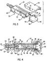
- Figures 3 and 4 are respective exploded isometric and top views of the sonic vibration transmitter;
- Figures 5A and 5B show respectively the forms of the electrical excitation of the transmitter and the sonic signals that arrive at the receiver;
- Figures 6A and 6B illustrate the encoded signals that operate the transmitter; and
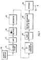
- Figure 7 is a block diagram schematic showing the circuit components that are used to decode the sonic signals at the receiver.
- As shown in Figure 1, an environment where the present invention has application, among others, is in a well bore 10 where a
drill string 9 including lengths ofdrill pipe 11 anddrill collars 12 is suspended. Adrill bit 13 at the lower end of thecollar string 12 is turned by the output shaft of the power section of amud motor assembly 14 which is powered by circulation of drilling mud down through thestring 9 and back to the surface via theannulus 15. In a directionally drilled borehole, abent housing 16 which forms a lower part of themotor assembly 14 establishes a small bend angle ϑ in the string below the power section of the motor. This angle causes theborehole 10 to be drilling along a curved path in the plane of the bend to gradually establish a new or different inclination. When a bend angle is being used, and rotation of thedrill string 9 is superimposed over the rotation of the motor drive shaft, theborehole 10 will be drilled straight ahead as thebend point 6 merely orbits about the longitudinal axis of the borehole. To drill straight ahead without rotation, thebent housing 16 can be adjusted either at surface, or downhole to eliminate the bend angle, the latter being accomplished with the downhole adjustable bent housing disclosed and claimed in U.S. Patent Application S.N. 649,107, filed February 1, 1991, incorporated herein by reference. In the alternative, thedrill string 9 can be temporarily removed to adjust thebent housing 16 by removing the bend, or replacing it with a motor having a straight housing. Of course, a bent sub (not shown) well known to those skilled in the art can be located in the drill string above themotor assembly 14 to provide the bend angle. - The
drill collar portion 12 of thedrill string 9 includes asensor sub 20 that preferably is located between the upper andlower bearing assemblies motor assembly 14 so as to be as near to thebit 13 as is practically possible. At this location, measurements of certain borehole parameters, such as inclination and tool face, and certain geological properties of the formation such as resistivity and natural radioactivity, are made near thebit 13 and transmitted to the surface in real time. Other measurements related to motor and bit performance also can be made. Again, a full description ofsensor sub 20 can be found in commonly-assigned U.S. Pat. App. S.N. filed concurrently herewith and incorporated earlier herein by reference. - A
transmitter 32, which is housed in an enclosed cavity between inner and outer tubular members that form thesensor sub 20 and provide an atmospheric pressure environment for the transmitter and other measurement systems, functions to create sonic vibrations that are representative of the measurements made bysensor sub 20 and to couple the vibrations to the walls of the metal members. The vibrations travel upward at the speed of sound in such metal to areceiver sub 34 that is associated with anMWD tool 19 by being connected thereto or by being an integral part thereof. TheMWD tool 19 is of a well known type that transmits information to the surface in the form of pressure pulses in the mud stream, and is located in thedrill string 9 above thedrilling motor 14. Examples of MWD tools that can be used are shown in U.S. Patent Nos. 4,100,528, 4,103,281, 4,167,000 and 3,309,656, which are incorporated herein by reference. A typical location for theMWD tool 19 is at the upper end of anonmagnetic drill collar 8 which is attached to the upper end of themotor assembly 14. TheMWD tool 19 makes measurements similar to those mentioned above, and others; however, its measurements are sometimes being made up to 150-200 feet above the bottom of theborehole 10. Other elements such as a stabilizer 7 also can be included in thedrill string 9. - In accordance with the present invention, sonic vibrations produced by the
transmitter 32 are encoded or modulated according to measurements made just above thebit 13 bysensor sub 20. These vibrations travel through the walls of the various components ofdrill string 9 thereabove. As shown in Figure 2, electrical signals representing the various measurements S₁, S₂,...SN are fed from anencoder 24 and atiming circuit 25 which function together to provide excitation signals to thetransmitter 32 which are digitally encoded in a manner that will be discussed in further detail below. Thetransmitter 32 includes a transducer in the form of a stack of ceramic crystals elements which generate the sonic vibrations when excited by electrical voltages. The vibrations travel upward through metal walls of themud motor assembly 14 and thedrill collar 15 located above it to thereceiver sub 34 that houses a receivingtransducer 35 firmly mounted in contact with the inner wall surface ofreceiver sub 34. The receivingtransducer 35 may be constructed substantially the same astransmitter 32, but preferably is a commercial piezoelectric accelerometer such as an Endevco Model 2221F. Receivingtransducer 35 responds to these vibrations and provides output signals which are preamplified 365, filtered atfilter 27, amplified atamplifier 28, and decoded at 29. The decoded signals fromdecoder 29 are applied to a microprocessor in theMWD tool 19 which includes a valve that operates to relay signals to the surface in the form of pressure pulses in the mud stream. - In another embodiment of the present invention,
receiver sub 34 is employed as a repeater station, the output signals of which being fed to another transmittingtransducer 32 that sends corresponding sonic vibrations further uphole through the metal members of thedrill string 9. The process of receiving and sending by way of a repeater can be carried out at various levels in the drill string until sonic vibration signals arrive at the surface where they are detected, decoded and displayed. The sonic transducer assemblies of the present invention which now will be described in further detail. - As shown in detail in Figures 3 and 4, the sonic transmitter assembly indicated generally at 32 includes a generally
rectangular body 70 that has a longitudinal recess 71 in which is mounted a number of ceramic crystals generally indicated as 72 which are stacked side by side. The outer end of the recess 71 slidably receives theboss 36 on the rear of acoupling block 37 in a manner such that the rear wall ofcoupling block 37 engages the front end of the stack ofcrystal elements 35. Theblock 37 has opposite side wall surfaces 38, anouter end surface 40 andtop surface 41 which can be inclined as shown. Guide lugs 42 extend outward on thesides 38 of theblock 37 and are longitudinally aligned with front and rear guide lugs 43 and 43' on opposite sides of thebody 70. As shown in Figure 4, threadedholes 45 are formed in theblock 37 on opposite sides of theboss 36, and the holes receive theend portions 46 of a pair of threadedrods 47 which extend through longitudinal bores in thebody 70 and pass out through the rear thereof so that nuts 48 can be used to tighten the rear face of theboss 36 against the front of the stack ofcrystals 72. Another threaded bore 50 is formed in the center of the rear portion 51 of thebody 70 and receives anelongated stud 52 having a plurality of relativelystiff springs 53, for example bellville washers, mounted thereon. Thehead 54 of thestud 52 extends with longitudinal play into arecess 55 in thesensor sub 20, so that thesprings 53 can react between a washer 53' which rests against therear wall 56 of thebody 70 and anopposed wall surface 57 on thesub 20. Thesprings 53 force thebody 70 upward in a manner such that thefront surface 40 of thecoupling block 37 remains firmly engaged against atransverse wall 58 at the upper end of the cavity in which theassembly 32 is mounted. This construction not only provides optimum sonic coupling, but also allows for slight longitudinal dimensional changes that may occur on account of high downhole temperatures. A coverplate 60 (Figure 3) can be provided which is attached byscrews 61 to the body 33. - As shown in Figure 4, the
ceramic crystals 72 are separated by thinconductive sheets 62 so that voltages can be applied to each crystal. The crystals are alternately oriented respecting their direction of polarization, and alternating ones of thesheets 62 are connected to the negative orground lead 63, with the balance of the sheets being connected to a positive lead 63'. Voltages applied across theleads 63, 63' produce minute strains in eachcrystal element 72 that cumulatively effect longitudinal displacements of thefront end 64 of the stack. These displacements create sonic vibrations which are coupled by theblock 37 into the metal wall of the housing of thesensor sub 20, from where they travel upward through the various tubular metal members that are connected thereabove toreceiver sub 34. - As shown in Figure 5A, the voltages which are applied across the
leads 63, 63' as a result of operation of theencoder 24 andtiming circuit 25 preferably produce a form ofexcitation 66 having four cycles, which is a number that has been found to be optimum in the sense that maximum sonic signal amplitude is produced for a certain amount of electrical energy. This package of cycles, called herein a "burst", generates a corresponding burst of compression waves 67 andshear waves 68 in the housing of thesensor sub 20 as shown in Figure 5B. Transverse bending waves (not shown) also may be produced. The excitation signals 66 can be encoded in various ways, but preferably digitally in terms of the repetition rates of the bursts. For example, a bit "1" can correspond to one repetition rate, and a "0" bit to another rate. As an example, 6.2 milliseconds between bursts can be the repetition rate for a bit 1 as shown in Figure 6A, and 12.4 milliseconds between bursts for abit 0 as shown in Figure 6B. - After a short time delay due to travel time up through the walls of the steel pipe members, the sonic vibrations arrive at the
receiver sub 34 which houses a receivingtransducer 35. Thetransducer 35 can be essentially identical to thetransmitter transducer 32 described above and therefore need not be again described in detail, except to note that as a receiver, sonic vibrations applied to it result in an electric signal. In operation, the sonic vibrations coming up thedrill collar 8 and into the housing of thereceiver sub 34 are coupled into thecoupling block 37 of thereceiver transducer 35 which produce electrical output signals. In a preferred embodiment of the present invention, a conventional accelerometer is included inreceiver sub 34 as the means for detecting the modulated sonic signals produced bytransmitter 32 insensor sub 20. The accelerometer, such as an Endevco Model 2221F, is firmly mounted against the outer wall ofreceiver sub 34 with its sensitive axis perpendicular thereto. The accelerometer is sensitive to sonic vibrations having the same frequency range as those transmitted bytransmitter 32, which preferably is around 25 KHz. In either case, the output signals from receivingtransducer 35 are processed and decoded as shown in Figure 7. - The output signals from receiving
transducer 35 inreceiver sub 34 are fed to afilter 75 that blocks low frequency noise signals that are typically generated during the drilling process. When the "transmitter 35" type of receiver is used,filter 75 is preferably passive and the output signal is diode clamped to avoid very large and potentially damaging voltages that can be generating by the piezoelectric crystal stack when subjected to the high shocks encountered while drilling. Otherwise, when an accelerometer is used for receivingtransducer 34, a pre-amplifier is used ahead ofhigh pass filter 75, which can be an active filter, since the signal generated by such an accelerometer is typically small. In either case, the resultant signal is then amplified atamplifier 77, rectified byrectifier 76, and integrated byintegrator 80. From there, the signal is fed to acomparator 81 being supplied with a constant reference voltage for comparison, which produces a signal when the signal fromintegrator 80 is above a predetermined threshold. The signals fromcomparator 81 are received byshift register 82 at one of two rates -- either 6.25 msec between bursts representing a logic bit "1", or 12.5 msec between bursts representing a logic bit "0". Theshift register 82 looks for a pattern in 12.5 msec windows and makes an inquiry attimes 0 msec, 5.25 msec, 6.25 msec, and 11.5 msec. This results in 1010 being shifted intoshift register 82 for a logic "1" and 1000 for a logic "0". For redundancy, this pattern is preferably repeated four times resulting in a 100 msec/bit data rate, or 10 bits/sec. These bit patterns are shifted to thepattern recognition 83 where a 5 volt signal for 1010 ("1") or a 0 volt signal for 1000 ("0") is generated and transferred to interface 84. All other patterns (e.g. 1111, 1011, and 1101 are considered generated by noise and therefore ignored, and the level remains that which was previously set until a valid pattern is recognized. The signal frominterface 84 is thus the decoded signal from thesensor sub 20 that is fed to the microprocessor associated with theMWD tool 19. - As noted above, in the event sonic vibration signals are to be sent further uphole rather than to the
MWD tool 19, the filtered and amplified signals from thereceiver transducer 35 are used to drive a transmitting transducer like that shown in Figures 3 and 4 which is mounted adjacent thereto and which has its own power supply (not shown). In this manner the receiving and transmitting pairs of transducers can be mounted in short length subs that are fixed at various stations or levels in a drill string to transmit intelligible information to the surface. - Where the present invention is used in connection with directional drilling, the combination of tool string components shown in Figure 1, which is an example of a commonly-used steerable system with the exception of
sensor sub 20, is assembled and lowered into the borehole 10 on thedrill string 9. When the mud pumps at the surface are started to initiate circulation, the power section of thedrilling motor assembly 14 rotates the drive shaft that extends down through thebent housing 16 and thesensor sub 22 to where it is connected to a spindle that is attached to thebit 13. If thebent housing 16 is operated to establish a bend angle, and thedrill string 9 is not rotated, the trajectory of thebit 13 will be along a curved path. Otherwise the hole can be drilled straight ahead in response to rotation of thedrill string 9 which is superimposed over rotation of the output shaft of the drilling motor. The various measurements mentioned above can be made continuously or intermittently withsensor sub 20 as the hole is deepened, namely inclination and azimuth measurements, and resistivity and gamma ray measurements. Other measurements that are of interest in connection with a well drilling process also can be made, for example drive shaft rpm and tool vibration. - The signals that represent the levels of each of the various measurements are inputted to an
encoder 24 which, together with thetiming circuit 25, provide an encoded sequence or train of electrical excitations in the form of voltage bursts that are applied across theleads 63, 63' of thesonic transmitter 32. Such sequence can include a plurality of discrete time frames so that a certain frame represents a particular measurement, plus a starting or timing frame. Thecrystals 72 oftransmitter 32 undergo longitudinal displacements which drive thecoupling block 37 in a manner such that it generates corresponding sonic waves or vibrations in the housing of thesensor sub 20. The vibrations travel upward primarily in the walls of thebent housing 16, the housing of themud motor 14, the walls of the drill collar 18, and other metal components which cumulatively form a transmission path to the receivingtransducer 35 within thereceiver sub 34. The vibrations excite thetransducer 35 which produces an output signal representative of the transmitted signals. These signals are filtered, amplified and decoded by the circuits shown in Figures 2 and 7, with the resulting output being fed to a receive line of a microprocessor in theMWD tool 19. The internal controls of theMWD tool 19 cause it to produce modulated pressure pulses in the mud stream that are, in part, representative of each of the measurements made at thesensor sub 20. These pulses are detected at the surface, decoded, and processed so that the various values of the downhole measurements are available for analysis substantially in real time. - It has been found that the steel walls of the
drill string components drill bit 13 is turning on bottom, the various sources of background noise that are produced limit the transmission distance. However, the frequencies used in the operation of the present invention are well above the frequency range of most all of the noise that is generated while drilling, so that there is a good separation between the frequencies of the telemetering signal and the drilling noise. Preferably, transmitter 30 is operated at the resonant frequency of the ceramic crystals in the transmitter 30, which is about 25 KHz, although operation can fall in the range of between 20 and 40 KHz. - It now will be recognized that a new and improved telemetry system has been disclosed which meets all the objectives and has all the features and advantages of the present invention. Since certain changes or modifications may be made in the disclosed embodiment without departing from the inventive concepts involved, it is the aim of the appended claims to cover all such changes and modifications falling within the true spirit and scope of the present invention.
Claims (22)
- A transducer assembly for generating sonic vibrations and adapted to couple said vibrations into a metal member of a drill string, comprising:
a body having a recess formed therein;
an elongated stack of ceramic crystal members mounted in said recess and having an outer end;
conductor means for applying electrical signals to said crystal members which induce strains therein that cumulatively effect longitudinal displacements of said outer end;
coupling block means having one wall surface engaging said outer end of said stack and another wall surface abutting a companion wall surface of said metal member for coupling said vibrations into said metal member; and
resilient means engaging said body for forcing said stack of ceramic members and said coupling block means against said companion wall surface to provide efficient coupling of said vibrations into said member. - The assembly of claim 1 wherein said resilient means reacts against an outer wall of said body and allows small dimensional changes to occur that are caused by high temperatures in a well bore while maintaining said coupling block means firmly against said companion wall surface.
- The assembly of claim 2 wherein said resilient means includes a plurality of frusto-conical spring washers; and means for mounting said washers in longitudinal alignment with said body.
- The assembly of claim 1 further including longitudinal guide means on said coupling block means and said body for providing precise alignment thereof with respect to said companion surface.
- The assembly of claim 1 further including adjustable means for tightening said coupling block means against said outer end of said stack of crystal members with a selected pressure.
- The assembly of claim 1 further including means for applying spaced bursts of electrical excitations to said crystal members, said applying means comprising encoder and timing circuit means for determining said encoding, each of said bursts having a selected plurality of cycles so that the repetitive rate of said bursts provides a means for encoding said sonic vibrations to represent measurements made in a well bore.
- The assembly of claim 6 wherein of each of said bursts includes a plurality of cycles of about 4 to provide optimum sonic energy output for a discrete amount of electrical energy input.
- The assembly of claim 6 wherein said encoding is digital in terms of the repetition rate of respective ones of said bursts, so that a bit 1 corresponds to one of said repetition rates, and a bit 0 corresponds to another of said repetition rates.
- The assembly of claim 6 wherein the frequency of said sonic vibrations is in the range of from 15 KHz to 40 KHz.
- The assembly of claim 6 wherein the frequency of said sonic vibrations is about 25 KHz to discriminate against lower background noise frequencies.
- A receiving transducer assembly for picking up sonic signals traveling through a metal member in a drill string and producing output signals that are representative thereof, comprising:
a body having a recess formed therein;
an elongated stack of ceramic crystal members mounted in said recess and having an outer end;
conductor means for transmitting electrical signals generated by said crystal members when strains are induced therein in response to sonic vibration;
coupling block means having one wall surface engaging said outer end of said stack and another wall surface abutting a companion wall surface on said metal member for coupling sonic vibrations in said metal member into said stack of crystal members; and
resilient means engaging said body for forcing said stack of crystal members and said coupling block means against said companion wall surface to provide efficient coupling of said sonic vibrations into said crystal members via said coupling block means. - The apparatus of claim 11 further including longitudinally spaced guides on said body and said coupling block means for providing precise longitudinal alignment of said body and said coupling block means with said companion surface.
- The apparatus of claim 11 further including adjustable means for tightening said coupling block means against said outer end of said stack of crystal members with a selected pressure.
- The apparatus of claim 11 wherein said resilient means is constituted by a plurality of frusto-conical spring washers; and further including means on said body and extending through said plurality of spring washers for mounting said washers in longitudinal alignment with said body.
- The apparatus of claim 11 wherein said crystal members are alternately oriented with respect to their directions of polarization, and further including:
a pair of conductor wires connected respectively to the opposite sides of each of said crystal members for providing output voltage signals that are indicative of strains applied to said crystal members by said sonic vibrations;
high pass filter means receiving said output signals from said crystal members and adapted to reject low energy noise signals contained therein;
means for amplifying the electrical signals that pass through said filter means;
means for recognizing a characteristic of said signals which represents intelligence, wherein said signals include time-spaced bursts of pluralities of cycles, and wherein said characteristic is the repetition rate of each of said bursts. - A telemetry system for use in transmitting sonic vibrations that represent measurements made in a borehole through a portion of a drill string having metal tubular members that are connected to one another, comprising:
means for producing a series of bursts of electrical excitations that are digitally encoded in accordance with said measurements to have one of two selected repetitive rates, each of said bursts having a predetermined number of oscillations;
means for applying said excitations to a first transducer means which includes a ceramic crystal assembly that produces sonic vibrations which correspond to said bursts;
means for coupling said vibrations into one of said metal members so that said vibrations travel through the walls thereof; and
second transducer means on another of said metal members for sensing said vibrations and producing electrical output signals which are representative thereof. - The system of claim 16 further including means associated with said second transducer means for detecting the repetition rate of said output signals.
- The system of claim 16 further including means for filtering said output signal to eliminate low energy signals, means for amplifying the output of said filtering means; and means for applying said amplified high energy signals as the excitation for another ceramic crystal assembly which produces sonic vibrations and couples them into another of said metal members for transmission further along said drill string.
- The system of claim 16 wherein said second transducer means includes a ceramic crystal assembly that senses sonic vibrations and produces electrical output signals that are representative thereof, said last-mentioned crystal assembly being so constructed and arranged that it resonates at the carrier frequency of said transmitted signals to provide a band-pass filter effect which improves the signal-to-noise ratio.
- The system of claim 16 wherein said second transducer means comprises meter means for sensing accelerations and providing output signals representative thereof.
- A method of transmitting borehole measurements along a portion of a drill string that includes metal tubular members which are connected to one another, comprising the steps of:
producing a series of bursts of electrical excitations that are encoded in accordance with said measurements, each of said bursts having a predetermined number of oscillations and wherein the manner in which said bursts are encoded includes modulating a carrier frequency by controlling the repetition rate of said bursts of electrical excitations in a manner such that one repetition rate thereof corresponds to a 1 bit and another repetition rate corresponds to a 0 bit;
applying said excitations to a first transducer means which includes a ceramic crystal assembly that produces sonic vibrations corresponding to said bursts;
coupling said vibrations into one of said metal members so that said vibrations travel through the walls of said members;
sensing said vibrations with a second transducer means on another of said metal members and producing electrical output signals which are representative thereof; and
detecting the repetition rate of the output signals from said second transducer means. - The method of claim 21 including the additional steps of:
filtering the output signals from said second transducer means to eliminate low energy background noise signals;
amplifying said filtered signals; and
applying said amplified signals to a third transducer means which produces sonic vibrations and couples them into another of said metal members for transmission further along the drill string.
Applications Claiming Priority (2)
| Application Number | Priority Date | Filing Date | Title |
|---|---|---|---|
| US82323992A | 1992-01-21 | 1992-01-21 | |
| US823239 | 1992-01-21 |
Publications (2)
| Publication Number | Publication Date |
|---|---|
| EP0552833A1 true EP0552833A1 (en) | 1993-07-28 |
| EP0552833B1 EP0552833B1 (en) | 1996-11-06 |
Family
ID=25238184
Family Applications (1)
| Application Number | Title | Priority Date | Filing Date |
|---|---|---|---|
| EP93200100A Expired - Lifetime EP0552833B1 (en) | 1992-01-21 | 1993-01-15 | Sonic vibration telemetering system |
Country Status (4)
| Country | Link |
|---|---|
| US (1) | US5373481A (en) |
| EP (1) | EP0552833B1 (en) |
| DE (1) | DE69305754D1 (en) |
| NO (1) | NO306222B1 (en) |
Cited By (16)
| Publication number | Priority date | Publication date | Assignee | Title |
|---|---|---|---|---|
| US5568448A (en) * | 1991-04-25 | 1996-10-22 | Mitsubishi Denki Kabushiki Kaisha | System for transmitting a signal |
| US5675325A (en) * | 1995-10-20 | 1997-10-07 | Japan National Oil Corporation | Information transmitting apparatus using tube body |
| US5924499A (en) * | 1997-04-21 | 1999-07-20 | Halliburton Energy Services, Inc. | Acoustic data link and formation property sensor for downhole MWD system |
| EP0994237A2 (en) | 1998-10-14 | 2000-04-19 | Japan National Oil Corporation | Acoustic wave transmission system and method for transmitting an acoustic wave to a drilling metal tubular member |
| EP1082828A1 (en) * | 1998-05-29 | 2001-03-14 | Halliburton Energy Services, Inc. | Single point contact acoustic transmitter |
| US6213250B1 (en) | 1998-09-25 | 2001-04-10 | Dresser Industries, Inc. | Transducer for acoustic logging |
| US6366531B1 (en) | 1998-09-22 | 2002-04-02 | Dresser Industries, Inc. | Method and apparatus for acoustic logging |
| CN1088142C (en) * | 1994-12-05 | 2002-07-24 | 青岛海洋大学 | Acoustic detector for oil well radio transmitted pressure and temp. parameters |
| GB2373804A (en) * | 1998-01-28 | 2002-10-02 | Baker Hughes Inc | Vibration detection method for downhole tool |
| US6564899B1 (en) | 1998-09-24 | 2003-05-20 | Dresser Industries, Inc. | Method and apparatus for absorbing acoustic energy |
| US6624759B2 (en) | 1998-01-28 | 2003-09-23 | Baker Hughes Incorporated | Remote actuation of downhole tools using vibration |
| US6693554B2 (en) | 1999-02-19 | 2004-02-17 | Halliburton Energy Services, Inc. | Casing mounted sensors, actuators and generators |
| US7339494B2 (en) | 2004-07-01 | 2008-03-04 | Halliburton Energy Services, Inc. | Acoustic telemetry transceiver |
| US7997380B2 (en) | 2004-06-22 | 2011-08-16 | Halliburton Energy Services, Inc. | Low frequency acoustic attenuator |
| EP2543813A1 (en) * | 2011-07-08 | 2013-01-09 | Nederlandse Organisatie voor toegepast -natuurwetenschappelijk onderzoek TNO | A telemetry system, a pipe and a method of transmitting information |
| US11649717B2 (en) | 2018-09-17 | 2023-05-16 | Saudi Arabian Oil Company | Systems and methods for sensing downhole cement sheath parameters |
Families Citing this family (48)
| Publication number | Priority date | Publication date | Assignee | Title |
|---|---|---|---|---|
| US5667023B1 (en) * | 1994-11-22 | 2000-04-18 | Baker Hughes Inc | Method and apparatus for drilling and completing wells |
| GB2311427B (en) * | 1996-03-22 | 2000-02-09 | Marconi Gec Ltd | A drill string sub assembly |
| US6434084B1 (en) | 1999-11-22 | 2002-08-13 | Halliburton Energy Services, Inc. | Adaptive acoustic channel equalizer & tuning method |
| US6618674B2 (en) | 2001-07-31 | 2003-09-09 | Schlumberger Technology Corporation | Method and apparatus for measurement alignment |
| US6933856B2 (en) * | 2001-08-02 | 2005-08-23 | Halliburton Energy Services, Inc. | Adaptive acoustic transmitter controller apparatus and method |
| US7477162B2 (en) * | 2005-10-11 | 2009-01-13 | Schlumberger Technology Corporation | Wireless electromagnetic telemetry system and method for bottomhole assembly |
| US7595737B2 (en) * | 2006-07-24 | 2009-09-29 | Halliburton Energy Services, Inc. | Shear coupled acoustic telemetry system |
| US7557492B2 (en) | 2006-07-24 | 2009-07-07 | Halliburton Energy Services, Inc. | Thermal expansion matching for acoustic telemetry system |
| US7864629B2 (en) * | 2007-11-20 | 2011-01-04 | Precision Energy Services, Inc. | Monopole acoustic transmitter comprising a plurality of piezoelectric discs |
| US20100133004A1 (en) * | 2008-12-03 | 2010-06-03 | Halliburton Energy Services, Inc. | System and Method for Verifying Perforating Gun Status Prior to Perforating a Wellbore |
| CN101783714B (en) * | 2009-01-21 | 2013-05-15 | 北京理工大学 | Method and device for acquiring transmission data |
| US8881414B2 (en) | 2009-08-17 | 2014-11-11 | Magnum Drilling Services, Inc. | Inclination measurement devices and methods of use |
| US8528219B2 (en) | 2009-08-17 | 2013-09-10 | Magnum Drilling Services, Inc. | Inclination measurement devices and methods of use |
| US20130298652A1 (en) * | 2012-05-08 | 2013-11-14 | Logimesh IP, LLC | Systems and methods for asset monitoring |
| WO2014043073A2 (en) * | 2012-09-14 | 2014-03-20 | Scientific Drilling International, Inc. | Early detection and anti-collision system |
| WO2014100272A1 (en) * | 2012-12-19 | 2014-06-26 | Exxonmobil Upstream Research Company | Apparatus and method for monitoring fluid flow in a wellbore using acoustic signals |
| US20150292319A1 (en) * | 2012-12-19 | 2015-10-15 | Exxon-Mobil Upstream Research Company | Telemetry for Wireless Electro-Acoustical Transmission of Data Along a Wellbore |
| US9644440B2 (en) | 2013-10-21 | 2017-05-09 | Laguna Oil Tools, Llc | Systems and methods for producing forced axial vibration of a drillstring |
| US10295500B2 (en) | 2014-03-27 | 2019-05-21 | Ultrapower Inc. | Electro-acoustic sensors for remote monitoring |
| US9574439B2 (en) * | 2014-06-04 | 2017-02-21 | Baker Hughes Incorporated | Downhole vibratory communication system and method |
| US10508536B2 (en) | 2014-09-12 | 2019-12-17 | Exxonmobil Upstream Research Company | Discrete wellbore devices, hydrocarbon wells including a downhole communication network and the discrete wellbore devices and systems and methods including the same |
| US10408047B2 (en) | 2015-01-26 | 2019-09-10 | Exxonmobil Upstream Research Company | Real-time well surveillance using a wireless network and an in-wellbore tool |
| CN106014394B (en) * | 2016-06-30 | 2023-04-07 | 中国石油天然气集团有限公司 | Device for transmitting while-drilling bottom hole pressure data by sound waves and using method thereof |
| US10415376B2 (en) | 2016-08-30 | 2019-09-17 | Exxonmobil Upstream Research Company | Dual transducer communications node for downhole acoustic wireless networks and method employing same |
| US10487647B2 (en) | 2016-08-30 | 2019-11-26 | Exxonmobil Upstream Research Company | Hybrid downhole acoustic wireless network |
| US10344583B2 (en) | 2016-08-30 | 2019-07-09 | Exxonmobil Upstream Research Company | Acoustic housing for tubulars |
| US10526888B2 (en) | 2016-08-30 | 2020-01-07 | Exxonmobil Upstream Research Company | Downhole multiphase flow sensing methods |
| US10590759B2 (en) | 2016-08-30 | 2020-03-17 | Exxonmobil Upstream Research Company | Zonal isolation devices including sensing and wireless telemetry and methods of utilizing the same |
| US10697287B2 (en) | 2016-08-30 | 2020-06-30 | Exxonmobil Upstream Research Company | Plunger lift monitoring via a downhole wireless network field |
| US10465505B2 (en) | 2016-08-30 | 2019-11-05 | Exxonmobil Upstream Research Company | Reservoir formation characterization using a downhole wireless network |
| US10364669B2 (en) | 2016-08-30 | 2019-07-30 | Exxonmobil Upstream Research Company | Methods of acoustically communicating and wells that utilize the methods |
| US10724363B2 (en) | 2017-10-13 | 2020-07-28 | Exxonmobil Upstream Research Company | Method and system for performing hydrocarbon operations with mixed communication networks |
| US10837276B2 (en) | 2017-10-13 | 2020-11-17 | Exxonmobil Upstream Research Company | Method and system for performing wireless ultrasonic communications along a drilling string |
| WO2019074657A1 (en) | 2017-10-13 | 2019-04-18 | Exxonmobil Upstream Research Company | Method and system for performing operations using communications |
| CN111201454B (en) | 2017-10-13 | 2022-09-09 | 埃克森美孚上游研究公司 | Method and system for performing operations with communications |
| US10697288B2 (en) | 2017-10-13 | 2020-06-30 | Exxonmobil Upstream Research Company | Dual transducer communications node including piezo pre-tensioning for acoustic wireless networks and method employing same |
| AU2018347465B2 (en) | 2017-10-13 | 2021-10-07 | Exxonmobil Upstream Research Company | Method and system for performing communications using aliasing |
| US10690794B2 (en) | 2017-11-17 | 2020-06-23 | Exxonmobil Upstream Research Company | Method and system for performing operations using communications for a hydrocarbon system |
| WO2019099188A1 (en) | 2017-11-17 | 2019-05-23 | Exxonmobil Upstream Research Company | Method and system for performing wireless ultrasonic communications along tubular members |
| US10844708B2 (en) | 2017-12-20 | 2020-11-24 | Exxonmobil Upstream Research Company | Energy efficient method of retrieving wireless networked sensor data |
| US11313215B2 (en) | 2017-12-29 | 2022-04-26 | Exxonmobil Upstream Research Company | Methods and systems for monitoring and optimizing reservoir stimulation operations |
| US11156081B2 (en) | 2017-12-29 | 2021-10-26 | Exxonmobil Upstream Research Company | Methods and systems for operating and maintaining a downhole wireless network |
| CA3090799C (en) | 2018-02-08 | 2023-10-10 | Exxonmobil Upstream Research Company | Methods of network peer identification and self-organization using unique tonal signatures and wells that use the methods |
| US11268378B2 (en) | 2018-02-09 | 2022-03-08 | Exxonmobil Upstream Research Company | Downhole wireless communication node and sensor/tools interface |
| US11293280B2 (en) | 2018-12-19 | 2022-04-05 | Exxonmobil Upstream Research Company | Method and system for monitoring post-stimulation operations through acoustic wireless sensor network |
| US11952886B2 (en) | 2018-12-19 | 2024-04-09 | ExxonMobil Technology and Engineering Company | Method and system for monitoring sand production through acoustic wireless sensor network |
| CN111503216B (en) * | 2020-03-30 | 2021-03-30 | 中国科学院地质与地球物理研究所 | Self-adjusting damping shock absorber for drilling instrument and adjusting method thereof |
| US20220106875A1 (en) * | 2020-10-06 | 2022-04-07 | Gordon Technologies Llc | Acoustic datalink useful in downhole applications |
Citations (4)
| Publication number | Priority date | Publication date | Assignee | Title |
|---|---|---|---|---|
| US4231112A (en) * | 1970-07-30 | 1980-10-28 | Fred M. Dellorfano, Jr. | High-power underwater transducer with improved performance and reliability characteristics and method for controlling said improved characteristics |
| US4282588A (en) * | 1980-01-21 | 1981-08-04 | Sperry Corporation | Resonant acoustic transducer and driver system for a well drilling string communication system |
| DE3309068C2 (en) * | 1983-03-14 | 1987-04-23 | Mtu Muenchen Gmbh | |
| US4782910A (en) * | 1986-05-23 | 1988-11-08 | Mobil Oil Corporation | Bi-polar bender transducer for logging tools |
Family Cites Families (28)
| Publication number | Priority date | Publication date | Assignee | Title |
|---|---|---|---|---|
| US2910133A (en) * | 1952-12-11 | 1959-10-27 | Roland B Hudson | Method of continuous well logging during drilling |
| US2957159A (en) * | 1955-02-07 | 1960-10-18 | Phillips Petroleum Co | Measuring device |
| US3252225A (en) * | 1962-09-04 | 1966-05-24 | Ed Wight | Signal generator indicating vertical deviation |
| US3233674A (en) * | 1963-07-22 | 1966-02-08 | Baker Oil Tools Inc | Subsurface well apparatus |
| US3697940A (en) * | 1968-08-23 | 1972-10-10 | Bohdan Jiri Berka | Signalling system for bore logging |
| US3588804A (en) * | 1969-06-16 | 1971-06-28 | Globe Universal Sciences | Telemetering system for use in boreholes |
| US3900827A (en) * | 1971-02-08 | 1975-08-19 | American Petroscience Corp | Telemetering system for oil wells using reaction modulator |
| US4038632A (en) * | 1972-10-02 | 1977-07-26 | Del Norte Technology, Inc. | Oil and gas well disaster valve control system |
| US3961308A (en) * | 1972-10-02 | 1976-06-01 | Del Norte Technology, Inc. | Oil and gas well disaster valve control system |
| US3930220A (en) * | 1973-09-12 | 1975-12-30 | Sun Oil Co Pennsylvania | Borehole signalling by acoustic energy |
| US4066995A (en) * | 1975-01-12 | 1978-01-03 | Sperry Rand Corporation | Acoustic isolation for a telemetry system on a drill string |
| US4293936A (en) * | 1976-12-30 | 1981-10-06 | Sperry-Sun, Inc. | Telemetry system |
| US4139836A (en) * | 1977-07-01 | 1979-02-13 | Sperry-Sun, Inc. | Wellbore instrument hanger |
| US4390975A (en) * | 1978-03-20 | 1983-06-28 | Nl Sperry-Sun, Inc. | Data transmission in a drill string |
| US4283779A (en) * | 1979-03-19 | 1981-08-11 | American Petroscience Corporation | Torsional wave generator |
| US4283780A (en) * | 1980-01-21 | 1981-08-11 | Sperry Corporation | Resonant acoustic transducer system for a well drilling string |
| US4302826A (en) * | 1980-01-21 | 1981-11-24 | Sperry Corporation | Resonant acoustic transducer system for a well drilling string |
| US4314365A (en) * | 1980-01-21 | 1982-02-02 | Exxon Production Research Company | Acoustic transmitter and method to produce essentially longitudinal, acoustic waves |
| US4562559A (en) * | 1981-01-19 | 1985-12-31 | Nl Sperry Sun, Inc. | Borehole acoustic telemetry system with phase shifted signal |
| US4518888A (en) * | 1982-12-27 | 1985-05-21 | Nl Industries, Inc. | Downhole apparatus for absorbing vibratory energy to generate electrical power |
| US4597067A (en) * | 1984-04-18 | 1986-06-24 | Conoco Inc. | Borehole monitoring device and method |
| DE3428931C1 (en) * | 1984-08-06 | 1985-06-05 | Norton Christensen, Inc., Salt Lake City, Utah | Device for the remote transmission of information from a borehole to the surface of the earth during the operation of a drilling rig |
| EP0408667B1 (en) * | 1988-04-21 | 1994-01-19 | Sandia Corporation | Acoustic data transmission through a drill string |
| US4992997A (en) * | 1988-04-29 | 1991-02-12 | Atlantic Richfield Company | Stress wave telemetry system for drillstems and tubing strings |
| WO1992001955A1 (en) * | 1990-07-16 | 1992-02-06 | Atlantic Richfield Company | Torsional force transducer and method of operation |
| US5128902A (en) * | 1990-10-29 | 1992-07-07 | Teleco Oilfield Services Inc. | Electromechanical transducer for acoustic telemetry system |
| US5050132A (en) * | 1990-11-07 | 1991-09-17 | Teleco Oilfield Services Inc. | Acoustic data transmission method |
| US5056067A (en) * | 1990-11-27 | 1991-10-08 | Teleco Oilfield Services Inc. | Analog circuit for controlling acoustic transducer arrays |
-
1993
- 1993-01-15 NO NO930146A patent/NO306222B1/en not_active IP Right Cessation
- 1993-01-15 EP EP93200100A patent/EP0552833B1/en not_active Expired - Lifetime
- 1993-01-15 DE DE69305754T patent/DE69305754D1/en not_active Expired - Lifetime
- 1993-07-06 US US08/086,567 patent/US5373481A/en not_active Expired - Lifetime
Patent Citations (4)
| Publication number | Priority date | Publication date | Assignee | Title |
|---|---|---|---|---|
| US4231112A (en) * | 1970-07-30 | 1980-10-28 | Fred M. Dellorfano, Jr. | High-power underwater transducer with improved performance and reliability characteristics and method for controlling said improved characteristics |
| US4282588A (en) * | 1980-01-21 | 1981-08-04 | Sperry Corporation | Resonant acoustic transducer and driver system for a well drilling string communication system |
| DE3309068C2 (en) * | 1983-03-14 | 1987-04-23 | Mtu Muenchen Gmbh | |
| US4782910A (en) * | 1986-05-23 | 1988-11-08 | Mobil Oil Corporation | Bi-polar bender transducer for logging tools |
Cited By (28)
| Publication number | Priority date | Publication date | Assignee | Title |
|---|---|---|---|---|
| US5568448A (en) * | 1991-04-25 | 1996-10-22 | Mitsubishi Denki Kabushiki Kaisha | System for transmitting a signal |
| CN1088142C (en) * | 1994-12-05 | 2002-07-24 | 青岛海洋大学 | Acoustic detector for oil well radio transmitted pressure and temp. parameters |
| US5675325A (en) * | 1995-10-20 | 1997-10-07 | Japan National Oil Corporation | Information transmitting apparatus using tube body |
| US5924499A (en) * | 1997-04-21 | 1999-07-20 | Halliburton Energy Services, Inc. | Acoustic data link and formation property sensor for downhole MWD system |
| US6624759B2 (en) | 1998-01-28 | 2003-09-23 | Baker Hughes Incorporated | Remote actuation of downhole tools using vibration |
| GB2373804A (en) * | 1998-01-28 | 2002-10-02 | Baker Hughes Inc | Vibration detection method for downhole tool |
| GB2373804B (en) * | 1998-01-28 | 2002-12-18 | Baker Hughes Inc | Vibration detection method for downhole tool |
| EP1082828A1 (en) * | 1998-05-29 | 2001-03-14 | Halliburton Energy Services, Inc. | Single point contact acoustic transmitter |
| EP2260948A3 (en) * | 1998-05-29 | 2017-03-29 | Halliburton Energy Services, Inc. | Single point contact acoustic transmitter |
| EP1082828A4 (en) * | 1998-05-29 | 2006-03-15 | Halliburton Energy Serv Inc | Single point contact acoustic transmitter |
| EP2260949A3 (en) * | 1998-05-29 | 2017-04-12 | Halliburton Energy Services, Inc. | Single point contact acoustic transmitter |
| US6366531B1 (en) | 1998-09-22 | 2002-04-02 | Dresser Industries, Inc. | Method and apparatus for acoustic logging |
| US6564899B1 (en) | 1998-09-24 | 2003-05-20 | Dresser Industries, Inc. | Method and apparatus for absorbing acoustic energy |
| US6213250B1 (en) | 1998-09-25 | 2001-04-10 | Dresser Industries, Inc. | Transducer for acoustic logging |
| EP0994237A2 (en) | 1998-10-14 | 2000-04-19 | Japan National Oil Corporation | Acoustic wave transmission system and method for transmitting an acoustic wave to a drilling metal tubular member |
| US6987463B2 (en) | 1999-02-19 | 2006-01-17 | Halliburton Energy Services, Inc. | Method for collecting geological data from a well bore using casing mounted sensors |
| US7046165B2 (en) | 1999-02-19 | 2006-05-16 | Halliburton Energy Services, Inc. | Method for collecting geological data ahead of a drill bit |
| US7173542B2 (en) | 1999-02-19 | 2007-02-06 | Halliburton Energy Services, Inc. | Data relay for casing mounted sensors, actuators and generators |
| US7932834B2 (en) | 1999-02-19 | 2011-04-26 | Halliburton Energy Services. Inc. | Data relay system for instrument and controller attached to a drill string |
| US6747570B2 (en) | 1999-02-19 | 2004-06-08 | Halliburton Energy Services, Inc. | Method for preventing fracturing of a formation proximal to a casing shoe of well bore during drilling operations |
| US6693554B2 (en) | 1999-02-19 | 2004-02-17 | Halliburton Energy Services, Inc. | Casing mounted sensors, actuators and generators |
| US7997380B2 (en) | 2004-06-22 | 2011-08-16 | Halliburton Energy Services, Inc. | Low frequency acoustic attenuator |
| US7339494B2 (en) | 2004-07-01 | 2008-03-04 | Halliburton Energy Services, Inc. | Acoustic telemetry transceiver |
| US7777645B2 (en) | 2004-07-01 | 2010-08-17 | Halliburton Energy Services, Inc. | Acoustic telemetry transceiver |
| US8040249B2 (en) | 2004-07-01 | 2011-10-18 | Halliburton Energy Services, Inc. | Acoustic telemetry transceiver |
| EP2543813A1 (en) * | 2011-07-08 | 2013-01-09 | Nederlandse Organisatie voor toegepast -natuurwetenschappelijk onderzoek TNO | A telemetry system, a pipe and a method of transmitting information |
| WO2013009173A1 (en) * | 2011-07-08 | 2013-01-17 | Nederlandse Organisatie Voor Toegepast-Natuurwetenschappelijk Onderzoek Tno | A telemetry system, a pipe and a method of transmitting information |
| US11649717B2 (en) | 2018-09-17 | 2023-05-16 | Saudi Arabian Oil Company | Systems and methods for sensing downhole cement sheath parameters |
Also Published As
| Publication number | Publication date |
|---|---|
| US5373481A (en) | 1994-12-13 |
| NO930146D0 (en) | 1993-01-15 |
| EP0552833B1 (en) | 1996-11-06 |
| NO930146L (en) | 1993-07-22 |
| NO306222B1 (en) | 1999-10-04 |
| DE69305754D1 (en) | 1996-12-12 |
Similar Documents
| Publication | Publication Date | Title |
|---|---|---|
| US5373481A (en) | Sonic vibration telemetering system | |
| US5448227A (en) | Method of and apparatus for making near-bit measurements while drilling | |
| US5924499A (en) | Acoustic data link and formation property sensor for downhole MWD system | |
| EP0778473B1 (en) | Transducer for sonic logging-while-drilling | |
| US5166908A (en) | Piezoelectric transducer for high speed data transmission and method of operation | |
| US6912177B2 (en) | Transmission of data in boreholes | |
| US5159226A (en) | Torsional force transducer and method of operation | |
| US7398837B2 (en) | Drill bit assembly with a logging device | |
| EP0160678B1 (en) | Improved drilling method and apparatus | |
| US20110067928A1 (en) | Bottom-hole assembly, and a method and system for transmitting data from a bottom-hole assembly | |
| US4899844A (en) | Acoustical well logging method and apparatus | |
| US20090073806A1 (en) | Method and Apparatus for Generating Acoustic Signals with a Single Mode of Propagation | |
| US10619455B2 (en) | Subassembly for a bottom hole assembly of a drill string with communications link | |
| US10293376B2 (en) | Bender bar transducer with at least three resonance modes | |
| CA2269766A1 (en) | Method and system for cement bond evaluation in high acoustic velocity formations | |
| US20220106875A1 (en) | Acoustic datalink useful in downhole applications | |
| GB1598340A (en) | Telemetry system | |
| US4899319A (en) | Method for determining induced fracture azimuth in formations surrounding a cased well | |
| US20230349287A1 (en) | Acoustic datalink with shock absorbing tool useful in downhole applications | |
| JPH08130511A (en) | Pipe body transmitter | |
| CN108463613A (en) | Position scrambling in Differential Pulse Position Modulation | |
| CA2009175C (en) | Method for determining induced fracture azimuth in formations surrounding a cased well | |
| WO2022265658A1 (en) | Air layer for improved performance of transducer at low frequencies | |
| EP0113943A1 (en) | Shear wave acoustic logging system |
Legal Events
| Date | Code | Title | Description |
|---|---|---|---|
| PUAI | Public reference made under article 153(3) epc to a published international application that has entered the european phase |
Free format text: ORIGINAL CODE: 0009012 |
|
| AK | Designated contracting states |
Kind code of ref document: A1 Designated state(s): DE DK FR GB IT NL |
|
| 17P | Request for examination filed |
Effective date: 19931221 |
|
| 17Q | First examination report despatched |
Effective date: 19950531 |
|
| GRAG | Despatch of communication of intention to grant |
Free format text: ORIGINAL CODE: EPIDOS AGRA |
|
| GRAH | Despatch of communication of intention to grant a patent |
Free format text: ORIGINAL CODE: EPIDOS IGRA |
|
| GRAH | Despatch of communication of intention to grant a patent |
Free format text: ORIGINAL CODE: EPIDOS IGRA |
|
| GRAA | (expected) grant |
Free format text: ORIGINAL CODE: 0009210 |
|
| AK | Designated contracting states |
Kind code of ref document: B1 Designated state(s): DE DK FR GB IT NL |
|
| PG25 | Lapsed in a contracting state [announced via postgrant information from national office to epo] |
Ref country code: NL Free format text: LAPSE BECAUSE OF FAILURE TO SUBMIT A TRANSLATION OF THE DESCRIPTION OR TO PAY THE FEE WITHIN THE PRESCRIBED TIME-LIMIT Effective date: 19961106 Ref country code: IT Free format text: LAPSE BECAUSE OF FAILURE TO SUBMIT A TRANSLATION OF THE DESCRIPTION OR TO PAY THE FEE WITHIN THE PRE;WARNING: LAPSES OF ITALIAN PATENTS WITH EFFECTIVE DATE BEFORE 2007 MAY HAVE OCCURRED AT ANY TIME BEFORE 2007. THE CORRECT EFFECTIVE DATE MAY BE DIFFERENT FROM THE ONE RECORDED.SCRIBED TIME-LIMIT Effective date: 19961106 Ref country code: FR Effective date: 19961106 Ref country code: DK Effective date: 19961106 |
|
| REF | Corresponds to: |
Ref document number: 69305754 Country of ref document: DE Date of ref document: 19961212 |
|
| PG25 | Lapsed in a contracting state [announced via postgrant information from national office to epo] |
Ref country code: DE Effective date: 19970207 |
|
| NLV1 | Nl: lapsed or annulled due to failure to fulfill the requirements of art. 29p and 29m of the patents act | ||
| EN | Fr: translation not filed | ||
| PLBE | No opposition filed within time limit |
Free format text: ORIGINAL CODE: 0009261 |
|
| STAA | Information on the status of an ep patent application or granted ep patent |
Free format text: STATUS: NO OPPOSITION FILED WITHIN TIME LIMIT |
|
| 26N | No opposition filed | ||
| REG | Reference to a national code |
Ref country code: GB Ref legal event code: IF02 |
|
| PGFP | Annual fee paid to national office [announced via postgrant information from national office to epo] |
Ref country code: GB Payment date: 20020130 Year of fee payment: 10 |
|
| PG25 | Lapsed in a contracting state [announced via postgrant information from national office to epo] |
Ref country code: GB Free format text: LAPSE BECAUSE OF NON-PAYMENT OF DUE FEES Effective date: 20030115 |
|
| GBPC | Gb: european patent ceased through non-payment of renewal fee |