EP0550228A1 - Swash plate type compressor with variable displacemnet mechanism - Google Patents
Swash plate type compressor with variable displacemnet mechanism Download PDFInfo
- Publication number
- EP0550228A1 EP0550228A1 EP92311608A EP92311608A EP0550228A1 EP 0550228 A1 EP0550228 A1 EP 0550228A1 EP 92311608 A EP92311608 A EP 92311608A EP 92311608 A EP92311608 A EP 92311608A EP 0550228 A1 EP0550228 A1 EP 0550228A1
- Authority
- EP
- European Patent Office
- Prior art keywords
- swash plate
- drive shaft
- plate
- rotor
- compressor
- Prior art date
- Legal status (The legal status is an assumption and is not a legal conclusion. Google has not performed a legal analysis and makes no representation as to the accuracy of the status listed.)
- Granted
Links
Images


Classifications
-
- F—MECHANICAL ENGINEERING; LIGHTING; HEATING; WEAPONS; BLASTING
- F04—POSITIVE - DISPLACEMENT MACHINES FOR LIQUIDS; PUMPS FOR LIQUIDS OR ELASTIC FLUIDS
- F04B—POSITIVE-DISPLACEMENT MACHINES FOR LIQUIDS; PUMPS
- F04B25/00—Multi-stage pumps
- F04B25/04—Multi-stage pumps having cylinders coaxial with, or parallel or inclined to, main shaft axis
-
- F—MECHANICAL ENGINEERING; LIGHTING; HEATING; WEAPONS; BLASTING
- F04—POSITIVE - DISPLACEMENT MACHINES FOR LIQUIDS; PUMPS FOR LIQUIDS OR ELASTIC FLUIDS
- F04B—POSITIVE-DISPLACEMENT MACHINES FOR LIQUIDS; PUMPS
- F04B27/00—Multi-cylinder pumps specially adapted for elastic fluids and characterised by number or arrangement of cylinders
- F04B27/08—Multi-cylinder pumps specially adapted for elastic fluids and characterised by number or arrangement of cylinders having cylinders coaxial with, or parallel or inclined to, main shaft axis
- F04B27/10—Multi-cylinder pumps specially adapted for elastic fluids and characterised by number or arrangement of cylinders having cylinders coaxial with, or parallel or inclined to, main shaft axis having stationary cylinders
- F04B27/1036—Component parts, details, e.g. sealings, lubrication
- F04B27/1054—Actuating elements
- F04B27/1072—Pivot mechanisms
-
- F—MECHANICAL ENGINEERING; LIGHTING; HEATING; WEAPONS; BLASTING
- F01—MACHINES OR ENGINES IN GENERAL; ENGINE PLANTS IN GENERAL; STEAM ENGINES
- F01B—MACHINES OR ENGINES, IN GENERAL OR OF POSITIVE-DISPLACEMENT TYPE, e.g. STEAM ENGINES
- F01B3/00—Reciprocating-piston machines or engines with cylinder axes coaxial with, or parallel or inclined to, main shaft axis
- F01B3/10—Control of working-fluid admission or discharge peculiar thereto
- F01B3/103—Control of working-fluid admission or discharge peculiar thereto for machines with rotary cylinder block
- F01B3/106—Control of working-fluid admission or discharge peculiar thereto for machines with rotary cylinder block by changing the inclination of the swash plate
-
- F—MECHANICAL ENGINEERING; LIGHTING; HEATING; WEAPONS; BLASTING
- F04—POSITIVE - DISPLACEMENT MACHINES FOR LIQUIDS; PUMPS FOR LIQUIDS OR ELASTIC FLUIDS
- F04B—POSITIVE-DISPLACEMENT MACHINES FOR LIQUIDS; PUMPS
- F04B27/00—Multi-cylinder pumps specially adapted for elastic fluids and characterised by number or arrangement of cylinders
- F04B27/08—Multi-cylinder pumps specially adapted for elastic fluids and characterised by number or arrangement of cylinders having cylinders coaxial with, or parallel or inclined to, main shaft axis
- F04B27/10—Multi-cylinder pumps specially adapted for elastic fluids and characterised by number or arrangement of cylinders having cylinders coaxial with, or parallel or inclined to, main shaft axis having stationary cylinders
- F04B27/12—Multi-cylinder pumps specially adapted for elastic fluids and characterised by number or arrangement of cylinders having cylinders coaxial with, or parallel or inclined to, main shaft axis having stationary cylinders having plural sets of cylinders or pistons
-
- F—MECHANICAL ENGINEERING; LIGHTING; HEATING; WEAPONS; BLASTING
- F16—ENGINEERING ELEMENTS AND UNITS; GENERAL MEASURES FOR PRODUCING AND MAINTAINING EFFECTIVE FUNCTIONING OF MACHINES OR INSTALLATIONS; THERMAL INSULATION IN GENERAL
- F16H—GEARING
- F16H23/00—Wobble-plate gearings; Oblique-crank gearings
- F16H23/02—Wobble-plate gearings; Oblique-crank gearings with adjustment of throw by changing the position of the wobble-member
-
- Y—GENERAL TAGGING OF NEW TECHNOLOGICAL DEVELOPMENTS; GENERAL TAGGING OF CROSS-SECTIONAL TECHNOLOGIES SPANNING OVER SEVERAL SECTIONS OF THE IPC; TECHNICAL SUBJECTS COVERED BY FORMER USPC CROSS-REFERENCE ART COLLECTIONS [XRACs] AND DIGESTS
- Y10—TECHNICAL SUBJECTS COVERED BY FORMER USPC
- Y10T—TECHNICAL SUBJECTS COVERED BY FORMER US CLASSIFICATION
- Y10T74/00—Machine element or mechanism
- Y10T74/18—Mechanical movements
- Y10T74/18056—Rotary to or from reciprocating or oscillating
- Y10T74/18296—Cam and slide
- Y10T74/18336—Wabbler type
Definitions
- the present invention relates to a variable displacement swash plate type compressor which is particularly available as a refrigerant compressor for an automotive air-conditioning apparatus.
- a swash plate type refrigerant compressor with a variable displacement mechanism suitable for use in an automotive air conditioning system is disclosed in U.S. Patent No.4963074. As disclosed there, a swash plate is provided on a rotary shaft of the compressor so that a change in inclination angle of the slant plate causes the reciprocating stroke of each piston to change.
- a swash plate is connected with rotor plate through a hinge coupling mechanism for rotation in unison with rotor plate.
- the incline angle of a swash plate is adjustable to vary the stroke length of the double-headed piston.
- the hinge coupling mechanism includes an arm portion projecting axially from outside surface there and a swash plate also second arm portion projecting toward an arm portion of a rotor plate from one side surface thereof.
- the arm portion overlap each other and connected to one another by a guide pin which extends into a rectangular shaped hole formed through an arm portion of the rotor plate and a pin hole formed through a second arm portion of slant plate. That is, this compressor includes only one hinge coupling mechanism.
- a hinge mechanism is constructed of which only one arm portion of the swash plate and only one arm of rotor plate are slidably connected with one guide pin and one snap pin through the rectangular hole.
- the outer peripheral surface of a guide pin and a surface of a rectangular shaped hole of the rotor plate are worn away since the compressor includes only one hinge coupling mechanism and the hinge coupling mechanism is received by the large force of the gas compression during operation of the compressor. As a result, an ability of control of compressor become to be deteriorated and reliability of the adjusting piston stroke.
- a first object of the present invention is to provide a variable capacity type the swash plate compressor having a durable hinged joint between the swash plate and the rotor plate.
- the variable capacity type the swash plate compressor according to the present invention includes a compressor housing enclosing a crank chamber, a suction chamber and a discharge chamber therein.
- the compressor housing comprises a cylinder block having a plurality of cylinders formed therethrough.
- a double-headed pistons slidably fits within each of the cylinders.
- a driving mechanism is coupled to the pistons for reciprocating the pistons within the cylinders.
- the driving mechanism includes the drive shaft rotatably supported in the housing, a first rotor plate is frictionally together the drive shaft and second rotor plate is fixed with a penetrated guide pin and rotatabty together a drive shaft. These rotor plates are connected with first arm and second arm of a swash plate which is disposed symmetrical far from each other two by two.
- a hinge coupling mechanism includes these rotor plate and these arm portion of the swash plate. These arm portion of the swash plates and the rotor plates are frictionally connected with a guide pin respectively.
- the swash plate is supported for rotational and rotational motion of the drive shaft and is respectively connected to the position through bearing shoes.
- Each piston accomplish reciprocating movement within the cylinder by the rotation of the awash plate and the stroke of piaton is change by the hinge coupling mechanism due to the pressure difference a crank chamber and a control chamber and a suction chamber.
- the control chamber is disposed in a central bore in a cylinder block and includes a actuator which is rotatably disposed in the center bore, furthermore, a coil spring is surrounds the end of actuator and disposed between actuator and valve plate to push the actuator toward outside of the drive shaft. the recoil strength of coil spring is set to opposite to the inner compression of the crank chamber.
- the control chamber is communicated with a discharge chamber via a control chamber which is device to adjust the pressure between the crank chamber and the control chamber and to adjust the piston stroke.
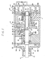
- Figure 1 is longitudinal sectional view of swash plate type refrigerant compressor with a variable displacement mechanism in accordance with an embodiment of a minimum slant angle of the swash plate.
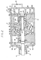
- Figure 2 is a longitudinal sectional view of the swash plate type refrigerant compressor with the variable displacement mechanism in accordance with an embodiment of a maxmun slant angle of swash plate.
- Figure 3 is enlarged cross sectianal view taken along line 4-4 of Figure 1.
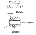
- Figure 4 is enlarged cross sectional view similar Figure 3 of a prior art.
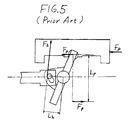
- Figure 5 is an illustrative view of the drive mechanism of showing a hinge coupling mechanism in accordance with a prior art.
- Figure 6 is an illustrative view of the drive mechanism of showing the hinge coupling mechanism in accordance with Figure 1.
- the compressor includes a closed cylinder housing assembly 10 formed by an annular casing 20 provided with cylinder block 11 at one its sides, a hollow portion such as crank chamber 20b, front end plate 23 and rear end plate21.
- Front end plate 23 and valve plate 22b is mounted on the end of opening of annular casing 20 to close the end opening of crank chamber 20b and is fixed on casing 20 by a plurality of bolts(not shown).
- Rear end plate 21 and valve plate 22a are mounted on the other end of casing 20 by a plurality of bolts(not shown) to cover the end position of cylinder block 11.
- An opening 12 is formed in front end plate 23 for receiving drive shaft 24.
- An annular sleeve 13 projects from the front end surface of front end surface of front end plate 23 through bearing 45, which is disposed within cylinder block 11.
- the inner end of drive shaft 24 is provided with a first rotor plate 30 and drive shaft 24 is fixed in rotor plate with a pin( not shown).
- a thrust needle bearing 46 is placed between the inner end surface of front end plate 23 and the adjacent axial end surface of rotor plate 30 to receive the thrust load that acts against rotor plate30 and ensure smooth motion.
- the outer end of drive shaft 24, which extends outwardly from sleeve 14, is drive by the engine of a vehicle through a conventional pulley arrangement.
- drive shaft 24 extends into a second rotor plate 29 rotatably and central bore 20a formed in the center of cylinder block 11 and is rotatabty supported therein by a bearing such as radial needle bearing 47 within actuator 31.
- the inner end of drive shaft 24 is rotatably supported in the inside of actuator 31 and is rotatably disposed in central bore 20.
- Coil spring 32 is surrounds the end of actuator 31 and disposed between actuator 31 and valve plate 22a to push actuator 31 toward outside of drive shaft 24. The recoil strength of coil spring 32 is set to opposite to the inner compression of crank chamber 20b.
- Chamber 39 of rear side of actuator 31 is communicated with control chamber 33 through hole 22a' of valve plate 22a and the movement volume of actuator 31 is adjustable by the inner gas compression of control chamber 33 which is controlled by pressure control valve 35 of pressure control system communicated with discharge chamber 100.
- a second rotor plate 29 includes arm portion 29a projecting axially outwardly from one side surface thereof and forming rectangular hole 29b gained obliquely to drive shaft 24.
- Swash plate includes opening 48 through which drive shaft 24 is disposed and first arm portion 27c and second arm portion27d.
- First arm portion 27c is projected toward first portion 29a of first rotor plate 29 from one side surface thereof.
- Second arm portion 27d is projected toward second arm portion 30a of second rotor plate 30 from one side surface thereof.
- swash plate 27 is connected with rotor plate 29 and rotor plate 30 through a hinge coupling mechanism for rotation in unison with rotor plate 29 and rotor plate 30.
- pin 37b are slidably disposed in rectangular hole 30b and in groove 29b, the sliding motion of pin 37a and pin 37b changes the slant angle of the inclined surface of swash plate27.
- Cylinder block 20 includes a plurality of annularly arranged cylinders 25 into which piston 26 slides.
- a typical arrangement includes may be provided.
- Each piston 26 comprise a double-headed portion slidably disposed within cylinder 25 and connecting portion 26a.
- Semi spherical thrust bearing shoes 28 are disposed between each side surface of connecting portion 26a for sliding along the side surface of swash plate 27.
- the rotation of drive shaft 24 causes swash plate 27 to rotate between bearing shoes 28 and to move the inclined surface axially to the right and left, thereby reciprocating piston 26 within cylinder 25.
- Rear end plate 21 is shaped to define suction chamber 101 and discharge chamber 100.
- Valve plate 22a which together with rear end plate 21 is fastened to the end of cylinder block 20 by bolts( not shown ), is provided with a plurality of valve suction ports 111 connected between suction chamber 101 and respective cylinders 25, and a plurality of valve discharge ports 110 con- nected between discharge chamber 100 and respective cylinder 25.
- Discharge chamber 100 and control chamber 33 are connected by a pressure control system 34 including passage way and control valve 35.
- first arm portion 27c of swash plate 27 and second portion 27d are respectively disposed symmetrical to the center of swash plate 27 two by two and is inserted first arm 29a of first rotor plate 29.
- First arm portion 27c and second arm portion 27d of swash plate are rotatably projected with first arm portion 29a of first rotor plate 29 and second arm portion 30a of second rotor plate 30 through first rectangular hole 29b and second rectangular hole 30b by pin 37a and 37b.
- Pin 37a and pin 37b are fixed to prevent falling out by snap ring 38.
- swash plate 27 is shifted between a position where the inclination angle is large as shown in Figure and a position where the inclination angle is small as shown in Figure 2, while pin 37a and 37b of swash plate 27 is being slid within rectangular hole 29b and second rectangular hole 30b.
- drive shaft 24 is rotated by the engine of a vehicle through the pulley arrangement, and first rotor plate 29 and second rotor plate 30 are rotated together with drive shaft 24.
- the rotation of these plate are transferred to swash plate 27 through the hinge coupling mechanism so that with respect to the rotation of these rotor plate the inclined surface of swash plate 27 moves axially to the right and left.
- Double-headed piston 26 which are operatively connected to swash plate 27 by means of swash plate 27 sliding between bearing shoes 28, therefore reciprocate within cylinder 25.
- the refrigerant gas which is introduced into suction chamber 101 from the fluid inlet port is taken into each cylinder 25 and compressed.
- the compressed refrigerant is discharged to discharge chamber 100 from each cylinder 25 through discharge port 111 and therefrom into an external fluid circuit,for example a cooling circuit through the fluid outlet port.
- pin 37a causes the counter clock wise rotation of first arm 27c of swash plate 27 guide by first rectangular hole 29b.
- the slant angle of swash plate 27 is maximized relate to the vertical plane. This result in the maximum stroke of double headed piston 26 within cylinder 25 which corresponds to normal refrigerated capacity of the compressor.
- swash plate 27 includes arm portion being two by two up and down, and frictionally supported by thereof.
Abstract
Description
- The present invention relates to a variable displacement swash plate type compressor which is particularly available as a refrigerant compressor for an automotive air-conditioning apparatus.
- A swash plate type refrigerant compressor with a variable displacement mechanism suitable for use in an automotive air conditioning system is disclosed in U.S. Patent No.4963074. As disclosed there, a swash plate is provided on a rotary shaft of the compressor so that a change in inclination angle of the slant plate causes the reciprocating stroke of each piston to change.
- A swash plate is connected with rotor plate through a hinge coupling mechanism for rotation in unison with rotor plate. The incline angle of a swash plate is adjustable to vary the stroke length of the double-headed piston.
- The hinge coupling mechanism includes an arm portion projecting axially from outside surface there and a swash plate also second arm portion projecting toward an arm portion of a rotor plate from one side surface thereof. The arm portion overlap each other and connected to one another by a guide pin which extends into a rectangular shaped hole formed through an arm portion of the rotor plate and a pin hole formed through a second arm portion of slant plate. That is, this compressor includes only one hinge coupling mechanism.
- Furthermore, referring to Figure 3, a hinge mechanism is constructed of which only one arm portion of the swash plate and only one arm of rotor plate are slidably connected with one guide pin and one snap pin through the rectangular hole.
- Therefore,referring to Figure 5, the reaction force of piston through a gas compression in cylinder acts against the swash plate and is finally received the hinge coupling mechanism.
- When the reaction force from piston by the gas compression in cylinder is settled Fp. Moment Mp is indicated the product of reaction force Fp by lenght Lp which is distance from both end of the swash plate.
- The axial force of the hinge mechanism is received by moment Mp and against to this moment is indicated Fp , and the distance between the hinge mechanism and the center of swash plate is shown Lp as following equation:


- Such arrangement, the magnitude of force Fh is large compared with force Fp since the value of length Lh is very small compared with length Lp.
- Therefore, the outer peripheral surface of a guide pin and a surface of a rectangular shaped hole of the rotor plate are worn away since the compressor includes only one hinge coupling mechanism and the hinge coupling mechanism is received by the large force of the gas compression during operation of the compressor. As a result, an ability of control of compressor become to be deteriorated and reliability of the adjusting piston stroke.
- Accordingly, a first object of the present invention is to provide a variable capacity type the swash plate compressor having a durable hinged joint between the swash plate and the rotor plate. The variable capacity type the swash plate compressor according to the present invention includes a compressor housing enclosing a crank chamber, a suction chamber and a discharge chamber therein. The compressor housing comprises a cylinder block having a plurality of cylinders formed therethrough. A double-headed pistons slidably fits within each of the cylinders. A driving mechanism is coupled to the pistons for reciprocating the pistons within the cylinders. The driving mechanism includes the drive shaft rotatably supported in the housing, a first rotor plate is frictionally together the drive shaft and second rotor plate is fixed with a penetrated guide pin and rotatabty together a drive shaft. These rotor plates are connected with first arm and second arm of a swash plate which is disposed symmetrical far from each other two by two.
- A hinge coupling mechanism includes these rotor plate and these arm portion of the swash plate. These arm portion of the swash plates and the rotor plates are frictionally connected with a guide pin respectively. The swash plate is supported for rotational and rotational motion of the drive shaft and is respectively connected to the position through bearing shoes. Each piston accomplish reciprocating movement within the cylinder by the rotation of the awash plate and the stroke of piaton is change by the hinge coupling mechanism due to the pressure difference a crank chamber and a control chamber and a suction chamber.
- The control chamber is disposed in a central bore in a cylinder block and includes a actuator which is rotatably disposed in the center bore, furthermore, a coil spring is surrounds the end of actuator and disposed between actuator and valve plate to push the actuator toward outside of the drive shaft. the recoil strength of coil spring is set to opposite to the inner compression of the crank chamber. The control chamber is communicated with a discharge chamber via a control chamber which is device to adjust the pressure between the crank chamber and the control chamber and to adjust the piston stroke.
- In the accompanying drawings:-
- Figure 1 is longitudinal sectional view of swash plate type refrigerant compressor with a variable displacement mechanism in accordance with an embodiment of a minimum slant angle of the swash plate.
- Figure 2 is a longitudinal sectional view of the swash plate type refrigerant compressor with the variable displacement mechanism in accordance with an embodiment of a maxmun slant angle of swash plate.
- Figure 3 is enlarged cross sectianal view taken along line 4-4 of Figure 1.
- Figure 4 is enlarged cross sectional view similar Figure 3 of a prior art.
- Figure 5 is an illustrative view of the drive mechanism of showing a hinge coupling mechanism in accordance with a prior art.
- Figure 6 is an illustrative view of the drive mechanism of showing the hinge coupling mechanism in accordance with Figure 1.
- Referring to Figure 1, an refrigerant compressor according to this invention is shown. The compressor includes a closed
cylinder housing assembly 10 formed by anannular casing 20 provided withcylinder block 11 at one its sides, a hollow portion such ascrank chamber 20b,front end plate 23 and rear end plate21. -
Front end plate 23 andvalve plate 22b is mounted on the end of opening ofannular casing 20 to close the end opening ofcrank chamber 20b and is fixed oncasing 20 by a plurality of bolts(not shown). Rear end plate 21 andvalve plate 22a are mounted on the other end ofcasing 20 by a plurality of bolts(not shown) to cover the end position ofcylinder block 11. Anopening 12 is formed infront end plate 23 for receivingdrive shaft 24. Anannular sleeve 13 projects from the front end surface of front end surface offront end plate 23 throughbearing 45, which is disposed withincylinder block 11. The inner end ofdrive shaft 24 is provided with afirst rotor plate 30 anddrive shaft 24 is fixed in rotor plate with a pin( not shown). - A thrust needle bearing 46 is placed between the inner end surface of
front end plate 23 and the adjacent axial end surface ofrotor plate 30 to receive the thrust load that acts against rotor plate30 and ensure smooth motion. The outer end ofdrive shaft 24, which extends outwardly fromsleeve 14, is drive by the engine of a vehicle through a conventional pulley arrangement. - The inner end of
drive shaft 24 extends into asecond rotor plate 29 rotatably andcentral bore 20a formed in the center ofcylinder block 11 and is rotatabty supported therein by a bearing such as radial needle bearing 47 withinactuator 31. The inner end ofdrive shaft 24 is rotatably supported in the inside ofactuator 31 and is rotatably disposed incentral bore 20.Coil spring 32 is surrounds the end ofactuator 31 and disposed betweenactuator 31 andvalve plate 22a to pushactuator 31 toward outside ofdrive shaft 24. The recoil strength ofcoil spring 32 is set to opposite to the inner compression ofcrank chamber 20b. -
Chamber 39 of rear side ofactuator 31 is communicated withcontrol chamber 33 throughhole 22a' ofvalve plate 22a and the movement volume ofactuator 31 is adjustable by the inner gas compression ofcontrol chamber 33 which is controlled bypressure control valve 35 of pressure control system communicated withdischarge chamber 100. Asecond rotor plate 29 includesarm portion 29a projecting axially outwardly from one side surface thereof and formingrectangular hole 29b gained obliquely to driveshaft 24. Swash plate includes opening 48 through which driveshaft 24 is disposed andfirst arm portion 27c and second arm portion27d. -
First arm portion 27c is projected towardfirst portion 29a offirst rotor plate 29 from one side surface thereof.Second arm portion 27d is projected towardsecond arm portion 30a ofsecond rotor plate 30 from one side surface thereof. - In this manner,
swash plate 27 is connected withrotor plate 29 androtor plate 30 through a hinge coupling mechanism for rotation in unison withrotor plate 29 androtor plate 30. - In this construction,
pin 37b are slidably disposed inrectangular hole 30b and ingroove 29b, the sliding motion ofpin 37a andpin 37b changes the slant angle of the inclined surface of swash plate27. -
Cylinder block 20 includes a plurality of annularly arrangedcylinders 25 into whichpiston 26 slides. A typical arrangement includes may be provided. Eachpiston 26 comprise a double-headed portion slidably disposed withincylinder 25 and connectingportion 26a. - Semi spherical
thrust bearing shoes 28 are disposed between each side surface of connectingportion 26a for sliding along the side surface ofswash plate 27. The rotation ofdrive shaft 24 causesswash plate 27 to rotate betweenbearing shoes 28 and to move the inclined surface axially to the right and left, thereby reciprocatingpiston 26 withincylinder 25. - Rear end plate 21 is shaped to define
suction chamber 101 anddischarge chamber 100.Valve plate 22a, which together with rear end plate 21 is fastened to the end ofcylinder block 20 by bolts( not shown ), is provided with a plurality ofvalve suction ports 111 connected betweensuction chamber 101 andrespective cylinders 25, and a plurality ofvalve discharge ports 110 con- nected betweendischarge chamber 100 andrespective cylinder 25.Discharge chamber 100 andcontrol chamber 33 are connected by apressure control system 34 including passage way and controlvalve 35. - Referring to Figure 3,
first arm portion 27c ofswash plate 27 andsecond portion 27d are respectively disposed symmetrical to the center ofswash plate 27 two by two and is insertedfirst arm 29a offirst rotor plate 29.First arm portion 27c andsecond arm portion 27d of swash plate are rotatably projected withfirst arm portion 29a offirst rotor plate 29 andsecond arm portion 30a ofsecond rotor plate 30 through firstrectangular hole 29b and secondrectangular hole 30b bypin Pin 37a andpin 37b are fixed to prevent falling out bysnap ring 38. - With such an arrangement,
swash plate 27 is shifted between a position where the inclination angle is large as shown in Figure and a position where the inclination angle is small as shown in Figure 2, whilepin swash plate 27 is being slid withinrectangular hole 29b and secondrectangular hole 30b. - In operation, drive
shaft 24 is rotated by the engine of a vehicle through the pulley arrangement, andfirst rotor plate 29 andsecond rotor plate 30 are rotated together withdrive shaft 24. The rotation of these plate are transferred toswash plate 27 through the hinge coupling mechanism so that with respect to the rotation of these rotor plate the inclined surface ofswash plate 27 moves axially to the right and left. Double-headedpiston 26 which are operatively connected toswash plate 27 by means ofswash plate 27 sliding between bearingshoes 28, therefore reciprocate withincylinder 25. As double headedpiston 26 reciprocate, the refrigerant gas which is introduced intosuction chamber 101 from the fluid inlet port is taken into eachcylinder 25 and compressed. The compressed refrigerant is discharged to dischargechamber 100 from eachcylinder 25 throughdischarge port 111 and therefrom into an external fluid circuit,for example a cooling circuit through the fluid outlet port. - When the refrigerant capacity of a compressor is decreased, the pressure in
control chamber 33 is decreased by closingcontrol valve 35, the pressure incontrol chamber 20b become to be smaller than the integrated pressure of control chamber and the recoil strength ofcoil spring 32. Thereby, actuator 31 frictionally slides towardvalve plate 22a. Thereby,first rotor plate 29 is moved towardactuator 31 by the pressure incrank chamber 20b. - As a result,
pin 37a causes the counter clock wise rotation offirst arm 27c ofswash plate 27 guide by firstrectangular hole 29b. - Also, the above action causes the counterclockwise rotation of
second arm 27d ofswash plate 27 andpin 37b slides downward throughgroove gain 30b. - As a result, the slant angle of
swash plate 27 is minimized related to the vertical plane. This results in the minimum stroke of double-headedpiston 26 withincylinder 25 which corresponds to the normal refrigerant capacity of the compressor. - On the other hand, when the refrigerant capacity of a compressor is increased, the pressure in
control chamber 33 is increased by openingcontrol valve 35, the integrated force of the pressure inchamber 33 and the recoil of coil spring32 become to be larger than the pressure incrank chamber 20b, theactuator 31 frictionally slides towardswash plate 27 andfirst rotor plate 29 is moved towardsecond rotor plate 30 byactuator 31. As a result,pin 37a causes the clock wise rotation offirst arm 27c ofswash plate 27 sliding in firstrectangular hole 29b, Also, the above action causes the clockwise rotation ofsecond arm 27d ofswash 27 andpin 37b slides upward guided bygroove gain 30b. - As a result, the slant angle of
swash plate 27 is maximized relate to the vertical plane. This result in the maximum stroke of double headedpiston 26 withincylinder 25 which corresponds to normal refrigerated capacity of the compressor. - Therefore, referring to Figure 6, the reaction of
piston 27 stroke through gas compression incylinder 25 acts againstswash plate 27 and is finally received the hinge coupling mechanism. The moment caused by the rotation force acting onpiston 26 thus acts against the hinge coupling mechanism to cause clockwise rotation as center ofswash plate 27. - When the reaction force from piston by gas compression and the moment of
swash plate 27 subject by the force of both side piston in casing is respectively Fp,Mp', and the distance between the apex and the end of swash plate is settled Lp', Moment Mp' is the product of force Fp' by distance Lp' as following equation.
- Also, when the force of two hinge mechanisms subjected by from
swash plate 27 and the distance between the first hinge coupling mechanism and the second hinge coupling mechanism are settled respectively Fh',Lh', and the moment of hinge coupling mechanism is settled Mh',
- Moment Mp' should be balance with moment Mh'. As following equations formulate.


- Such arrangement, the magnitude of force Fh' is very small compared with force Fp since the value of distance Lh' is very large compare with Lp'.
- Furthemore, two hinge mechanism could be more securely supported against the large moment of reaction compression from pistons,since
swash plate 27 includes arm portion being two by two up and down, and frictionally supported by thereof.
Claims (1)
- A swash plate type compressor comprising:
a cylinder block having a plurality of cylinder chambers therein;
a drive shaft rotatably supported in said cylinder block;
a swash plate tiltably connected to said drive shaft and adapted to be rotated together with said drive shaft;
pistons slidably received in said cylinder chambers and adapted to be reciprocally moved in said cylinder chambers in accordance with an oscillatory motion of said swash plate;
a support portion disposed coaxially with said drive shaft and supporting a central portion of said swash plate rotatably and tiltably; and
a spool for driving said support portion axially of said drive shaft to move said central portion of said swash plate axially of said drive shaft, the improvement comprising:
said support portion including a first arm portion radially extending therefrom, said swash plate including a second and third arm portions axially extending from the opposite end sur- faces thereof, respectively, said drive shaft including a fourth arm portion radially extending therefrom in the opposite direction of said first arm portion, said first and second arm portions hingedly connected and said third and fourth arm portions hingedly connected to change the angle of tilt of said swash plate, whereby the strokes of reciprocatory movements of said pistons in said cylinder chambers are changed.
Applications Claiming Priority (2)
| Application Number | Priority Date | Filing Date | Title |
|---|---|---|---|
| JP335076/91 | 1991-12-18 | ||
| JP3335076A JPH05172052A (en) | 1991-12-18 | 1991-12-18 | Variable displacement swash plate type compressor |
Publications (2)
| Publication Number | Publication Date |
|---|---|
| EP0550228A1 true EP0550228A1 (en) | 1993-07-07 |
| EP0550228B1 EP0550228B1 (en) | 1995-07-26 |
Family
ID=18284498
Family Applications (1)
| Application Number | Title | Priority Date | Filing Date |
|---|---|---|---|
| EP92311608A Expired - Lifetime EP0550228B1 (en) | 1991-12-18 | 1992-12-18 | Swash plate type compressor with variable displacemnet mechanism |
Country Status (8)
| Country | Link |
|---|---|
| US (1) | US5259736A (en) |
| EP (1) | EP0550228B1 (en) |
| JP (1) | JPH05172052A (en) |
| KR (1) | KR930013480A (en) |
| CN (1) | CN1031008C (en) |
| AU (1) | AU658036B2 (en) |
| CA (1) | CA2085771C (en) |
| DE (1) | DE69203709T2 (en) |
Cited By (11)
| Publication number | Priority date | Publication date | Assignee | Title |
|---|---|---|---|---|
| BE1008749A3 (en) * | 1994-05-16 | 1996-07-02 | Toyoda Automatic Loom Works | Method and apparatus for compressed air supply. |
| EP0907020A1 (en) * | 1997-01-24 | 1999-04-07 | Kabushiki Kaisha Toyoda Jidoshokki Seisakusho | Variable displacement swash plate compressor having an improved swash plate supporting means |
| EP0911522A3 (en) * | 1997-10-21 | 2001-06-06 | Calsonic Kansei Corporation | Swash plate type compressor |
| US6638372B1 (en) | 1990-12-18 | 2003-10-28 | Advanced Cardiovascular Systems, Inc. | Superelastic guiding member |
| EP2816230A3 (en) * | 2013-06-20 | 2015-08-12 | Kabushiki Kaisha Toyota Jidoshokki | Variable displacement swash plate type compressor |
| EP3026264A1 (en) * | 2014-11-27 | 2016-06-01 | Kabushiki Kaisha Toyota Jidoshokki | Variable displacement swash-plate compressor |
| EP2728184A3 (en) * | 2012-11-05 | 2017-03-01 | Kabushiki Kaisha Toyota Jidoshokki | Swash plate type variable displacement compressor |
| EP2728183A3 (en) * | 2012-11-05 | 2017-03-01 | Kabushiki Kaisha Toyota Jidoshokki | Swash plate type variable displacement compressor |
| EP2728182A3 (en) * | 2012-11-05 | 2017-03-01 | Kabushiki Kaisha Toyota Jidoshokki | Swash plate type variable displacement compressor |
| EP2728185A3 (en) * | 2012-11-05 | 2017-03-01 | Kabushiki Kaisha Toyota Jidoshokki | Swash plate type variable displacement compressor |
| EP2728186A3 (en) * | 2012-11-05 | 2017-03-01 | Kabushiki Kaisha Toyota Jidoshokki | Swash plate type variable displacement compressor |
Families Citing this family (50)
| Publication number | Priority date | Publication date | Assignee | Title |
|---|---|---|---|---|
| JPH05312144A (en) * | 1992-05-08 | 1993-11-22 | Sanden Corp | Variable displacement swash plate type compressor |
| JP3042650B2 (en) * | 1992-11-26 | 2000-05-15 | サンデン株式会社 | Swash plate compressor |
| US5529461A (en) * | 1993-12-27 | 1996-06-25 | Kabushiki Kaisha Toyoda Jidoshokki Seisakusho | Piston type variable displacement compressor |
| US5603610A (en) * | 1993-12-27 | 1997-02-18 | Kabushiki Kaisha Toyoda Jidoshokki Seisakusho | Clutchless piston type variable displacement compressor |
| US5584670A (en) * | 1994-04-15 | 1996-12-17 | Kabushiki Kaisha Toyoda Jidoshokki Seisakusho | Piston type variable displacement compressor |
| JP4007637B2 (en) * | 1997-03-31 | 2007-11-14 | サンデン株式会社 | Variable capacity compressor |
| JP4051134B2 (en) | 1998-06-12 | 2008-02-20 | サンデン株式会社 | Capacity control valve mechanism of variable capacity compressor |
| JP2000205127A (en) * | 1998-11-11 | 2000-07-25 | Sanden Corp | Compressor |
| KR20000060900A (en) * | 1999-03-20 | 2000-10-16 | 신영주 | Full stroke position setting mechanism for variable capacity swash plate compressors |
| US6210124B1 (en) | 2000-01-27 | 2001-04-03 | Ford Global Technologies, Inc. | Variable swash plate compressor |
| US6354809B1 (en) | 2000-01-27 | 2002-03-12 | Ford Global Technologies, Inc. | Variable swash plate compressor |
| JP2002147348A (en) | 2000-11-08 | 2002-05-22 | Sanden Corp | Variable displacement swash plate type compressor |
| JP4332294B2 (en) | 2000-12-18 | 2009-09-16 | サンデン株式会社 | Manufacturing method of single-head swash plate compressor |
| US7318709B2 (en) * | 2003-08-27 | 2008-01-15 | Haldex Brake Corporation | Pump valve assembly |
| DE102005039199A1 (en) * | 2005-08-18 | 2007-03-08 | Valeo Compressor Europe Gmbh | axial piston |
| US7455009B2 (en) * | 2006-06-09 | 2008-11-25 | Visteon Global Technologies, Inc. | Hinge for a variable displacement compressor |
| JP4974927B2 (en) * | 2008-02-26 | 2012-07-11 | カルソニックカンセイ株式会社 | Swash plate compressor |
| EP2916002B1 (en) | 2012-11-05 | 2017-05-17 | Kabushiki Kaisha Toyota Jidoshokki | Variable displacement swash-plate compressor |
| DE112014001700B4 (en) * | 2013-03-27 | 2017-11-02 | Kabushiki Kaisha Toyota Jidoshokki | Swashplate compressor with variable adjustment |
| JP5983657B2 (en) * | 2014-02-26 | 2016-09-06 | 株式会社豊田自動織機 | Variable capacity swash plate compressor |
| JP5949626B2 (en) * | 2013-03-27 | 2016-07-13 | 株式会社豊田自動織機 | Variable capacity swash plate compressor |
| JP6083291B2 (en) * | 2013-03-27 | 2017-02-22 | 株式会社豊田自動織機 | Variable capacity swash plate compressor |
| JP6079379B2 (en) | 2013-03-29 | 2017-02-15 | 株式会社豊田自動織機 | Variable capacity swash plate compressor |
| US9624919B2 (en) | 2013-03-29 | 2017-04-18 | Kabushiki Kaisha Toyota Jidoshokki | Variable displacement swash plate type compressor |
| DE112014001751T5 (en) * | 2013-03-29 | 2015-12-17 | Kabushiki Kaisha Toyota Jidoshokki | Variable displacement swash plate type compressor |
| WO2014157208A1 (en) * | 2013-03-29 | 2014-10-02 | 株式会社豊田自動織機 | Variable displacement swash-plate compressor |
| JP6115258B2 (en) * | 2013-03-29 | 2017-04-19 | 株式会社豊田自動織機 | Double-head piston type swash plate compressor |
| JP6032146B2 (en) | 2013-07-16 | 2016-11-24 | 株式会社豊田自動織機 | Double-head piston type swash plate compressor |
| JP6107528B2 (en) * | 2013-08-08 | 2017-04-05 | 株式会社豊田自動織機 | Variable capacity swash plate compressor |
| JP6037028B2 (en) * | 2013-09-11 | 2016-11-30 | 株式会社豊田自動織機 | Variable capacity swash plate compressor |
| JP6015614B2 (en) * | 2013-09-25 | 2016-10-26 | 株式会社豊田自動織機 | Variable capacity swash plate compressor |
| JP6094456B2 (en) * | 2013-10-31 | 2017-03-15 | 株式会社豊田自動織機 | Variable capacity swash plate compressor |
| JP6146263B2 (en) | 2013-11-06 | 2017-06-14 | 株式会社豊田自動織機 | Variable capacity swash plate compressor |
| JP6171875B2 (en) | 2013-11-13 | 2017-08-02 | 株式会社豊田自動織機 | Variable capacity swash plate compressor |
| KR101510349B1 (en) * | 2013-12-13 | 2015-04-16 | 현대자동차 주식회사 | Variable capacity compressor |
| KR102013598B1 (en) * | 2014-03-07 | 2019-08-23 | 한온시스템 주식회사 | Device for adjusting swash plate angle in variable displacement swash plate type compressor |
| JP6264105B2 (en) * | 2014-03-10 | 2018-01-24 | 株式会社豊田自動織機 | Variable capacity swash plate compressor |
| JP6229565B2 (en) | 2014-03-20 | 2017-11-15 | 株式会社豊田自動織機 | Variable capacity swash plate compressor |
| JP6194830B2 (en) | 2014-03-24 | 2017-09-13 | 株式会社豊田自動織機 | Variable capacity swash plate compressor |
| JP6287483B2 (en) * | 2014-03-28 | 2018-03-07 | 株式会社豊田自動織機 | Variable capacity swash plate compressor |
| JP6179439B2 (en) | 2014-03-28 | 2017-08-16 | 株式会社豊田自動織機 | Variable capacity swash plate compressor |
| JP6194836B2 (en) | 2014-03-28 | 2017-09-13 | 株式会社豊田自動織機 | Variable capacity swash plate compressor |
| JP6194837B2 (en) | 2014-03-28 | 2017-09-13 | 株式会社豊田自動織機 | Variable capacity swash plate compressor |
| JP6191527B2 (en) | 2014-03-28 | 2017-09-06 | 株式会社豊田自動織機 | Variable capacity swash plate compressor |
| JP6179438B2 (en) * | 2014-03-28 | 2017-08-16 | 株式会社豊田自動織機 | Variable capacity swash plate compressor |
| JP2016014343A (en) | 2014-07-01 | 2016-01-28 | 株式会社豊田自動織機 | Variable displacement swash plate compressor |
| JP6256236B2 (en) | 2014-07-22 | 2018-01-10 | 株式会社豊田自動織機 | Variable capacity swash plate compressor |
| JP2016151188A (en) * | 2015-02-16 | 2016-08-22 | 株式会社豊田自動織機 | Variable displacement swash plate compressor |
| KR101926923B1 (en) | 2016-11-02 | 2018-12-07 | 현대자동차주식회사 | Air-conditioner compressor for vehicle |
| CN109798235B (en) * | 2019-03-07 | 2024-01-23 | 陕西航天泵阀科技集团有限公司 | Energy exchange pump |
Citations (2)
| Publication number | Priority date | Publication date | Assignee | Title |
|---|---|---|---|---|
| US2889781A (en) * | 1954-11-30 | 1959-06-09 | Sabre Res Corp | Fuel pump |
| FR2461813A1 (en) * | 1979-07-20 | 1981-02-06 | Renon Paul | Piston engine with variable torque - has swash plate on central splined shaft carrying piston rods |
Family Cites Families (19)
| Publication number | Priority date | Publication date | Assignee | Title |
|---|---|---|---|---|
| US3062020A (en) * | 1960-11-18 | 1962-11-06 | Gen Motors Corp | Refrigerating apparatus with compressor output modulating means |
| SU197708A1 (en) * | 1966-03-23 | 1973-01-08 | ALL-UNION ISH.-uul - • 'YUK''YY <(.?> &'? 3! THihl ^ it-Abfr: '.- EUi.'tiB ^' - | €: LIO ^ TKA (TERL10 | |
| US3861829A (en) * | 1973-04-04 | 1975-01-21 | Borg Warner | Variable capacity wobble plate compressor |
| US4077269A (en) * | 1976-02-26 | 1978-03-07 | Lang Research Corporation | Variable displacement and/or variable compression ratio piston engine |
| US4175915A (en) * | 1978-04-27 | 1979-11-27 | General Motors Corporation | Drive shaft lug for variable displacement compressor |
| US4229144A (en) * | 1978-12-07 | 1980-10-21 | Deere & Company | Feedback shaft extending between swashplate and displacement control valve |
| US4448154A (en) * | 1979-04-30 | 1984-05-15 | Paradox International, Incorporated | Internal combustion engine |
| US4433596A (en) * | 1980-03-11 | 1984-02-28 | Joseph Scalzo | Wabbler plate engine mechanisms |
| US4381647A (en) * | 1980-09-12 | 1983-05-03 | Caterpillar Tractor Co. | Load-plus valve for variable displacement pumps |
| US4425837A (en) * | 1981-09-28 | 1984-01-17 | General Motors Corporation | Variable displacement axial piston machine |
| JPS60175783A (en) * | 1984-02-21 | 1985-09-09 | Sanden Corp | Variable capacity swash plate compressor |
| US4674957A (en) * | 1984-12-22 | 1987-06-23 | Kabushiki Kaisha Toyoda Jidoshokki Seisakusho | Control mechanism for variable displacement swash plate type compressor |
| CA1237294A (en) * | 1986-03-27 | 1988-05-31 | Joseph Scalzo | Wobble plate engine stabiliser mechanism |
| US4886423A (en) * | 1986-09-02 | 1989-12-12 | Nippon Soken, Inc. | Variable displacement swash-plate type compressor |
| JPH0733822B2 (en) * | 1986-09-03 | 1995-04-12 | 株式会社日立製作所 | Variable capacity compressor |
| JPS63205473A (en) * | 1987-02-19 | 1988-08-24 | Sanden Corp | Swash plate type variable displacement compressor |
| JPS6477771A (en) * | 1987-09-18 | 1989-03-23 | Hitachi Ltd | Variable delivery compressor |
| JPH02104324A (en) * | 1988-10-14 | 1990-04-17 | Asahi Chem Ind Co Ltd | Pack filter for vacuum cleaner |
| US5055004A (en) * | 1990-05-23 | 1991-10-08 | General Motors Corporation | Stroke control assembly for a variable displacement compressor |
-
1991
- 1991-12-18 JP JP3335076A patent/JPH05172052A/en active Pending
-
1992
- 1992-12-16 AU AU30295/92A patent/AU658036B2/en not_active Ceased
- 1992-12-17 KR KR1019920024568A patent/KR930013480A/en active IP Right Grant
- 1992-12-18 CA CA002085771A patent/CA2085771C/en not_active Expired - Fee Related
- 1992-12-18 EP EP92311608A patent/EP0550228B1/en not_active Expired - Lifetime
- 1992-12-18 CN CN92115322A patent/CN1031008C/en not_active Expired - Lifetime
- 1992-12-18 DE DE69203709T patent/DE69203709T2/en not_active Expired - Fee Related
- 1992-12-18 US US07/992,734 patent/US5259736A/en not_active Expired - Fee Related
Patent Citations (2)
| Publication number | Priority date | Publication date | Assignee | Title |
|---|---|---|---|---|
| US2889781A (en) * | 1954-11-30 | 1959-06-09 | Sabre Res Corp | Fuel pump |
| FR2461813A1 (en) * | 1979-07-20 | 1981-02-06 | Renon Paul | Piston engine with variable torque - has swash plate on central splined shaft carrying piston rods |
Cited By (14)
| Publication number | Priority date | Publication date | Assignee | Title |
|---|---|---|---|---|
| US6638372B1 (en) | 1990-12-18 | 2003-10-28 | Advanced Cardiovascular Systems, Inc. | Superelastic guiding member |
| BE1008749A3 (en) * | 1994-05-16 | 1996-07-02 | Toyoda Automatic Loom Works | Method and apparatus for compressed air supply. |
| EP0907020A1 (en) * | 1997-01-24 | 1999-04-07 | Kabushiki Kaisha Toyoda Jidoshokki Seisakusho | Variable displacement swash plate compressor having an improved swash plate supporting means |
| EP0907020A4 (en) * | 1997-01-24 | 2001-03-28 | Kk | Variable displacement swash plate compressor having an improved swash plate supporting means |
| EP0911522A3 (en) * | 1997-10-21 | 2001-06-06 | Calsonic Kansei Corporation | Swash plate type compressor |
| EP2728184A3 (en) * | 2012-11-05 | 2017-03-01 | Kabushiki Kaisha Toyota Jidoshokki | Swash plate type variable displacement compressor |
| EP2728183A3 (en) * | 2012-11-05 | 2017-03-01 | Kabushiki Kaisha Toyota Jidoshokki | Swash plate type variable displacement compressor |
| EP2728182A3 (en) * | 2012-11-05 | 2017-03-01 | Kabushiki Kaisha Toyota Jidoshokki | Swash plate type variable displacement compressor |
| EP2728185A3 (en) * | 2012-11-05 | 2017-03-01 | Kabushiki Kaisha Toyota Jidoshokki | Swash plate type variable displacement compressor |
| EP2728186A3 (en) * | 2012-11-05 | 2017-03-01 | Kabushiki Kaisha Toyota Jidoshokki | Swash plate type variable displacement compressor |
| US9284954B2 (en) | 2013-06-20 | 2016-03-15 | Kabushiki Kaisha Toyota Jidoshokki | Variable displacement swash plate type compressor |
| EP2816230A3 (en) * | 2013-06-20 | 2015-08-12 | Kabushiki Kaisha Toyota Jidoshokki | Variable displacement swash plate type compressor |
| EP3026264A1 (en) * | 2014-11-27 | 2016-06-01 | Kabushiki Kaisha Toyota Jidoshokki | Variable displacement swash-plate compressor |
| CN105649920A (en) * | 2014-11-27 | 2016-06-08 | 株式会社丰田自动织机 | Variable displacement swash-plate compressor |
Also Published As
| Publication number | Publication date |
|---|---|
| CN1031008C (en) | 1996-02-14 |
| US5259736A (en) | 1993-11-09 |
| CN1075778A (en) | 1993-09-01 |
| JPH05172052A (en) | 1993-07-09 |
| AU3029592A (en) | 1993-06-24 |
| KR930013480A (en) | 1993-07-21 |
| DE69203709D1 (en) | 1995-08-31 |
| DE69203709T2 (en) | 1996-04-11 |
| EP0550228B1 (en) | 1995-07-26 |
| CA2085771C (en) | 1995-10-24 |
| AU658036B2 (en) | 1995-03-30 |
| CA2085771A1 (en) | 1993-06-19 |
Similar Documents
| Publication | Publication Date | Title |
|---|---|---|
| EP0550228B1 (en) | Swash plate type compressor with variable displacemnet mechanism | |
| EP0568944B1 (en) | Swash plate type compressor with variable displacement mechanism | |
| US4632640A (en) | Wobble plate type compressor with a capacity adjusting mechanism | |
| US5382139A (en) | Guiding mechanism for reciprocating piston of piston type compressor | |
| EP0908623B1 (en) | Reciprocating pistons of piston-type compressor | |
| US5765464A (en) | Reciprocating pistons of piston-type compressor | |
| US4880360A (en) | Variable displacement compressor with biased inclined member | |
| US5174728A (en) | Variable capacity swash plate type compressor | |
| US5615599A (en) | Guiding mechanism for reciprocating piston of piston-type compressor | |
| EP1368568B1 (en) | Axial piston compressor with an axel swashplate actuator | |
| US4960367A (en) | Slant plate type compressor with variable displacement mechanism | |
| US20010007635A1 (en) | Electric type swash plate compressor | |
| US4948343A (en) | Slant-plate type compressor with adjustably positionable drive shaft | |
| EP1111235B1 (en) | Hinge for a swash plate of a variable capacity compressor | |
| US5252032A (en) | Variable capacity swash plate type compressor | |
| EP0809024B1 (en) | Reciprocating pistons of piston type compressor | |
| EP0867617B1 (en) | Variable capacity swash plate compressor | |
| US5255569A (en) | Slant plate type compressor with variable displacement mechanism | |
| US4865523A (en) | Wobble plate compressor with variable displacement mechanism | |
| JPH0819904B2 (en) | Variable capacity swash plate type compressor | |
| US5364232A (en) | Variable displacement compressor | |
| EP0318976A1 (en) | Slant plate type compressor with variable displacement mechanism | |
| JP3084377B2 (en) | Compressor and single-ended piston for use in it | |
| US6350106B1 (en) | Variable displacement compressor with capacity control mechanism | |
| US6378417B1 (en) | Swash plate compressor in which an opening edge of each cylinder bore has a plurality of chamferred portions |
Legal Events
| Date | Code | Title | Description |
|---|---|---|---|
| PUAI | Public reference made under article 153(3) epc to a published international application that has entered the european phase |
Free format text: ORIGINAL CODE: 0009012 |
|
| AK | Designated contracting states |
Kind code of ref document: A1 Designated state(s): DE FR GB IT SE |
|
| 17P | Request for examination filed |
Effective date: 19940105 |
|
| 17Q | First examination report despatched |
Effective date: 19941122 |
|
| GRAA | (expected) grant |
Free format text: ORIGINAL CODE: 0009210 |
|
| AK | Designated contracting states |
Kind code of ref document: B1 Designated state(s): DE FR GB IT SE |
|
| ET | Fr: translation filed | ||
| ITF | It: translation for a ep patent filed |
Owner name: JACOBACCI & PERANI S.P.A. |
|
| REF | Corresponds to: |
Ref document number: 69203709 Country of ref document: DE Date of ref document: 19950831 |
|
| PLBE | No opposition filed within time limit |
Free format text: ORIGINAL CODE: 0009261 |
|
| STAA | Information on the status of an ep patent application or granted ep patent |
Free format text: STATUS: NO OPPOSITION FILED WITHIN TIME LIMIT |
|
| 26N | No opposition filed | ||
| PGFP | Annual fee paid to national office [announced via postgrant information from national office to epo] |
Ref country code: SE Payment date: 19971218 Year of fee payment: 6 |
|
| PG25 | Lapsed in a contracting state [announced via postgrant information from national office to epo] |
Ref country code: SE Free format text: LAPSE BECAUSE OF NON-PAYMENT OF DUE FEES Effective date: 19981219 |
|
| PGFP | Annual fee paid to national office [announced via postgrant information from national office to epo] |
Ref country code: DE Payment date: 20001211 Year of fee payment: 9 |
|
| PGFP | Annual fee paid to national office [announced via postgrant information from national office to epo] |
Ref country code: FR Payment date: 20001212 Year of fee payment: 9 |
|
| PGFP | Annual fee paid to national office [announced via postgrant information from national office to epo] |
Ref country code: GB Payment date: 20001213 Year of fee payment: 9 |
|
| PG25 | Lapsed in a contracting state [announced via postgrant information from national office to epo] |
Ref country code: GB Free format text: LAPSE BECAUSE OF NON-PAYMENT OF DUE FEES Effective date: 20011218 |
|
| REG | Reference to a national code |
Ref country code: GB Ref legal event code: IF02 |
|
| PG25 | Lapsed in a contracting state [announced via postgrant information from national office to epo] |
Ref country code: DE Free format text: LAPSE BECAUSE OF NON-PAYMENT OF DUE FEES Effective date: 20020702 |
|
| GBPC | Gb: european patent ceased through non-payment of renewal fee |
Effective date: 20011218 |
|
| PG25 | Lapsed in a contracting state [announced via postgrant information from national office to epo] |
Ref country code: FR Free format text: LAPSE BECAUSE OF NON-PAYMENT OF DUE FEES Effective date: 20020830 |
|
| REG | Reference to a national code |
Ref country code: FR Ref legal event code: ST |
|
| PG25 | Lapsed in a contracting state [announced via postgrant information from national office to epo] |
Ref country code: IT Free format text: LAPSE BECAUSE OF NON-PAYMENT OF DUE FEES;WARNING: LAPSES OF ITALIAN PATENTS WITH EFFECTIVE DATE BEFORE 2007 MAY HAVE OCCURRED AT ANY TIME BEFORE 2007. THE CORRECT EFFECTIVE DATE MAY BE DIFFERENT FROM THE ONE RECORDED. Effective date: 20051218 |