EP0548485A2 - Surgical reamer assembly - Google Patents
Surgical reamer assembly Download PDFInfo
- Publication number
- EP0548485A2 EP0548485A2 EP92117695A EP92117695A EP0548485A2 EP 0548485 A2 EP0548485 A2 EP 0548485A2 EP 92117695 A EP92117695 A EP 92117695A EP 92117695 A EP92117695 A EP 92117695A EP 0548485 A2 EP0548485 A2 EP 0548485A2
- Authority
- EP
- European Patent Office
- Prior art keywords
- planar
- adaptor
- reamer
- base support
- assembly
- Prior art date
- Legal status (The legal status is an assumption and is not a legal conclusion. Google has not performed a legal analysis and makes no representation as to the accuracy of the status listed.)
- Granted
Links
Images

Classifications
-
- A—HUMAN NECESSITIES
- A61—MEDICAL OR VETERINARY SCIENCE; HYGIENE
- A61B—DIAGNOSIS; SURGERY; IDENTIFICATION
- A61B17/00—Surgical instruments, devices or methods, e.g. tourniquets
- A61B17/16—Bone cutting, breaking or removal means other than saws, e.g. Osteoclasts; Drills or chisels for bones; Trepans
- A61B17/1662—Bone cutting, breaking or removal means other than saws, e.g. Osteoclasts; Drills or chisels for bones; Trepans for particular parts of the body
- A61B17/1664—Bone cutting, breaking or removal means other than saws, e.g. Osteoclasts; Drills or chisels for bones; Trepans for particular parts of the body for the hip
- A61B17/1668—Bone cutting, breaking or removal means other than saws, e.g. Osteoclasts; Drills or chisels for bones; Trepans for particular parts of the body for the hip for the upper femur
-
- A—HUMAN NECESSITIES
- A61—MEDICAL OR VETERINARY SCIENCE; HYGIENE
- A61B—DIAGNOSIS; SURGERY; IDENTIFICATION
- A61B17/00—Surgical instruments, devices or methods, e.g. tourniquets
- A61B17/16—Bone cutting, breaking or removal means other than saws, e.g. Osteoclasts; Drills or chisels for bones; Trepans
- A61B17/1659—Surgical rasps, files, planes, or scrapers
-
- A—HUMAN NECESSITIES
- A61—MEDICAL OR VETERINARY SCIENCE; HYGIENE
- A61B—DIAGNOSIS; SURGERY; IDENTIFICATION
- A61B17/00—Surgical instruments, devices or methods, e.g. tourniquets
- A61B2017/0046—Surgical instruments, devices or methods, e.g. tourniquets with a releasable handle; with handle and operating part separable
Definitions
- the present invention relates to a surgical reamer assembly. More specifically, the reamer assembly is used for cutting a planar bone surface.
- planar reamers for reaming or cutting a flat, planar surface on bone is well known in the orthopaedic industry.
- One such type of planar reamer is used for reaming the calcar bone of a femur to match the undersurface of an extending collar on a collared femoral hip prosthesis.
- Such a planar reamer is shown in Fig. 7 of U.S. Patent 5,019,108 to Bertin et al. which shows a calcar reamer 40 with a pin 41 protruding from cutting surface 43.
- the pin 41 fits directly into hole 35 of rasp 30 (of Fig. 6) functioning as a pivot.
- pivoting the surface 43 about pin 41 planes the femoral bone to provide a flat bone contact to mate with the flat undersurface 18 of collar 17 of the hip implant 10.
- FIG. 9 shows a planar reamer 97 which fits directly over protruding pin 93 to ream a flat surface on the bone.
- Fig. 10 shows an alternate planing tool 99 with an integral post 103 depending therefrom which is inserted in an opening in barrel 15 to cut a planar surface.
- the planar reaming surface either has a pivot post protruding directly therefrom for fitting in a hole on a supporting surface or the planar reaming surface has a hole therein for fitting directly over a protruding post.
- the present invention provides a reamer assembly for cutting a planar bone surface.
- the surgical reamer assembly enables the angle or the level of the cutting of the planar reamer to be adjusted. This adjustment is advantageously provided by the use of an adaptor which is positioned between the base support on the planar reamer instrument.
- Figs. 1-5 illustrate a particularly advantageous embodiment of the surgical reamer assembly of the present invention
- Figs. 6-11 illustrate an alternate advantageous embodiment of the invention.
- the invention will be described with reference to a surgical reamer assembly for planing a flat bone surface for mating with the flat undersurface of an extending collar on a collared femoral hip prosthesis.
- the principles of the invention are applicable to a surgical reamer assembly for planing any suitable flat bone surface.
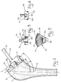
- the embodiment of Figs. 1-5 illustrate surgical reamer assembly 1.
- the assembly 1 includes a base support 10, a planar reamer 30, and an adaptor 50 for positioning between support 10 and reamer 30.
- the base support 10, as shown, may be a rasp cutter for forming a cavity 8 in the femoral bone 7, as shown in Fig. 1.
- the base support 10 in Fig. 1 is shown positioned in the femur 7. It is desired to cut or ream the femoral bone 7 to provide a flat planar bone surface 9 for mating with the flat undersurface of a collar on a corresponding collared femoral hip prosthesis (not shown).
- the base support 10 has a proximal planar surface 11 which is oriented at a first angle 3 to reference axis A.
- Reference axis A may suitably be the main axis of the elongated base support 10.
- the first angle 3 of proximal planar surface 11 may be designed and oriented to mate with other mating instrumentation (not shown), such as a releasable rasp handle and/or a cone or neck provisional for use during the surgical procedure.
- U.S. Patent 4,921,493 to Webb, Jr. et al. shows an example of a releasable rasp handle
- U.S. Patent 4,963,155 to Lazzeri et al. shows an example of cone or neck provisional, with a rasp cutter. Both of these patents are incorporated herein by reference.
- the planar reamer 30 has a cutting surface 31 oriented at a second angle 5 to reference axis A. Cutting surface 31 will be used to cut corresponding flat planar bone surface 9 which will then be parallel to cutting surface 31.
- the second angle 5 is different from the first angle 3.
- the first angle may suitably be about 60 degrees to the reference axis, while the second angle may suitably be about 45 degrees to the reference axis.
- the planar reamer 30 also has a supporting planar surface 32 also oriented at second angle 5.
- the adaptor 50 has a distal adaptor surface 51 oriented at first angle 3 for mating with and connecting to the proximal planar surface 11 of base support 10.
- the adaptor 50 also includes a proximal adaptor surface 52 oriented at second angle 5 for mating with the supporting planar surface 32 of planar reamer 30.
- the proximal adaptor surface 52 and the mating supporting planar surface 32 include a pivot mechanism therebetween to allow pivoting of the planar reamer 30 about the pivot mechanism to provide planar reaming with cutting surface 31.
- the pivot mechanism includes a pivot pin 33 extending substantially perpendicularly from the supporting planar surface 32 of planar reamer 30, and the proximal adaptor surface 52 includes a pivot recess 53 for accepting the pivot pin 33 of planar reamer 30.
- the planar reamer 30 includes an elongated handle 35 extending therefrom.
- Handle 35 may include an enlarged proximal knob 37 thereon.
- through holes 38 may be provided in handle 35 to accept a cross rod (not shown) therethrough.
- cross rods are known for use with planar reamers.
- the cutting surface 31 depends from the supporting planar surface 32, and is connected to the supporting planar surface 32 by a connecting portion 36, such that the cutting surface 31 is parallel to, but non-coplanar with the supporting planar surface 32.
- the cutting surface 31 is lower than the proximal planar surface 11 of base support 10 when the reamer 30, adaptor 50 and base support 10 are assembled together.
- the connecting portion 36 is laterally spaced from pivot pin 33 to provide sufficient clearance for pivoting about adaptor 50 and base support 10.
- the cutting surface 31 of planar reamer 30 includes cutting teeth 34 thereon.
- the base support 10 includes an extending ledge surface 12 about the base support 10 which is spaced below the proximal planar surface 11.
- the ledge surface 12 is separated from the proximal planar surface 11 by a raised wall 16.
- the ledge surface 12 is oriented at second angle 5.
- the cutting surface 31 of planar reamer 30 is substantially coplanar with ledge surface 12 when the base support 10, adaptor 50, and planar reamer 30 are assembled together, as shown in Fig. 1, to provide planar cutting via cutting surface 31 oriented at the second angle 5.
- the adaptor 50 and the base support 10 are releasably assembled together, so that the adaptor 50 does not rotate relative to the base support 10.
- the proximal planar surface 11 of base support 10 includes a locating recess 13 for accepting the corresponding locating pin 54 which extends from the distal adaptor surface.
- a raised spline 14 may be provided which extends from proximal planar surface 11.
- the spline 14 is spaced from locating recess 13.
- the distal adaptor surface 51 includes a corresponding spline receptacle 55 for receiving spline 14 of base support 10. The spaced interconnections of pin 54 with recess 13 and of spline 14 with spline receptacle 55 prevents rotation between the adaptor 50 and base support 10.
- the spline 14 may be provided with a groove 15 for accepting biased ball plungers 56.
- Two oppositely located ball plungers 56 may be provided as shown in Fig. 3.
- the ball plungers 56 are biased to extend from adaptor 50 into spline receptacle 55, and thus into groove 15 of spline 14 when adaptor 50 is assembled to base support 10 to releasably retain adaptor 50 on base support 10.
- the biased ball plungers 56 are each biased by a connecting spring 57, such that the ball plungers 56 compress and recede into the adaptor as the ball plungers 56 pass over spline 14 upon the application of connection force to connect the adaptor 50 to base support 10 or upon application of separation force to remove adaptor 50 from base support 10.
- the spring 57 connected to each ball plunger is secured to a threaded stud 58 which is positioned in a threaded hole 59 in adaptor 50.
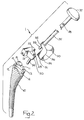
- Figs. 6-11 illustrate an alternate embodiment for adaptor 50 and planar reamer 30.
- the pivot mechanism between the adaptor 50 and planar reamer 30 includes a pivot pin 63 extending substantially perpendicularly from proximal adaptor surface 52 of adaptor 50.
- the supporting planar surface 32 of planar reamer 30 includes a corresponding pivot recess 43 for accepting pivot pin 63 of adaptor 50.
- the pivot recess 43 of planar reamer 30 includes a side opening 44 to allow the adaptor pivot pin 63 to pass through laterally into the pivot recess 43.
- the adaptor pivot pin 63 includes a post portion 65 with an enlarged circular head 64 thereon.
- the side opening 44 of pivot recess 43 extends into a slot 46 in a retaining platform 45.
- the side opening 44 also extends into an enlarged opening 47 above slot 46.
- the post portion 65 of pivot pin 63 can pass through the slot 46 in retaining platform 45, while the enlarged head 64 can pass through enlarged opening 47 above the retaining platform 45.
- the enlarged head 64 is larger than the slot 46 in the retaining platforn 45, so that enlarged head 64 can not drop through the slot 46.
- the adaptor pivot pin 63 is retained longitudinally in the pivot recess 43, and requires lateral sliding of the pivot pin 63 through side opening 44 for insertion of pivot pin 63 into pivot recess 43 and for removal of pivot pin 63 from pivot recess 43.
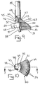
- the slot 46 may suitably be keyhole-shaped having a narrow passageway 48 and an enlarged rounded end 49 at an end of the narrow passageway 48 oppositely located from the side opening 44.
- the post portion 65 of pivot pin 63 has a substantially circular cross-section with two oppositely located flats 66 thereon, as shown in Fig. 11.
- the narrow passageway 48 enables the post portion 65 of pivot pin 63 to pass through in a nonpivotal or nonrotatable orientation with flats 66 aligned with the passageway 48.
- the enlarged rounded end 49 of slot 46 enables the post portion 65 to pivot therein when the post portion 65 is located in end 49 of slot 46.
- planar reamer 30 of the embodiments of Figs. 1-5 or 6-11 could mate directly with a base support (not shown) without an adaptor therebetween by modifying the proximal planar surface of the base support to be at the same relative angle as the supporting planar surface of the planar reamer and by modifying the pivot mechanism at the proximal planar surface to mate with the perpendicular pivot orientation of the planar reamer, as appropriate.
- such a surgical reamer assembly provides an adjustment of the level of planar cutting, but does not adjust the angle of planar cutting. If an adjustment of the angle of the planar cutting is desired or an adjustment of the angle and the level of planar cutting is desired, an adaptor would also be used as described herein.
- the components of the surgical reamer assembly may be made from any appropriate materials suitable for surgical instruments.
- a particularly advantageous material for surgical bone cutting tools is stainless steel, although the material is not limited thereto. Any suitable manufacturing processes may be utilized to manufacture the components.
Abstract
Description
- The present invention relates to a surgical reamer assembly. More specifically, the reamer assembly is used for cutting a planar bone surface.
- The use of planar reamers for reaming or cutting a flat, planar surface on bone is well known in the orthopaedic industry. One such type of planar reamer is used for reaming the calcar bone of a femur to match the undersurface of an extending collar on a collared femoral hip prosthesis. Such a planar reamer is shown in Fig. 7 of U.S. Patent 5,019,108 to Bertin et al. which shows a calcar reamer 40 with a pin 41 protruding from
cutting surface 43. The pin 41 fits directly intohole 35 of rasp 30 (of Fig. 6) functioning as a pivot. Thus, pivoting thesurface 43 about pin 41 planes the femoral bone to provide a flat bone contact to mate with the flat undersurface 18 of collar 17 of thehip implant 10. - Another such planar reamer is disclosed in U.S. 4,998,937 to Grimes. Fig. 9 shows a planar reamer 97 which fits directly over protruding pin 93 to ream a flat surface on the bone. Fig. 10 shows an alternate planing tool 99 with an integral post 103 depending therefrom which is inserted in an opening in
barrel 15 to cut a planar surface. - In the above references, the planar reaming surface either has a pivot post protruding directly therefrom for fitting in a hole on a supporting surface or the planar reaming surface has a hole therein for fitting directly over a protruding post.
- It is an object of the invention to provide a surgical reamer assembly for cutting a planar bone surface in which the angle or level of the cutting of the planar reamer is to be adjusted.
- It is a further object of the present invention to provide a surgical reamer assembly which cuts a planar surface at a level that is below the level of the mating pivoting surfaces.
- It is a still further object of the invention to provide an adaptor for positioning between the base support and the planar reamer.
- It is another object of the invention to provide such an adaptor which enables reaming a planar surface at an angle different from the angle of the proximal planar surface of the base support.
- The present invention provides a reamer assembly for cutting a planar bone surface. The surgical reamer assembly enables the angle or the level of the cutting of the planar reamer to be adjusted. This adjustment is advantageously provided by the use of an adaptor which is positioned between the base support on the planar reamer instrument.
- These features and objects of the invention, as well as others, will become apparent to those skilled in the art by referring to the accompanying drawings:
- Fig. 1 is a side elevational view illustrating the surgical reamer assembly of the present invention shown in use on a femur;
- Fig. 2 is an exploded perspective view of the surgical reamer assembly of Fig. 1 including the base support, the adaptor, and the planar reamer;
- Fig. 3 is bottom plan view with a partial cross-section, of the adaptor of Fig. 2;
- Fig. 4 is a rear elevation view of the adaptor of Fig. 2;
- Fig. 5 is a bottom plan view of the planar reamer of Fig. 2;
- Fig. 6 is a side elevational view of an alternate embodiment for the adaptor and planar reamer of the present invention;
- Fig. 7 is a partial cross-sectional view of the planar reamer of Fig. 6 with the cross-section taken along lines 7-7 of Fig. 10;
- Fig. 8 is a side elevational view of the adaptor of Fig. 6;
- Fig. 9 is a side elevational view with the adaptor of Fig. 8 shown positioned in the planar reamer of Fig. 7 with the planar reamer shown in partial cross-section as in Fig. 7;
- Fig. 10 is a bottom plan view of the planar reamer of Fig. 6; and
- Fig. 11 is a cross-sectional view of the post portion of the pivot pin of
adaptor 50, with the cross-section taken along lines 11-11 of Fig. 8. - Figs. 1-5 illustrate a particularly advantageous embodiment of the surgical reamer assembly of the present invention, while Figs. 6-11 illustrate an alternate advantageous embodiment of the invention. The invention will be described with reference to a surgical reamer assembly for planing a flat bone surface for mating with the flat undersurface of an extending collar on a collared femoral hip prosthesis. However, it is understood that the principles of the invention are applicable to a surgical reamer assembly for planing any suitable flat bone surface.
- The embodiment of Figs. 1-5 illustrate
surgical reamer assembly 1. Theassembly 1 includes abase support 10, aplanar reamer 30, and anadaptor 50 for positioning betweensupport 10 and reamer 30. - The base support 10, as shown, may be a rasp cutter for forming a cavity 8 in the
femoral bone 7, as shown in Fig. 1. Thebase support 10 in Fig. 1 is shown positioned in thefemur 7. It is desired to cut or ream thefemoral bone 7 to provide a flat planar bone surface 9 for mating with the flat undersurface of a collar on a corresponding collared femoral hip prosthesis (not shown). - The
base support 10 has a proximal planar surface 11 which is oriented at a first angle 3 to reference axis A. Reference axis A, as shown, may suitably be the main axis of theelongated base support 10. The first angle 3 of proximal planar surface 11 may be designed and oriented to mate with other mating instrumentation (not shown), such as a releasable rasp handle and/or a cone or neck provisional for use during the surgical procedure. U.S. Patent 4,921,493 to Webb, Jr. et al. shows an example of a releasable rasp handle, while U.S. Patent 4,963,155 to Lazzeri et al. shows an example of cone or neck provisional, with a rasp cutter. Both of these patents are incorporated herein by reference. - The
planar reamer 30 has acutting surface 31 oriented at asecond angle 5 to reference axisA. Cutting surface 31 will be used to cut corresponding flat planar bone surface 9 which will then be parallel to cuttingsurface 31. Thesecond angle 5 is different from the first angle 3. The first angle may suitably be about 60 degrees to the reference axis, while the second angle may suitably be about 45 degrees to the reference axis. Theplanar reamer 30 also has a supportingplanar surface 32 also oriented atsecond angle 5. - The
adaptor 50 has adistal adaptor surface 51 oriented at first angle 3 for mating with and connecting to the proximal planar surface 11 ofbase support 10. Theadaptor 50 also includes aproximal adaptor surface 52 oriented atsecond angle 5 for mating with the supportingplanar surface 32 ofplanar reamer 30. Theproximal adaptor surface 52 and the mating supportingplanar surface 32 include a pivot mechanism therebetween to allow pivoting of theplanar reamer 30 about the pivot mechanism to provide planar reaming withcutting surface 31. - The pivot mechanism includes a
pivot pin 33 extending substantially perpendicularly from the supportingplanar surface 32 ofplanar reamer 30, and theproximal adaptor surface 52 includes apivot recess 53 for accepting thepivot pin 33 ofplanar reamer 30. - The
planar reamer 30 includes anelongated handle 35 extending therefrom.Handle 35 may include an enlargedproximal knob 37 thereon. In addition, throughholes 38 may be provided inhandle 35 to accept a cross rod (not shown) therethrough. Such cross rods are known for use with planar reamers. - The
cutting surface 31 depends from the supportingplanar surface 32, and is connected to the supportingplanar surface 32 by a connectingportion 36, such that thecutting surface 31 is parallel to, but non-coplanar with the supportingplanar surface 32. Thecutting surface 31 is lower than the proximal planar surface 11 ofbase support 10 when thereamer 30,adaptor 50 andbase support 10 are assembled together. The connectingportion 36 is laterally spaced frompivot pin 33 to provide sufficient clearance for pivoting aboutadaptor 50 andbase support 10. Thecutting surface 31 ofplanar reamer 30 includes cuttingteeth 34 thereon. - The
base support 10 includes an extendingledge surface 12 about thebase support 10 which is spaced below the proximal planar surface 11. Theledge surface 12 is separated from the proximal planar surface 11 by a raisedwall 16. Theledge surface 12 is oriented atsecond angle 5. The cuttingsurface 31 ofplanar reamer 30 is substantially coplanar withledge surface 12 when thebase support 10,adaptor 50, andplanar reamer 30 are assembled together, as shown in Fig. 1, to provide planar cutting via cuttingsurface 31 oriented at thesecond angle 5. - The
adaptor 50 and thebase support 10 are releasably assembled together, so that theadaptor 50 does not rotate relative to thebase support 10. The proximal planar surface 11 ofbase support 10 includes a locatingrecess 13 for accepting the corresponding locatingpin 54 which extends from the distal adaptor surface. In order to prevent rotation of the locatingpin 54 in locatingrecess 13, a raisedspline 14 may be provided which extends from proximal planar surface 11. Thespline 14 is spaced from locatingrecess 13. Accordingly, thedistal adaptor surface 51 includes acorresponding spline receptacle 55 for receivingspline 14 ofbase support 10. The spaced interconnections ofpin 54 withrecess 13 and ofspline 14 withspline receptacle 55 prevents rotation between theadaptor 50 andbase support 10. - In order to releasably secure the
adaptor 50 onbase support 10, thespline 14 may be provided with agroove 15 for accepting biased ball plungers 56. Two oppositely locatedball plungers 56 may be provided as shown in Fig. 3. The ball plungers 56 are biased to extend fromadaptor 50 intospline receptacle 55, and thus intogroove 15 ofspline 14 whenadaptor 50 is assembled tobase support 10 to releasably retainadaptor 50 onbase support 10. Thebiased ball plungers 56 are each biased by a connectingspring 57, such that theball plungers 56 compress and recede into the adaptor as theball plungers 56 pass overspline 14 upon the application of connection force to connect theadaptor 50 tobase support 10 or upon application of separation force to removeadaptor 50 frombase support 10. Thespring 57 connected to each ball plunger is secured to a threadedstud 58 which is positioned in a threadedhole 59 inadaptor 50. - Figs. 6-11 illustrate an alternate embodiment for
adaptor 50 andplanar reamer 30. In this alternate embodiment, the pivot mechanism between theadaptor 50 andplanar reamer 30 includes apivot pin 63 extending substantially perpendicularly fromproximal adaptor surface 52 ofadaptor 50. The supportingplanar surface 32 ofplanar reamer 30 includes acorresponding pivot recess 43 for acceptingpivot pin 63 ofadaptor 50. - The
pivot recess 43 ofplanar reamer 30 includes aside opening 44 to allow theadaptor pivot pin 63 to pass through laterally into thepivot recess 43. Theadaptor pivot pin 63 includes apost portion 65 with an enlargedcircular head 64 thereon. Theside opening 44 ofpivot recess 43 extends into aslot 46 in a retainingplatform 45. Theside opening 44 also extends into anenlarged opening 47 aboveslot 46. Thus, thepost portion 65 ofpivot pin 63 can pass through theslot 46 in retainingplatform 45, while theenlarged head 64 can pass throughenlarged opening 47 above the retainingplatform 45. Theenlarged head 64 is larger than theslot 46 in the retainingplatforn 45, so thatenlarged head 64 can not drop through theslot 46. Thus, theadaptor pivot pin 63 is retained longitudinally in thepivot recess 43, and requires lateral sliding of thepivot pin 63 throughside opening 44 for insertion ofpivot pin 63 intopivot recess 43 and for removal ofpivot pin 63 frompivot recess 43. - The
slot 46 may suitably be keyhole-shaped having anarrow passageway 48 and an enlargedrounded end 49 at an end of thenarrow passageway 48 oppositely located from theside opening 44. Thepost portion 65 ofpivot pin 63 has a substantially circular cross-section with two oppositely locatedflats 66 thereon, as shown in Fig. 11. Thus, thenarrow passageway 48 enables thepost portion 65 ofpivot pin 63 to pass through in a nonpivotal or nonrotatable orientation withflats 66 aligned with thepassageway 48. The enlargedrounded end 49 ofslot 46 enables thepost portion 65 to pivot therein when thepost portion 65 is located inend 49 ofslot 46. - In accordance with the present invention, it is noted that the
planar reamer 30 of the embodiments of Figs. 1-5 or 6-11 could mate directly with a base support (not shown) without an adaptor therebetween by modifying the proximal planar surface of the base support to be at the same relative angle as the supporting planar surface of the planar reamer and by modifying the pivot mechanism at the proximal planar surface to mate with the perpendicular pivot orientation of the planar reamer, as appropriate. This would enable a planar surface to be cut by the depending cutting surface of the planar reamer at a level below the level of the mating pivoting surfaces of the proximal planar surface and mating supporting planar surface. It is noted that such a surgical reamer assembly provides an adjustment of the level of planar cutting, but does not adjust the angle of planar cutting. If an adjustment of the angle of the planar cutting is desired or an adjustment of the angle and the level of planar cutting is desired, an adaptor would also be used as described herein. - It is noted that the components of the surgical reamer assembly may be made from any appropriate materials suitable for surgical instruments. A particularly advantageous material for surgical bone cutting tools is stainless steel, although the material is not limited thereto. Any suitable manufacturing processes may be utilized to manufacture the components.
- While this invention has been described in terms of particular advantageous embodiments, those skilled in the art can appreciate that modifications can be made without departing from the spirit and scope of this invention.
Claims (28)
- A surgical reamer assembly for planing a bone surface comprising: a) a base support having a reference axis and a proximal planar surface oriented at a first angle to said reference axis; b) a planar reamer having a cutting surface oriented at a second angle to said reference axis, said second angle being different from said first angle, and a supporting planar surface connected to the cutting surface and also oriented at said second angle, and c) an adaptor for positioning between the base support and the planar reamer, the adaptor having a distal adaptor surface, oriented at said first angle for mating with and connecting to the proximal planar surface of the base support, and a proximal adaptor surface orientated at said second angle for mating with the supporting planar surface of the planar reamer, wherein the proximal adaptor surface and the mating supporting planar surface include a pivot means therebetween, thereby allowing pivoting of the planar reamer about said pivot means to provide planar reaming with said cutting surface.
- The assembly of Claim 1 wherein the pivot means includes a pivot pin extending substantially perpendicularly from the supporting planar surface of the planar reamer and the proximal adaptor surface includes a pivot recess for accepting the pivot pin of the planar reamer.
- The assembly of Claim 1 wherein the pivot means includes a pivot pin extending substantially perpendicularly from the proximal adaptor surface of the adaptor and the supporting planar surface of the planar reamer includes a pivot recess for accepting the pivot pin of the adaptor.
- The assembly of Claim 1 wherein the pivot means includes a pivot pin extending perpendicularly from one of either the supporting planar surface of the planar reamer or from the proximal adaptor surface of the adaptor, and wherein the other of said two surfaces includes a pivot recess for accepting the pivot pin.
- The assembly of Claim 1 wherein the cutting surface includes cutting teeth thereon.
- The assembly of Claim 1 wherein the planar reamer includes an elongated handle extending therefrom.
- The assembly of Claim 1 wherein the cutting surface depends from the supporting planar surface and is connected to the supporting planar surface by a connecting portion, such that the cutting surface is parallel to, but non-coplanar with the supporting planar surface.
- The assembly of Claim 7 wherein the base support includes an extending ledge surface about the base support spaced below said proximal planar surface, said ledge surface being oriented at said second angle, and wherein said cutting surface of the planar reamer is substantially coplanar with said ledge surface when the base support, adaptor, and planar reamer are assembled together.
- The assembly of Claim 7 wherein the connecting portion is laterally spaced from the pivot pin.
- The assembly of Claim 1 wherein the first angle is about 60 degrees and the second angle is about 45 degrees.
- The assembly of Claim 1 wherein an anti-rotation means is further provided between the adaptor and the base support.
- The assembly of Claim 1 wherein the adaptor is releasably connected to the base support and wherein the proximal planar surface of the base support includes a locating recess therein, and the adaptor includes a corresponding locating pin extending from the distal adaptor surface.
- The assembly of Claim 12 wherein an anti-rotation means is further provided between the adaptor and the base support.
- The assembly of Claim 13 wherein the anti-rotation means includes a raised spline extending from the proximal planar surface, said spline spaced from the locating recess, and wherein the distal adaptor surface includes a corresponding spline receptacle for receiving the spline.
- The assembly of Claim 14 wherein the spline includes a groove and the adaptor includes a ball plunger means which is biased to extend from the adaptor into the spline receptacle and into the groove of the spline when the adaptor is assembled to the base support to releasably retain the adaptor onto the base support.
- The assembly of Claim 15 wherein the ball plunger means is spring biased such that the ball plunger means compresses and recedes into the adaptor as the ball plunger means passes over the spline upon the application of connection force to connect the adaptor to the base support or upon application of separation force to remove the adaptor from the base support.
- The assembly of Claim 3 wherein the pivot recess in the planar reamer includes a side opening to allow the adaptor pivot pin to pass through laterally into the pivot recess.
- The assembly of Claim 17 wherein the adaptor pivot pin includes a post portion with an enlarged head on the post portion, and wherein the side opening of the pivot recess in the planar reamer extends into a slot in a retaining platform with an enlarged opening above the slot, such that the post portion of the adaptor pivot pin can pass through the slot in the retaining platform and the enlarged head can pass through the enlarged opening above the retaining platform, and wherein the enlarged head is larger than the slot in the retaining platform so that the enlarged head can not drop through the slot, thereby retaining the adaptor pivot pin longitudinally in the pivot recess of the planar reamer, and requiring lateral sliding of the pivot pin through the side opening for insertion into and removal from the pivot recess.
- The assembly of Claim 18 wherein the slot is a keyhole shaped slot having a narrow passageway and an enlarged rounded end at an end of the narrow passageway oppositely located from the side opening, and wherein the post portion of the pivot pin has a substantially circular cross-section with two oppositely located flats thereon, so that said passageway enables the post portion of the pivot pin to pass through in a nonpivotal or nonrotatable orientation with the flats of the post portion aligned with the passageway and so that said enlarged rounded end of the slot enables the post portion to pivot therein.
- The assembly of Claim 4 wherein the pivot recess includes a side opening to allow the pivot post to pass through laterally into the pivot recess.
- The assembly of Claim 20 wherein the pivot pin includes a post portion with an enlarged head on the post and wherein the side opening of the pivot recess opens into a slot in a retaining platform with an enlarged opening adjacent the slot, such that the post portion of the pivot pin can pass through the slot in the retaining platform and the enlarged head can pass through the enlarged opening adjacent the retaining platform, and wherein the enlarged head is larger than the slot in the retaining platform so that the enlarged head can not pass longitudinally through the slot, thereby retaining the pivot pin longitudinally in the pivot recess, and requiring lateral sliding of the pivot pin through the side opening for insertion into and removal from the pivot recess.
- A surgical reamer assembly for planing a bone surface comprising: a) a base support having a reference axis and a proximal planar surface oriented at a first angle to said reference axis; b) a planar reamer having a cutting surface oriented at a second angle to said reference axis, said second angle being different from said first angler and a supporting planar surface connected to the cutting surface and also oriented at said second angle, said supporting planar surface including a pivot pin extending substantially perpendicularly therefrom; and c) an adaptor for positioning between the base support and the planar reamer, the adaptor having a distal adaptor surface, oriented at said first angle for mating with and connecting to the proximal planar surface of the base support, and a proximal adaptor surface orientated at said second angle for mating with the supporting planar surface of the planar reamer, wherein the proximal adaptor surface includes a pivot recess for accepting the pivot pin of the planar reamer, thereby allowing pivoting of the planar reamer about said pivot pin to provide planar reaming with said cutting surface.
- The assembly of Claim 7 wherein the cutting surface of the planar reamer is lower than the proximal planar surface of the base support when the reamer, the adaptor, and the base support are assembled together.
- A surgical reamer assembly for planing a bone surface comprising: a) a base support having a proximal planar surface; b) a planar reamer having a cutting surface connected to a supporting planar surface; and c) an adaptor for positioning between the base support and the planar reamer, the adaptor having a distal adaptor surface for mating with and connecting to the proximal planar surface of the base support, and a proximal adaptor surface for mating with the supporting planar surface of the planar reamer, wherein the proximal adaptor surface and the mating supporting planar surface include a pivot means therebetween, thereby allowing pivoting of the planar reamer about said pivot means to provide planar reaming with said cutting surface, and wherein the cutting surface depends from the supporting planar surface and is connected to the supporting planar surface by a connecting portion such that the cutting surface is lower than the proximal planar surface of the base support, when the reamer, the adaptor, and the base support are assembled together.
- A surgical reamer assembly for planing a bone surface comprising: a) a base support having a proximal planar surface; and b) a planar reamer having a cutting surface connected to a supporting planar surface, said supporting planar surface adapted to mate with the proximal planar surface of the base support, and wherein the proximal planar surface and the mating supporting planar surface include a pivot means therebetween, thereby allowing pivoting of the planar reamer about said pivot means to provide planar reaming with said cutting surface, and wherein the cutting surface depends from the supporting planar surface and is connected to the supporting planar surface by a connecting portion, such that the cutting surface is lower than the proximal planar surface of the base support, when the reamer is operatively assembled thereto.
- A surgical reamer assembly for cutting a planar bone surface, the assembly including a base support, a planar reamer, and an adaptor for positioning between the base support and the planar reamer, wherein the adaptor enables the angle or the level of the cutting of the planar reamer to be adjusted.
- The assembly of Claim 8 wherein the base support includes a raised wall which separates the extending ledge surface from the proximal planar surface.
- The assembly of Claim 26 wherein the base support includes a proximal planar surface and wherein the angle or the level of the cutting of the planar reamer is not coplanar with the proximal planar surface.
Applications Claiming Priority (2)
| Application Number | Priority Date | Filing Date | Title |
|---|---|---|---|
| US811101 | 1991-12-20 | ||
| US07/811,101 US5169401A (en) | 1991-12-20 | 1991-12-20 | Surgical reamer assembly |
Publications (3)
| Publication Number | Publication Date |
|---|---|
| EP0548485A2 true EP0548485A2 (en) | 1993-06-30 |
| EP0548485A3 EP0548485A3 (en) | 1994-05-25 |
| EP0548485B1 EP0548485B1 (en) | 1996-09-04 |
Family
ID=25205559
Family Applications (1)
| Application Number | Title | Priority Date | Filing Date |
|---|---|---|---|
| EP92117695A Expired - Lifetime EP0548485B1 (en) | 1991-12-20 | 1992-10-16 | Surgical reamer assembly |
Country Status (6)
| Country | Link |
|---|---|
| US (1) | US5169401A (en) |
| EP (1) | EP0548485B1 (en) |
| JP (1) | JP3677052B2 (en) |
| AU (1) | AU660724B2 (en) |
| CA (1) | CA2082098C (en) |
| DE (1) | DE69213422T2 (en) |
Cited By (3)
| Publication number | Priority date | Publication date | Assignee | Title |
|---|---|---|---|---|
| EP0788773A1 (en) * | 1996-02-08 | 1997-08-13 | Zimmer Limited | Tool to insert a prothesis |
| US8052687B2 (en) | 2006-09-29 | 2011-11-08 | Depuy Products, Inc. | Calcar planar |
| WO2019159061A3 (en) * | 2018-02-15 | 2019-10-17 | DePuy Synthes Products, Inc. | Orthopaedic surgical instrument system for preparing a patient's calcar |
Families Citing this family (50)
| Publication number | Priority date | Publication date | Assignee | Title |
|---|---|---|---|---|
| DE59300441D1 (en) * | 1992-04-01 | 1995-09-14 | Integral Medizintechnik | Bone rasp made of plastic. |
| EP0645992B1 (en) * | 1992-06-17 | 1998-03-04 | Minnesota Mining And Manufacturing Company | Instrumentation for preparing the femur for an artificial knee implant and for positioning the femoral component of the implant |
| US5951606A (en) * | 1992-11-20 | 1999-09-14 | Burke; Dennis W. | Centering device for femoral implant and method and apparatus for implementation thereof |
| JPH08508175A (en) * | 1992-11-20 | 1996-09-03 | バーク,デニス・ダブリュー | Femoral bone graft collar and placement device |
| US5403320A (en) * | 1993-01-07 | 1995-04-04 | Venus Corporation | Bone milling guide apparatus and method |
| US5961555A (en) | 1998-03-17 | 1999-10-05 | Huebner; Randall J. | Modular shoulder prosthesis |
| US5423822A (en) * | 1993-01-27 | 1995-06-13 | Biomet, Inc. | Method and apparatus for preparing a bone for receiving a prosthetic device |
| US5562673A (en) * | 1994-03-03 | 1996-10-08 | Howmedica Inc. | Awls for sizing bone canals |
| US5593451A (en) * | 1994-06-01 | 1997-01-14 | Implex Corp. | Prosthetic device and method of implantation |
| AU4138396A (en) * | 1994-12-05 | 1996-06-26 | Wright Medical Technology, Inc. | A modular humeral prosthesis, and modular instrumentation for preparing a humerus for same, and a method for implanting same |
| US5782835A (en) * | 1995-03-07 | 1998-07-21 | Innovasive Devices, Inc. | Apparatus and methods for articular cartilage defect repair |
| US5766261A (en) * | 1996-02-01 | 1998-06-16 | Osteonics Corp. | Femoral revision broach with modular trial components and method |
| US5711767A (en) * | 1996-07-11 | 1998-01-27 | Ciba Specialty Chemicals Corporation | Stabilizers for the prevention of gum formation in gasoline |
| US5755805A (en) * | 1996-07-25 | 1998-05-26 | Whiteside; Leo A. | Tapered prosthesis component |
| US5885295A (en) * | 1996-08-07 | 1999-03-23 | Biomet, Inc. | Apparatus and method for positioning an orthopedic implant |
| WO1998006359A1 (en) * | 1996-08-13 | 1998-02-19 | Grimes James B | Femoral head-neck prosthesis and method of implantation |
| US5810830A (en) * | 1996-11-13 | 1998-09-22 | Howmedica Inc. | Machining assembly and methods for preparing the medullary cavity of a femur in hip arthroplasty |
| US5993455A (en) * | 1996-11-13 | 1999-11-30 | Noble; Philip C. | Surgical broach and methods for preparing the medullary cavity of a femur in hip arthroplasty |
| US6494913B1 (en) | 1998-03-17 | 2002-12-17 | Acumed, Inc. | Shoulder prosthesis |
| US6165177A (en) * | 1998-12-24 | 2000-12-26 | Depuy Orthopaedics, Inc. | Alignment guide for insertion of stem prosthesis |
| US6120507A (en) * | 1999-01-29 | 2000-09-19 | Bristol-Myers Squibb Company | Instrument and method for seating prosthesis |
| US6224605B1 (en) * | 1999-11-24 | 2001-05-01 | Bristol-Myers Squibb Co. | Orthopaedic instrumentation assembly and method of using same |
| US8535382B2 (en) | 2000-04-10 | 2013-09-17 | Biomet Manufacturing, Llc | Modular radial head prostheses |
| US8114163B2 (en) | 2000-04-10 | 2012-02-14 | Biomet Manufacturing Corp. | Method and apparatus for adjusting height and angle for a radial head |
| US8920509B2 (en) | 2000-04-10 | 2014-12-30 | Biomet Manufacturing, Llc | Modular radial head prosthesis |
| US6783553B2 (en) | 2001-10-24 | 2004-08-31 | James B. Grimes | Prosthesis |
| US7217271B2 (en) * | 2002-09-13 | 2007-05-15 | Symmetry Medical, Inc. | Orthopaedic reamer driver for minimally invasive surgery |
| US6932821B2 (en) * | 2002-09-28 | 2005-08-23 | Precimed S.A. | Femoral broach with undercut teeth |
| US7835030B2 (en) * | 2004-03-26 | 2010-11-16 | Lexmark International, Inc. | Processing print jobs |
| US7588578B2 (en) | 2004-06-02 | 2009-09-15 | Facet Solutions, Inc | Surgical measurement systems and methods |
| US8597298B2 (en) | 2006-09-29 | 2013-12-03 | DePuy Synthes Products, LLC | Proximal reamer |
| US7537618B2 (en) | 2006-11-13 | 2009-05-26 | Howmedica Osteonics Corp. | Modular humeral head |
| US7857859B2 (en) * | 2007-06-13 | 2010-12-28 | Zimmer, Gmbh | Femur component for a hip joint prosthesis |
| FR2917282B1 (en) * | 2007-06-18 | 2009-08-14 | Euros Soc Par Actions Simplifi | TOOL ADAPTER FOR REALIZING FINAL EVIDENCE FOR SHOULDER PROSTHESIS |
| US8915922B2 (en) | 2007-09-13 | 2014-12-23 | Zsigmond Szanto | Method of planning and performing a spherical osteotomy using the 3-dimensional center of rotation of angulation (CORA) |
| EP2214571B1 (en) * | 2007-09-13 | 2016-01-06 | Zsigmond Szanto | Spherical osteotomy device |
| US8556912B2 (en) | 2007-10-30 | 2013-10-15 | DePuy Synthes Products, LLC | Taper disengagement tool |
| US8167882B2 (en) | 2008-09-30 | 2012-05-01 | Depuy Products, Inc. | Minimally invasive bone miller apparatus |
| US8506569B2 (en) | 2009-12-31 | 2013-08-13 | DePuy Synthes Products, LLC | Reciprocating rasps for use in an orthopaedic surgical procedure |
| US8556901B2 (en) * | 2009-12-31 | 2013-10-15 | DePuy Synthes Products, LLC | Reciprocating rasps for use in an orthopaedic surgical procedure |
| US8533921B2 (en) | 2010-06-15 | 2013-09-17 | DePuy Synthes Products, LLC | Spiral assembly tool |
| US9095452B2 (en) | 2010-09-01 | 2015-08-04 | DePuy Synthes Products, Inc. | Disassembly tool |
| US8486076B2 (en) | 2011-01-28 | 2013-07-16 | DePuy Synthes Products, LLC | Oscillating rasp for use in an orthopaedic surgical procedure |
| US9301765B2 (en) | 2011-12-16 | 2016-04-05 | Chow Ip, Llc | Prosthetic femoral stem for use in high offset hip replacement |
| US8992531B2 (en) | 2011-12-16 | 2015-03-31 | Chow Ip, Llc | Prosthetic femoral stem for use in high impact hip replacement |
| US9113918B2 (en) * | 2013-03-15 | 2015-08-25 | Depuy (Ireland) | Femoral surgical instrument and method of using same |
| JP6235331B2 (en) * | 2013-12-25 | 2017-11-22 | 京セラ株式会社 | Hip surgery instrument |
| JP6160659B2 (en) * | 2015-07-16 | 2017-07-12 | 京セラ株式会社 | Surgical instrument for hip replacement |
| WO2019117985A1 (en) * | 2017-12-15 | 2019-06-20 | Corex, Llc | Orthopedic adapter for an electric impacting tool |
| US20190247063A1 (en) * | 2018-02-15 | 2019-08-15 | DePuy Synthes Products, Inc. | Orthopaedic surgical instrument system and method for preparing a patient's calcar |
Citations (2)
| Publication number | Priority date | Publication date | Assignee | Title |
|---|---|---|---|---|
| US4187559A (en) * | 1975-04-04 | 1980-02-12 | Sybron Corporation | Body joint endoprosthesis |
| US5019108A (en) * | 1990-02-02 | 1991-05-28 | Bertin Kim C | Modular implant |
Family Cites Families (18)
| Publication number | Priority date | Publication date | Assignee | Title |
|---|---|---|---|---|
| US2785673A (en) * | 1952-05-06 | 1957-03-19 | Anderson Roger | Femoral prosthesis |
| CH552383A (en) * | 1972-04-06 | 1974-08-15 | Oscobal Ag | Femoral head prosthesis. |
| CH568753A5 (en) * | 1973-08-31 | 1975-11-14 | Oscobal Ag | |
| CH593674A5 (en) * | 1974-09-11 | 1977-12-15 | Friedrichsfeld Gmbh | |
| US4306550A (en) * | 1980-02-06 | 1981-12-22 | Minnesota Mining And Manufacturing Company | Combination including femoral rasp and calcar facing reamer |
| EP0069252B1 (en) * | 1981-06-30 | 1986-10-22 | Waldemar Link (GmbH & Co.) | Joint endoprosthesis |
| DE3301415A1 (en) * | 1983-01-18 | 1984-07-19 | Robert Bosch Gmbh, 7000 Stuttgart | Endoprosthesis |
| US4467801A (en) * | 1983-03-09 | 1984-08-28 | Wright Manufacturing Company | Method and apparatus for shaping a proximal tibial surface |
| CH662268A5 (en) * | 1984-03-06 | 1987-09-30 | Protek Ag | Hip joint prosthesis. |
| FR2569978B1 (en) * | 1984-09-10 | 1989-02-24 | Fournier Jacques Andre | IMPLANT FOR COXO-FEMORAL PROSTHESIS |
| US4601289A (en) * | 1985-04-02 | 1986-07-22 | Dow Corning Wright | Femoral trial prosthesis/rasp assembly |
| US4921493A (en) * | 1986-08-11 | 1990-05-01 | Zimmer, Inc. | Rasp tool |
| US4790852A (en) * | 1986-09-15 | 1988-12-13 | Joint Medical Products Corporation | Sleeves for affixing artificial joints to bone |
| US4795473A (en) * | 1987-01-09 | 1989-01-03 | Grimes James B | Extramedullary femoral head-neck prosthesis and method of implanting same |
| US4765328A (en) * | 1987-08-10 | 1988-08-23 | Osteonics Corp. | Surgical instrument handle coupling |
| US4963155A (en) * | 1989-08-30 | 1990-10-16 | Zimmer, Inc. | Attachment mechanism for modular surgical products |
| US5002581A (en) * | 1989-11-03 | 1991-03-26 | Dow Corning Wright Corporation | Modular hip joint prosthesis with adjustable anteversion |
| US5002578A (en) * | 1990-05-04 | 1991-03-26 | Venus Corporation | Modular hip stem prosthesis apparatus and method |
-
1991
- 1991-12-20 US US07/811,101 patent/US5169401A/en not_active Expired - Lifetime
-
1992
- 1992-10-16 DE DE69213422T patent/DE69213422T2/en not_active Expired - Fee Related
- 1992-10-16 AU AU27106/92A patent/AU660724B2/en not_active Ceased
- 1992-10-16 EP EP92117695A patent/EP0548485B1/en not_active Expired - Lifetime
- 1992-11-04 CA CA002082098A patent/CA2082098C/en not_active Expired - Fee Related
- 1992-11-09 JP JP29833892A patent/JP3677052B2/en not_active Expired - Fee Related
Patent Citations (2)
| Publication number | Priority date | Publication date | Assignee | Title |
|---|---|---|---|---|
| US4187559A (en) * | 1975-04-04 | 1980-02-12 | Sybron Corporation | Body joint endoprosthesis |
| US5019108A (en) * | 1990-02-02 | 1991-05-28 | Bertin Kim C | Modular implant |
Cited By (3)
| Publication number | Priority date | Publication date | Assignee | Title |
|---|---|---|---|---|
| EP0788773A1 (en) * | 1996-02-08 | 1997-08-13 | Zimmer Limited | Tool to insert a prothesis |
| US8052687B2 (en) | 2006-09-29 | 2011-11-08 | Depuy Products, Inc. | Calcar planar |
| WO2019159061A3 (en) * | 2018-02-15 | 2019-10-17 | DePuy Synthes Products, Inc. | Orthopaedic surgical instrument system for preparing a patient's calcar |
Also Published As
| Publication number | Publication date |
|---|---|
| AU2710692A (en) | 1993-06-24 |
| CA2082098A1 (en) | 1993-06-21 |
| JP3677052B2 (en) | 2005-07-27 |
| JPH05212069A (en) | 1993-08-24 |
| US5169401A (en) | 1992-12-08 |
| EP0548485A3 (en) | 1994-05-25 |
| CA2082098C (en) | 2004-03-09 |
| EP0548485B1 (en) | 1996-09-04 |
| DE69213422T2 (en) | 1997-01-23 |
| DE69213422D1 (en) | 1996-10-10 |
| AU660724B2 (en) | 1995-07-06 |
Similar Documents
| Publication | Publication Date | Title |
|---|---|---|
| EP0548485B1 (en) | Surgical reamer assembly | |
| US5658290A (en) | Assembly comprising reamer spindle and reamer for surgery | |
| US5628750A (en) | Tibial resection guide alignment apparatus and method | |
| CA1326987C (en) | Surgical instrument | |
| US5601563A (en) | Orthopaedic milling template with attachable cutting guide | |
| US4736737A (en) | Tibial cutting jig | |
| US4612922A (en) | Drilling apparatus and method | |
| US4473070A (en) | Intramedullary reamer | |
| US6045556A (en) | Broach for shaping a medullary cavity in a bone | |
| JP4675622B2 (en) | Minimally invasive bone comminution device | |
| AU736610B2 (en) | Machining assembly and methods for preparing the medullary cavity of a femur in hip arthroplasty | |
| US4601289A (en) | Femoral trial prosthesis/rasp assembly | |
| EP1240879B1 (en) | Hip implant assembly | |
| US5222955A (en) | Method for implanting a patellar prosthesis | |
| JP3097961B2 (en) | Equipment for preparing artificial prostheses | |
| AU645380B2 (en) | Surgical instrument | |
| EP0570500B1 (en) | Reamer | |
| US6277121B1 (en) | Patella reaming system | |
| EP0627903A1 (en) | Medical instrument and procedure | |
| US5431656A (en) | Intramedullary instrumentation to position means for preparing a tibial plateau with a posterior slope | |
| US5490853A (en) | Orthopedic bone plug cutter |
Legal Events
| Date | Code | Title | Description |
|---|---|---|---|
| PUAI | Public reference made under article 153(3) epc to a published international application that has entered the european phase |
Free format text: ORIGINAL CODE: 0009012 |
|
| AK | Designated contracting states |
Kind code of ref document: A2 Designated state(s): DE FR GB |
|
| PUAL | Search report despatched |
Free format text: ORIGINAL CODE: 0009013 |
|
| RHK1 | Main classification (correction) |
Ipc: A61B 17/16 |
|
| AK | Designated contracting states |
Kind code of ref document: A3 Designated state(s): DE FR GB |
|
| 17P | Request for examination filed |
Effective date: 19941107 |
|
| 17Q | First examination report despatched |
Effective date: 19950706 |
|
| GRAG | Despatch of communication of intention to grant |
Free format text: ORIGINAL CODE: EPIDOS AGRA |
|
| GRAH | Despatch of communication of intention to grant a patent |
Free format text: ORIGINAL CODE: EPIDOS IGRA |
|
| GRAH | Despatch of communication of intention to grant a patent |
Free format text: ORIGINAL CODE: EPIDOS IGRA |
|
| GRAA | (expected) grant |
Free format text: ORIGINAL CODE: 0009210 |
|
| AK | Designated contracting states |
Kind code of ref document: B1 Designated state(s): DE FR GB |
|
| REF | Corresponds to: |
Ref document number: 69213422 Country of ref document: DE Date of ref document: 19961010 |
|
| ET | Fr: translation filed | ||
| PLBE | No opposition filed within time limit |
Free format text: ORIGINAL CODE: 0009261 |
|
| STAA | Information on the status of an ep patent application or granted ep patent |
Free format text: STATUS: NO OPPOSITION FILED WITHIN TIME LIMIT |
|
| 26N | No opposition filed | ||
| REG | Reference to a national code |
Ref country code: GB Ref legal event code: IF02 |
|
| REG | Reference to a national code |
Ref country code: GB Ref legal event code: 732E |
|
| PGFP | Annual fee paid to national office [announced via postgrant information from national office to epo] |
Ref country code: DE Payment date: 20081201 Year of fee payment: 17 |
|
| PGFP | Annual fee paid to national office [announced via postgrant information from national office to epo] |
Ref country code: FR Payment date: 20081018 Year of fee payment: 17 |
|
| REG | Reference to a national code |
Ref country code: FR Ref legal event code: TP |
|
| PGFP | Annual fee paid to national office [announced via postgrant information from national office to epo] |
Ref country code: GB Payment date: 20081029 Year of fee payment: 17 |
|
| REG | Reference to a national code |
Ref country code: FR Ref legal event code: ST Effective date: 20100630 |
|
| PG25 | Lapsed in a contracting state [announced via postgrant information from national office to epo] |
Ref country code: FR Free format text: LAPSE BECAUSE OF NON-PAYMENT OF DUE FEES Effective date: 20091102 Ref country code: DE Free format text: LAPSE BECAUSE OF NON-PAYMENT OF DUE FEES Effective date: 20100501 |
|
| PG25 | Lapsed in a contracting state [announced via postgrant information from national office to epo] |
Ref country code: GB Free format text: LAPSE BECAUSE OF NON-PAYMENT OF DUE FEES Effective date: 20091016 |