EP0548048B1 - Shock wave treatment apparatus - Google Patents
Shock wave treatment apparatus Download PDFInfo
- Publication number
- EP0548048B1 EP0548048B1 EP93100734A EP93100734A EP0548048B1 EP 0548048 B1 EP0548048 B1 EP 0548048B1 EP 93100734 A EP93100734 A EP 93100734A EP 93100734 A EP93100734 A EP 93100734A EP 0548048 B1 EP0548048 B1 EP 0548048B1
- Authority
- EP
- European Patent Office
- Prior art keywords
- shock wave
- image
- ultrasonic wave
- doppler
- living body
- Prior art date
- Legal status (The legal status is an assumption and is not a legal conclusion. Google has not performed a legal analysis and makes no representation as to the accuracy of the status listed.)
- Expired - Lifetime
Links
Images


Classifications
-
- A—HUMAN NECESSITIES
- A61—MEDICAL OR VETERINARY SCIENCE; HYGIENE
- A61B—DIAGNOSIS; SURGERY; IDENTIFICATION
- A61B17/00—Surgical instruments, devices or methods, e.g. tourniquets
- A61B17/22—Implements for squeezing-off ulcers or the like on the inside of inner organs of the body; Implements for scraping-out cavities of body organs, e.g. bones; Calculus removers; Calculus smashing apparatus; Apparatus for removing obstructions in blood vessels, not otherwise provided for
- A61B17/225—Implements for squeezing-off ulcers or the like on the inside of inner organs of the body; Implements for scraping-out cavities of body organs, e.g. bones; Calculus removers; Calculus smashing apparatus; Apparatus for removing obstructions in blood vessels, not otherwise provided for for extracorporeal shock wave lithotripsy [ESWL], e.g. by using ultrasonic waves
- A61B17/2256—Implements for squeezing-off ulcers or the like on the inside of inner organs of the body; Implements for scraping-out cavities of body organs, e.g. bones; Calculus removers; Calculus smashing apparatus; Apparatus for removing obstructions in blood vessels, not otherwise provided for for extracorporeal shock wave lithotripsy [ESWL], e.g. by using ultrasonic waves with means for locating or checking the concrement, e.g. X-ray apparatus, imaging means
Definitions
- the present invention relates to shock wave treatment apparatuses according to the pre-characterizing parts of claims 1 and 6.
- WO 87/01927 discloses an apparatus comprising the features of these pre-characterizing parts. Echo waves of shock waves having reduced power are processed for displaying purposes.
- a shock wave generator 1 for destruction or disintegration of a concretion or the like within a living body, as disclosed in Japanese Patent Laid-Open Specification No. 62-49843.
- a shock wave transducer 2 having a spherical concave front surface of a certain curvature includes a central through hole 2a of a certain shape, and the transducer 2 is supported by a backing member 3 adhered to the back surface of the transducer 2.
- An ultrasonic wave probe 4 for scanning the living body to obtain a B-mode section image or the like is provided with an ultrasonic wave transmitting-receiving surface or array 4a in its one end, and the array 4a is located in the same spherical surface or a retracted position as or from the front surface of the transducer 2.
- the shock wave generator 1 is contacted to a living body 6 via a water bag 5 containing water therein.
- a concentration point positioning is required. That is, the concentration point of the shock waves generated by the transducer 2 is adjusted to coincide with the concretion.
- This concentration point positioning is effected by displaying a B-mode section image of the living body and a target mark representing the concentration point of the shock waves on the display and by allowing the target mark to coincide with the concretion on the display.
- the target mark is geometrically determined depending on the ultrasonic wave generator 1.
- the target mark in the B-mode image is geometrically determined depending on the generator, and the actual concentration point of the shock waves generated by the transducer is often somewhat different or shifted from the target mark.
- the actual concentration point of the shock waves can not be confirmed.
- it is also difficult to confirm the results of the shock wave generation for instance, a disintegrated or not disintegrated state and the extent and appearance of the disintegration of the concretion.
- a shock wave treatment apparatus having the features of claim 1.
- a shock wave treatment apparatus having the features of claim 6.
- Fig. 2 a shock wave treatment apparatus.
- a shock wave generator 16 includes a shock wave transducer 16a having a spherical concave surface for generating shock waves therefrom and a water bag 16b having flexible bellows 16c for performing an effective transmission of the shock waves to a living body P, for instance, in order to disintegrate a concretion 31 of an object 32 such as a kidney.
- the shock wave transducer 16a is formed with a central hole therein.
- various devices such as a vibrator of a concave semisphere form, an electromagnetic induction type sound source composed of a combination of a spiral coil and a metal membrane arranged close thereto, and the like can be applied to the shock wave transducer 16a.
- An ultrasonic wave probe 17 having a ultrasonic wave transmitting-receiving surface or array 17a in its end is arranged in the central hole portion of the shock wave transducer 16a.
- the ultrasonic wave probe 17 transmits ultrasonic waves toward the living body P and receives an ultrasonic wave echo therefrom to effect a scanning of the living body P for obtaining a B-mode section image, a CFM (color flow mapping) image and an M-mode image.
- a timing controller 20 outputs a shock wave generation timing signal to a delay counter 19 and a pulser 21.
- the pulser 21 sends a drive signal to the shock wave transducer 16a in order to drive the same, and its driving timing is controlled by the shock wave generation timing signal fed from the timing controller 20.
- the delay counter 19 outputs a delayed pulse DP to an RPG (rate pulse generator) timing delayed by a certain period of time after the shock wave generation timing.
- the delay timing of the delayed pulse DP ouput by the delay counter 19 is controlled by a delay timing set 18.
- the RPG 10 generates a delayed frame pulse DFP to a transmit-receive controller 11 and a DSC (digital scan converter) 14 in synchronization with the delayed pulse DP output from the delay counter 19.
- the transmit-receive controller 11 controls the ultrasonic wave probe 17 to transmit or receive the ultrasonic wave to or from the living body P.
- the transmit-receive controller 11 comprises a transmitter and a receiver.
- the transmitter includes a transmission delay device for setting a certain delay time for the transmission of the delayed frame pulse and a pulser for generating a pulse for driving the array 17a of the ultrasonic wave probe 17 in synchronization with the delay time given by the transmission delay device.
- the receiver includes a preamplifier for amplifying a ultrasonic wave echo received by the ultrasonic wave probe 17, a receipt delay device for setting a certain delay time for the output of the amplified ultrasonic wave echo, and an adder for adding the delayed echoes.
- a B-mode processor 12 includes a detector for performing an amplitude detection of an output addition signal of the transmit-receive controller 11, and an A/D (analog-digital) converter for converting the amplitude detected signal to a digital detected signal to obtain a monochrome B-mode section image.
- the operated results of the B-mode processor 12 are sent to the DSC 14.
- a CFM (color flow mapping) processor 13 includes a phase detector for effecting a phase detection of the ultrasonic wave echo, an MTI (moving target indication) filter for removing a clatter component of the output signal of the phase detector, a self correlator for performing a self correlation of the output signal of the MTI to obtain an ultrasonic wave doppler alteration frequency, and a processor for operating an average speed and a power of a moving object according to the ultrasonic wave doppler alteration frequency to obtain a CFM (color flow mapping) image. That is, the CFM processor 13 performs the color flow mapping process to obtain a CFM image. The obtained result of the CFM processor 13 is fed to the DSC 14.
- the DSC 14 is provided with a frame memory (FM) 14a, in which the scan conversion between the sampling and display systems is carried out.
- the writing timing of the data into the FM 14a of the DSC 14 is determined by the delayed frame pulse DFP output from the RPG 10.
- the data of the B-mode section image and the CFM image is stored in the FM 14a of the DSC 14.
- the scan conversion result in the DSC 14 is fed to a color display 15. On the color display 15, the monochrome B-mode section image 15a and the CFM image 15b overlapped thereon are reproduced.
- a large pressure such as several 100 to 1000 bar is caused at the concentration point.
- the object 31 receives a large pressure and is moved in a direction F. Then, after the shock wave 33 passes through the object 31, the object 31 is pulled back by a negative pressure component the shock wave 33 trails in the reverse direction F' to the direction F, as shown in Fig. 4. Thus, the object 31 performs damped oscillation.
- the object 31 When the object 31 is not disintegrated by the shock wave 33, the object 31 performs damped oscillation while the object 31 retains its original form.
- the disintegrated pieces of the object are moved in all directions depending on their relative positions with respect to the concentration point of the shock wave and the surrounding conditions thereof.
- the behavior of the disintegrated pieces can be observed by transmitting an ultrasonic wave to a certain region containing the disintegrated pieces, obtaining frequency alteration information of the ultrasonic wave and analyzing the obtained frequency alteration information.
- An ultrasonic wave doppler alteration frequency of an ultrasonic wave is obtained from a received ultrasonic wave echo, and a CFM (color flow mapping) process is effected on the basis of the ultrasonic wave doppler alteration frequency.
- the result of the CFM process is overlapped on a B-mode section image on a display, and this is used as a monitory image during a shock wave treatment, as hereinafter described in detail.
- the ultrasonic wave probe 17 effects the transmission and receipt of the ultrasonic wave to and from the living body P by the transmit-receive controller 11, and the transmit-receive controller 11 obtains the ultrasonic wave echo.
- the B-mode processor 12 outputs the result of the B-mode process to the DSC 14, and the B-mode section image 15a of the living body P is formed in the FM 14a of the DSC 14. Then, the data of the B-mode section image 15a is read out of the FM 14a and is sent to the display 15 to display the B-mode section image 15a thereon.
- the shock wave transducer 16a When the shock wave transducer 16a is driven by sending the shock wave generation timing signal to the pulser 21, the shock wave transducer 16a generates the shock waves to concentrate on the concretion 31 of the object such as the kidney in the living body P.
- the ultrasonic wave doppler alteration frequency in the living body P is operated from the ultrasonic wave echo obtained by the transmit-receive controller 11, and the CFM process is carried out on the basis of the ultrasonic wave doppler alteration frequency.
- the resulted data of the CFM process is fed to the DSC 14, and the CFM image is formed in the FM 14a of the DSC 14.
- the CFM image is mixed with the monochrome B-mode section image, and the monochrome B-mode section image and the CFM image overlapped thereon are displayed on the display 15.
- the writing of the data of the B-mode section image and the CFM image into the FM memory 14a of the DSC 14 with respect to the shock wave generation operation is performed as follows.
- the delayed frame pulse DFP is fed from the RPG 10 to the DSC 14 at the timing delayed by the predetermined period of time after the timing of the shock wave generation.
- the DSC 14 is started to score the data into the FM 14a at the timing of input of the delayed frame pulse DFP, and, when one frame of the data is stored in the FM 14a, the storing of the data is stopped. This step is repeated every input of the delayed frame pulse DFP into the DSC 14 or every shock wave generation in the shock wave transducer 16a.
- the data writing timing by the delayed frame pulse DFP or the delayed pulse DP can be freely determined by the delay timing set 18, as described above.
- the reproducing and displaying of the still picture images such as the B-mode section image and the CFM image can be carried out at the best timing so that the best mode of the shock wave concentration positioning, the shock wave generation results and the disintegration state of the concretion or the like can be readily determined or adjusted and observed.
- the CFM image display is effected as follows.
- the doppler signal of the concretion is larger with respect to that of the other tissue, particularly, the surrounding tissue, and hence the position of the concretion can be readily confirmed in the CFM image 15b by generating relatively weak shock waves during the positioning of the concretion. Also, even when the strong shock waves are generated in order to disintegrate the concretion after the positioning of the concretion, the concretion is moved larger than the tissue because of the acoustic impedance difference, and hence the position of the concretion can be easily confirmed in the CFM image 15b.
- the tissue of the living body P when the strong shock waves are imparted to the tissue of the living body P, the tissue is deformed and moved, and this is appeared in the CFM image 15b. Hence, the concentration region or point of the actually generated shock waves can be easily confirmed in the CFM image 15b.
- the moving condition of the concretion against the shock waves is different, it is readily known whether the concretion is disintegrated or not.
- the sizes, moving directions and degree of dispersion of the disintegrated concretion pieces can be readily confirmed in the CFM image 15b by the extent of color mixture and the hue variation.
- the position of the object such as the concretion within the living body can be readily confirmed, and the position of the concentration point of the actual shock waves can be readily confirmed on the display.
- the positioning of the concentration point of the actual shock waves on the object can be readily performed.
- the shock wave generation results of the object and extent and state of the disintegrated pieces of the object can be readily confirmed on the display. Therefore, the time and accuracy of the positioning of the concretion and the positioning of the shock waves on the concretion can be largely improved, and ineffective operations and operator's burden can be largely reduced.
- Fig. 6 there is shown a further shock wave treatment apparatus having a structure similar to that shown in Fig. 2, except an M-mode processor 22 for obtaining an M-mode image is also included.
- a first clock pulse generator 20a outputs a first clock pulse CP1 to a second clock pulse generator 20b.
- An RPG (rate pulse generator) 10 outputs a rate pulse as a frame pulse FP to a transmit-receive controller 11, a DSC (digital scan converter) 14 and the second clock pulse generator 20b.
- the second clock pulse generator 20b outputs a second clock pulse CP2 having the same interval as that of the first clock pulse CP1 as a shock wave generation timing signal to a delay counter 19 and a pulser 21 in synchronization with the frame pulse FP output from she RPG 10.
- the delay counter 19 outputs a freeze signal FS at a timing delayed by a certain period of time after the shock wave generation timing in synchronization with the frame pulse FP.
- the delay timing of the freeze signal FS output from the delay counter 19 is controlled to determine to integral number times as much as the interval of the frame pulse FP by a delay timing set 18.
- the M-mode processor 22 includes a detector for performing an amplitude detection of an output addition signal of the transmit-receive controller 11, and an A/D (analog-digital) converter for converting the amplitude detected signal to a digital detected signal to obtain a monochrome M-mode image.
- the operated results of the M-mode processor 22 are sent to the DSC 14.
- a CFM processor 13 performs the CFM process in both the B-mode and M-mode images.
- the CFM processor 13 can discriminate between the B-mode and M-mode image signals and mix or overlap the monochrome B-mode or M-mode image signals and the CFM signals to obtain the B-mode and M-mode images, as shown in Fig. 10.
- doppler signals are picked up from the ultrasonic wave echo and are processed with respect to only a certain direction such as, in practice, a shock wave concentration point direction d , as shown in Fig. 10a, in a depth of the living body P to obtain the M-mode image.
- a shock wave concentration point direction d as shown in Fig. 10a
- Fig. 10b One example of the M-mode image is shown in Fig. 10b.
- the M-mode image can be utilized.
- the doppler signals are processed over a certain area to display the CFM image on the display.
- the reproduceable number of the frame images per second is approximately 10, which may be somewhat varied depending on the various conditions.
- the doppler signals are operated only along one direction such as, in practice, the direction the shock wave concentration point is positioned, and thus much more frame images can be reproduced compared with that of the CFM imaging, that is, the resolving power in unit time can be largely improved, resulting in that the doppler signals can be observed with a high resolving power in the M-mode image.
- the writing of the data obtained in the B-mode processor 12, the CFM processor 13 and the M-mode processor 22 into the frame memory 14a of the DSC 14 with respect to the timing of the shock wave generation operation is carried out at the desired timing by using the freeze signal FS output from the delay counter 19 in a similar manner to the apparatus of Fig. 2 described above.
- the reproducing and displaying of the still picture images can be carried out at the best timing so that the best mode of the shock wave concentration positioning, the shock wave generation results and the disintegration state of the concretion or the like can be readily determined or adjusted and observed.
- Fig. 8 there is shown a further shock wave treatment apparatus having a similar structure to the above described ones.
- a timing controller 20 outputs a clock pulse CP as a shock wave generation timing signal to a delay counter 19 and a pulser 21.
- a delay counter 19 outputs a delayed clock pulse DCP to an RPG 10 at a timing delayed by a certain period of time after a shock wave generation timing.
- the delay timing of the delayed clock pulse DCP output by the delay counter 19 is continuously controlled by a delay timing set 18.
- a timing of a delayed frame pulse DFP is controlled by the delayed clock pulse DCP fed from the delay counter 19 in order to compulsorily synchronize with the timing of the delayed clock pulse DCP.
- the clock pulse CP as the shock wave generation timing signal, the delayed clock pulse DCP and the delayed frame pulse DFP.
- the writing of the data obtained in the B-mode processor 12, the CFM processor 13 and the M-mode processor 22 into the frame memory 14a of the DSC 14 with respect to the timing of the shock wave generation operation is carried out at the desired timing by using the delayed frame pulse DFP output from the RPG 10 in a similar manner to the above described embodiments.
- the delay timing of the delayed clock pulse DCP can be continuously changed, and hence more accurate control can be performed as compared with the apparatus of Fig. 6.
- a shock wave treatment apparatus having a similar construction to the apparatus of Fig. 2 described above, except that a doppler processor 29 for outputting doppler information in an audio signal form is provided.
- a timing controller 20 outputs a timing control signal TCS as a shock wave generation timing signal to a pulser 21 and a switch 27 for performing an open-close control in synchronization with the timing control signal TCS.
- a clock pulse generator 26 generates a clock pulse to a frequency divider 24 which outputs a frequency divided signal FDS to the timing controller 20.
- An RPG (rate pulse generator) 10 generates a rate pulse as a frame pulse FP to a transmit-receive controller 11, a DSC (digital scan converter) 14 and a delay circuit 23. The delay circuit 23 sets back the frame pulse FP a certain period of time and sends a delayed frame pulse DFP to the timing controller 20.
- the timing controller 20 outputs the shock wave generation timing signal TCS to the pulser 21 at a timing delayed by a desired period of time t after the timing of the frame pulse FP.
- the reproducing and displaying of the still picture images can be effected at the best timing in the same manner as described above.
- Fig. 12 there are schematically shown the frame pulse FP, the delayed frame pulse DFP, the frequency divided signal FDS and the timing control signal TCS along with on and off modes of the switch 27.
- a system controller 25 controls the operation of the whole system of the shock wave treatment apparatus.
- the writing of the data obtained in the B-mode processor 12 into a frame memory (FM) 14a with respect to the shock wave generation timing is started by the frame pulse FP fed from the RPG, and, when one frame of the data is stored in the FM 14a, the data storing is stopped. This step is repeated.
- a doppler processor 29 includes a phase detector for effecting a phase detection of a ultrasonic wave echo sent from the transmit-receive controller 11, and a processor for setting a sample gate position.
- audio signals representing doppler information in the sample gate position is picked up from the ultrasonic wave echo.
- the audio signals are fed from the doppler processor 29 to a speaker 28 via the switch 27, and the speaker 28 reproduces doppler sounds from the audio signals.
- the delay circuit 23 outputs the delayed frame pulse DFP to the timing controller 20, and the frequency divider 24 sends the frequency divided signal FDS to the timing controller 20.
- the timing controller 20 outputs the timing control signal TCS as the shock wave generation timing signal at the timing of the following delayed frame pulse DFP, i.e., in synchronization with the leading edge of the delayed frame pulse DFP.
- the shock wave transducer 16a is driven to generate the shock waves at the timing of the leading edge of the shock wave generation timing signal TCS.
- the affecting area direction or path of the shock waves can be positioned in a right hand side end portion 15c in the B-mode section image 15a, as shown in Fig. 11.
- the phase detection of the ultrasonic wave echo is effected and the doppler information is picked up in the form of the audio signals in the doppler processor 29.
- the audio signals are sent to the speaker 28 through the switch 27, and the speaker 28 reproduces the doppler sounds from the audio signals.
- the doppler information pickup is carried out by using the pulsed wave doppler method, and the doppler information in the sample gate position determined in the B-mode section image is obtained. That is, by setting the sample gate position to a portion containing the disintegrated object pieces in advance, the doppler information of or near the disintegrated object pieces can be effectively obtained.
- the continuous wave doppler method may be also applied.
- a particular vibrator for the continuous wave doppler information pickup may be provided near the ultrasonic wave probe 17.
- a part 17b of the vibrator elements of the array 17a of the ultrasonic wave probe 17 may be used for the continuous wave doppler information pickup only, as shown in Fig. 13.
- the switch 27 is turned off in synchronization with the shock wave generation timing signal output from the timing controller 20 to remove the shock wave components from the doppler sounds. That is, as shown in Fig. 12, the switch 27 is turned off at the timing of the leading edge of the timing control signal TCS fed from the timing controller 20 to prevent the shock wave components from mixing in the doppler sounds, with the result of clearly monitoring the doppler sounds. Further, by making the OFF period of time of the switch 27 to be variable, more accurate or precise control for removing the shock wave component can be performed.
- a CFM processor 13 and/or an M-mode processor 22 of Fig. 6 may be also provided in the apparatus described above, with the result of obtaining the same effects and advantages as those of the apparatuses of Figs. 2 and 6.
- a second embodiment of a shock wave treatment apparatus having the same structure as the first embodiment shown in Fig. 11, except a doppler phonocardiograph 30 is provided.
- the doppler phonocardiograph 30 includes a ultrasonic transmit-receive member 30a, a doppler phonocardiograph body 30b and a speaker 30c, which are coupled in series.
- the ultrasonic transmit-receive member 30a transmits an ultrasonic wave toward an object 31 such as a concretion within an internal organ such as a kidney 32 in a living body P and receives a reflected component.
- the body 30b picks up doppler information from the reflected component, and the doppler information is reproduced in the sound form by the speaker 30c.
- the body 30b and the speaker 30c may constitute first and second means, respectively.
- the body 30b includes a device for preventing shock wave components from mixing in the doppler sounds in synchronization with the shock wave generation timing signal output from the timing controller 20, this shock wave preventing device having a similar construction to that of the first embodiment shown in Fig. 11, with the result of clearly monitoring the doppler sounds.
- this shock wave preventing device having a similar construction to that of the first embodiment shown in Fig. 11, with the result of clearly monitoring the doppler sounds.
- the same effects and advantages as those of the first embodiment can be obtained.
Landscapes
- Health & Medical Sciences (AREA)
- Surgery (AREA)
- Nuclear Medicine, Radiotherapy & Molecular Imaging (AREA)
- Life Sciences & Earth Sciences (AREA)
- Biomedical Technology (AREA)
- Vascular Medicine (AREA)
- Orthopedic Medicine & Surgery (AREA)
- Engineering & Computer Science (AREA)
- Radiology & Medical Imaging (AREA)
- Heart & Thoracic Surgery (AREA)
- Medical Informatics (AREA)
- Molecular Biology (AREA)
- Animal Behavior & Ethology (AREA)
- General Health & Medical Sciences (AREA)
- Public Health (AREA)
- Veterinary Medicine (AREA)
- Ultra Sonic Daignosis Equipment (AREA)
Description
- The present invention relates to shock wave treatment apparatuses according to the pre-characterizing parts of
claims - In Fig. 1, there is shown a conventional
shock wave generator 1 for destruction or disintegration of a concretion or the like within a living body, as disclosed in Japanese Patent Laid-Open Specification No. 62-49843. In thisshock wave generator 1, ashock wave transducer 2 having a spherical concave front surface of a certain curvature includes a central throughhole 2a of a certain shape, and thetransducer 2 is supported by abacking member 3 adhered to the back surface of thetransducer 2. Anultrasonic wave probe 4 for scanning the living body to obtain a B-mode section image or the like is provided with an ultrasonic wave transmitting-receiving surface orarray 4a in its one end, and thearray 4a is located in the same spherical surface or a retracted position as or from the front surface of thetransducer 2. Theshock wave generator 1 is contacted to aliving body 6 via awater bag 5 containing water therein. - For instance, when a concretion within a living body is disintegrated using the above described
shock wave generator 1, a concentration point positioning is required. That is, the concentration point of the shock waves generated by thetransducer 2 is adjusted to coincide with the concretion. This concentration point positioning is effected by displaying a B-mode section image of the living body and a target mark representing the concentration point of the shock waves on the display and by allowing the target mark to coincide with the concretion on the display. In this case, the target mark is geometrically determined depending on theultrasonic wave generator 1. - However, in practice, it is not easy to confirm the position of the object such as the concretion or concretions to be disintegrated in the B-mode image on the display. The target mark in the B-mode image is geometrically determined depending on the generator, and the actual concentration point of the shock waves generated by the transducer is often somewhat different or shifted from the target mark. However, the actual concentration point of the shock waves can not be confirmed. Further, after the generation of the shock waves to the object such as the concretion, it is also difficult to confirm the results of the shock wave generation, for instance, a disintegrated or not disintegrated state and the extent and appearance of the disintegration of the concretion.
- It is therefore an object of the present invention to provide a shock wave treatment apparatus, free from the aforementioned defects and disadvantages of the prior art, which is capable of readily confirming a position of an object to be disintegrated and an actual concentration point of shock waves generated by a shock wave transducer, and confirming results of the shock wave generation to the object.
- In accordance with one aspect of the present invention, there is provided a shock wave treatment apparatus, having the features of
claim 1. - In accordance with another aspect of the present invention, there is provided a shock wave treatment apparatus, having the features of
claim 6. - The above and other objects, features and advantages of the present invention will more fully appear from the following description of the preferred embodiments with reference to the accompanying drawings, in which:
- Fig. 1 is a longitudinal cross sectional view of a conventional shock wave generator;
- Fig. 2 is a block diagram of a shock wave treatment apparatus disclosed in order to support the description of the embodiments of the invention;
- Figs. 3 to 5 are schematic views of an object to be disintegrated by giving shock waves generated by a transducer;
- Fig. 6 is a block diagram of a further shock wave treatment apparatus;
- Fig. 7 is a timing chart including pulses representing action timings in the apparatus shown in Fig. 6;
- Fig. 8 is a block diagram of a further shock wave treatment apparatus;
- Fig. 9 is a timing chart including pulses representing action timings in the apparatus shown in Fig. 8;
- Fig. 10 is a schematic view showing a B-mode section image and an M-mode image on a display obtained in the apparatuses shown in Figs. 6 and 8;
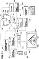
- Fig. 11 is a block diagram of a first embodiment of a shock wave treatment apparatus according to the present invention;
- Fig. 12 is a timing chart including pulses representing action timings in the apparatus shown in Fig. 11;
- Fig. 13 is a fragmentary block diagram of a further embodiment of a ultrasonic wave probe used in a shock wave treatment apparatus according to the present invention; and
- Fig. 14 is a block diagram of a second embodiment of a shock wave treatment apparatus according to the present invention.
- Referring now to the drawings, wherein like reference characters designate like or corresponding members throughout the several views and thus the repeated description thereof may be omitted for the brevity, there is shown in Fig. 2 a shock wave treatment apparatus.
- In Fig. 2, a
shock wave generator 16 includes ashock wave transducer 16a having a spherical concave surface for generating shock waves therefrom and awater bag 16b havingflexible bellows 16c for performing an effective transmission of the shock waves to a living body P, for instance, in order to disintegrate aconcretion 31 of anobject 32 such as a kidney. Theshock wave transducer 16a is formed with a central hole therein. In this embodiment, various devices such as a vibrator of a concave semisphere form, an electromagnetic induction type sound source composed of a combination of a spiral coil and a metal membrane arranged close thereto, and the like can be applied to theshock wave transducer 16a. Anultrasonic wave probe 17 having a ultrasonic wave transmitting-receiving surface orarray 17a in its end is arranged in the central hole portion of theshock wave transducer 16a. Theultrasonic wave probe 17 transmits ultrasonic waves toward the living body P and receives an ultrasonic wave echo therefrom to effect a scanning of the living body P for obtaining a B-mode section image, a CFM (color flow mapping) image and an M-mode image. - A
timing controller 20 outputs a shock wave generation timing signal to adelay counter 19 and apulser 21. Thepulser 21 sends a drive signal to theshock wave transducer 16a in order to drive the same, and its driving timing is controlled by the shock wave generation timing signal fed from thetiming controller 20. The delay counter 19 outputs a delayed pulse DP to an RPG (rate pulse generator) timing delayed by a certain period of time after the shock wave generation timing. The delay timing of the delayed pulse DP ouput by thedelay counter 19 is controlled by adelay timing set 18. - The
RPG 10 generates a delayed frame pulse DFP to a transmit-receivecontroller 11 and a DSC (digital scan converter) 14 in synchronization with the delayed pulse DP output from thedelay counter 19. The transmit-receivecontroller 11 controls theultrasonic wave probe 17 to transmit or receive the ultrasonic wave to or from the living body P. The transmit-receivecontroller 11 comprises a transmitter and a receiver. The transmitter includes a transmission delay device for setting a certain delay time for the transmission of the delayed frame pulse and a pulser for generating a pulse for driving thearray 17a of theultrasonic wave probe 17 in synchronization with the delay time given by the transmission delay device. The receiver includes a preamplifier for amplifying a ultrasonic wave echo received by theultrasonic wave probe 17, a receipt delay device for setting a certain delay time for the output of the amplified ultrasonic wave echo, and an adder for adding the delayed echoes. - A B-
mode processor 12 includes a detector for performing an amplitude detection of an output addition signal of the transmit-receivecontroller 11, and an A/D (analog-digital) converter for converting the amplitude detected signal to a digital detected signal to obtain a monochrome B-mode section image. The operated results of the B-mode processor 12 are sent to the DSC 14. A CFM (color flow mapping)processor 13 includes a phase detector for effecting a phase detection of the ultrasonic wave echo, an MTI (moving target indication) filter for removing a clatter component of the output signal of the phase detector, a self correlator for performing a self correlation of the output signal of the MTI to obtain an ultrasonic wave doppler alteration frequency, and a processor for operating an average speed and a power of a moving object according to the ultrasonic wave doppler alteration frequency to obtain a CFM (color flow mapping) image. That is, theCFM processor 13 performs the color flow mapping process to obtain a CFM image. The obtained result of theCFM processor 13 is fed to the DSC 14. - The DSC 14 is provided with a frame memory (FM) 14a, in which the scan conversion between the sampling and display systems is carried out. The writing timing of the data into the
FM 14a of the DSC 14 is determined by the delayed frame pulse DFP output from theRPG 10. The data of the B-mode section image and the CFM image is stored in theFM 14a of the DSC 14. The scan conversion result in the DSC 14 is fed to acolor display 15. On thecolor display 15, the monochrome B-mode section image 15a and theCFM image 15b overlapped thereon are reproduced. - When the shock waves are generated by the
shock wave transducer 16a, a large pressure such as several 100 to 1000 bar is caused at the concentration point. As shown in Fig. 3, soon after theshock wave 33 hits on anobject 31 such as a concretion to be disintegrated, theobject 31 receives a large pressure and is moved in a direction F. Then, after theshock wave 33 passes through theobject 31, theobject 31 is pulled back by a negative pressure component theshock wave 33 trails in the reverse direction F' to the direction F, as shown in Fig. 4. Thus, theobject 31 performs damped oscillation. - When the
object 31 is not disintegrated by theshock wave 33, theobject 31 performs damped oscillation while theobject 31 retains its original form. However, when the object is disintegrated by theshock wave 33, as shown in Fig. 5, the disintegrated pieces of the object are moved in all directions depending on their relative positions with respect to the concentration point of the shock wave and the surrounding conditions thereof. Hence, the behavior of the disintegrated pieces can be observed by transmitting an ultrasonic wave to a certain region containing the disintegrated pieces, obtaining frequency alteration information of the ultrasonic wave and analyzing the obtained frequency alteration information. - An ultrasonic wave doppler alteration frequency of an ultrasonic wave is obtained from a received ultrasonic wave echo, and a CFM (color flow mapping) process is effected on the basis of the ultrasonic wave doppler alteration frequency. The result of the CFM process is overlapped on a B-mode section image on a display, and this is used as a monitory image during a shock wave treatment, as hereinafter described in detail.
- The operation of the above described apparatus will now be described in detail.
- The
ultrasonic wave probe 17 effects the transmission and receipt of the ultrasonic wave to and from the living body P by the transmit-receivecontroller 11, and the transmit-receivecontroller 11 obtains the ultrasonic wave echo. The B-mode processor 12 outputs the result of the B-mode process to theDSC 14, and the B-mode section image 15a of the living body P is formed in theFM 14a of theDSC 14. Then, the data of the B-mode section image 15a is read out of theFM 14a and is sent to thedisplay 15 to display the B-mode section image 15a thereon. - When the
shock wave transducer 16a is driven by sending the shock wave generation timing signal to thepulser 21, theshock wave transducer 16a generates the shock waves to concentrate on theconcretion 31 of the object such as the kidney in the living body P. - In the
CFM processor 13, the ultrasonic wave doppler alteration frequency in the living body P is operated from the ultrasonic wave echo obtained by the transmit-receivecontroller 11, and the CFM process is carried out on the basis of the ultrasonic wave doppler alteration frequency. The resulted data of the CFM process is fed to theDSC 14, and the CFM image is formed in theFM 14a of theDSC 14. In theDSC 14, the CFM image is mixed with the monochrome B-mode section image, and the monochrome B-mode section image and the CFM image overlapped thereon are displayed on thedisplay 15. - The writing of the data of the B-mode section image and the CFM image into the
FM memory 14a of theDSC 14 with respect to the shock wave generation operation is performed as follows. - The delayed frame pulse DFP is fed from the
RPG 10 to theDSC 14 at the timing delayed by the predetermined period of time after the timing of the shock wave generation. TheDSC 14 is started to score the data into theFM 14a at the timing of input of the delayed frame pulse DFP, and, when one frame of the data is stored in theFM 14a, the storing of the data is stopped. This step is repeated every input of the delayed frame pulse DFP into theDSC 14 or every shock wave generation in theshock wave transducer 16a. The data writing timing by the delayed frame pulse DFP or the delayed pulse DP can be freely determined by the delay timing set 18, as described above. That is, in this embodiment, the reproducing and displaying of the still picture images such as the B-mode section image and the CFM image can be carried out at the best timing so that the best mode of the shock wave concentration positioning, the shock wave generation results and the disintegration state of the concretion or the like can be readily determined or adjusted and observed. - Then, the CFM image display is effected as follows.
- That is, different colors such as red and blue are applied to approaching and going away of the concretion and surrounding tissue thereof to or from the
ultrasonic wave probe 17, and the average speed or power of the moving concretion and surrounding tissue are exhibited by the brightness variation. Since the concretion and surrounding tissue thereof are different in acoustic impedance, the concretion is moved larger than the tissue, and it is easy to discriminate the moving concretion from the moving tissue in theCFM image 15b. - In this case, it is considered that the doppler signal of the concretion is larger with respect to that of the other tissue, particularly, the surrounding tissue, and hence the position of the concretion can be readily confirmed in the
CFM image 15b by generating relatively weak shock waves during the positioning of the concretion. Also, even when the strong shock waves are generated in order to disintegrate the concretion after the positioning of the concretion, the concretion is moved larger than the tissue because of the acoustic impedance difference, and hence the position of the concretion can be easily confirmed in theCFM image 15b. - Also, when the strong shock waves are imparted to the tissue of the living body P, the tissue is deformed and moved, and this is appeared in the
CFM image 15b. Hence, the concentration region or point of the actually generated shock waves can be easily confirmed in theCFM image 15b. - Further, since the moving condition of the concretion against the shock waves is different, it is readily known whether the concretion is disintegrated or not. When the concretion is disintegrated, the sizes, moving directions and degree of dispersion of the disintegrated concretion pieces can be readily confirmed in the
CFM image 15b by the extent of color mixture and the hue variation. - As described above, it is readily understood that by monitoring the B-mode section image and the CFM image overlapped thereon on the display during the shock wave treatment, the position of the object such as the concretion within the living body can be readily confirmed, and the position of the concentration point of the actual shock waves can be readily confirmed on the display. Hence, the positioning of the concentration point of the actual shock waves on the object can be readily performed. Also, the shock wave generation results of the object and extent and state of the disintegrated pieces of the object can be readily confirmed on the display. Therefore, the time and accuracy of the positioning of the concretion and the positioning of the shock waves on the concretion can be largely improved, and ineffective operations and operator's burden can be largely reduced.
- In Fig. 6, there is shown a further shock wave treatment apparatus having a structure similar to that shown in Fig. 2, except an M-
mode processor 22 for obtaining an M-mode image is also included. - A first
clock pulse generator 20a outputs a first clock pulse CP1 to a secondclock pulse generator 20b. An RPG (rate pulse generator) 10 outputs a rate pulse as a frame pulse FP to a transmit-receivecontroller 11, a DSC (digital scan converter) 14 and the secondclock pulse generator 20b. The secondclock pulse generator 20b outputs a second clock pulse CP2 having the same interval as that of the first clock pulse CP1 as a shock wave generation timing signal to adelay counter 19 and apulser 21 in synchronization with the frame pulse FP output from sheRPG 10. Thedelay counter 19 outputs a freeze signal FS at a timing delayed by a certain period of time after the shock wave generation timing in synchronization with the frame pulse FP. In Fig. 7, there are schematically shown the first clock pulse CP1, the frame pulse FP, the second clock pulse CP2 and the freeze signal FS. The delay timing of the freeze signal FS output from thedelay counter 19 is controlled to determine to integral number times as much as the interval of the frame pulse FP by a delay timing set 18. - The M-
mode processor 22 includes a detector for performing an amplitude detection of an output addition signal of the transmit-receivecontroller 11, and an A/D (analog-digital) converter for converting the amplitude detected signal to a digital detected signal to obtain a monochrome M-mode image. The operated results of the M-mode processor 22 are sent to theDSC 14. In this case, aCFM processor 13 performs the CFM process in both the B-mode and M-mode images. TheCFM processor 13 can discriminate between the B-mode and M-mode image signals and mix or overlap the monochrome B-mode or M-mode image signals and the CFM signals to obtain the B-mode and M-mode images, as shown in Fig. 10. - In the M-mode imaging process, doppler signals are picked up from the ultrasonic wave echo and are processed with respect to only a certain direction such as, in practice, a shock wave concentration point direction d, as shown in Fig. 10a, in a depth of the living body P to obtain the M-mode image. One example of the M-mode image is shown in Fig. 10b. In this embodiment, in addition to the B-mode section image and the CFM image, the M-mode image can be utilized.
- In case of the CFM imaging, the doppler signals are processed over a certain area to display the CFM image on the display. Hence, the reproduceable number of the frame images per second is approximately 10, which may be somewhat varied depending on the various conditions. In case of the M-mode imaging, the doppler signals are operated only along one direction such as, in practice, the direction the shock wave concentration point is positioned, and thus much more frame images can be reproduced compared with that of the CFM imaging, that is, the resolving power in unit time can be largely improved, resulting in that the doppler signals can be observed with a high resolving power in the M-mode image.
- The writing of the data obtained in the B-
mode processor 12, theCFM processor 13 and the M-mode processor 22 into theframe memory 14a of theDSC 14 with respect to the timing of the shock wave generation operation is carried out at the desired timing by using the freeze signal FS output from thedelay counter 19 in a similar manner to the apparatus of Fig. 2 described above. Hence, in this case, the reproducing and displaying of the still picture images can be carried out at the best timing so that the best mode of the shock wave concentration positioning, the shock wave generation results and the disintegration state of the concretion or the like can be readily determined or adjusted and observed. - In Fig. 8, there is shown a further shock wave treatment apparatus having a similar structure to the above described ones.
- A
timing controller 20 outputs a clock pulse CP as a shock wave generation timing signal to adelay counter 19 and apulser 21. Adelay counter 19 outputs a delayed clock pulse DCP to anRPG 10 at a timing delayed by a certain period of time after a shock wave generation timing. The delay timing of the delayed clock pulse DCP output by thedelay counter 19 is continuously controlled by a delay timing set 18. - In the
RPG 10, a timing of a delayed frame pulse DFP is controlled by the delayed clock pulse DCP fed from thedelay counter 19 in order to compulsorily synchronize with the timing of the delayed clock pulse DCP. In Fig. 9, there are schematically shown the clock pulse CP as the shock wave generation timing signal, the delayed clock pulse DCP and the delayed frame pulse DFP. In this embodiment, the writing of the data obtained in the B-mode processor 12, theCFM processor 13 and the M-mode processor 22 into theframe memory 14a of theDSC 14 with respect to the timing of the shock wave generation operation is carried out at the desired timing by using the delayed frame pulse DFP output from theRPG 10 in a similar manner to the above described embodiments. - The delay timing of the delayed clock pulse DCP can be continuously changed, and hence more accurate control can be performed as compared with the apparatus of Fig. 6.
- In Fig. 11, there is shown a first embodiment of a shock wave treatment apparatus according to the present invention, having a similar construction to the apparatus of Fig. 2 described above, except that a
doppler processor 29 for outputting doppler information in an audio signal form is provided. - A
timing controller 20 outputs a timing control signal TCS as a shock wave generation timing signal to apulser 21 and aswitch 27 for performing an open-close control in synchronization with the timing control signal TCS. Aclock pulse generator 26 generates a clock pulse to afrequency divider 24 which outputs a frequency divided signal FDS to thetiming controller 20. An RPG (rate pulse generator) 10 generates a rate pulse as a frame pulse FP to a transmit-receivecontroller 11, a DSC (digital scan converter) 14 and adelay circuit 23. Thedelay circuit 23 sets back the frame pulse FP a certain period of time and sends a delayed frame pulse DFP to thetiming controller 20. - The
timing controller 20 outputs the shock wave generation timing signal TCS to thepulser 21 at a timing delayed by a desired period of time t after the timing of the frame pulse FP. Hence, the reproducing and displaying of the still picture images can be effected at the best timing in the same manner as described above. In Fig. 12, there are schematically shown the frame pulse FP, the delayed frame pulse DFP, the frequency divided signal FDS and the timing control signal TCS along with on and off modes of theswitch 27. Asystem controller 25 controls the operation of the whole system of the shock wave treatment apparatus. - In the DSC, the writing of the data obtained in the B-
mode processor 12 into a frame memory (FM) 14a with respect to the shock wave generation timing is started by the frame pulse FP fed from the RPG, and, when one frame of the data is stored in theFM 14a, the data storing is stopped. This step is repeated. - A
doppler processor 29 includes a phase detector for effecting a phase detection of a ultrasonic wave echo sent from the transmit-receivecontroller 11, and a processor for setting a sample gate position. In thedoppler processor 29, audio signals representing doppler information in the sample gate position is picked up from the ultrasonic wave echo. The audio signals are fed from thedoppler processor 29 to aspeaker 28 via theswitch 27, and thespeaker 28 reproduces doppler sounds from the audio signals. - The operation of this apparatus will now be described in detail in connection with Figs. 11 and 12.
- The
delay circuit 23 outputs the delayed frame pulse DFP to thetiming controller 20, and thefrequency divider 24 sends the frequency divided signal FDS to thetiming controller 20. After the frequency divided signal FDS is turned to the high level, thetiming controller 20 outputs the timing control signal TCS as the shock wave generation timing signal at the timing of the following delayed frame pulse DFP, i.e., in synchronization with the leading edge of the delayed frame pulse DFP. Theshock wave transducer 16a is driven to generate the shock waves at the timing of the leading edge of the shock wave generation timing signal TCS. By using this timing control, the affecting area direction or path of the shock waves in a B-mode section image can be freely controlled. For instance, that is, although it is not effective or practical for treating an object such as a concretion, by varying the delay time of the frame pulse FP in thedelay circuit 23, the affecting area direction or path of the shock waves can be positioned in a right handside end portion 15c in the B-mode section image 15a, as shown in Fig. 11. - When the ultrasonic wave echo is sent from the transmit-receive
controller 11 to thedoppler processor 29, the phase detection of the ultrasonic wave echo is effected and the doppler information is picked up in the form of the audio signals in thedoppler processor 29. The audio signals are sent to thespeaker 28 through theswitch 27, and thespeaker 28 reproduces the doppler sounds from the audio signals. By monitoring the doppler sounds, the extent and state of the shock wave generation and disintegrated object pieces can be readily confirmed. - In this embodiment, the doppler information pickup is carried out by using the pulsed wave doppler method, and the doppler information in the sample gate position determined in the B-mode section image is obtained. That is, by setting the sample gate position to a portion containing the disintegrated object pieces in advance, the doppler information of or near the disintegrated object pieces can be effectively obtained.
- Further, in this embodiment, the continuous wave doppler method may be also applied. In this case, a particular vibrator for the continuous wave doppler information pickup may be provided near the
ultrasonic wave probe 17. Alternatively, apart 17b of the vibrator elements of thearray 17a of theultrasonic wave probe 17 may be used for the continuous wave doppler information pickup only, as shown in Fig. 13. - It is considered that, when the shock wave components are mixed with the doppler sounds to be output from the
speaker 28, it becomes difficult to monitor the doppler sounds. In order to prevent this problem, theswitch 27 is turned off in synchronization with the shock wave generation timing signal output from thetiming controller 20 to remove the shock wave components from the doppler sounds. That is, as shown in Fig. 12, theswitch 27 is turned off at the timing of the leading edge of the timing control signal TCS fed from thetiming controller 20 to prevent the shock wave components from mixing in the doppler sounds, with the result of clearly monitoring the doppler sounds. Further, by making the OFF period of time of theswitch 27 to be variable, more accurate or precise control for removing the shock wave component can be performed. - According to the present invention, a
CFM processor 13 and/or an M-mode processor 22 of Fig. 6 may be also provided in the apparatus described above, with the result of obtaining the same effects and advantages as those of the apparatuses of Figs. 2 and 6. - In Fig. 14, there is shown a second embodiment of a shock wave treatment apparatus according to the present invention, having the same structure as the first embodiment shown in Fig. 11, except a
doppler phonocardiograph 30 is provided. - In this case, the
doppler phonocardiograph 30 includes a ultrasonic transmit-receivemember 30a, adoppler phonocardiograph body 30b and aspeaker 30c, which are coupled in series. The ultrasonic transmit-receivemember 30a transmits an ultrasonic wave toward anobject 31 such as a concretion within an internal organ such as akidney 32 in a living body P and receives a reflected component. Thebody 30b picks up doppler information from the reflected component, and the doppler information is reproduced in the sound form by thespeaker 30c. Thebody 30b and thespeaker 30c may constitute first and second means, respectively. - In this embodiment, the
body 30b includes a device for preventing shock wave components from mixing in the doppler sounds in synchronization with the shock wave generation timing signal output from thetiming controller 20, this shock wave preventing device having a similar construction to that of the first embodiment shown in Fig. 11, with the result of clearly monitoring the doppler sounds. In this embodiment, the same effects and advantages as those of the first embodiment can be obtained.
Claims (7)
- A shock wave treatment apparatus, comprising:
means (16) for generating a shock wave and transmitting the shock wave toward a living body (P) having an object to be disintegrated by the shock wave (33);
an ultrasonic wave probe (17) for transmitting an ultrasonic wave toward the living body and for receiving an ultrasonic wave echo from the living body;
means (11, 12) for generating a B-mode section image of the living body on the basis of the wave echo,
means (15) for displaying the B-mode section image; and
means (29) for obtaining doppler information from the ultrasonic wave echo;
characterized by
means (14, 14a) for storing the B-mode image in synchronization with delay time means (23) at a certain period of time after the generation of the shock wave;
the means (29) for obtaining doppler information performing a phase detection of the ultrasonic wave echo; and by
means (28) for reproducing sound from the doppler information. - The apparatus of claim 1, further including means (13) for obtaining an ultrasonic wave doppler alteration frequency from the ultrasonic wave echo and for performing a color flow mapping process on the basis of the ultrasonic wave doppler alteration frequency to form a color flow mapping image of the living body, the displaying means (15) displaying the B-mode section image and the color flow mapping image.
- The apparatus of claim 2, further including means (22) for forming an M-mode image of the living body on the basis of the ultrasonic wave echo, the display means (15) displaying the B-mode section image and the color flow mapping image or the M-mode image and the color flow mapping image.
- The apparatus of any of claims 1 to 3, wherein the means for obtaining the doppler information utilize a pulsed wave doppler method.
- The apparatus of any of claims 1 to 3, wherein the doppler information is obtained by a continuous wave doppler method.
- A shock wave treatment apparatus, comprising:
means (16) for generating a shock wave and transmitting the shock wave toward a living body (P) having an object to be disintegrated by the shock wave (33);
an ultrasonic wave probe (17) for transmitting an ultrasonic wave toward the living body and for receiving an ultrasonic wave echo from the living body;
means (11, 12) for generating a B-mode section image of the living body on the basis of the wave echo,
means (15) for displaying the B-mode section image; and
means for obtaining doppler information;
characterized by
means (14, 14a) for storing the B-mode image in synchronization with delay time means (23) at a certain period of time after the generation of the shock wave; and
the means for obtaining doppler information includes a doppler phonocardiograph (30), which comprises means for transmitting and receiving ultrasound waves towards and from the object and means (30c) for reproducing sound from the doppler information. - The apparatus of any of claims 1 to 6, also including means (27) for preventing a shock wave component from being reproduced in a sound form.
Applications Claiming Priority (5)
| Application Number | Priority Date | Filing Date | Title |
|---|---|---|---|
| JP271456/88 | 1988-10-26 | ||
| JP63271456A JPH02116360A (en) | 1988-10-26 | 1988-10-26 | Impulse wave treating device |
| JP276627/88 | 1988-10-31 | ||
| JP63276627A JPH02121646A (en) | 1988-10-31 | 1988-10-31 | Shock wave treatment apparatus |
| EP89119924A EP0367116B1 (en) | 1988-10-26 | 1989-10-26 | Shock wave treatment apparatus |
Related Parent Applications (1)
| Application Number | Title | Priority Date | Filing Date |
|---|---|---|---|
| EP89119924.2 Division | 1989-10-26 |
Publications (2)
| Publication Number | Publication Date |
|---|---|
| EP0548048A1 EP0548048A1 (en) | 1993-06-23 |
| EP0548048B1 true EP0548048B1 (en) | 1996-02-14 |
Family
ID=26549721
Family Applications (2)
| Application Number | Title | Priority Date | Filing Date |
|---|---|---|---|
| EP93100734A Expired - Lifetime EP0548048B1 (en) | 1988-10-26 | 1989-10-26 | Shock wave treatment apparatus |
| EP89119924A Expired - Lifetime EP0367116B1 (en) | 1988-10-26 | 1989-10-26 | Shock wave treatment apparatus |
Family Applications After (1)
| Application Number | Title | Priority Date | Filing Date |
|---|---|---|---|
| EP89119924A Expired - Lifetime EP0367116B1 (en) | 1988-10-26 | 1989-10-26 | Shock wave treatment apparatus |
Country Status (3)
| Country | Link |
|---|---|
| US (1) | US5174294A (en) |
| EP (2) | EP0548048B1 (en) |
| DE (2) | DE68925702T2 (en) |
Cited By (4)
| Publication number | Priority date | Publication date | Assignee | Title |
|---|---|---|---|---|
| EP1374785A1 (en) | 2002-06-26 | 2004-01-02 | Dornier MedTech Systems GmbH | Lithotripter with a doppler ultrasound unit for hit/miss monitoring |
| DE10234144A1 (en) * | 2002-07-26 | 2004-02-05 | Dornier Medtech Gmbh | lithotripter |
| CN100353918C (en) * | 2004-01-28 | 2007-12-12 | 多恩尼尔医疗技术有限责任公司 | Stone crusher |
| US7988631B2 (en) | 2005-08-05 | 2011-08-02 | Dornier Medtech Systems Gmbh | Shock wave therapy device with image production |
Families Citing this family (26)
| Publication number | Priority date | Publication date | Assignee | Title |
|---|---|---|---|---|
| US5435311A (en) * | 1989-06-27 | 1995-07-25 | Hitachi, Ltd. | Ultrasound therapeutic system |
| DE4113697A1 (en) * | 1991-04-26 | 1992-11-05 | Dornier Medizintechnik | FOCAL AREA DEVICE FOR LITHOTRIPSY |
| DE4241161C2 (en) * | 1992-12-07 | 1995-04-13 | Siemens Ag | Acoustic therapy facility |
| JPH06209941A (en) * | 1993-01-18 | 1994-08-02 | Toshiba Corp | Ultrasonic diagnosing device |
| DE4302537C1 (en) * | 1993-01-29 | 1994-04-28 | Siemens Ag | Ultrasound imaging and therapy device - generates imaging waves and focussed treatment waves having two differing frequencies for location and treatment of e.g tumours |
| US5701898A (en) * | 1994-09-02 | 1997-12-30 | The United States Of America As Represented By The Department Of Health And Human Services | Method and system for Doppler ultrasound measurement of blood flow |
| DE4446192A1 (en) * | 1994-12-23 | 1996-07-04 | Wolf Gmbh Richard | Procedure for accurate hit control of treatment |
| WO1997003610A1 (en) * | 1995-07-21 | 1997-02-06 | Fraunhofer-Gesellschaft zur Förderung der angewandten Forschung e.V. | Device for the detection of concretions and cavitation bubbles |
| WO2005120373A1 (en) * | 2004-06-11 | 2005-12-22 | Hitachi Medical Corporation | Ultrasonic curing device |
| US8750983B2 (en) * | 2004-09-20 | 2014-06-10 | P Tech, Llc | Therapeutic system |
| US10219815B2 (en) | 2005-09-22 | 2019-03-05 | The Regents Of The University Of Michigan | Histotripsy for thrombolysis |
| US8057408B2 (en) | 2005-09-22 | 2011-11-15 | The Regents Of The University Of Michigan | Pulsed cavitational ultrasound therapy |
| US8535250B2 (en) * | 2006-10-13 | 2013-09-17 | University Of Washington Through Its Center For Commercialization | Method and apparatus to detect the fragmentation of kidney stones by measuring acoustic scatter |
| GB0624439D0 (en) * | 2006-12-07 | 2007-01-17 | Univ Warwick | Technique for treatment of gall-and kidney-stones |
| US9061131B2 (en) | 2009-08-17 | 2015-06-23 | Histosonics, Inc. | Disposable acoustic coupling medium container |
| US9901753B2 (en) | 2009-08-26 | 2018-02-27 | The Regents Of The University Of Michigan | Ultrasound lithotripsy and histotripsy for using controlled bubble cloud cavitation in fractionating urinary stones |
| WO2011028603A2 (en) | 2009-08-26 | 2011-03-10 | The Regents Of The University Of Michigan | Micromanipulator control arm for therapeutic and imaging ultrasound transducers |
| US9144694B2 (en) | 2011-08-10 | 2015-09-29 | The Regents Of The University Of Michigan | Lesion generation through bone using histotripsy therapy without aberration correction |
| WO2013166019A1 (en) | 2012-04-30 | 2013-11-07 | The Regents Of The University Of Michigan | Ultrasound transducer manufacturing using rapid-prototyping method |
| EP2903688A4 (en) | 2012-10-05 | 2016-06-15 | Univ Michigan | Bubble-induced color doppler feedback during histotripsy |
| ES2941665T3 (en) | 2013-07-03 | 2023-05-24 | Histosonics Inc | Optimized history excitation sequences for bubble cloud formation using shock scattering |
| US11432900B2 (en) | 2013-07-03 | 2022-09-06 | Histosonics, Inc. | Articulating arm limiter for cavitational ultrasound therapy system |
| WO2015027164A1 (en) | 2013-08-22 | 2015-02-26 | The Regents Of The University Of Michigan | Histotripsy using very short ultrasound pulses |
| ES2948135T3 (en) | 2015-06-24 | 2023-08-31 | Univ Michigan Regents | Histotripsy therapy systems for the treatment of brain tissue |
| US11813484B2 (en) | 2018-11-28 | 2023-11-14 | Histosonics, Inc. | Histotripsy systems and methods |
| US11813485B2 (en) | 2020-01-28 | 2023-11-14 | The Regents Of The University Of Michigan | Systems and methods for histotripsy immunosensitization |
Family Cites Families (18)
| Publication number | Priority date | Publication date | Assignee | Title |
|---|---|---|---|---|
| US4313444A (en) * | 1979-05-14 | 1982-02-02 | New York Institute Of Technology | Method and apparatus for ultrasonic Doppler detection |
| DE3119295A1 (en) * | 1981-05-14 | 1982-12-16 | Siemens AG, 1000 Berlin und 8000 München | DEVICE FOR DESTROYING CONCRETE IN BODIES |
| US4612937A (en) * | 1983-11-10 | 1986-09-23 | Siemens Medical Laboratories, Inc. | Ultrasound diagnostic apparatus |
| JPS60122548A (en) * | 1983-12-05 | 1985-07-01 | 株式会社東芝 | Ultrasonic diagnostic apparatus |
| FR2556582B1 (en) * | 1983-12-14 | 1986-12-19 | Dory Jacques | ULTRASONIC PULSE APPARATUS FOR DESTROYING CALCULATIONS |
| JPS6125534A (en) * | 1984-07-16 | 1986-02-04 | 横河メディカルシステム株式会社 | Image diagnostic apparatus |
| JPS61181449A (en) * | 1985-02-08 | 1986-08-14 | 富士通株式会社 | Blood flow speed measuring apparatus |
| FR2587893B1 (en) * | 1985-09-27 | 1990-03-09 | Dory Jacques | METHOD AND APPARATUS FOR TRACKING ALLOWING, DURING A LITHOTRIPSY, TO ASSESS THE DEGREE OF FRAGMENTATION OF THE CALCULATIONS |
| DE3543867C3 (en) * | 1985-12-12 | 1994-10-06 | Wolf Gmbh Richard | Device for the spatial location and destruction of concrements in body cavities |
| US4787394A (en) * | 1986-04-24 | 1988-11-29 | Kabushiki Kaisha Toshiba | Ultrasound therapy apparatus |
| US4803995A (en) * | 1986-06-27 | 1989-02-14 | Kabushiki Kaisha Toshiba | Ultrasonic lithotrity apparatus |
| JPS63143039A (en) * | 1986-12-05 | 1988-06-15 | 株式会社東芝 | Ultrasonic diagnostic apparatus |
| JPS63164944A (en) * | 1986-12-26 | 1988-07-08 | 株式会社東芝 | Ultrasonic remedy apparatus |
| DE3704909A1 (en) * | 1987-02-17 | 1988-08-25 | Wolf Gmbh Richard | DEVICE FOR SPACIOUS LOCATION AND DESTRUCTION OF INTERIOR OBJECTS WITH ULTRASOUND |
| JPS6443238A (en) * | 1987-08-12 | 1989-02-15 | Toshiba Corp | Ultrasonic blood flow imaging apparatus |
| US5040537A (en) * | 1987-11-24 | 1991-08-20 | Hitachi, Ltd. | Method and apparatus for the measurement and medical treatment using an ultrasonic wave |
| US4867167A (en) * | 1988-06-30 | 1989-09-19 | Hewlett-Packard Company | Method and apparatus for determining and displaying the absolute value of quantitative backscatter |
| US4923414A (en) * | 1989-07-03 | 1990-05-08 | E. I. Du Pont De Nemours And Company | Compliant section for circuit board contact elements |
-
1989
- 1989-10-26 EP EP93100734A patent/EP0548048B1/en not_active Expired - Lifetime
- 1989-10-26 DE DE68925702T patent/DE68925702T2/en not_active Expired - Lifetime
- 1989-10-26 EP EP89119924A patent/EP0367116B1/en not_active Expired - Lifetime
- 1989-10-26 DE DE68915935T patent/DE68915935T2/en not_active Expired - Lifetime
-
1992
- 1992-03-23 US US07/855,466 patent/US5174294A/en not_active Expired - Lifetime
Cited By (6)
| Publication number | Priority date | Publication date | Assignee | Title |
|---|---|---|---|---|
| EP1374785A1 (en) | 2002-06-26 | 2004-01-02 | Dornier MedTech Systems GmbH | Lithotripter with a doppler ultrasound unit for hit/miss monitoring |
| DE10228550B3 (en) * | 2002-06-26 | 2004-02-12 | Dornier Medtech Systems Gmbh | Lithotripter for fragmentation of a target in a body and method for monitoring the fragmentation of a target in a body |
| DE10234144A1 (en) * | 2002-07-26 | 2004-02-05 | Dornier Medtech Gmbh | lithotripter |
| US7785276B2 (en) | 2002-07-26 | 2010-08-31 | Dornier Medtech Systems Gmbh | System and method for a lithotripter |
| CN100353918C (en) * | 2004-01-28 | 2007-12-12 | 多恩尼尔医疗技术有限责任公司 | Stone crusher |
| US7988631B2 (en) | 2005-08-05 | 2011-08-02 | Dornier Medtech Systems Gmbh | Shock wave therapy device with image production |
Also Published As
| Publication number | Publication date |
|---|---|
| US5174294A (en) | 1992-12-29 |
| DE68925702D1 (en) | 1996-03-28 |
| DE68915935T2 (en) | 1994-11-03 |
| EP0367116B1 (en) | 1994-06-08 |
| EP0548048A1 (en) | 1993-06-23 |
| DE68925702T2 (en) | 1996-09-19 |
| EP0367116A1 (en) | 1990-05-09 |
| DE68915935D1 (en) | 1994-07-14 |
Similar Documents
| Publication | Publication Date | Title |
|---|---|---|
| EP0548048B1 (en) | Shock wave treatment apparatus | |
| JP3675916B2 (en) | Ultrasonic diagnostic equipment capable of detecting contrast agent by ultrasound | |
| JP4659973B2 (en) | Sonic flash for increased penetration | |
| KR20030081084A (en) | Puncturing needle guide, ultrasonic probe, and ultrasound imaging apparatus | |
| JPH0221258B2 (en) | ||
| US5103805A (en) | Shock-wave curative apparatus | |
| JPH0790026B2 (en) | Ultrasonic diagnostic equipment | |
| EP0657137A1 (en) | Fetal heart detector | |
| JPH0654850A (en) | Ultrasonic diagnostic device | |
| JP3866334B2 (en) | Ultrasonic diagnostic equipment | |
| JP4347954B2 (en) | Ultrasonic imaging device | |
| JP3321401B2 (en) | Vascular probing device | |
| JP3384837B2 (en) | Stone crushing equipment | |
| JP2002301071A (en) | Ultrasonic imaging method and apparatus | |
| JP2763140B2 (en) | Ultrasound diagnostic equipment | |
| JP2850415B2 (en) | Stone crushing equipment | |
| JPH02121646A (en) | Shock wave treatment apparatus | |
| JP3659604B2 (en) | Ultrasonic diagnostic equipment | |
| JPH06182A (en) | Ultrasonic diagnostic system | |
| JP2000316849A (en) | Ultrasonograph and ultrasonic probe protection device | |
| JP2000139924A (en) | Ultrasonograph | |
| JPH02116360A (en) | Impulse wave treating device | |
| JPS63197439A (en) | Ultrasonic tomographic apparatus equipped with color flow mapping | |
| JPH0647051A (en) | Lithotresis device | |
| JPH07163561A (en) | Two-dimensional doppler blood flow image measuring system |
Legal Events
| Date | Code | Title | Description |
|---|---|---|---|
| PUAI | Public reference made under article 153(3) epc to a published international application that has entered the european phase |
Free format text: ORIGINAL CODE: 0009012 |
|
| 17P | Request for examination filed |
Effective date: 19930119 |
|
| AC | Divisional application: reference to earlier application |
Ref document number: 367116 Country of ref document: EP |
|
| AK | Designated contracting states |
Kind code of ref document: A1 Designated state(s): DE FR |
|
| 17Q | First examination report despatched |
Effective date: 19940930 |
|
| GRAA | (expected) grant |
Free format text: ORIGINAL CODE: 0009210 |
|
| AC | Divisional application: reference to earlier application |
Ref document number: 367116 Country of ref document: EP |
|
| AK | Designated contracting states |
Kind code of ref document: B1 Designated state(s): DE FR |
|
| REF | Corresponds to: |
Ref document number: 68925702 Country of ref document: DE Date of ref document: 19960328 |
|
| RAP2 | Party data changed (patent owner data changed or rights of a patent transferred) |
Owner name: KABUSHIKI KAISHA TOSHIBA |
|
| ET | Fr: translation filed | ||
| PLBE | No opposition filed within time limit |
Free format text: ORIGINAL CODE: 0009261 |
|
| STAA | Information on the status of an ep patent application or granted ep patent |
Free format text: STATUS: NO OPPOSITION FILED WITHIN TIME LIMIT |
|
| 26N | No opposition filed | ||
| PGFP | Annual fee paid to national office [announced via postgrant information from national office to epo] |
Ref country code: DE Payment date: 20081027 Year of fee payment: 20 |
|
| PGFP | Annual fee paid to national office [announced via postgrant information from national office to epo] |
Ref country code: FR Payment date: 20081014 Year of fee payment: 20 |