EP0545635A2 - Control system for controlling a plurality of music accompanying devices - Google Patents
Control system for controlling a plurality of music accompanying devices Download PDFInfo
- Publication number
- EP0545635A2 EP0545635A2 EP92310828A EP92310828A EP0545635A2 EP 0545635 A2 EP0545635 A2 EP 0545635A2 EP 92310828 A EP92310828 A EP 92310828A EP 92310828 A EP92310828 A EP 92310828A EP 0545635 A2 EP0545635 A2 EP 0545635A2
- Authority
- EP
- European Patent Office
- Prior art keywords
- music
- data
- video picture
- video
- control system
- Prior art date
- Legal status (The legal status is an assumption and is not a legal conclusion. Google has not performed a legal analysis and makes no representation as to the accuracy of the status listed.)
- Withdrawn
Links
Images


Classifications
-
- G—PHYSICS
- G10—MUSICAL INSTRUMENTS; ACOUSTICS
- G10H—ELECTROPHONIC MUSICAL INSTRUMENTS; INSTRUMENTS IN WHICH THE TONES ARE GENERATED BY ELECTROMECHANICAL MEANS OR ELECTRONIC GENERATORS, OR IN WHICH THE TONES ARE SYNTHESISED FROM A DATA STORE
- G10H1/00—Details of electrophonic musical instruments
- G10H1/36—Accompaniment arrangements
- G10H1/361—Recording/reproducing of accompaniment for use with an external source, e.g. karaoke systems
- G10H1/365—Recording/reproducing of accompaniment for use with an external source, e.g. karaoke systems the accompaniment information being stored on a host computer and transmitted to a reproducing terminal by means of a network, e.g. public telephone lines
-
- G—PHYSICS
- G10—MUSICAL INSTRUMENTS; ACOUSTICS
- G10H—ELECTROPHONIC MUSICAL INSTRUMENTS; INSTRUMENTS IN WHICH THE TONES ARE GENERATED BY ELECTROMECHANICAL MEANS OR ELECTRONIC GENERATORS, OR IN WHICH THE TONES ARE SYNTHESISED FROM A DATA STORE
- G10H2240/00—Data organisation or data communication aspects, specifically adapted for electrophonic musical tools or instruments
- G10H2240/171—Transmission of musical instrument data, control or status information; Transmission, remote access or control of music data for electrophonic musical instruments
- G10H2240/201—Physical layer or hardware aspects of transmission to or from an electrophonic musical instrument, e.g. voltage levels, bit streams, code words or symbols over a physical link connecting network nodes or instruments
- G10H2240/265—CATV transmission, i.e. electrophonic musical instruments connected to community antennas or cable television networks
-
- H—ELECTRICITY
- H04—ELECTRIC COMMUNICATION TECHNIQUE
- H04N—PICTORIAL COMMUNICATION, e.g. TELEVISION
- H04N5/00—Details of television systems
- H04N5/44—Receiver circuitry for the reception of television signals according to analogue transmission standards
- H04N5/445—Receiver circuitry for the reception of television signals according to analogue transmission standards for displaying additional information
Definitions
- the present invention relates to a control system for concentratively controlling a plurality of music accompanying apparatuses, each having a video monitor, and particularly relates to the control system including a control apparatus having a video picture signal source through which video picture signals are commonly provided for each of the music accompanying apparatuses.
- a player system including an auto-exchanger in which many video discs having the recorded video picture data thereon are stored is generally utilized.
- the number of the player system is usually set less than the number of the music accompanying apparatuses to a extent that there does not occur any problems at the music accompanying apparatus side. The reason is that the player system can handle a case in which the same music number ( song ) is selected at the same time by the plural music accompanying apparatuses.
- the size of the control system can be miniaturized and it will be unnecessary so wide area forthe control compartment where the control system is installed.
- the present invention comprises a control system including a control apparatus and a plurality of music accompanying apparatuses, comprising;
- a plurality of the video picture signals each of which corresponds to the different music genre, are provided for each of the music accompanying apparatuses through the video picture providing means arranged in the control apparatus.
- the music is selected by the music selecting means and thereafter one video picture signal provided from the video picture providing means is selected by the video picture selecting means, based on the genre of the music selected through the music selecting means.
- the video pictures provided from the video picture providing means can be commonly utilized for each of the music accompanying apparatuses at the same time.
- quantity of the video picture data to be retained by the control apparatus can be reduced, and thereby the control apparatus can be miniaturized. According to this, as a result, the control compartment for the control apparatus can be miniaturized, and further the cost for maintaining the control system can be extremely reduced.
- the music accompanying apparatus can be simply constructed.
- the music accompanying apparatus controlled by the control apparatus ( mentioned hereinafter) will be described according to Fig.s 1 and 3.
- the music accompanying apparatus essentially comprises a video monitor 101, a speaker 102, a video tuner 104, a modulation-demodulation device 155 and an audio amplifier 107.
- the video monitor 101 displays a song text and a video picture at the same time thereon as mentioned hereinafter.
- the speaker 102 sounds a voice sung by the user through a microphone 109 connected to the audio amplifier 107 and an accompaniment music transmitted from the control apparatus shown in Fig. 3.
- the video tuner 104 has a panel switch 151 on the front side thereof, and through the panel switch 151, the user selects one of channels, each being corresponded to a video picture classified according to a genre of the accompaniment music transmitted from the control apparatus. Further, the modulation-demodulation device 155 transmits information of the selected music number and receives music data through radio frequency ( RF ) signal.
- the audio amplifier 107 converts both the voice signal from the microphone 109 and the accompaniment music signal into the acoustic signal.
- the apparatus is essentially controlled by a CPU 105.
- the panel switch 151 is connected to the CPU 105, thereby the CPU 105 recognizes the music number based on the input data through the panel switch 151 and stores the input data in a memory 103 ( described hereinafter).
- a ROM 152 is connected to the CPU 105.
- the ROM 152 stores various control programs necessary to control the music accompanying apparatus.
- the CPU 105 controls the apparatus according to the control programs stored in the ROM 152.
- the modulation-demodulation device 155 and the video tuner 104 are parallel connected and further both are connected to a coaxial cable 154 which is connected to the control apparatus.
- the modulation-demodulation device 155 modulates the music number data 105a input through the panel switch 151 into the RF signal with the first frequency and transmits it to the control apparatus through the coaxial cable 154, under control by the CPU 105.
- the modulation-demodulation device 155 demodulates the RF signal, which includes a music data 105b including a song text data 103a and an accompaniment music data 103 b, a selected music number data 105c, a song tone data 105d and four video picture data, each being modulated into the RF signal with the second frequency and transmitted from the control apparatus, as mentioned after.
- the video tuner 104 directly receives the RF signal with the second frequency of the four video picture data from the coaxial cable 154 and the selected music number data 105c with the song tone data 105d demodulated by the modulation-demodulation device 155. And the video tuner 104 selects one video picture data among the four video picture data according to the song tone data 105d, and further reads out the selected video picture data. Thereafter, the video tuner 104 outputs the selected video picture data 104a to a picture synthesizing circuit 108 connected thereto.
- a memory 103 is connected to the CPU 105 and further, a video picture circuit 106 connected to a picture synthesizing circuit 108 and a sound source 153 connected to an audio amplifier 107 are parallel connected to the memory 103.
- the CPU 105 temporarily stores the music data 105b including the song text data 103a and the accompaniment music data 103b in the memory 103 when received from the modulation-demodulation device 155. Thereafter, the CPU 105 synchronously outputs both the data 103a and 103b to the video picture circuit 106 and to the sound source 153, respectively.
- the video picture circuit 106 converts the song text data 103a into a text picture data 106a and outputs it to the picture synthesizing circuit 108.
- the picture synthesizing circuit 108 synthesizes the selected video picture data 104a from the video tuner 104 and the text picture data 106a into one picture signal 108a and outputs the synthesized picture signal 108a to the video monitor 101 connected thereto.
- the video monitor 101 displays the video picture and the song text thereon at the same time.
- the sound source 153 converts the accompaniment music data 103b into an acoustic signal 153a and outputs it to the audio amplifier 107.
- the audio amplifier 107 mixes the acoustic signal 153a and a voice signal 109a from the microphone 109, into a mixed sound signal 107a and further outputs the mixed sound signal 107a to the speaker 102 after amplifying thereof.
- the speaker 102 sounds the accompaniment music and the voice sung by the user at the same time.
- control apparatus which controls the above music accompanying apparatus will be described hereinafter.
- the control apparatus is wholly controlled through a controller 160 which has well-known CPU, ROM and RAM.
- the controller 160 four video disc devices 161 are parallel connected.
- the controller 160 outputs control signal 160a to each video disc device 161, thereby controls each video disc device 161.
- each video disc device 161 is corresponded to one of four genres ( mentioned hereinafter) and reproduces the video picture data 161a from a CD set therein, the video picture data 161a being video signal formed, in this embodiment, according to National Television System Committee (NTSC) standard (though other standards are equally applicable) and classified according to the song tone ( song genre, mentioned hereinafter ).
- NTSC National Television System Committee
- Each video disc device 161 is parallel connected to a head amplifier 166 through a modulator 164.
- the modulator 164 converts the video picture data from the video disc device 161 into the RF signal 164a in the frequency band inherent in each channel corresponding to the video picture.
- each of the four modulators 164 modulates the video picture data output from each of the four video disc devices 161 into a RF signal 164a with a third frequency, a RF signal 164a with a fourth frequency, a RF signal 164a with a fifth frequency and a RF signal 164a with a sixth frequency, respectively, according to the music genre. Thereafter, each modulator 164 outputs it to the head amplifier 166.
- the head amplifier 166 is able to superimpose the RF signals 164a of the video picture data and the RF signal 165a ( mentioned hereinafter ) obtained by converting the music data 105b, the music number data 105c and the song tone data 105d. And the head amplifier 166 is connected to the coaxial cable 154 which is joined to the music accompanying apparatus mentioned above.
- a memory device 163 is connected to the controller 160.
- the controller 160 controls reading out operation from the memory device 163 through the memory control signal 160c.
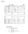
- a data table of the music data 105b including the song text data 103a and the accompaniment music data 103b, the selected music number data 105c and the song tone data 105d, each data being mutually corresponded, is stored.
- the song tone data 105d has four kinds of song tone codes " 0 ", " 1 " , “ 2 “ and “ 3 “, and one song tone code is allotted to each music number.
- the music number with the song tone code " 0 belongs to the genre of the Japanese pops song.
- the music number with the song tone code " 1 " belongs to the genre of the folk song.
- the music number with the song tone code " 2 " belongs to the genre of the country & western music song, further the music number with the song tone code " 3 " belongs to the genre of the jazz song.
- the music data 105b includes the song text data 103a and the accompaniment music data 103b.
- the RF signal with the first frequency is allotted to the music number data 105c which is corresponded to the music number data 105a output through the panel switch 151 and the RF signal with the second frequency is allotted to both the music data 105b and the song tone data 105d.
- a data input/output ( I/O ) device 162 and a modulation-demodulation device 165 are connected between the controller 160 and the head amplifier 166.
- the modulation-demodulation device 165 is able to demodulate the RF signal with the first frequency of the music number data 105a and modulate the music data 105b, the music number data 105c and the song tone data 105d read out from the memory device 163 into the RF signal with the second frequency.
- the controller 160 when the RF signal of the music number data 105a is input to the control apparatus from the music accompanying apparatus through the coaxial cable 154, head amplifier 166, the modulation-demodulation device 165 and the data I/O device 162, the controller 160 reads out from the memory device 163 the music data 105b, the music number data 105c and the song tone data 105d based on the data 105a. And the controller 160 controls the data I/O device 162 and the modulation-demodulation device 165 through the control signal 160b so that the RF signal 165a of both the music data 105b and the music number data 105c read out from the memory device 163 are input to the head amplifier 166. On the other hand, the controller 160 controls the video disc devices 161 and the modulators 164 so that the RF signals 164a of the video picture are input to the head amplifier 166.
- the RF signals 164a, 165a from the modulator 164, the modulation-demodulation device 165 are superimposed each other and transmitted to the music accompanying apparatus through the coaxial cable 154.
- the CPU 105 When the music number data 105a is input to the CPU 105 through the panel switch 151, the CPU 105 outputs the RF signal with the first frequency modulated by the modulation-demodulation device 155 to the control apparatus through the coaxial cable 154.
- the controller 160 receives the music number data 105a (which is obtained by demodulating the RF signal of the music number data 105a passing through the head amplifier 166 in the modulation-demodulation device 165 and input to the controller 160 through the data I/O device 162 ), the music data 105 b, the music number data 105c and the song tone data 105d are read out from the data table stored in the memory device 163 according to the received music number data 105a.
- the RF signals 165a with the second frequency of the music data 105b, the music number data 105c and the song tone data 105d modulated by the modulation-demodulation device 165 after passing through the data I/O device 162, are input to the head amplifier 166.
- the video disc devices 161 are controlled by the controller 160 and the RF signals 164a of the four video picture data modulated by the modulators 164 ( each RF signal 164a having the third frequency, the fourth frequency, the fifth frequency and the sixth frequency, respectively ) are input to the head amplifier 166.
- both the RF signals 165a and 164a are mutually superimposed and transmitted to the music accompanying apparatus through the coaxial cable 154.
- the RF signals of the video picture are directly input to the video tuner 104 and the music number data 105c which is demodulated by the modulation-demodulation device 155 is input to the video tuner 104.
- the video tuner 104 selects one video picture data among the four video picture data according to the music number data 105c and the song tone data 105d, and further reads out the selected video picture data. Thereafter, the video tuner 104 outputs the selected video picture data 104a to the picture synthesizing circuit 108 connected thereto.
- the music data 105b which is obtained by demodulating the RF signal with the second frequency from the coaxial cable 154 by the modulation-demodulation device 155, is temporarily stored in the memory 103 under control by the CPU 105.
- the song text data 103a included in the music data 105 is input to the video picture circuit 106 and thereafter is converted into the text picture data 106a through the video picture circuit 106.
- the text picture data 106a is input to the picture synthesizing circuit 108.
- the video picture data 104a and the text picture data 106a are synthesized into one picture signal 108a which is input to the video monitor 101.
- the video monitor 101 displays the video picture and the song text thereon at the same time, as shown in Fig. 1. Understandable from Fig. 1, the video picture and the song text are displayed on the video monitor 101 with superimposed state.
- the accompaniment music data 103b is converted into the acoustic signal 153a by the sound source 153 and input to the audio amplifier 107.
- the voice signal 109a from the microphone 109 is input to the audio amplifier 107.
- the audio amplifier 107 mixes both the acoustic signal 153a and the voice signal 109a into the sound signal 107a and the speaker 102 sounds the accompaniment music and the voice sung by the user based on the sound signal 107a.
- the video picture and the song text are displayed on the video monitor 101 synchronously with the both the accompaniment music and the voice sounded from the speaker 102.
- a plurality of the music accompanying apparatuses each of the apparatuses having a ID number to identify thereof, are connected to the one control apparatus through the coaxial cable 154. And the controller 160 in the control apparatus repeats polling of each music accompanying apparatus for a predetermined period while specifying the music accompanying apparatus.
- control apparatus if an antenna 90 for receiving television broadcast is connected to the head amplifier 166 as shown in Fig. 3, the control apparatus can transmit the video picture signals received through the antenna 90 to each of the music accompanying apparatus.
- the four video picture data are reproduced from the video disc by the video disc devices 161 and the other data except for the video picture data, such as the music data 105b including the song text data 103a and the accompaniment music data 103b, the music number data 105c, the song tone data 105d, are stored in the memory device 163 separately from the video picture data. And the above all data modulated into the RF signal with inherent frequency are transmitted to the music accompanying apparatus through the coaxial cable 154.
- both the video picture data selected by the video tuner 104 based on the music number data 105c and the song tone data 105d, and the song text data 103a are displayed on the video monitor 101 at the same time.
- both the acoustic signal 153a obtained from the accompaniment music data 103b and the voice signal 109a input from the microphone 109 are sounded from the speaker 102 through the audio amplifier 107.
- the video picture data can be com- monably utilized for the music ( song ) number with the substantially same song tone.
- the video disc size can be miniaturized.
- the size of the control apparatus can be miniaturized and it will be unnecessary so wide area for the control compartment where the control apparatus is installed.
- control system can be effectively utilized in the hotel which has many guest rooms.
- the control apparatus is installed in the control compartment located near the front desk and each music accompanying apparatus is set in each guest room.
- the guest ( user) uses the music accompanying apparatus, both the video picture corresponding to the song tone and the song text are displayed on the video monitor at the same time, and further the accompaniment music is sounded from the speaker by inputting the music ( song ) number through the panel switch. Therefore, the guest can enjoy singing without troublesome operation of the apparatus.
- each television can be utilized as the video monitor of the music accompanying apparatus by only connecting the control apparatus to the common coaxial cable without new wiring works.
- both the control apparatus and the music accompanying apparatus can be connected each other through one common coaxial cable.
- the control system of the first embodiment can readily handle the case in which the same music number is simultaneously selected by the plural music accompanying apparatuses.
- the music accompanying apparatus is essentially comprised of a cable television tuner ( abbreviated as CATV tuner hereinafter) 24, a compact disc player ( abbreviated as CD player hereinafter ) 18 connected to the CATV tuner 24, a video monitor 30 and a pair of speakers 40, each being mutually connected to the CATV tuner 24.
- CATV tuner abbreviated as CATV tuner hereinafter
- CD player compact disc player
- the CATV tuner 24 receives three video pictures transmitted from a coaxial cable 80 through the control apparatus (mentioned hereinafter), each video picture corresponding to a channel A, a channel B and a channel C ( mentioned hereinafter).
- a panel switch 16 and a channel indicator 25 are arranged on the front panel of the CATV tuner 24, a panel switch 16 and a channel indicator 25 are arranged.
- the panel switch 16 is utilized when the user selects desiring song number to sing.
- the channel indicator 25 has three indicating lamps each of which corresponds to the channel A, B and C, and lights one of indicating lamps according to the selected channel through a channel selector 22 ( mentioned hereinafter ).
- a CD 32 on which music data 18c (the music data 18c comprising of a song text data 18a, a song tone data 50 and an accompaniment music data 18b, as mentioned hereinafter) is recorded, is set and both the song text 26a played back by the CD player 18 and the video picture 24a received by the CATV tuner 24 according to the selected channel are displayed on the video monitor 30 at the same time. Further, the accompaniment music played back by the CD player 18 based on the accompaniment music data 18b recorded on the CD 32 and voice sung by the user through a microphone 36 connected to the CATV tuner 24, are output from the speakers 40.
- music data 18c the music data 18c comprising of a song text data 18a, a song tone data 50 and an accompaniment music data 18b, as mentioned hereinafter
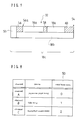
- Fig. 7 the area construction of the music data 18c per one song is schematically shown.
- the song tone data 50 is recorded.
- two recording area are formed parallel with each other.
- the accompaniment music data 18b is recorded.
- two of the song text data 18a are intermittently recorded and a prelude part 56, a interlude part 58 and an ending part 60, in each of which the song text data is not recorded, are formed between the song text data 18a.
- index 56a represents a start position to sing.
- control circuit includes a CPU 10 which wholly controls the music accompanying apparatus, a ROM 12 in which control programs necessary to control the apparatus is stored, a RAM 14 which temporarily stores the music data 18c, etc ( mentioned hereinafter ) and a I/O interface 13, each being mutually connected through bass line.
- a table in which each channel A, B and C of CATV and data representing the song tone data according to the genre thereof are related each other, is stored in the ROM 12.
- the video picture received through the channel A corresponds to the Japanese pops song and the song tone data is defined as " 0 ".
- the video picture received through the channel B corresponds to the folk song and the song tone data is defined as " 1 ".
- the video picture received through the channel C corresponds to the rock & roll music song and the song tone data is defined as " 2 ".
- the panel switch 16 and the CD player 18 which plays back the above music data 18c recorded on the CD 32 set therein, are connected to the I/O interface 13. And the music data 18c read out from the CD 32 by the CD player 18 is temporarily stored in the RAM 14.
- An input terminal of a channel selector 22 is connected to the I/O interface 13 and an output terminal thereof is connected to the CATV tuner 24.
- the channel selector 22 selects one channel among the channels A, B and C of the CATV tuner 24 based on the song tone data 50 read out from the CD 32 under control by the CPU 10.
- the CATV tuner 24 receives the video picture signals with three channels A, Band C from the coaxial cable 80 connected to the control apparatus and selects the video picture signal according to the channel selected by the channel selector 22. Further, the CATV tuner 24 outputs the video picture signal 24a to an input terminal of a picture synthesizer 28.
- An input terminal of a video controller 26 is connected to the I/O interface 13 and an output terminal thereof is connected to another input terminal of the picture synthesizer 28.
- the video controller 26 receives the song text data 18a in the music data 18c stored in the RAM 14 and converts the song text data into a song text picture signal, thereafter the video controller 26 outputs the song text picture signal 26a to the another input terminal of the picture synthesizer 28.
- the picture synthesizer 28 synthesizes both the video picture signal 24a inputfrom the CATV tuner 24 and the song text picture signal 26a input from the video controller 26 and thereafter outputs the synthesized picture signal to the video monitor 30.
- the video monitor 30 displays the synthesized picture comprising of the video picture 24a and the song text 26a thereon, as shown in Fig. 5.
- an input terminal of a D/A converter 34 is connected to the I/O interface 13 and an output terminal thereof is connected to a sound input terminal of an audio amplifier 38 with mixing function.
- the D/A converter 34 receives the accompaniment music data 18b in the music data 18c stored in the RAM 14 and converts the accompaniment music data 18b into the accompaniment music signal 34a, thereafter outputs the accompaniment music signal 34a to the audio amplifier 38 through the sound input terminal thereof.
- the microphone 36 through which voice signal 36a of the user is input is connected to the another sound input terminal of the audio amplifier 38, therefore the audio amplifier 38 mixes the accompaniment music signal 34a from the D/A converter 34 and the voice signal 36a from the microphone 36 and outputs the acoustic signal 38a to the speakers 40. Further, the speakers 40 sounds the accompaniment music and the voice at the same time, based on the acoustic signal 38a.
- the control apparatus according to the second embodiment has essentially the same electric construction as the control apparatus of the first embodiment shown in Fig. 3.
- the different point from the control apparatus of the first embodiment lies in that the I/O device 162, the memory device 163 and the modulation-demodulation device 165 are not arranged in the control apparatus of the second embodiment and only three pairs of the video disc device 71 and the modulator 74 are arranged therein. That is to say, the controller 70 controls three video disc devices 71, each video disc device 71 respectively corresponding to the channel A, the channel B and the channel C, through the control signal 70a at the same time, so that each video disc device 71 reproduces the video picture data 71a recorded on the video disc set therein.
- the video picture received through the channel A corresponds to the Japanese pops song
- the video picture through the channel B to the folk song
- the video picture through the channel C to the rock & roll music song, as shown in Fig 8.
- the user inputs the song number data 16a through the panel switch 16.
- the CPU 10 receives the song number data 16a from the panel switch 16, it outputs the reading command 10a which corresponds to the input song number, to the CD player 18.
- the CD player 18 reads out the music data 18c from the CD 32 according to the reading command 10a and temporarily stores the read out music data 18c in the RAM 14.
- the CPU 10 recognizes the song tone data 50 positioned at the first area of the music data 18c and directs the channel selector 22 so that the selector 22 selects the channel corresponding to the song tone data 50. And the channel selector 22 outputs the selected channel information to the CATV tuner 24.
- the CATV tuner 24 selects the video picture signal among three video picture signals transmitted from the control apparatus, according to the selected channel information. For instance, in case that the song tone data 50 recognized by the CPU 10 is " 2 ", the CPU 10 recognizes that the accompaniment music is the rock & roll music song, referring to the table shown in Fig. 8 and directs the channel selector22 so that the selector 22 selects the channel C. Based on the direction from the channel selector 22, the CATV tuner 24 outputs the video picture signal 24a corresponding to the rock & roll music song, to the picture synthesizer 28.
- the CPU 10 serially outputs the accompaniment music data 18b in the music data 18c stored in the RAM 14, to the D/Acon- verter 34.
- the D/A converter 34 converts the accompaniment music data into the accompaniment music signal 34a and outputs such signal 34a to the audio amplifier 38.
- the audio amplifier 38 amplifies the accompaniment music signal 34a and sounds the speakers 40 according to the amplified accompaniment music signal.
- the CPU 10 outputs the song text data 18a to the video controller 26.
- the video controller 26 generates the song text signal 26a based on the song text data 18a and outputs the signal 26a to the picture synthesizer 28.
- the picture synthesizer 28 synthesizes the video picture signal 24a output from the CATV tuner 24 and the the song text signal 26a output from the video controller 26, into the video picture signal 28a. Thereafter, the picture synthesizer 28 outputs the video picture signal 28a to the video monitor 30 so that the video monitor 30 displays the video picture and the song text at the same time.
- the user starts singing through the microphone 36 when the song text is serially displayed on the video monitor 30.
- the voice input through the microphone 36 is converted into the voice signal 36a which is input to the audio amplifier 38.
- the audio amplifier 38 mixes the accompaniment music signal 34a output from the D/A converter 34 and the voice signal 36a into the acoustic signal 38a. Thereby, the acoustic signal 38a is sounded through the speakers 40.
- the CPU 10 continuously controls each device so that the song text data 18a is synchronized with the accompaniment music data 18b, and further not only displays both the video picture and the song text on the video monitor 30, but also sounds the speakers 40, at the same time.
- the video disc on which the video picture data is recorded is utilized in the video disc device 161 of the control system
- various video picture memory media such as a hard disc ( CD-ROM ) and a video tape, can be utilized in the control apparatus instead of the video disc mentioned above.
- the music data is formed according to Musical Instrument Digital Interface (MIDI ) standard
- MIDI Musical Instrument Digital Interface
- an information to display the song text can be included in the music data in addition to the music information. If the information according to MIDI standard is utilized, it is easy to construct a system in which the data is picked up from an external device through the telecommunication line and thereafter is read out and reproduced. Therefore, if the above system is utilized as the commercial use, new music data can be easily prepared with comparatively low cost for maintaining the system.
- MIDI Musical Instrument Digital Interface
- the same effect as in the above embodiment can be obtained if the channel data of the CATV is recorded in the music data 18c. In this case, it is unnecessary that the table shown in Fig. 4 has to be stored in the ROM 12.
- the video picture signal 24a is automatically selected according to the song tone data in the above embodiment, it is conceivable that the user desirably selects through a channel selecting switch arranged on the panel switch 16.
- the song text signal 26a can be directly input to the picture synthesizer28 without through the video controller 26.
- CATV is utilized as the video picture source in the above embodiment, it can be understood that a ground wave broadcast transmitted from the public or private broadcast board, a broadcast through satellite and a picture data transmitted through fast communication network such as optical fibers are available as the video picture source. Further, the music accompanying apparatus is utilizable in the local area broadcast network.
Abstract
Description
- The present invention relates to a control system for concentratively controlling a plurality of music accompanying apparatuses, each having a video monitor, and particularly relates to the control system including a control apparatus having a video picture signal source through which video picture signals are commonly provided for each of the music accompanying apparatuses.
- Conventionally, as the control system forconcen- tratively controlling a plurality of music accompanying apparatuses each of which has a video monitor, a player system including an auto-exchanger in which many video discs having the recorded video picture data thereon are stored, is generally utilized. Here, the number of the player system is usually set less than the number of the music accompanying apparatuses to a extent that there does not occur any problems at the music accompanying apparatus side. The reason is that the player system can handle a case in which the same music number ( song ) is selected at the same time by the plural music accompanying apparatuses.
- However, in such player system, over one hundred video discs are stored, thus, the player system becomes very big scale. Thus, in case where the number of the player system is set much less than the number of the music accompanying apparatus, there will often occura case in which the player system cannot provide the video picture data with some of the music accompanying apparatuses when the same music number is simultaneously selected by the plural music accompanying apparatuses. Therefore, if the number of the music accompanying apparatus becomes more than the number of the playersystem, it is necessary to prepare many of the big player systems. As a result, a control compartment with wide area has to be retained for the player systems, therefore, the cost becomes very expensive.
- As mentioned above, in case that the playersys- tems are installed in the control compartment with wide area according to the number of the music accompanying apparatus, there are problems that the wide control compartment has to be retained and the cost therefor inevitably becomes expensive. Additionally, the player system has to be seriously changed in the future if the video discs continuously released could not be stored in the auto-exchanger of the player system.
- Accordingly, it is an object of the present invention to overcome the above mentioned problems and to provide a control system of low cost with a compact size in which the video picture data classified corresponding to the song tone, the song category or the genre of the song, can be simultaneously provided for each of the plural music accompanying apparatuses without increasing the number of the player systems if the number of the music accompanying apparatus is increased and further, such video picture data can be provided for each of the music accompanying apparatuses without increasing the number of the video disc if the newly released music is continuously added. Thereby, the size of the control system can be miniaturized and it will be unnecessary so wide area forthe control compartment where the control system is installed.
- In order to accomplish the above object, the present invention comprises a control system including a control apparatus and a plurality of music accompanying apparatuses, comprising;
- a video picture providing means arranged in the control apparatus, for simultaneously providing a plurality of video picture signals each of which is corresponded to a different music genre for each of the music accompanying apparatuses,
- a music selecting means arranged in the music accompanying apparatus, for selecting a music number,
- a video picture selecting means arranged in the music accompanying apparatus, for selecting one video picture signal provided from the video picture providing means based on the genre of the music selected by the music selecting means.
- In the control system of the present invention, a plurality of the video picture signals each of which corresponds to the different music genre, are provided for each of the music accompanying apparatuses through the video picture providing means arranged in the control apparatus. On the other hand, at the music accompanying apparatus side, the music is selected by the music selecting means and thereafter one video picture signal provided from the video picture providing means is selected by the video picture selecting means, based on the genre of the music selected through the music selecting means.
- Therefore, the video pictures provided from the video picture providing means can be commonly utilized for each of the music accompanying apparatuses at the same time. Thus, since it is enough to retain the video picture data corresponding to the number of the music genre at the control apparatus, quantity of the video picture data to be retained by the control apparatus can be reduced, and thereby the control apparatus can be miniaturized. According to this, as a result, the control compartment for the control apparatus can be miniaturized, and further the cost for maintaining the control system can be extremely reduced.
- Further, in each of the music accompanying apparatuses, it is unnecessary to have a reproducer for reproducing the video picture, therefore, the music accompanying apparatus can be simply constructed.
- The invention will be more clearly understood from the following description, given by way of example only with reference to the accompanying drawings in which:
- Fig. 1 is a schematic view of the music accompanying apparatus controlled by a control apparatus in the control system, according to the first embodiment of the present invention,
- Fig. 2 is a block diagram of the music accompanying apparatus shown in Fig. 1,
- Fig. 3 is a block diagram of the control apparatus according to the first embodiment of present invention,
- Fig. 4 is a schematic view of a table stored in a memory device of the control apparatus shown in Fig. 3, which shows a relation between song numbers and the song tone,
- Fig. 5 is a schematic view of the music accompanying apparatus according to the second embodiment of the present invention,
- Fig. 6 is a block diagram of the music accompanying apparatus shown in Fig. 5,
- Fig. 7 is a schematic view which shows the data area recorded on the video disc,
- Fig. 8 is a schematic view of a table stored in a ROM of the music accompanying apparatus shown in Fig. 6, which shows a relation between channels of cable television and data representing the song tone, and
- Fig. 9 is a block diagram of the control apparatus in the control system according to the second embodiment of the present invention.
- A detailed description of the preferred first embodiment of the control system including the control apparatus and a plurality of the music accompanying apparatuses will now be given referring to the accompanying drawings.
- The control system which concentratively controls a plurality of music accompanying apparatuses will be described hereinafter, referring to Fig.s 1 - 4.
- At first, the music accompanying apparatus controlled by the control apparatus ( mentioned hereinafter) will be described according to Fig.s 1 and 3. In Fig. 1, the music accompanying apparatus essentially comprises a
video monitor 101, aspeaker 102, avideo tuner 104, a modulation-demodulation device 155 and anaudio amplifier 107. Here, thevideo monitor 101 displays a song text and a video picture at the same time thereon as mentioned hereinafter. Thespeaker 102 sounds a voice sung by the user through amicrophone 109 connected to theaudio amplifier 107 and an accompaniment music transmitted from the control apparatus shown in Fig. 3. And thevideo tuner 104 has apanel switch 151 on the front side thereof, and through thepanel switch 151, the user selects one of channels, each being corresponded to a video picture classified according to a genre of the accompaniment music transmitted from the control apparatus. Further, the modulation-demodulation device 155 transmits information of the selected music number and receives music data through radio frequency ( RF ) signal. Theaudio amplifier 107 converts both the voice signal from themicrophone 109 and the accompaniment music signal into the acoustic signal. - Following to the above, electric construction of the music accompanying apparatus will be described hereinafter. In Fig. 2, the apparatus is essentially controlled by a
CPU 105. Thepanel switch 151 is connected to theCPU 105, thereby theCPU 105 recognizes the music number based on the input data through thepanel switch 151 and stores the input data in a memory 103 ( described hereinafter). And aROM 152 is connected to theCPU 105. TheROM 152 stores various control programs necessary to control the music accompanying apparatus. TheCPU 105 controls the apparatus according to the control programs stored in theROM 152. - To the
CPU 105, the modulation-demodulation device 155 and thevideo tuner 104 are parallel connected and further both are connected to acoaxial cable 154 which is connected to the control apparatus. Here, the modulation-demodulation device 155 modulates the music number data 105a input through thepanel switch 151 into the RF signal with the first frequency and transmits it to the control apparatus through thecoaxial cable 154, under control by theCPU 105. Additionally, the modulation-demodulation device 155 demodulates the RF signal, which includes a music data 105b including a song text data 103a and anaccompaniment music data 103 b, a selectedmusic number data 105c, asong tone data 105d and four video picture data, each being modulated into the RF signal with the second frequency and transmitted from the control apparatus, as mentioned after. - The
video tuner 104 directly receives the RF signal with the second frequency of the four video picture data from thecoaxial cable 154 and the selectedmusic number data 105c with thesong tone data 105d demodulated by the modulation-demodulation device 155. And thevideo tuner 104 selects one video picture data among the four video picture data according to thesong tone data 105d, and further reads out the selected video picture data. Thereafter, thevideo tuner 104 outputs the selectedvideo picture data 104a to apicture synthesizing circuit 108 connected thereto. - And a
memory 103 is connected to theCPU 105 and further, avideo picture circuit 106 connected to apicture synthesizing circuit 108 and a sound source 153 connected to anaudio amplifier 107 are parallel connected to thememory 103. TheCPU 105 temporarily stores the music data 105b including the song text data 103a and theaccompaniment music data 103b in thememory 103 when received from the modulation-demodulation device 155. Thereafter, theCPU 105 synchronously outputs both thedata 103a and 103b to thevideo picture circuit 106 and to the sound source 153, respectively. - Thereby, the
video picture circuit 106 converts the song text data 103a into a text picture data 106a and outputs it to thepicture synthesizing circuit 108. Thepicture synthesizing circuit 108 synthesizes the selectedvideo picture data 104a from thevideo tuner 104 and the text picture data 106a into onepicture signal 108a and outputs the synthesizedpicture signal 108a to thevideo monitor 101 connected thereto. Thus, thevideo monitor 101 displays the video picture and the song text thereon at the same time. - On the other hand, the sound source 153 converts the
accompaniment music data 103b into anacoustic signal 153a and outputs it to theaudio amplifier 107. Theaudio amplifier 107 mixes theacoustic signal 153a and a voice signal 109a from themicrophone 109, into a mixedsound signal 107a and further outputs the mixedsound signal 107a to thespeaker 102 after amplifying thereof. Thus, thespeaker 102 sounds the accompaniment music and the voice sung by the user at the same time. - Next, referring to Fig.s 3 and 4, the control apparatus which controls the above music accompanying apparatus will be described hereinafter. In Fig. 3, the control apparatus is wholly controlled through a
controller 160 which has well-known CPU, ROM and RAM. To thecontroller 160, fourvideo disc devices 161 are parallel connected. Thecontroller 160outputs control signal 160a to eachvideo disc device 161, thereby controls eachvideo disc device 161. Here, eachvideo disc device 161 is corresponded to one of four genres ( mentioned hereinafter) and reproduces thevideo picture data 161a from a CD set therein, thevideo picture data 161a being video signal formed, in this embodiment, according to National Television System Committee (NTSC) standard (though other standards are equally applicable) and classified according to the song tone ( song genre, mentioned hereinafter ). - Each
video disc device 161 is parallel connected to ahead amplifier 166 through amodulator 164. Themodulator 164 converts the video picture data from thevideo disc device 161 into theRF signal 164a in the frequency band inherent in each channel corresponding to the video picture. Concretely, each of the fourmodulators 164 modulates the video picture data output from each of the fourvideo disc devices 161 into aRF signal 164a with a third frequency, aRF signal 164a with a fourth frequency, aRF signal 164a with a fifth frequency and aRF signal 164a with a sixth frequency, respectively, according to the music genre. Thereafter, each modulator 164 outputs it to thehead amplifier 166. Here, thehead amplifier 166 is able to superimpose the RF signals 164a of the video picture data and theRF signal 165a ( mentioned hereinafter ) obtained by converting the music data 105b, themusic number data 105c and thesong tone data 105d. And thehead amplifier 166 is connected to thecoaxial cable 154 which is joined to the music accompanying apparatus mentioned above. - And a
memory device 163 is connected to thecontroller 160. Thecontroller 160 controls reading out operation from thememory device 163 through thememory control signal 160c. - Here,in the
memory device 163, a data table of the music data 105b including the song text data 103a and theaccompaniment music data 103b, the selectedmusic number data 105c and thesong tone data 105d, each data being mutually corresponded, is stored. The selectedmusic number data 105c which is corresponded to the music number data 105a input through thepanel switch 151, represents the music number such as thesong 1, thesong 2...thesong 9, thesong 10. And thesong tone data 105d has four kinds of song tone codes " 0 ", " 1 " , " 2 " and " 3 ", and one song tone code is allotted to each music number. Here, as clearly understood from the table shown in Fig. 4, the music number with the song tone code " 0 belongs to the genre of the Japanese pops song. The music number with the song tone code " 1 " belongs to the genre of the folk song. And similarly, the music number with the song tone code " 2 " belongs to the genre of the country & western music song, further the music number with the song tone code " 3 " belongs to the genre of the jazz song. Additionally, as mentioned above, the music data 105b includes the song text data 103a and theaccompaniment music data 103b. Here, the RF signal with the first frequency is allotted to themusic number data 105c which is corresponded to the music number data 105a output through thepanel switch 151 and the RF signal with the second frequency is allotted to both the music data 105b and thesong tone data 105d. - Further, a data input/output ( I/O )
device 162 and a modulation-demodulation device 165 are connected between thecontroller 160 and thehead amplifier 166. The modulation-demodulation device 165 is able to demodulate the RF signal with the first frequency of the music number data 105a and modulate the music data 105b, themusic number data 105c and thesong tone data 105d read out from thememory device 163 into the RF signal with the second frequency. Thus, when the RF signal of the music number data 105a is input to the control apparatus from the music accompanying apparatus through thecoaxial cable 154,head amplifier 166, the modulation-demodulation device 165 and the data I/O device 162, thecontroller 160 reads out from thememory device 163 the music data 105b, themusic number data 105c and thesong tone data 105d based on the data 105a. And thecontroller 160 controls the data I/O device 162 and the modulation-demodulation device 165 through thecontrol signal 160b so that theRF signal 165a of both the music data 105b and themusic number data 105c read out from thememory device 163 are input to thehead amplifier 166. On the other hand, thecontroller 160 controls thevideo disc devices 161 and themodulators 164 so that the RF signals 164a of the video picture are input to thehead amplifier 166. - In the
head amplifier 166, theRF signals modulator 164, the modulation-demodulation device 165 are superimposed each other and transmitted to the music accompanying apparatus through thecoaxial cable 154. - Next, operation of the above constructed control apparatus will be described hereinafter. At first, when the music number data 105a is input to the
CPU 105 through thepanel switch 151, theCPU 105 outputs the RF signal with the first frequency modulated by the modulation-demodulation device 155 to the control apparatus through thecoaxial cable 154. In the control apparatus, if thecontroller 160 receives the music number data 105a ( which is obtained by demodulating the RF signal of the music number data 105a passing through thehead amplifier 166 in the modulation-demodulation device 165 and input to thecontroller 160 through the data I/O device 162 ), the music data 105 b, themusic number data 105c and thesong tone data 105d are read out from the data table stored in thememory device 163 according to the received music number data 105a. - And the
RF signals 165a with the second frequency of the music data 105b, themusic number data 105c and thesong tone data 105d modulated by the modulation-demodulation device 165 after passing through the data I/O device 162, are input to thehead amplifier 166. At the same time, thevideo disc devices 161 are controlled by thecontroller 160 and the RF signals 164a of the four video picture data modulated by the modulators 164 ( eachRF signal 164a having the third frequency, the fourth frequency, the fifth frequency and the sixth frequency, respectively ) are input to thehead amplifier 166. Thereafter, both the RF signals 165a and 164a are mutually superimposed and transmitted to the music accompanying apparatus through thecoaxial cable 154. - In the music accompanying apparatus, the RF signals of the video picture are directly input to the
video tuner 104 and themusic number data 105c which is demodulated by the modulation-demodulation device 155 is input to thevideo tuner 104. Thevideo tuner 104 selects one video picture data among the four video picture data according to themusic number data 105c and thesong tone data 105d, and further reads out the selected video picture data. Thereafter, thevideo tuner 104 outputs the selectedvideo picture data 104a to thepicture synthesizing circuit 108 connected thereto. - On the other hand, the music data 105b which is obtained by demodulating the RF signal with the second frequency from the
coaxial cable 154 by the modulation-demodulation device 155, is temporarily stored in thememory 103 under control by theCPU 105. And the song text data 103a included in themusic data 105 is input to thevideo picture circuit 106 and thereafter is converted into the text picture data 106a through thevideo picture circuit 106. The text picture data 106a is input to thepicture synthesizing circuit 108. In thepicture synthesizing circuit 108, thevideo picture data 104a and the text picture data 106a are synthesized into onepicture signal 108a which is input to thevideo monitor 101. As a result, thevideo monitor 101 displays the video picture and the song text thereon at the same time, as shown in Fig. 1. Understandable from Fig. 1, the video picture and the song text are displayed on thevideo monitor 101 with superimposed state. - The
accompaniment music data 103b is converted into theacoustic signal 153a by the sound source 153 and input to theaudio amplifier 107. At the same time, the voice signal 109a from themicrophone 109 is input to theaudio amplifier 107. Thereby, theaudio amplifier 107 mixes both theacoustic signal 153a and the voice signal 109a into thesound signal 107a and thespeaker 102 sounds the accompaniment music and the voice sung by the user based on thesound signal 107a. At this time, the video picture and the song text are displayed on thevideo monitor 101 synchronously with the both the accompaniment music and the voice sounded from thespeaker 102. - Here, a plurality of the music accompanying apparatuses, each of the apparatuses having a ID number to identify thereof, are connected to the one control apparatus through the
coaxial cable 154. And thecontroller 160 in the control apparatus repeats polling of each music accompanying apparatus for a predetermined period while specifying the music accompanying apparatus. - And in the control apparatus, if an
antenna 90 for receiving television broadcast is connected to thehead amplifier 166 as shown in Fig. 3, the control apparatus can transmit the video picture signals received through theantenna 90 to each of the music accompanying apparatus. - As mentioned above, at the control apparatus side, the four video picture data are reproduced from the video disc by the
video disc devices 161 and the other data except for the video picture data, such as the music data 105b including the song text data 103a and theaccompaniment music data 103b, themusic number data 105c, thesong tone data 105d, are stored in thememory device 163 separately from the video picture data. And the above all data modulated into the RF signal with inherent frequency are transmitted to the music accompanying apparatus through thecoaxial cable 154. - Further, at the music accompanying apparatus side, both the video picture data selected by the
video tuner 104 based on themusic number data 105c and thesong tone data 105d, and the song text data 103a, are displayed on thevideo monitor 101 at the same time. And both theacoustic signal 153a obtained from theaccompaniment music data 103b and the voice signal 109a input from themicrophone 109 are sounded from thespeaker 102 through theaudio amplifier 107. - Therefore, the video picture data can be com- monably utilized for the music ( song ) number with the substantially same song tone. Thus, it is unnecessary to record the video picture data every the song number and the data quantity to be recorded on the video disc can be reduced. This leads thatthe video disc size can be miniaturized. As a result, the size of the control apparatus can be miniaturized and it will be unnecessary so wide area for the control compartment where the control apparatus is installed.
- For instance, such control system can be effectively utilized in the hotel which has many guest rooms. In this case, the control apparatus is installed in the control compartment located near the front desk and each music accompanying apparatus is set in each guest room. And when the guest ( user) uses the music accompanying apparatus, both the video picture corresponding to the song tone and the song text are displayed on the video monitor at the same time, and further the accompaniment music is sounded from the speaker by inputting the music ( song ) number through the panel switch. Therefore, the guest can enjoy singing without troublesome operation of the apparatus.
- Similarly, in case that a plurality of the televisions are arranged in one building and each television is mutually connected through the common coaxial cable, each television can be utilized as the video monitor of the music accompanying apparatus by only connecting the control apparatus to the common coaxial cable without new wiring works.
- And in the control system according to the above first embodiment, since a plurality of the video picture signals formed under NSTC standard (or similar) are respectively modulated into the RF signals and the modulated RF signals are transmitted to the music accompanying apparatus, both the control apparatus and the music accompanying apparatus can be connected each other through one common coaxial cable.
- Further, since the video picture signal reproduced by one video disc device is simultaneously received by each music accompanying apparatus and the reproduction of the accompaniment music is conducted by the music accompanying apparatus based on the music data and the song tone data transmitted from the control apparatus, the control system of the first embodiment can readily handle the case in which the same music number is simultaneously selected by the plural music accompanying apparatuses.
- Next, a detailed description of the preferred second embodiment of the control system including the control apparatus and a plurality of the music accompanying apparatuses will now be given referring to the accompanying drawings.
- The control system according to the second embodiment will be described hereinafter, referring to Fig.s 5 - 9.
- At first, the music accompanying apparatus controlled by the control apparatus ( mentioned hereinafter ) will be described according to Fig.s 5 and 8.
- The music accompanying apparatus is essentially comprised of a cable television tuner ( abbreviated as CATV tuner hereinafter) 24, a compact disc player ( abbreviated as CD player hereinafter ) 18 connected to the
CATV tuner 24, avideo monitor 30 and a pair ofspeakers 40, each being mutually connected to theCATV tuner 24. - Here, the
CATV tuner 24 receives three video pictures transmitted from acoaxial cable 80 through the control apparatus (mentioned hereinafter), each video picture corresponding to a channel A, a channel B and a channel C ( mentioned hereinafter). - And on the front panel of the
CATV tuner 24, apanel switch 16 and achannel indicator 25 are arranged. Thepanel switch 16 is utilized when the user selects desiring song number to sing. And thechannel indicator 25 has three indicating lamps each of which corresponds to the channel A, B and C, and lights one of indicating lamps according to the selected channel through a channel selector 22 ( mentioned hereinafter ). - And in the
CD player 18, aCD 32 on whichmusic data 18c ( themusic data 18c comprising of asong text data 18a, asong tone data 50 and anaccompaniment music data 18b, as mentioned hereinafter) is recorded, is set and both thesong text 26a played back by theCD player 18 and the video picture 24a received by theCATV tuner 24 according to the selected channel are displayed on the video monitor 30 at the same time. Further, the accompaniment music played back by theCD player 18 based on theaccompaniment music data 18b recorded on theCD 32 and voice sung by the user through amicrophone 36 connected to theCATV tuner 24, are output from thespeakers 40. - Here, referring to Fig. 7, the
music data 18c recorded on theCD 32 will be described. In Fig. 7, the area construction of themusic data 18c per one song is schematically shown. At first area ( left area in Fig. 7), thesong tone data 50 is recorded. Continuous to thesong tone data 50, two recording area are formed parallel with each other. In one area ( lower area in Fig. 7), theaccompaniment music data 18b is recorded. And in the other area ( upper area in Fig. 7 ), two of thesong text data 18a are intermittently recorded and aprelude part 56, ainterlude part 58 and an endingpart 60, in each of which the song text data is not recorded, are formed between thesong text data 18a. Andindex 56a represents a start position to sing. - Next, electric construction of the music accompanying apparatus will be described referring to Fig. 6. In Fig. 6, control circuit includes a
CPU 10 which wholly controls the music accompanying apparatus, aROM 12 in which control programs necessary to control the apparatus is stored, aRAM 14 which temporarily stores themusic data 18c, etc ( mentioned hereinafter ) and a I/O interface 13, each being mutually connected through bass line. - Here, as shown in Fig. 8, in addition to the control programs, a table in which each channel A, B and C of CATV and data representing the song tone data according to the genre thereof are related each other, is stored in the
ROM 12. In Fig. 8, the video picture received through the channel A corresponds to the Japanese pops song and the song tone data is defined as " 0 ". And the video picture received through the channel B corresponds to the folk song and the song tone data is defined as " 1 ". Further, the video picture received through the channel C corresponds to the rock & roll music song and the song tone data is defined as " 2 ". - Again referring to Fig. 6, the
panel switch 16 and theCD player 18 which plays back theabove music data 18c recorded on theCD 32 set therein, are connected to the I/O interface 13. And themusic data 18c read out from theCD 32 by theCD player 18 is temporarily stored in theRAM 14. - An input terminal of a
channel selector 22 is connected to the I/O interface 13 and an output terminal thereof is connected to theCATV tuner 24. Thus, thechannel selector 22 selects one channel among the channels A, B and C of theCATV tuner 24 based on thesong tone data 50 read out from theCD 32 under control by theCPU 10. TheCATV tuner 24 receives the video picture signals with three channels A, Band C from thecoaxial cable 80 connected to the control apparatus and selects the video picture signal according to the channel selected by thechannel selector 22. Further, theCATV tuner 24 outputs the video picture signal 24a to an input terminal of apicture synthesizer 28. - An input terminal of a
video controller 26 is connected to the I/O interface 13 and an output terminal thereof is connected to another input terminal of thepicture synthesizer 28. Thus, thevideo controller 26 receives thesong text data 18a in themusic data 18c stored in theRAM 14 and converts the song text data into a song text picture signal, thereafter thevideo controller 26 outputs the songtext picture signal 26a to the another input terminal of thepicture synthesizer 28. And thepicture synthesizer 28 synthesizes both the video picture signal 24a inputfrom theCATV tuner 24 and the song text picture signal 26a input from thevideo controller 26 and thereafter outputs the synthesized picture signal to thevideo monitor 30. And the video monitor 30 displays the synthesized picture comprising of the video picture 24a and thesong text 26a thereon, as shown in Fig. 5. - Further, an input terminal of a D/
A converter 34 is connected to the I/O interface 13 and an output terminal thereof is connected to a sound input terminal of anaudio amplifier 38 with mixing function. Thus, the D/A converter 34 receives theaccompaniment music data 18b in themusic data 18c stored in theRAM 14 and converts theaccompaniment music data 18b into the accompaniment music signal 34a, thereafter outputs the accompaniment music signal 34a to theaudio amplifier 38 through the sound input terminal thereof. - And the
microphone 36 through whichvoice signal 36a of the user is input is connected to the another sound input terminal of theaudio amplifier 38, therefore theaudio amplifier 38 mixes the accompaniment music signal 34a from the D/A converter 34 and thevoice signal 36a from themicrophone 36 and outputs the acoustic signal 38a to thespeakers 40. Further, thespeakers 40 sounds the accompaniment music and the voice at the same time, based on the acoustic signal 38a. - Next, the control apparatus which controls the above constructed music accompanying apparatus shown in Fig. 6 will be described hereinafter, referring to Fig. 9.
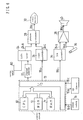
- The control apparatus according to the second embodiment has essentially the same electric construction as the control apparatus of the first embodiment shown in Fig. 3. The different point from the control apparatus of the first embodiment lies in that the I/
O device 162, thememory device 163 and the modulation-demodulation device 165 are not arranged in the control apparatus of the second embodiment and only three pairs of thevideo disc device 71 and themodulator 74 are arranged therein. That is to say, thecontroller 70 controls threevideo disc devices 71, eachvideo disc device 71 respectively corresponding to the channel A, the channel B and the channel C, through thecontrol signal 70a at the same time, so that eachvideo disc device 71 reproduces thevideo picture data 71a recorded on the video disc set therein. And allvideo picture data 71a are modulated by themodulators 74 into the RF signals 74a. Thereafter, the modulatedRF signals 74a are superimposed into theRF signal 76a through thehead amplifier 76 and further theRF signal 76a is transmitted to the music accompanying apparatus through thecoaxial cable 80. Therefore, theRF signal 76a in which threevideo picture data 71 a reproduced by thevideo disc devices 71 are superimposed, is continuously transmitted from the control apparatus to the music accompanying apparatus. - Additionally, operation of the above constructed apparatus will be described hereinafter. Here, the video picture received through the channel A corresponds to the Japanese pops song, the video picture through the channel B to the folk song and the video picture through the channel C to the rock & roll music song, as shown in Fig 8.
- At first, the user inputs the song number data 16a through the
panel switch 16. When theCPU 10 receives the song number data 16a from thepanel switch 16, it outputs the reading command 10a which corresponds to the input song number, to theCD player 18. TheCD player 18 reads out themusic data 18c from theCD 32 according to the reading command 10a and temporarily stores the read outmusic data 18c in theRAM 14. - Thereafter, the
CPU 10 recognizes thesong tone data 50 positioned at the first area of themusic data 18c and directs thechannel selector 22 so that theselector 22 selects the channel corresponding to thesong tone data 50. And thechannel selector 22 outputs the selected channel information to theCATV tuner 24. TheCATV tuner 24 selects the video picture signal among three video picture signals transmitted from the control apparatus, according to the selected channel information. For instance, in case that thesong tone data 50 recognized by theCPU 10 is " 2 ", theCPU 10 recognizes that the accompaniment music is the rock & roll music song, referring to the table shown in Fig. 8 and directs the channel selector22 so that theselector 22 selects the channel C. Based on the direction from thechannel selector 22, theCATV tuner 24 outputs the video picture signal 24a corresponding to the rock & roll music song, to thepicture synthesizer 28. - Next, in order to start playing, the
CPU 10 serially outputs theaccompaniment music data 18b in themusic data 18c stored in theRAM 14, to the D/Acon-verter 34. The D/A converter 34 converts the accompaniment music data into the accompaniment music signal 34a and outputs such signal 34a to theaudio amplifier 38. Thereafter, theaudio amplifier 38 amplifies the accompaniment music signal 34a and sounds thespeakers 40 according to the amplified accompaniment music signal. - On the other hand, when the
accompaniment music data 18b advances to thestart position 56a, theCPU 10 outputs thesong text data 18a to thevideo controller 26. Thevideo controller 26 generates thesong text signal 26a based on thesong text data 18a and outputs thesignal 26a to thepicture synthesizer 28. And thepicture synthesizer 28 synthesizes the video picture signal 24a output from theCATV tuner 24 and the thesong text signal 26a output from thevideo controller 26, into thevideo picture signal 28a. Thereafter, thepicture synthesizer 28 outputs thevideo picture signal 28a to the video monitor 30 so that the video monitor 30 displays the video picture and the song text at the same time. - And the user starts singing through the
microphone 36 when the song text is serially displayed on thevideo monitor 30. The voice input through themicrophone 36 is converted into thevoice signal 36a which is input to theaudio amplifier 38. Further, theaudio amplifier 38 mixes the accompaniment music signal 34a output from the D/A converter 34 and thevoice signal 36a into the acoustic signal 38a. Thereby, the acoustic signal 38a is sounded through thespeakers 40. - Thereafter, the
CPU 10 continuously controls each device so that thesong text data 18a is synchronized with theaccompaniment music data 18b, and further not only displays both the video picture and the song text on thevideo monitor 30, but also sounds thespeakers 40, at the same time. - While the invention has been particularly shown and described with reference to preferred embodiments thereof, it will be understood by those skilled in the art that the foregoing and other changes in form and details can be made therein without departing from the spirit and scope of the invention.
- In the first embodiment, though the video disc on which the video picture data is recorded is utilized in the
video disc device 161 of the control system, various video picture memory media such as a hard disc ( CD-ROM ) and a video tape, can be utilized in the control apparatus instead of the video disc mentioned above. - And in case that the music data is formed according to Musical Instrument Digital Interface ( MIDI ) standard, an information to display the song text can be included in the music data in addition to the music information. If the information according to MIDI standard is utilized, it is easy to construct a system in which the data is picked up from an external device through the telecommunication line and thereafter is read out and reproduced. Therefore, if the above system is utilized as the commercial use, new music data can be easily prepared with comparatively low cost for maintaining the system.
- Further, in the second embodiment, for instance, instead that the
song tone data 50 is recorded in themusic data 18c, the same effect as in the above embodiment can be obtained if the channel data of the CATV is recorded in themusic data 18c. In this case, it is unnecessary that the table shown in Fig. 4 has to be stored in theROM 12. - And though the video picture signal 24a is automatically selected according to the song tone data in the above embodiment, it is conceivable that the user desirably selects through a channel selecting switch arranged on the
panel switch 16. - Further, though three channels A, B and C for selecting the video picture signals are given in the above embodiment as shown in Fig. 8, it is possible that only one channel is given. Though, in such case, it is impossible to select the video picture according to the song tone, it is enjoyable to sing with the video picture displayed on the
video monitor 30. - Additionally, concerning with the
song text data 18a in themusic data 18c, if thesong text signal 26a is directly recorded on theCD 32, thesong text signal 26a can be directly input to the picture synthesizer28 without through thevideo controller 26. - And though the CATV is utilized as the video picture source in the above embodiment, it can be understood that a ground wave broadcast transmitted from the public or private broadcast board, a broadcast through satellite and a picture data transmitted through fast communication network such as optical fibers are available as the video picture source. Further, the music accompanying apparatus is utilizable in the local area broadcast network.
Claims (22)
Applications Claiming Priority (4)
| Application Number | Priority Date | Filing Date | Title |
|---|---|---|---|
| JP3310511A JP2730358B2 (en) | 1991-11-26 | 1991-11-26 | Video karaoke system |
| JP310511/91 | 1991-11-26 | ||
| JP4155220A JP2827704B2 (en) | 1992-06-15 | 1992-06-15 | Centralized management system for karaoke equipment |
| JP155220/92 | 1992-06-15 |
Publications (2)
| Publication Number | Publication Date |
|---|---|
| EP0545635A2 true EP0545635A2 (en) | 1993-06-09 |
| EP0545635A3 EP0545635A3 (en) | 1994-03-02 |
Family
ID=26483277
Family Applications (1)
| Application Number | Title | Priority Date | Filing Date |
|---|---|---|---|
| EP92310828A Withdrawn EP0545635A2 (en) | 1991-11-26 | 1992-11-26 | Control system for controlling a plurality of music accompanying devices |
Country Status (2)
| Country | Link |
|---|---|
| US (1) | US5319452A (en) |
| EP (1) | EP0545635A2 (en) |
Cited By (6)
| Publication number | Priority date | Publication date | Assignee | Title |
|---|---|---|---|---|
| GB2271461A (en) * | 1992-09-18 | 1994-04-13 | Pioneer Electronic Corp | Information reproducing system |
| EP0631283A2 (en) * | 1993-06-22 | 1994-12-28 | Brother Kogyo Kabushiki Kaisha | Image karaoke device |
| EP0665550A2 (en) * | 1994-01-26 | 1995-08-02 | Brother Kogyo Kabushiki Kaisha | Video reproduction device |
| NL1001947C2 (en) * | 1994-12-28 | 1996-10-02 | Samsung Electronics Co Ltd | Karaoke machine with CD player and visual display - shows words of songs and appropriate graphic images as accompaniment to backing music |
| EA000572B1 (en) * | 1998-02-19 | 1999-12-29 | Яков Шоел-Берович Ровнер | Portable musical system for karaoke and cartridge therefor |
| US8315552B2 (en) | 2007-12-31 | 2012-11-20 | Industrial Technology Research Institute | Body interactively learning method and apparatus |
Families Citing this family (24)
| Publication number | Priority date | Publication date | Assignee | Title |
|---|---|---|---|---|
| US5781683A (en) * | 1993-05-14 | 1998-07-14 | Brother Kogyo Kabushiki Kaisha | Video reproducing apparatus with non-repetitive selecting function |
| US5513129A (en) * | 1993-07-14 | 1996-04-30 | Fakespace, Inc. | Method and system for controlling computer-generated virtual environment in response to audio signals |
| JP3398423B2 (en) * | 1993-07-16 | 2003-04-21 | ブラザー工業株式会社 | Data transmission device and terminal device |
| US5488412A (en) * | 1994-03-31 | 1996-01-30 | At&T Corp. | Customer premises equipment receives high-speed downstream data over a cable television system and transmits lower speed upstream signaling on a separate channel |
| TW311196B (en) * | 1994-04-06 | 1997-07-21 | Brother Ind Ltd | |
| JPH07306687A (en) * | 1994-05-13 | 1995-11-21 | Sega Enterp Ltd | Sound reproducing processor and its system |
| JPH08272863A (en) * | 1995-03-30 | 1996-10-18 | Ekushingu:Kk | Information providing system |
| US6174170B1 (en) * | 1997-10-21 | 2001-01-16 | Sony Corporation | Display of text symbols associated with audio data reproducible from a recording disc |
| US6499027B1 (en) | 1998-05-26 | 2002-12-24 | Rockwell Collins, Inc. | System software architecture for a passenger entertainment system, method and article of manufacture |
| US6938258B1 (en) | 1998-05-26 | 2005-08-30 | Rockwell Collins | Message processor for a passenger entertainment system, method and article of manufacture |
| US7028304B1 (en) | 1998-05-26 | 2006-04-11 | Rockwell Collins | Virtual line replaceable unit for a passenger entertainment system, method and article of manufacture |
| US6782392B1 (en) | 1998-05-26 | 2004-08-24 | Rockwell Collins, Inc. | System software architecture for a passenger entertainment system, method and article of manufacture |
| US6807538B1 (en) | 1998-05-26 | 2004-10-19 | Rockwell Collins | Passenger entertainment system, method and article of manufacture employing object oriented system software |
| US6813777B1 (en) | 1998-05-26 | 2004-11-02 | Rockwell Collins | Transaction dispatcher for a passenger entertainment system, method and article of manufacture |
| US5990405A (en) * | 1998-07-08 | 1999-11-23 | Gibson Guitar Corp. | System and method for generating and controlling a simulated musical concert experience |
| US7151214B2 (en) * | 2000-04-07 | 2006-12-19 | Thurdis Developments Limited | Interactive multimedia apparatus |
| US20080163048A1 (en) * | 2006-12-29 | 2008-07-03 | Gossweiler Iii Richard Carl | System and method for displaying multimedia events scheduling information and Corresponding search results |
| US8205230B2 (en) * | 2006-12-29 | 2012-06-19 | Google Inc. | System and method for displaying and searching multimedia events scheduling information |
| US8291454B2 (en) * | 2006-12-29 | 2012-10-16 | Google Inc. | System and method for downloading multimedia events scheduling information for display |
| US8544040B2 (en) | 2006-12-29 | 2013-09-24 | Google Inc. | System and method for displaying multimedia events scheduling information |
| US8972875B2 (en) | 2007-04-24 | 2015-03-03 | Google Inc. | Relevance bar for content listings |
| US8799952B2 (en) | 2007-04-24 | 2014-08-05 | Google Inc. | Virtual channels |
| US9084025B1 (en) | 2007-08-06 | 2015-07-14 | Google Inc. | System and method for displaying both multimedia events search results and internet search results |
| US9975002B2 (en) * | 2015-05-08 | 2018-05-22 | Ross Philip Pinkerton | Synchronized exercising and singing |
Citations (3)
| Publication number | Priority date | Publication date | Assignee | Title |
|---|---|---|---|---|
| JPH01205781A (en) * | 1988-02-12 | 1989-08-18 | Nec Home Electron Ltd | Accompanying music reproducing display device |
| EP0372678A2 (en) * | 1988-12-05 | 1990-06-13 | Tsumura Mihoji | Apparatus for reproducing music and displaying words |
| US5005459A (en) * | 1987-08-14 | 1991-04-09 | Yamaha Corporation | Musical tone visualizing apparatus which displays an image of an animated object in accordance with a musical performance |
Family Cites Families (10)
| Publication number | Priority date | Publication date | Assignee | Title |
|---|---|---|---|---|
| AU503614B2 (en) * | 1975-04-08 | 1979-09-13 | Sony Corporation | Audiovisual teaching system |
| DE3367558D1 (en) * | 1982-08-05 | 1987-01-02 | Nec Corp | Impact printer head capable of printing a dot at a distance narrower than a thickness of a printer unit |
| JPS6097864A (en) * | 1983-11-01 | 1985-05-31 | Matsushita Electric Ind Co Ltd | Printing head |
| US4675568A (en) * | 1984-08-13 | 1987-06-23 | Nec Corporation | Mechanical amplification mechanism for electromechanical transducer |
| JPS61172750A (en) * | 1985-01-29 | 1986-08-04 | Fuji Photo Film Co Ltd | Printing head for wire dot printer and its preparation |
| US4949187A (en) * | 1988-12-16 | 1990-08-14 | Cohen Jason M | Video communications system having a remotely controlled central source of video and audio data |
| US5184901A (en) * | 1989-07-20 | 1993-02-09 | Fujitsu Ltd. | Displacement magnifying mechanism for a print element |
| US5233438A (en) * | 1990-03-02 | 1993-08-03 | Brother Kogyo Kabushiki Kaisha | Entertainment apparatus for producing orchestral music accompaniment and a selected background video |
| JP2538668Y2 (en) * | 1990-03-02 | 1997-06-18 | ブラザー工業株式会社 | Music playback device with message function |
| US5133612A (en) * | 1990-10-03 | 1992-07-28 | Brother Kogyo Kabushiki Kaisha | Dot impact type printing head with adhesively attached base unit |
-
1992
- 1992-11-24 US US07/980,764 patent/US5319452A/en not_active Expired - Lifetime
- 1992-11-26 EP EP92310828A patent/EP0545635A2/en not_active Withdrawn
Patent Citations (3)
| Publication number | Priority date | Publication date | Assignee | Title |
|---|---|---|---|---|
| US5005459A (en) * | 1987-08-14 | 1991-04-09 | Yamaha Corporation | Musical tone visualizing apparatus which displays an image of an animated object in accordance with a musical performance |
| JPH01205781A (en) * | 1988-02-12 | 1989-08-18 | Nec Home Electron Ltd | Accompanying music reproducing display device |
| EP0372678A2 (en) * | 1988-12-05 | 1990-06-13 | Tsumura Mihoji | Apparatus for reproducing music and displaying words |
Non-Patent Citations (1)
| Title |
|---|
| PATENT ABSTRACTS OF JAPAN vol. 13, no. 508 (P-960)15 November 1989 & JP-A-01 205 781 (NEC HOME ELECTRON LTD) * |
Cited By (11)
| Publication number | Priority date | Publication date | Assignee | Title |
|---|---|---|---|---|
| GB2271461A (en) * | 1992-09-18 | 1994-04-13 | Pioneer Electronic Corp | Information reproducing system |
| GB2271461B (en) * | 1992-09-18 | 1996-07-10 | Pioneer Electronic Corp | Information reproducing system |
| EP0631283A2 (en) * | 1993-06-22 | 1994-12-28 | Brother Kogyo Kabushiki Kaisha | Image karaoke device |
| EP0631283A3 (en) * | 1993-06-22 | 1996-05-22 | Brother Ind Ltd | Image karaoke device. |
| US5611693A (en) * | 1993-06-22 | 1997-03-18 | Brother Kogyo Kabushiki Kaisha | Image karaoke device |
| EP0665550A2 (en) * | 1994-01-26 | 1995-08-02 | Brother Kogyo Kabushiki Kaisha | Video reproduction device |
| EP0665550A3 (en) * | 1994-01-26 | 1996-05-29 | Brother Ind Ltd | Video reproduction device. |
| NL1001947C2 (en) * | 1994-12-28 | 1996-10-02 | Samsung Electronics Co Ltd | Karaoke machine with CD player and visual display - shows words of songs and appropriate graphic images as accompaniment to backing music |
| EA000572B1 (en) * | 1998-02-19 | 1999-12-29 | Яков Шоел-Берович Ровнер | Portable musical system for karaoke and cartridge therefor |
| US8315552B2 (en) | 2007-12-31 | 2012-11-20 | Industrial Technology Research Institute | Body interactively learning method and apparatus |
| TWI427573B (en) * | 2007-12-31 | 2014-02-21 | Ind Tech Res Inst | Limb interactively learning method and apparatus |
Also Published As
| Publication number | Publication date |
|---|---|
| US5319452A (en) | 1994-06-07 |
| EP0545635A3 (en) | 1994-03-02 |
Similar Documents
| Publication | Publication Date | Title |
|---|---|---|
| US5319452A (en) | Control system for concentratively controlling a plurality of music accompanying apparatuses | |
| JP3250336B2 (en) | Karaoke system and karaoke terminal device | |
| KR100270988B1 (en) | Recording and regenerating apparatus in microphone | |
| US5416526A (en) | Sound and image reproduction system | |
| RU2178922C1 (en) | Mobile karaoke system | |
| JP3703926B2 (en) | Karaoke equipment | |
| EP0806758A1 (en) | Wireless accompaniment apparatus | |
| JP3868552B2 (en) | Music playback system | |
| JP2730358B2 (en) | Video karaoke system | |
| JP3161108B2 (en) | Centralized management system for audio equipment, centralized management apparatus, and audio equipment | |
| JPH09244668A (en) | Radio music accompaniment device | |
| JPH07281687A (en) | Video 'karaoke' singing equipment | |
| JPH10222184A (en) | Musical sound reproducing device | |
| JP4083712B2 (en) | Karaoke equipment | |
| JP3367653B2 (en) | Sound equipment | |
| JP3676521B2 (en) | Karaoke equipment | |
| JP2827704B2 (en) | Centralized management system for karaoke equipment | |
| JP2945831B2 (en) | Video karaoke equipment | |
| JPH10171478A (en) | Musical sound reproducing device | |
| JP2002055688A (en) | Karaoke equipment | |
| JP3872854B2 (en) | Music playback system | |
| CA2175961A1 (en) | Wireless accompaniment apparatus | |
| JPH10171480A (en) | Musical sound reproducing device | |
| JPH10105185A (en) | Musical sound reproducing system | |
| JPH08278789A (en) | Data distribution system |
Legal Events
| Date | Code | Title | Description |
|---|---|---|---|
| PUAI | Public reference made under article 153(3) epc to a published international application that has entered the european phase |
Free format text: ORIGINAL CODE: 0009012 |
|
| AK | Designated contracting states |
Kind code of ref document: A2 Designated state(s): DE GB |
|
| PUAL | Search report despatched |
Free format text: ORIGINAL CODE: 0009013 |
|
| AK | Designated contracting states |
Kind code of ref document: A3 Designated state(s): DE GB |
|
| 17P | Request for examination filed |
Effective date: 19940627 |
|
| 17Q | First examination report despatched |
Effective date: 19961018 |
|
| GRAG | Despatch of communication of intention to grant |
Free format text: ORIGINAL CODE: EPIDOS AGRA |
|
| GRAG | Despatch of communication of intention to grant |
Free format text: ORIGINAL CODE: EPIDOS AGRA |
|
| GRAH | Despatch of communication of intention to grant a patent |
Free format text: ORIGINAL CODE: EPIDOS IGRA |
|
| STAA | Information on the status of an ep patent application or granted ep patent |
Free format text: STATUS: THE APPLICATION IS DEEMED TO BE WITHDRAWN |
|
| 18D | Application deemed to be withdrawn |
Effective date: 19980117 |