EP0534641A2 - Optical scanner weigh plate mounting apparatus - Google Patents
Optical scanner weigh plate mounting apparatus Download PDFInfo
- Publication number
- EP0534641A2 EP0534641A2 EP92308193A EP92308193A EP0534641A2 EP 0534641 A2 EP0534641 A2 EP 0534641A2 EP 92308193 A EP92308193 A EP 92308193A EP 92308193 A EP92308193 A EP 92308193A EP 0534641 A2 EP0534641 A2 EP 0534641A2
- Authority
- EP
- European Patent Office
- Prior art keywords
- weigh plate
- pivot
- weigh
- mounting apparatus
- plate
- Prior art date
- Legal status (The legal status is an assumption and is not a legal conclusion. Google has not performed a legal analysis and makes no representation as to the accuracy of the status listed.)
- Granted
Links
Images


Classifications
-
- G—PHYSICS
- G01—MEASURING; TESTING
- G01G—WEIGHING
- G01G19/00—Weighing apparatus or methods adapted for special purposes not provided for in the preceding groups
- G01G19/52—Weighing apparatus combined with other objects, e.g. furniture
-
- G—PHYSICS
- G01—MEASURING; TESTING
- G01G—WEIGHING
- G01G21/00—Details of weighing apparatus
- G01G21/23—Support or suspension of weighing platforms
Definitions
- the present invention relates to optical scanner weigh plate mounting apparatus.
- Optical scanners are well known for their usefulness in retail checkout and inventory control.
- Optical scanners may include integral scales for weighing produce.
- Such scales include weigh plates which are flush with the checkout counter.
- the weigh plates have scanning apertures and transparent covers made of glass which collect dust. The weigh plates must be removed periodically to clean or replace the transparent covers and to remove or install scan modules.
- an optical scanner having a weigh plate, characterized by support means for supporting said weigh plate and mounted on weighing means, pivot means having first and second ends, first connection means pivotally coupling said first end of said pivot means to said support means, and second connection means pivotally coupling said second end of said pivot means to said weigh plate.
- the weigh plate mounting apparatus includes no fasteners which require removal in order to gain access to the underside of the weigh plate and to a scan module within the scanner.
- the mounting apparatus can be used in hands-free operating positions during cleaning, removal, maintenance and installation operations.
- a closed position the weigh plate can sit substantially parallel to and above the pivot arms.
- a first opened hands-free position the weigh plate can sit against a first side of the counter to expose the underside of the weigh plate.
- a second opened hands-free position the weigh plate can sit against a second side of the counter to expose the scan module.
- optical scanner 12 includes housing 14, which sits within checkout counter 16. Housing 14 includes lower wall 18 and side walls 20 and 22. Optical scanner 12 further includes weigh plate 24, load cell 26, and scan module 28.
- Weigh plate 24 is flush-mounted with upper surface 126 of counter 16 and has an aperture 32 for passing scanning beams from scan module 28. Mounted on the underside of aperture 32 is a transparent cover 34, which is typically made of glass.
- Weigh plate 24 rests upon load cell 26, which produces an output signal proportional to the weight of a purchased item.
- Weigh plate 24 includes substantially horizontal portion 36, standing portion 38, stabilizing portion 40, and mounting portion 42.
- Standing portion 38 supports weigh plate 24 on upper surface 126 when weigh plate 24 is lifted to expose the inside of housing 14.
- Stabilizing portion 40 acts in conjunction with standing portion 38 to minimize transverse movement of weigh plate 24 and aperture 32 with respect to scan module 28.
- Mounting portion 42 couples weigh plate 24 to weigh plate mounting apparatus 10.
- weigh plate mounting apparatus 10 joins weigh plate 24 with load cell 26.
- weigh plate mounting apparatus 10 includes spacer 44, load distributing member 46 for supporting the weigh plate and mounted on a load cell (26), pivot arms 48 and 50, and pivot pins 52-58. Pivot pins 52 and 54 are mounted on pivot flanges 53 and 55. Spacer 44 rests between load distributing member 46 and load cell 26.
- Load distributing member 46 includes substantially horizontal base portion 60, pivot arm limit portion 62 projecting upwardly from left end 64 of portion 60, and weigh plate support portion 66 projecting upwardly from a point near right end 68 of portion 60. Weigh plate support portion 66 abuts stabilizing portion 40 and right end 68 abuts standing portion 38. Fasteners 70 couple load distributing member 46 and spacer 44 to load cell 26.
- Pivot arms 48 and 50 link weigh plate 24 to load distributing member 46.
- pivot arms 48 and 50 are U-shaped to provide strength and to minimize play over time.
- Pivot pins 52 and 54 join pivot arms 48 and 50 to load distributing member 46 through pivot flanges 53 and 55.
- Fasteners 72 and 74 retain pivot arms 48 and 50 on pivot pins 52 and 54.
- Fasteners 76 and 78 couple pivot flanges 53 and 55 to base portion 60 of load distributing member 46.
- Pivot pins 56 and 58 couple pivot arms 48 and 50 to weigh plate 24. Fasteners 80 and 82 retain pivot arms 48 and 50 on pivot pins 56 and 58.
- gaining access to the underside of weigh plate 24 for cleaning transparent cover 34 involves raising weigh plate 24 about pivot pins 56 and 58 more than ninety degrees in a counter-clockwise direction until weigh plate 24 reaches a stable hands-off position.
- upper surface 84 of weigh plate 24 may lean against edge 86 of upper surface 126 of checkout counter 16, and left edge 88 of weigh plate 24 may rest on scan module 28.
- Pivot arms 48 and 50 preferably come to rest before reaching pivot arm limit portion 62.
- other types of scanners may include different hands-off resting positions which are also envisioned by the present invention.
- gaining access to scan module 28 involves raising weigh plate 24 about pivot pins 56 and 58 in a counter-clockwise direction and raising pivot arms 48 and 50 about pivot pins 52 and 54 more than ninety degrees in a clockwise direction until pivot arms 48 and 50 lean against support portion 66 of load support member 46, and standing portion 38 of weigh plate 24 comes to rest on top of upper surface 126 of checkout counter 16.
- Other types of scanners may include different hands-off resting positions which are also envisioned by the present invention.
- underside 90 of weigh plate 24 may come to rest on top of counter 126 for deep scanner housings.
- weigh plate mounting apparatus 10 offers quick hands-free access for cleaning or for scan module removal without removal of fasteners or housing 14.
Abstract
Description
- The present invention relates to optical scanner weigh plate mounting apparatus.
- Optical scanners are well known for their usefulness in retail checkout and inventory control. Optical scanners may include integral scales for weighing produce. Such scales include weigh plates which are flush with the checkout counter. The weigh plates have scanning apertures and transparent covers made of glass which collect dust. The weigh plates must be removed periodically to clean or replace the transparent covers and to remove or install scan modules.
- Unfortunately, cleaning and replacement of transparent covers and removal of scan modules is difficult in known weigh plate scanners. Typically, the scanner housing must be removed to allow removal of the weigh plate. Removal of the housing is difficult as the housing is fastened to the checkout counter using screws having limited access.
- It is an object of the present invention to provide an optical scanner weigh plate mounting apparatus which does not exhibit the above disadvantages.
- In accordance with the present invention there is provided an optical scanner having a weigh plate, characterized by support means for supporting said weigh plate and mounted on weighing means, pivot means having first and second ends, first connection means pivotally coupling said first end of said pivot means to said support means, and second connection means pivotally coupling said second end of said pivot means to said weigh plate.
- It is an advantageous feature of the present invention that the weigh plate mounting apparatus includes no fasteners which require removal in order to gain access to the underside of the weigh plate and to a scan module within the scanner.
- It is also advantageous that the mounting apparatus can be used in hands-free operating positions during cleaning, removal, maintenance and installation operations. In a closed position, the weigh plate can sit substantially parallel to and above the pivot arms. In a first opened hands-free position, the weigh plate can sit against a first side of the counter to expose the underside of the weigh plate. In a second opened hands-free position, the weigh plate can sit against a second side of the counter to expose the scan module.
- The invention is described further hereinafter, by way of example only, with reference to the accompanying drawings, in which:
- Fig. 1 is a side view of a checkout counter, including weigh plate mounting apparatus embodying the present invention;
- Fig. 2 is an exploded view of the weigh plate mounting apparatus of Fig. 1;
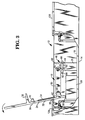
- Fig. 3 is a side view of the checkout counter of Fig. 1 with the weigh plate in a first position; and
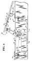
- Fig. 4 is a side view of the checkout counter of Fig. 1 with the weigh plate in a second position.
- Turning now to Fig. 1,
optical scanner 12 includeshousing 14, which sits withincheckout counter 16.Housing 14 includeslower wall 18 andside walls Optical scanner 12 further includesweigh plate 24,load cell 26, andscan module 28. - Weigh
plate 24 is flush-mounted withupper surface 126 ofcounter 16 and has anaperture 32 for passing scanning beams fromscan module 28. Mounted on the underside ofaperture 32 is atransparent cover 34, which is typically made of glass. - Weigh
plate 24 rests uponload cell 26, which produces an output signal proportional to the weight of a purchased item. Weighplate 24 includes substantiallyhorizontal portion 36, standingportion 38, stabilizingportion 40, and mountingportion 42. Standingportion 38 supportsweigh plate 24 onupper surface 126 whenweigh plate 24 is lifted to expose the inside ofhousing 14. Stabilizingportion 40 acts in conjunction with standingportion 38 to minimize transverse movement ofweigh plate 24 andaperture 32 with respect toscan module 28. Mountingportion 42 couplesweigh plate 24 to weighplate mounting apparatus 10. - Weigh
plate mounting apparatus 10 joinsweigh plate 24 withload cell 26. As shown in Figs. 1 and 2, weighplate mounting apparatus 10 includesspacer 44,load distributing member 46 for supporting the weigh plate and mounted on a load cell (26),pivot arms Pivot pins pivot flanges Spacer 44 rests betweenload distributing member 46 andload cell 26. -
Load distributing member 46 includes substantiallyhorizontal base portion 60, pivotarm limit portion 62 projecting upwardly fromleft end 64 ofportion 60, and weighplate support portion 66 projecting upwardly from a point nearright end 68 ofportion 60. Weighplate support portion 66abuts stabilizing portion 40 andright end 68abuts standing portion 38.Fasteners 70 coupleload distributing member 46 andspacer 44 to loadcell 26. -
Pivot arms plate 24 to load distributingmember 46. Preferably,pivot arms -
Pivot pins pivot arms member 46 throughpivot flanges Fasteners pivot arms pivot pins Fasteners couple pivot flanges base portion 60 ofload distributing member 46. -
Pivot pins couple pivot arms plate 24.Fasteners pivot arms pivot pins - Referring now to Figs. 3 and 4, the operation of weigh
plate mounting apparatus 10 is shown in more detail. In Fig. 3, gaining access to the underside ofweigh plate 24 for cleaningtransparent cover 34 involves raisingweigh plate 24 aboutpivot pins weigh plate 24 reaches a stable hands-off position. As shown inscanner 12 of Fig. 3,upper surface 84 ofweigh plate 24 may lean againstedge 86 ofupper surface 126 ofcheckout counter 16, andleft edge 88 ofweigh plate 24 may rest onscan module 28.Pivot arms arm limit portion 62. However, other types of scanners may include different hands-off resting positions which are also envisioned by the present invention. - In Fig. 4, gaining access to
scan module 28 involves raisingweigh plate 24 aboutpivot pins pivot arms pivot pins pivot arms support portion 66 ofload support member 46, and standingportion 38 ofweigh plate 24 comes to rest on top ofupper surface 126 ofcheckout counter 16. Other types of scanners may include different hands-off resting positions which are also envisioned by the present invention. For example,underside 90 ofweigh plate 24 may come to rest on top ofcounter 126 for deep scanner housings. - Advantageously, weigh
plate mounting apparatus 10 offers quick hands-free access for cleaning or for scan module removal without removal of fasteners orhousing 14.
Claims (9)
- An optical scanner having a weigh plate (24), characterized by support means (46) for supporting said weigh plate (24) and mounted on weighing means (26), pivot means (48) having first and second ends, first connection means (54,55) pivotally coupling said first end of said pivot means (48) to said support means, and second connection means (42,58) pivotally coupling said second end of said pivot means to said weigh plate (24).
- Apparatus according to claim 1, characterized by spacer means (44) located between said support means (46) and said weighing means (26), said spacer means (44) serving to position said weigh plate (24) flush with a checkout counter in which the scanner is installed.
- Apparatus according to claim 1 or 2, characterized in that in operation said weigh plate (24) is supported substantially parallel to and above said pivot means (48).
- Apparatus according to any one of claims 1, 2 or 3, characterized in that said weigh plate (24) is rotatable in a first direction about said second end of said pivot means (48) for exposing the underside of said weigh plate (24), and said pivot means (48) is rotatable in a second direction about said support means (46) for exposing a scan module (28) within the apparatus.
- Apparatus according to any one of the preceding claims, characterized in that said support means (46) comprises a base portion (60) having first (64) and second (68) ends, a weigh plate support portion (66) extending upwardly from said base portion (60) at a point near said first end (64), and a pivot means support portion (62) extending upwardly from said base portion (60) at a point near said second end (68) and extending laterally beneath said pivot means (48).
- Apparatus according to any one of the preceding claims, characterized in that said pivot means (48) comprises a U-shaped member.
- Apparatus according to any one of the preceding claims, characterized in that said first connection means (54,55) comprises a flange including vertical and horizontal portions, means (78) for fastening said horizontal portion to said support means (46), a pivot pin extending perpendicularly from said vertical portion, and means (74) attached to the end of said pivot pin for retaining said pivot means (48) on said pivot pin.
- Apparatus according to any one of the preceding claims, characterized in that said second connection means comprises a pivot pin (58) and means (82) attached to the end of this pivot pin (58) for retaining said pivot means (48) and the weigh plate thereon.
- Apparatus according to any one of the preceding claims, characterized by a second pivot arm (50) parallel to said first pivot arm (48) and connected to said distribution member (46) and said weigh plate in a similar manner as said first pivot arm (48).
Applications Claiming Priority (2)
| Application Number | Priority Date | Filing Date | Title |
|---|---|---|---|
| US07/766,996 US5152355A (en) | 1991-09-27 | 1991-09-27 | Optical scanner weigh plate mounting apparatus |
| US766996 | 1991-09-27 |
Publications (3)
| Publication Number | Publication Date |
|---|---|
| EP0534641A2 true EP0534641A2 (en) | 1993-03-31 |
| EP0534641A3 EP0534641A3 (en) | 1993-05-12 |
| EP0534641B1 EP0534641B1 (en) | 1995-12-13 |
Family
ID=25078165
Family Applications (1)
| Application Number | Title | Priority Date | Filing Date |
|---|---|---|---|
| EP92308193A Expired - Lifetime EP0534641B1 (en) | 1991-09-27 | 1992-09-09 | Optical scanner weigh plate mounting apparatus |
Country Status (4)
| Country | Link |
|---|---|
| US (1) | US5152355A (en) |
| EP (1) | EP0534641B1 (en) |
| JP (1) | JPH05210755A (en) |
| DE (1) | DE69206734T2 (en) |
Cited By (2)
| Publication number | Priority date | Publication date | Assignee | Title |
|---|---|---|---|---|
| US9018545B2 (en) | 2012-09-28 | 2015-04-28 | Symbol Technologies, Inc. | Arrangement for and method of preventing overhanging weighing platter of scale from tipping at product checkout system and method of mounting and removing the weighing platter without tools |
| US9747485B2 (en) | 2013-04-16 | 2017-08-29 | Symbol Technologies, Llc | Arrangement for and method of cleaning a platter of a product checkout workstation |
Families Citing this family (6)
| Publication number | Priority date | Publication date | Assignee | Title |
|---|---|---|---|---|
| WO1997007384A1 (en) * | 1995-08-11 | 1997-02-27 | Werner Scholpp | Scale |
| US6481626B1 (en) * | 1998-12-09 | 2002-11-19 | Ncr Corporation | Flush scanner window |
| US20050072603A1 (en) * | 2003-10-03 | 2005-04-07 | Criscione Frank J. | Weigh deck |
| US8400688B2 (en) * | 2010-12-28 | 2013-03-19 | Lexmark International, Inc. | Mounting bracket for image sensing unit of a scanner |
| ES2719457T5 (en) * | 2013-11-08 | 2022-06-20 | Gea Food Solutions Germany Gmbh | Balance with a hinged weighing pan |
| CN111238625A (en) * | 2020-01-16 | 2020-06-05 | 杭州淘控电子商务有限公司 | Price monitoring device and system |
Citations (4)
| Publication number | Priority date | Publication date | Assignee | Title |
|---|---|---|---|---|
| GB2025219A (en) * | 1978-06-19 | 1980-01-23 | Alser Sa | Conveyor belt framework |
| EP0388560A2 (en) * | 1989-03-24 | 1990-09-26 | Spectra Physics Inc. | Data gathering system interface |
| US4971177A (en) * | 1989-03-24 | 1990-11-20 | Spectra-Physics, Inc. | Data gathering system housing/mounting |
| EP0413600A2 (en) * | 1989-08-18 | 1991-02-20 | NCR International, Inc. | Removable window carrier for mounting in a scanner checkout counter |
Family Cites Families (3)
| Publication number | Priority date | Publication date | Assignee | Title |
|---|---|---|---|---|
| JPS5847137U (en) * | 1981-09-22 | 1983-03-30 | 株式会社石田衡器製作所 | Article discharge device in automatic weighing equipment |
| US4789775A (en) * | 1986-10-20 | 1988-12-06 | Ncr Corporation | Optical scanner |
| US4986376A (en) * | 1989-12-01 | 1991-01-22 | Ncr Corporation | Weigh plate quick release mount |
-
1991
- 1991-09-27 US US07/766,996 patent/US5152355A/en not_active Expired - Lifetime
-
1992
- 1992-09-09 EP EP92308193A patent/EP0534641B1/en not_active Expired - Lifetime
- 1992-09-09 DE DE69206734T patent/DE69206734T2/en not_active Expired - Lifetime
- 1992-09-21 JP JP4274863A patent/JPH05210755A/en active Pending
Patent Citations (4)
| Publication number | Priority date | Publication date | Assignee | Title |
|---|---|---|---|---|
| GB2025219A (en) * | 1978-06-19 | 1980-01-23 | Alser Sa | Conveyor belt framework |
| EP0388560A2 (en) * | 1989-03-24 | 1990-09-26 | Spectra Physics Inc. | Data gathering system interface |
| US4971177A (en) * | 1989-03-24 | 1990-11-20 | Spectra-Physics, Inc. | Data gathering system housing/mounting |
| EP0413600A2 (en) * | 1989-08-18 | 1991-02-20 | NCR International, Inc. | Removable window carrier for mounting in a scanner checkout counter |
Cited By (3)
| Publication number | Priority date | Publication date | Assignee | Title |
|---|---|---|---|---|
| US9018545B2 (en) | 2012-09-28 | 2015-04-28 | Symbol Technologies, Inc. | Arrangement for and method of preventing overhanging weighing platter of scale from tipping at product checkout system and method of mounting and removing the weighing platter without tools |
| US9797766B2 (en) | 2012-09-28 | 2017-10-24 | Symbol Technologies, Llc | Application for and method of preventing overhanging weighing platter of scale from tipping at product checkout system and method of mounting and removing the weighing platter without tools |
| US9747485B2 (en) | 2013-04-16 | 2017-08-29 | Symbol Technologies, Llc | Arrangement for and method of cleaning a platter of a product checkout workstation |
Also Published As
| Publication number | Publication date |
|---|---|
| EP0534641B1 (en) | 1995-12-13 |
| EP0534641A3 (en) | 1993-05-12 |
| US5152355A (en) | 1992-10-06 |
| DE69206734D1 (en) | 1996-01-25 |
| JPH05210755A (en) | 1993-08-20 |
| DE69206734T2 (en) | 1996-08-08 |
Similar Documents
| Publication | Publication Date | Title |
|---|---|---|
| US4971177A (en) | Data gathering system housing/mounting | |
| US6237852B1 (en) | Multiple plane weigh platter for multiple plane scanning systems | |
| EP0534641B1 (en) | Optical scanner weigh plate mounting apparatus | |
| US20030115929A1 (en) | Balance with a weighing-load carrier | |
| US20090194595A1 (en) | Scale assembly mounting apparatus for an optical scanner | |
| US5588621A (en) | Universal mounting apparatus and method for bar code scanners | |
| US4700656A (en) | Quick-cleaning, scanning/weighing apparatus | |
| US8365992B2 (en) | Optical scanner with floating load cell frame | |
| BR9600713A (en) | Construction system for rack frames and sub-rack enclosures and cabins | |
| EP0388560A2 (en) | Data gathering system interface | |
| SE9401015L (en) | Wave, especially bathroom scales, and ways to mount it | |
| JPH0317519A (en) | Data acquisition system | |
| CA1084959A (en) | Low profile platform scale accomodating irregularities of supporting surfaces | |
| US4991692A (en) | Spill control mounting for data gathering system | |
| US4036318A (en) | Shop scales with digital weight indication | |
| US5005670A (en) | Method and apparatus for mounting data gathering system | |
| US5308963A (en) | Goods scanning device for sales outlets | |
| GB2160765A (en) | Improvements relating to cabinets or cubicles, suitable for switchgear | |
| US20080149400A1 (en) | Methods and apparatus for multiple support and weight measurement points in a scanner scale combination | |
| WO2023278197A1 (en) | Bioptic barcode reader and bioptic barcod reader assembly | |
| EP0611957B1 (en) | Weighing device, particulary for mounting on a vehicle | |
| US3658144A (en) | Weight platform apparatus in a weighing machine | |
| US6501032B2 (en) | Support device for a weighing cell, and balance incorporating the support device | |
| EP0393323A1 (en) | Mass transducer with electromagnetic compensation | |
| US5779060A (en) | Structure of rack |
Legal Events
| Date | Code | Title | Description |
|---|---|---|---|
| PUAI | Public reference made under article 153(3) epc to a published international application that has entered the european phase |
Free format text: ORIGINAL CODE: 0009012 |
|
| PUAL | Search report despatched |
Free format text: ORIGINAL CODE: 0009013 |
|
| AK | Designated contracting states |
Kind code of ref document: A2 Designated state(s): DE FR GB |
|
| AK | Designated contracting states |
Kind code of ref document: A3 Designated state(s): DE FR GB |
|
| 17P | Request for examination filed |
Effective date: 19931015 |
|
| RAP1 | Party data changed (applicant data changed or rights of an application transferred) |
Owner name: AT&T GLOBAL INFORMATION SOLUTIONS INTERNATIONAL IN |
|
| 17Q | First examination report despatched |
Effective date: 19950210 |
|
| GRAA | (expected) grant |
Free format text: ORIGINAL CODE: 0009210 |
|
| AK | Designated contracting states |
Kind code of ref document: B1 Designated state(s): DE FR GB |
|
| REF | Corresponds to: |
Ref document number: 69206734 Country of ref document: DE Date of ref document: 19960125 |
|
| ET | Fr: translation filed | ||
| PLBE | No opposition filed within time limit |
Free format text: ORIGINAL CODE: 0009261 |
|
| STAA | Information on the status of an ep patent application or granted ep patent |
Free format text: STATUS: NO OPPOSITION FILED WITHIN TIME LIMIT |
|
| 26N | No opposition filed | ||
| REG | Reference to a national code |
Ref country code: FR Ref legal event code: CD |
|
| REG | Reference to a national code |
Ref country code: GB Ref legal event code: IF02 |
|
| REG | Reference to a national code |
Ref country code: GB Ref legal event code: 746 Effective date: 20030624 |
|
| REG | Reference to a national code |
Ref country code: FR Ref legal event code: D6 |
|
| PGFP | Annual fee paid to national office [announced via postgrant information from national office to epo] |
Ref country code: FR Payment date: 20100903 Year of fee payment: 19 |
|
| PGFP | Annual fee paid to national office [announced via postgrant information from national office to epo] |
Ref country code: GB Payment date: 20100927 Year of fee payment: 19 |
|
| PGFP | Annual fee paid to national office [announced via postgrant information from national office to epo] |
Ref country code: DE Payment date: 20100830 Year of fee payment: 19 |
|
| GBPC | Gb: european patent ceased through non-payment of renewal fee |
Effective date: 20110909 |
|
| REG | Reference to a national code |
Ref country code: FR Ref legal event code: ST Effective date: 20120531 |
|
| PG25 | Lapsed in a contracting state [announced via postgrant information from national office to epo] |
Ref country code: DE Free format text: LAPSE BECAUSE OF NON-PAYMENT OF DUE FEES Effective date: 20120403 |
|
| REG | Reference to a national code |
Ref country code: DE Ref legal event code: R119 Ref document number: 69206734 Country of ref document: DE Effective date: 20120403 |
|
| PG25 | Lapsed in a contracting state [announced via postgrant information from national office to epo] |
Ref country code: GB Free format text: LAPSE BECAUSE OF NON-PAYMENT OF DUE FEES Effective date: 20110909 Ref country code: FR Free format text: LAPSE BECAUSE OF NON-PAYMENT OF DUE FEES Effective date: 20110930 |