EP0534136A1 - Closure with protective cap - Google Patents
Closure with protective cap Download PDFInfo
- Publication number
- EP0534136A1 EP0534136A1 EP92114256A EP92114256A EP0534136A1 EP 0534136 A1 EP0534136 A1 EP 0534136A1 EP 92114256 A EP92114256 A EP 92114256A EP 92114256 A EP92114256 A EP 92114256A EP 0534136 A1 EP0534136 A1 EP 0534136A1
- Authority
- EP
- European Patent Office
- Prior art keywords
- closure element
- closure
- element according
- connector part
- cap
- Prior art date
- Legal status (The legal status is an assumption and is not a legal conclusion. Google has not performed a legal analysis and makes no representation as to the accuracy of the status listed.)
- Granted
Links
Images

Classifications
-
- A—HUMAN NECESSITIES
- A61—MEDICAL OR VETERINARY SCIENCE; HYGIENE
- A61J—CONTAINERS SPECIALLY ADAPTED FOR MEDICAL OR PHARMACEUTICAL PURPOSES; DEVICES OR METHODS SPECIALLY ADAPTED FOR BRINGING PHARMACEUTICAL PRODUCTS INTO PARTICULAR PHYSICAL OR ADMINISTERING FORMS; DEVICES FOR ADMINISTERING FOOD OR MEDICINES ORALLY; BABY COMFORTERS; DEVICES FOR RECEIVING SPITTLE
- A61J1/00—Containers specially adapted for medical or pharmaceutical purposes
- A61J1/05—Containers specially adapted for medical or pharmaceutical purposes for collecting, storing or administering blood, plasma or medical fluids ; Infusion or perfusion containers
- A61J1/10—Bag-type containers
Definitions
- the invention relates to a closure element for an outlet opening of a container, a hose or a tube with a connector part, which is provided with a central channel-shaped recess and can be fastened to the outlet opening, and with a recess which closes the recess to the outside and has a predetermined breaking point the cap part connected to the connector part.
- a closure element of the type mentioned is known from US Pat. No. 4,899,903. Furthermore, a similar closure element is described in US Pat. No. 4,915,704.
- the closure elements shown there are designed in the form of a pipe closure which has a cap which can be broken off via a line of weakness. In both cases, the closure element is pushed onto a part of the hose or tube that is tapered in cross-section, which results in the disadvantage that the hose or tube must be specially adapted to the closure element.
- a further disadvantage arises with regard to the breaking off process itself, since it is not ensured that the free hose or pipe end is not damaged by the breaking off process.
- US Pat. No. 4,303,067 which forms the closest prior art, shows a closure element, in particular for a medical bag, which is welded between two bag films and has a breakable cap part.
- the disadvantage here is that the breakable cap part is not protected against unwanted actuation, so that when handling the bag there is a risk that the cap part breaks off at the predetermined breaking point.
- EP-A1-11 144 also shows a closure for a bag, in which a cap part or closure element can be separated from the connector part by means of a pull ring.
- This is a solution in which the closure element is torn open.
- the disadvantage is that on the one hand considerable forces are required for tearing open and on the other hand there is always the risk that the tear ring itself will tear off and / or the closure element will not be opened sufficiently. By applying a tensile force to open the closure, there is still the possibility that the remaining bag will be damaged or its contents may leak out in an undesired manner.
- AT-PS 322 113 describes a medical container, the dispensing opening of which is closed with a conical cap. The cap is pushed over the dispensing opening, no break-off arrangement is provided. As a result, sterilization and handling have many disadvantages.
- a container with a breakable cap part is also known from WO 84/03436.
- the invention has for its object to provide a closure element of the type described, which can be used for a variety of applications with a simple structure and simple, reliable handling, can be sterilized easily and reliably and enables the undisturbed outflow of the fluid through the opened closure element.
- the closure element according to the invention is characterized by a number of significant advantages.
- the closure membrane provides the possibility of continuing to seal the outlet opening of the hose or tube or of the container to the environment after breaking off the cap part. At least penetration of contaminating particles or the like is avoided, so that the subsequent connection of the closure element with an exclusion element or the like can result in an unimpeded outflow.
- This has the further advantage that there is no need for additional closure or valve elements in the interior of the container, hose or tube can be.
- the closure membrane is designed as an elastic membrane. This can be made of rubber or the like, for example, so that the membrane can be pierced to remove the liquid.
- the membrane can also have a slotted design, as a result of which the individual wings of the membrane open when a pouring or draining element is inserted and enable an unimpeded flow of fluid.
- a detachable protective cap is applied over the cap part and at least part of the connector part.
- This protective cap prevents the cap part from accidentally breaking off and at the same time serves as tamper-evident. It is particularly advantageous if the protective cap is screwed to the connector part by means of a thread. In this way, an easy and targeted loosening of the protective cap can be achieved without the risk that the operating personnel accidentally breaks off the cap part when loosening the protective cap.
- the protective cap it is also possible to couple the protective cap to break off the cap part when the protective cap is released, for example by means of an integrated mechanism or the like, so that when the protective cap is removed or unscrewed, the cap part is broken off at the same time.
- the connector part in the connection area of the cap part has a cylindrical recess of larger diameter than the channel-shaped recess into which the membrane is inserted and into which a pipe socket of the cap part can be inserted.
- the pipe socket of the cap part thus squeezes the disk-shaped closure membrane, so that it does not have to be attached by additional measures. At the same time, a secure connection of the cap part to the connector part is ensured, which can be sufficiently tight to ensure an excellent seal during sterilization and in the sterilized state.
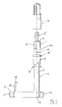
- the closure element shown in FIGS. 1 and 2 can be connected to a hose or tube 12, the tube or hose 12 not having to be adapted to the closure element. Rather, the closure element comprises a tubular connecting tube 11 which is bevelled on its front side and which can be inserted into the hose or the tube. Adjacent to the connecting pipe 11 is a collar 13 which serves as a stop for a protective cap 7 to be described below.
- the connecting pipe 11 has a free, central cross section, which is only slightly smaller than the cross section of the outlet opening 1 of the pipe or hose 12.
- a cylindrical tube-shaped area Adjacent to the collar 13, a cylindrical tube-shaped area is provided on the closure element, which has a cylindrical recess 9, the diameter of which is larger than the diameter of the connecting tube.
- the transition to the cylindrical recess 9 takes place via a shoulder 14, against which a disk-shaped closure membrane 6 can be placed.
- a pipe socket 10 is inserted, which, as can be seen from FIG. 1, clamps the closure membrane 6 together with paragraph 14.
- the pipe socket 10 is connected via a predetermined breaking point 4 to a cap part 5, which seals the outlet opening 1 or the central interior of the closure element to the environment and can be broken off if necessary.
- a thread 8 is provided, which can be single or multiple threads.
- the thread 8 serves to screw the protective cap 7 shown in FIG. 2 onto the closure element in order to cover both the cap part and the pipe socket 10 connected to it, as well as the connector part 2 of the closure element and protect against damage.
- the closure element according to the invention has the following advantages: the flow rate through the channel-shaped recess 3 of the closure element can be greater than 1.51 / min. Furthermore, no parts required for sealing are provided, which can penetrate into the outlet opening 1 in an uncontrolled manner and thus into the container, the tube or the hose. In particular, additional sealing elements can essentially be dispensed with, otherwise the particulate loading of the sealing elements is zero. Furthermore, the cap part 5 ensures a tamper-evident closure, so that it can be easily and immediately determined whether the closure element has already been opened. Since the connector part 2 has a connecting tube 11, the closure element can be connected to any container, etc.
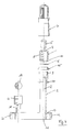
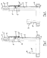
- FIGS. 3 to 6 differ from the exemplary embodiment of FIGS. 1 and 2 initially in that an additional ring seal 15 is provided in order to seal the protective cap 7 against the connector part 2 when the closure cap 7 is screwed on.
- This seal enables the protective cap 7 to be screwed on tightly even after the cap part 5 has broken.
- the tubular connector part 2 is provided with a flange 20.
- the exemplary embodiments further show that the tubular Connector part 2 is integrally connected to a base element 17, the channel-shaped recess 3 of the connector part 2 opening into an inlet chamber 16 of the base element 17.
- the foot element 17 has a boat-like shape in plan view, it has two convexly outwardly curved side walls which converge at an acute angle on side edges 21, 22. The plate-like foot element 17 can thus be welded into the seam of a foil bag.
- cap part 5 can be provided with corrugation or profiling in order to facilitate the breaking off process.
- a filler neck 18 is also formed on the foot element 17, the interior of which is connected to the inlet chamber 16.
- the filler neck 18 is sealed from the environment by means of a pierceable closure element 19.
- the closure element 19 can, for example, as shown in FIG. 4, be in the form of a pierceable ball made of silicone or rubber. This is inserted into a cylindrical mounting element 23, which is connected in one piece to the filler neck 18, and the ball is clamped by bending or flanging the edge of the mounting element 23.
- the foot element 17 can, for example, be made of polycarbonate or a similar material in order to facilitate welding into a foil bag.
Abstract
Description
Die Erfindung bezieht sich auf ein Verschlußelement für eine Austrittsöffnung eines Behälters, eines Schlauches oder eines Rohres mit einem Konnektorteil, welches mit einer zentrischen kanalförmigen Ausnehmung versehen ist und an der Austrittsöffnung befestigbar ist, sowie einem die Ausnehmung nach außen abschließenden, eine Sollbrechstelle aufweisenden, mit dem Konnektorteil verbundenen Kappenteil.The invention relates to a closure element for an outlet opening of a container, a hose or a tube with a connector part, which is provided with a central channel-shaped recess and can be fastened to the outlet opening, and with a recess which closes the recess to the outside and has a predetermined breaking point the cap part connected to the connector part.
Ein Verschlußelement der genannten Art ist aus der US-PS 4,899,903 bekannt. Weiterhin wird ein ähnliches Verschlußelement in der US-PS 4,915,704 beschrieben. Die dort gezeigten Verschlußelemente sind in Form eines Rohrverschlußes ausgebildet, welcher eine Kappe aufweist, die über eine Schwächungslinie abgebrochen werden kann. In beiden Fällen ist das Verschlußelement auf einen im Querschnitt verjüngten Teil des Schlauches oder Rohres aufgeschoben, woraus sich der Nachteil ergibt, daß der Schlauch bzw. das Rohr speziell an das Verschlußelement angepaßt werden müssen. Ein weiterer Nachteil ergibt sich hinsichtlich des Abbrechvorganges selbst, da nicht sichergestellt ist, daß durch den Abbrechvorgang nicht auch das freie Schlauch- bzw. Rohrende beschädigt wird.A closure element of the type mentioned is known from US Pat. No. 4,899,903. Furthermore, a similar closure element is described in US Pat. No. 4,915,704. The closure elements shown there are designed in the form of a pipe closure which has a cap which can be broken off via a line of weakness. In both cases, the closure element is pushed onto a part of the hose or tube that is tapered in cross-section, which results in the disadvantage that the hose or tube must be specially adapted to the closure element. A further disadvantage arises with regard to the breaking off process itself, since it is not ensured that the free hose or pipe end is not damaged by the breaking off process.
Aus der US-PS 3,994,412 ist ein weiteres Verschlußelement bekannt, bei welchem zusätzlich ein in das Lumen des Schlauches oder Rohres eingreifender Stopfen Vorgesehen ist.Another closure element is known from US Pat. No. 3,994,412, in which an additional plug is provided which engages in the lumen of the hose or tube.
Ein weiterer Nachteil der bekannten Verschlußelemente liegt darin, daß diese zu Undichtigkeiten während der Sterilisation im autoklaven neigen und somit, insbesondere auch im Hinblick auf den Nachweis der Originalität, eines weiteren Sicherungsmittels, beispielsweise einer Vakuum-Verpackung bedürfen.Another disadvantage of the known closure elements is that they tend to leak during sterilization in the autoclave and therefore, especially with a view to verifying the originality, require a further securing means, for example vacuum packaging.
Die US-PS 4,303,067, welche den nächstkommenden Stand der Technik bildet, zeigt ein Verschlußelement, insbesondere für einen medizinischen Beutel, welches zwischen zwei Beutelfolien eingeschweißt ist und ein abbrechbares Kappenteil aufweist. Nachteilig hierbei ist, daß das abbrechbare Kappenteil nicht vor ungewollter Betätigung geschützt ist, so daß bei der Handhabung des Beutels die Gefahr besteht, daß das Kappenteil an der Sollbruchstelle abbricht.US Pat. No. 4,303,067, which forms the closest prior art, shows a closure element, in particular for a medical bag, which is welded between two bag films and has a breakable cap part. The disadvantage here is that the breakable cap part is not protected against unwanted actuation, so that when handling the bag there is a risk that the cap part breaks off at the predetermined breaking point.
Die EP-A1-11 144 zeigt ebenfalls einen Verschluß für einen Beutel, bei welchem mittels eines Zugringes ein Kappenteil oder Verschlußelement von dem Konnektorteil getrennt werden kann. Es handelt sich hierbei um eine Lösung, bei welcher das Verschlußelement aufgerissen wird. Nachteilig hierbei ist, daß zum einen erhebliche Kräfte zum Aufreißen erforderlich sind und daß zum anderen stets die Gefahr besteht, daß der Aufreißring selbst abreißt und/oder das Verschlußelement nicht ausreichend geöffnet wird. Durch die Aufbringung einer Zugkraft zum Öffnen des Verschlusses besteht weiterhin die Möglichkeit, daß der restliche Beutel beschädigt wird oder dessen Inhalt in ungewünschter Weise austritt.EP-A1-11 144 also shows a closure for a bag, in which a cap part or closure element can be separated from the connector part by means of a pull ring. This is a solution in which the closure element is torn open. The disadvantage here is that on the one hand considerable forces are required for tearing open and on the other hand there is always the risk that the tear ring itself will tear off and / or the closure element will not be opened sufficiently. By applying a tensile force to open the closure, there is still the possibility that the remaining bag will be damaged or its contents may leak out in an undesired manner.
Die AT-PS 322 113 beschreibt einen medizinischen Behälter, dessen Ausgabeöffnung mit einer konischen Kappe geschlossen ist. Die Kappe wird über die Ausgabeöffnung aufgeschoben, es ist keine Abbrechanordnung vorgesehen. Hieraus ergibt sich, daß die Sterilisierung ebenso wie die Handhabung vielfältige Nachteile aufweisen.AT-PS 322 113 describes a medical container, the dispensing opening of which is closed with a conical cap. The cap is pushed over the dispensing opening, no break-off arrangement is provided. As a result, sterilization and handling have many disadvantages.
Ein Behälter mit einem abbrechbaren Kappenteil ist auch aus der WO 84/03436 bekannt. Bei dieser Ausgestaltungsform erweist es sich als nachteilig, daß nach einem Abbrechen des Kappenteiles der Behälterinnenraum nicht zur Umgebung hin verschlossen ist, so daß, da keine Verschlußmembrane verhanden ist, der Behälterinnenraum zur Umgebung hin vollständig geöffnet ist.A container with a breakable cap part is also known from WO 84/03436. In this embodiment, it proves disadvantageous that after breaking off the cap part the container interior is not closed to the environment, so that since there is no sealing membrane, the container interior is completely open to the environment.
Ein weiterer Ausgabebehälter für medizinische Zwecke ist aus der AU-PS 414 085 vorbekannt. Der hierbei vorgesehene Flaschenhals ist mittels eines Verschlußstopfens verschlossen, durch Drehen einer Kappe erfolgt ein Bruch einer Sollbruchstelle, so daß der Stopfen herausgezogen werden kann. Auch hierbei erweist es sich als nachteilig, daß der Innenraum des Behälters nach dem einmaligen Öffnen vollständig der Umgebung ausgesetzt ist, so daß eine Verschlußmembrane, welche beispielsweise mittels einer Spritze durchstoßen werden könnte, nicht vorgesehen ist. Eine ähnliche Ausgestaltungsform zeigt auch die US-PS 3,346,146.Another dispenser for medical purposes is previously known from AU-PS 414 085. The bottle neck provided here is closed by means of a sealing plug, a predetermined breaking point is broken by turning a cap, so that the plug can be pulled out. Here, too, it proves disadvantageous that the interior of the container is completely exposed to the environment after it has been opened once, so that a closure membrane, which could be pierced by a syringe, for example, is not provided. A similar embodiment is also shown in US Pat. No. 3,346,146.
Der Erfindung liegt die Aufgabe zugrunde, ein Verschlußelement der eingangs beschriebenen Art zu schaffen, welches bei einfachem Aufbau und einfacher, betriebssicherer Handhabbarkeit für vielfältige Anwendungszwecke verwendbar ist, leicht und betriebssicher sterilisierbar ist und die ungestörte Ausströmung des Fluids durch das geöffnete Verschlußelement ermöglicht.The invention has for its object to provide a closure element of the type described, which can be used for a variety of applications with a simple structure and simple, reliable handling, can be sterilized easily and reliably and enables the undisturbed outflow of the fluid through the opened closure element.
Erfindungsgemäß wird die Aufgabe durch die Merkmale des Hauptanspruches gelöst, die Unteransprüche zeigen weitere vorteilhafte Ausgestaltungen der Erfindung.According to the invention the object is achieved by the features of the main claim, the subclaims show further advantageous embodiments of the invention.
Das erfindungsgemäße Verschlußelement zeichnet sich durch eine Reihe erheblicher Vorteile aus. Durch die Verschlußmembrane ergibt sich die Möglichkeit, nach dem Abbrechen des Kappenteiles die Austrittsöffnung des Schlauches oder Rohres bzw. des Behälters weiterhin zur Umgebung hin abzudichten. Es wird zumindest ein Eindringen von kontaminierenden Partikeln oder ähnlichem vermieden, so daß durch das anschließende Verbinden des Verschlußelementes mit einem Ausschlußelement oder ähnlichem eine ungehinderte Ausströmung erfolgen kann. Daraus ergibt sich der weitere Vorteil, daß auf zusätzliche Verschluß- bzw. Ventilelemente im Inneren des Behälters, Schlauches oder Rohres verzichtet werden kann.The closure element according to the invention is characterized by a number of significant advantages. The closure membrane provides the possibility of continuing to seal the outlet opening of the hose or tube or of the container to the environment after breaking off the cap part. At least penetration of contaminating particles or the like is avoided, so that the subsequent connection of the closure element with an exclusion element or the like can result in an unimpeded outflow. This has the further advantage that there is no need for additional closure or valve elements in the interior of the container, hose or tube can be.
In einer bevorzugten Weiterbildung der Erfindung ist vorgesehen, daß die Verschlußmembrane als elastische Membrane ausgebildet ist. Diese kann beispielsweise aus Gummi oder ähnlichem gefertigt sein, so daß zur Entnahme der Flüssigkeit ein Durchstechen der Membrane möglich ist. Die Membrane kann jedoch auch geschlitzt ausgebildet sein, wodurch sich die einzelnen Flügel der Membrane beim Einführen eines Ausgieß- oder Ablaßelementes öffnen und eine ungehinderte Fluidströmung ermöglichen.In a preferred development of the invention it is provided that the closure membrane is designed as an elastic membrane. This can be made of rubber or the like, for example, so that the membrane can be pierced to remove the liquid. However, the membrane can also have a slotted design, as a result of which the individual wings of the membrane open when a pouring or draining element is inserted and enable an unimpeded flow of fluid.
Besonders günstig ist, wenn erfindungsgemäß über das Kappenteil und zumindest einen Teil des Konnektorteiles eine lösbare Schutzkappe aufgebracht ist. Diese Schutzkappe verhindert ein ungewolltes Abbrechen des Kappenteiles und dient gleichzeitig als Originalitätssicherung. Besonders günstig ist es dabei, wenn die Schutzkappe mittels eines Gewindes mit dem Konnektorteil verschraubt ist. Hierdurch läßt sich ein leichtes und gezieltes Lösen der Schutzkappe erreichen, ohne daß die Gefahr besteht, daß das Bedienungspersonal beim Lösen der Schutzkappe ausversehen bereits das Kappenteil abbricht.It is particularly favorable if, according to the invention, a detachable protective cap is applied over the cap part and at least part of the connector part. This protective cap prevents the cap part from accidentally breaking off and at the same time serves as tamper-evident. It is particularly advantageous if the protective cap is screwed to the connector part by means of a thread. In this way, an easy and targeted loosening of the protective cap can be achieved without the risk that the operating personnel accidentally breaks off the cap part when loosening the protective cap.
Alternativ hierzu ist es weiterhin möglich, die Schutzkappe zum Abbrechen des Kappenteiles beim Lösen der Schutzkappe mit dieser zu koppeln, beispielsweise mittels einer integrierten Mechanik oder ähnlichem, so daß beim Abziehen oder Abschrauben der Schutzkappe zugleich das Kappenteil abgebrochen wird.Alternatively, it is also possible to couple the protective cap to break off the cap part when the protective cap is released, for example by means of an integrated mechanism or the like, so that when the protective cap is removed or unscrewed, the cap part is broken off at the same time.
Weiterhin ist es besonders vorteilhaft, wenn das Konnektorteil im Anschlußbereich des Kappenteiles eine zylindrische Ausnehmung größeren Durchmessers als die kanalförmige Ausnehmung aufweist, in welche die Membrane eingesetzt ist und in welche ein Rohrstutzen des Kappenteiles einbringbar ist.Furthermore, it is particularly advantageous if the connector part in the connection area of the cap part has a cylindrical recess of larger diameter than the channel-shaped recess into which the membrane is inserted and into which a pipe socket of the cap part can be inserted.
Der Rohrstutzen des Kappenteiles quetscht somit die scheibenförmige Verschlußmembrane, so daß diese nicht durch zusätzliche Maßnahmen befestigt werden muß. Gleichzeitig ist eine sichere Verbindung des Kappenteiles mit dem Konnektorteil gewährleistet, welche in ausreichendem Maße dicht ausgebildet sein kann, um eine hervorragende Abdichtung während der Sterilisierung sowie im sterilisierten Zustand zu gewährleisten.The pipe socket of the cap part thus squeezes the disk-shaped closure membrane, so that it does not have to be attached by additional measures. At the same time, a secure connection of the cap part to the connector part is ensured, which can be sufficiently tight to ensure an excellent seal during sterilization and in the sterilized state.
Im folgenden wird die Erfindung anhand von Ausführungsbeispielen in Verbindung mit der Zeichnung beschrieben.
Dabei zeigt:
- Fig. 1
- eine Seitenansicht, teils im Schnitt, eines Ausführungsbeispiels des erfindungsgemäßen Verschlußelementes,
- Fig. 2
- eine Seitenansicht, ähnlich Fig. 1, mit einer zusätzlich angebrachten Schutzkappe,
- Fig. 3
- eine Seitenansicht, teils im Schnitt, eines weiteren Ausführungsbeispieles der Erfindung im nicht montierten Zustand in explosionsartiger Darstellung,
- Fig. 4
- eine Ansicht eines weiteren Ausführungsbeispieles, ähnlich Fig. 3,
- Fig. 5
- eine Seitenansicht des in Fig. 3 gezeigten Ausführungsbeispieles im montierten Zustand, und
- Fig. 6
- eine Seitenansicht des in Fig. 4 gezeigten Ausführungsbeispieles im montierten Zustand.
It shows:
- Fig. 1
- 2 shows a side view, partly in section, of an exemplary embodiment of the closure element according to the invention,
- Fig. 2
- 2 shows a side view, similar to FIG. 1, with an additionally attached protective cap,
- Fig. 3
- 3 shows a side view, partly in section, of a further exemplary embodiment of the invention in the unassembled state in an exploded view,
- Fig. 4
- 3 shows a view of a further exemplary embodiment, similar to FIG. 3,
- Fig. 5
- a side view of the embodiment shown in Fig. 3 in the assembled state, and
- Fig. 6
- a side view of the embodiment shown in Fig. 4 in the assembled state.
In der nachfolgenden Figurenbeschreibung sind gleiche Teile mit gleichen Bezugsziffern versehen.In the following description of the figures, the same parts are provided with the same reference numbers.
Das in den Fig. 1 und 2 gezeigte Verschlußelement kann mit einem Schlauch oder Rohr 12 verbunden werden, wobei das Rohr bzw. der Schlauch 12 nicht an das Verschlußelement angepaßt werden muß. Vielmehr umfaßt das Verschlußelement ein rohrförmiges, an seiner Vorderseite abgeschrägtes Anschlußrohr 11, welches in den Schlauch bzw. das Rohr einschiebbar ist. Angrenzend an das Anschlußrohr 11 ist ein Bund 13 vorgesehen, welcher als Anschlag für eine im nachfolgenden noch zu beschreibende Schutzkappe 7 dient. Das Anschlußrohr 11 weist einen freien, zentrischen Querschnitt auf, welcher nur geringfügig kleiner ist, als der Querschnitt der Austrittsöffnung 1 des Rohres bzw. Schlauches 12.The closure element shown in FIGS. 1 and 2 can be connected to a hose or
Angrenzend an den Bund 13 ist an dem Verschlußelement ein zylinderrohrförmiger Bereich vorgesehen, welcher eine zylindrische Ausnehmung 9 aufweist, deren Durchmesser größer ist, als der Durchmesser des Anschlußrohres. Der Übergang zu der zylindrischen Ausnehmung 9 erfolgt über einen Absatz 14, gegen welchen eine scheibenförmige Verschluß-Membrane 6 anlegbar ist. In die zylindrische Ausnehmung 9 ist ein Rohrstutzen 10 eingeführt, welcher wie aus Fig. 1 ersichtlich ist, die Verschlußmembrane 6 zusammen mit Absatz 14 klemmt.Adjacent to the
Der Rohrstutzen 10 ist über eine Sollbrechstelle 4 mit einem Kappenteil 5 verbunden, welches die Austrittsöffnung 1 bzw. den zentrischen Innenraum des Verschlußelementes zur Umgebung hin abdichtet und bei Bedarf abgebrochen werden kann.The
Auf der Außenseite des Rohrstutzens 10 ist ein Gewinde 8 vorgesehen, welches ein- oder mehrgängig sein kann. Das Gewinde 8 dient dazu, die in Fig. 2 gezeigt Schutzkappe 7 auf das Verschlußelement aufzuschrauben, um sowohl das Kappenteil und den damit verbundenen Rohrstutzen 10, als auch das Konnektorteil 2 des Verschlußelementes zu decken und gegen Beschädigungen zu schützen.On the outside of the
Das erfindungsgemäße Verschlußelement weist die folgenden Vorteile auf: die Fließgeschwindigkeit durch die kanalförmige Ausnehmung 3 des Verschlußelementes kann größer sein, als 1,51/min. Weiterhin sind keine zur Abdichtung benötigten Teile vorgesehen, welche unkontrolliert in die Austrittsöffnung 1 und damit in den Behälter, das Rohr oder den Schlauch eindringen können. Insbesondere kann im wesentlichen auf zusätzliche Dichtelemente verzichtet werden, im übrigen ist die partikuläre Belastung der Dichtelemente gleich null. Weiterhin gewährleistet das Kappenteil 5 einen Originalitätsverschluß, so daß leicht und sofort festgestellt werden kann, ob das Verschlußelement bereits geöffnet wurde. Da das Konnektorteil 2 ein Anschlußrohr 11 aufweist, ist das Verschlußelement an beliebigen Behältern etc. konnektierbar. Weiterhin ergibt sich die Möglichkeit, nach Entfernen des Kappenteiles 5 übliche Entnahmesysteme zu installieren, welche auch zum Öffnen der Verschlußmembrane 6 dienen können. Nach Entfernung der Entnahmesysteme nach Beendigung der Anwendung führt die Verschlußmembrane 6 wieder zu einer Abdichtung, so daß kein Nachlaufen einer Restlösung oder ähnlichem auftritt.The closure element according to the invention has the following advantages: the flow rate through the channel-shaped
Die in den Fig. 3 bis 6 gezeigten Ausführungsbeispiele unterscheiden sich von dem Ausführungsbeispiel der Fig. 1 und 2 zunächst darin, daß eine zusätzliche Ringdichtung 15 vorgesehen ist, um die Schutzkappe 7 gegenüber dem Konnektorteil 2 abzudichten, wenn die Verschlußkappe 7 aufgeschraubt ist. Diese Abdichtung ermöglicht es, die Schutzkappe 7 auch nach einem Brechen des Kappenteiles 5 wieder dicht aufzuschrauben. Um die Abdichtung zu gewährleisten, ist das rohrförmige Konnektorteil 2 mit einem Flansch 20 versehen.The exemplary embodiments shown in FIGS. 3 to 6 differ from the exemplary embodiment of FIGS. 1 and 2 initially in that an
Die Ausführungsbeispiele zeigen weiterhin, daß das rohrförmige Konnektorteil 2 einstückig mit einem Fußelement 17 verbunden ist, wobei die kanalförmige Ausnehmung 3 des Konnektorteiles 2 in eine Einlaßkammer 16 des Fußelementes 17 mündet. Das Fußelement 17 weist in der Draufsicht eine schiffchenartige Form auf, es besitzt zwei konvex nach außen gebogene Seitenwandungen, welche in einem spitzen Winkel an seitlichen Kanten 21, 22 zusammenlaufen. Somit kann das plattenartige Fußelement 17 in die Naht eines Folienbeutels eingeschweißt werden.The exemplary embodiments further show that the
Wie die Fig. 3 bis 6 weiterhin zeigen, kann das Kappenteil 5 mit einer Riffelung oder Profilierung versehen sein, um den Abbrechvorgang zu erleichtern.3 to 6 also show, the
An dem Fußelement 17 ist weiterhin ein Zufüllstutzen 18 ausgebildet, dessen Innenraum mit der Einlaßkammer 16 in Verbindung steht. Der Zufüllstutzen 18 ist mittels eines durchstechbaren Verschlußelementes 19 zur Umgebung hin abgedichtet. Das Verschlußelement 19 kann beispielsweise, wie in Fig. 4 gezeigt, in Form einer durchstechbaren Kugel aus Silikon oder Gummi ausgebildet sein. Diese wird in ein zylindrisches Halterungselement 23, welches einstückig mit dem Zufüllstutzen 18 verbunden ist, eingesetzt, eine Klemmung der Kugel erfolgt durch Umbiegen oder durch Umbörteln des Randes des Halterungselementes 23.A
Das Fußelement 17 kann beispielsweise aus Polycarbonat oder einem ähnlichen Werkstoff gefertigt sein, um ein Einschweißen in einen Folienbeutel zu erleichtern.The
Mittels des Zufüllstutzens 18 ist es möglich, zusätzlich Flüssigkeit zuzuführen oder abzuziehen.By means of the
Die Erfindung ist nicht auf das gezeigte Ausführungsbeispiel beschränkt, vielmehr ergeben sich für den Fachmann im Rahmen der Erfindung vielfältige Abwandlungs- und Modifikationsmöglichkeiten.The invention is not limited to the exemplary embodiment shown, but there are various modifications and variations for the person skilled in the art within the scope of the invention Modification options.
Claims (14)
Applications Claiming Priority (2)
| Application Number | Priority Date | Filing Date | Title |
|---|---|---|---|
| DE9110460U | 1991-08-23 | ||
| DE9110460U DE9110460U1 (en) | 1991-08-23 | 1991-08-23 |
Publications (2)
| Publication Number | Publication Date |
|---|---|
| EP0534136A1 true EP0534136A1 (en) | 1993-03-31 |
| EP0534136B1 EP0534136B1 (en) | 1996-07-03 |
Family
ID=6870549
Family Applications (1)
| Application Number | Title | Priority Date | Filing Date |
|---|---|---|---|
| EP92114256A Expired - Lifetime EP0534136B1 (en) | 1991-08-23 | 1992-08-20 | Closure with protective cap |
Country Status (3)
| Country | Link |
|---|---|
| EP (1) | EP0534136B1 (en) |
| AT (1) | ATE139899T1 (en) |
| DE (2) | DE9110460U1 (en) |
Cited By (2)
| Publication number | Priority date | Publication date | Assignee | Title |
|---|---|---|---|---|
| EP0930056A3 (en) * | 1998-01-20 | 1999-11-24 | Bracco International B.V. | Universal connector |
| US11013662B2 (en) | 2014-12-19 | 2021-05-25 | Fresenius Kabi Deutschland Gmbh | Connector system comprising at least two withdrawal ports |
Families Citing this family (1)
| Publication number | Priority date | Publication date | Assignee | Title |
|---|---|---|---|---|
| FR2833483B1 (en) * | 2001-12-17 | 2004-09-24 | Technoflex Ind | PERFUSER MOUTHPIECE FOR FLEXIBLE POCKET FOR MEDICAL USE |
Citations (6)
| Publication number | Priority date | Publication date | Assignee | Title |
|---|---|---|---|---|
| FR2396699A1 (en) * | 1977-07-05 | 1979-02-02 | Aguettant Lab | Seal for sterile flexible container - has sealing disc inserted in between flanged ends or open and blind connector stems |
| EP0011144A1 (en) * | 1978-10-27 | 1980-05-28 | Biotest-Serum-Institut GmbH | Closure for a plastic bag containing an infusion solution |
| US4303067A (en) * | 1980-01-21 | 1981-12-01 | American Hospital Supply Corporation | Medical liquid bag having an improved additive port |
| EP0083778A2 (en) * | 1982-01-07 | 1983-07-20 | Fresenius AG | Preservation bag |
| US4723687A (en) * | 1981-03-16 | 1988-02-09 | Franz Kutterer | Tube with screw cap |
| US4915704A (en) * | 1988-06-27 | 1990-04-10 | Terumo Kabushiki Kaisha | Tube assembly with a breakaway plug |
Family Cites Families (9)
| Publication number | Priority date | Publication date | Assignee | Title |
|---|---|---|---|---|
| BE789393Q (en) * | 1966-02-25 | 1973-01-15 | Scherico Ltd | COMBINED DISPENSER DISPENSING FLUIDS IN THE FORM OF DROPS, SPRAY OR FOAM |
| AT322113B (en) * | 1971-11-26 | 1975-05-12 | Roncales Sa | CONTAINER WITH A TUBE FOR INJECTION OF MEDICINAL PRODUCTS |
| US4000739A (en) * | 1975-07-09 | 1977-01-04 | Cordis Corporation | Hemostasis cannula |
| US4133312A (en) * | 1976-10-13 | 1979-01-09 | Cordis Dow Corp. | Connector for attachment of blood tubing to external arteriovenous shunts and fistulas |
| DE2817102C2 (en) * | 1978-04-19 | 1985-01-24 | Dr. Eduard Fresenius, Chemisch-pharmazeutische Industrie KG, 6380 Bad Homburg | Connector for plastic cannulas or venous catheters |
| JPS5519160A (en) * | 1978-07-28 | 1980-02-09 | Terumo Corp | Protector for sampling needle of blood body fluids sampler |
| DE3000903C1 (en) * | 1980-01-11 | 1989-09-21 | Fresenius Chem Pharm Ind | Connection device for connecting cannulas, catheters or tubing |
| SE8301193D0 (en) * | 1983-03-04 | 1983-03-04 | Haustrup Plastic As | cONTAINER |
| DE3809127C1 (en) * | 1988-03-18 | 1989-04-13 | B. Braun Melsungen Ag, 3508 Melsungen, De |
-
1991
- 1991-08-23 DE DE9110460U patent/DE9110460U1/de not_active Expired - Lifetime
-
1992
- 1992-08-20 AT AT92114256T patent/ATE139899T1/en active
- 1992-08-20 EP EP92114256A patent/EP0534136B1/en not_active Expired - Lifetime
- 1992-08-20 DE DE59206694T patent/DE59206694D1/en not_active Expired - Lifetime
Patent Citations (6)
| Publication number | Priority date | Publication date | Assignee | Title |
|---|---|---|---|---|
| FR2396699A1 (en) * | 1977-07-05 | 1979-02-02 | Aguettant Lab | Seal for sterile flexible container - has sealing disc inserted in between flanged ends or open and blind connector stems |
| EP0011144A1 (en) * | 1978-10-27 | 1980-05-28 | Biotest-Serum-Institut GmbH | Closure for a plastic bag containing an infusion solution |
| US4303067A (en) * | 1980-01-21 | 1981-12-01 | American Hospital Supply Corporation | Medical liquid bag having an improved additive port |
| US4723687A (en) * | 1981-03-16 | 1988-02-09 | Franz Kutterer | Tube with screw cap |
| EP0083778A2 (en) * | 1982-01-07 | 1983-07-20 | Fresenius AG | Preservation bag |
| US4915704A (en) * | 1988-06-27 | 1990-04-10 | Terumo Kabushiki Kaisha | Tube assembly with a breakaway plug |
Cited By (2)
| Publication number | Priority date | Publication date | Assignee | Title |
|---|---|---|---|---|
| EP0930056A3 (en) * | 1998-01-20 | 1999-11-24 | Bracco International B.V. | Universal connector |
| US11013662B2 (en) | 2014-12-19 | 2021-05-25 | Fresenius Kabi Deutschland Gmbh | Connector system comprising at least two withdrawal ports |
Also Published As
| Publication number | Publication date |
|---|---|
| ATE139899T1 (en) | 1996-07-15 |
| DE9110460U1 (en) | 1991-10-10 |
| EP0534136B1 (en) | 1996-07-03 |
| DE59206694D1 (en) | 1996-08-08 |
Similar Documents
| Publication | Publication Date | Title |
|---|---|---|
| EP2301622B1 (en) | Connector for packaging containing medical fluids and packaging for medical fluids | |
| EP2114345B1 (en) | Closure cap for a container for receiving medical liquids, and container for receiving medical liquids | |
| DE102008048988A1 (en) | Device for connecting a syringe to a container or a hose line | |
| DE102004009918B4 (en) | Arrangement for storing, transporting and applying a preferably medical liquid | |
| DE10139291A1 (en) | Packaging unit, in particular, for throw away filters comprises a housing and a cover element which has a central piercing point and at least one planned tearing line | |
| WO2003099191A1 (en) | Connector for packaging containing medical fluids and packaging for medical fluids | |
| DE2419435A1 (en) | INJECTION SYRINGE | |
| EP0803267A2 (en) | Medical connection device | |
| EP0811560A2 (en) | Tamper-evident closure for neck-like container apertures | |
| EP3233016B1 (en) | Connector system comprising at least two outlet ports | |
| DE3006292A1 (en) | Rupturable container closure element, blood bag provided with such a closure element, and method for closing a flexible container with such a closure element | |
| EP0534136B1 (en) | Closure with protective cap | |
| DE2825450A1 (en) | SEPARABLE, ONE-PIECE BLOOD DONOR HOSE CONNECTION | |
| EP3104928B1 (en) | Device for connecting medical disposable articles in a sterile manner | |
| EP2421597B1 (en) | Frangible closure to obstruct a flexible tube | |
| DE3217913C2 (en) | Sterile containers for medical purposes | |
| DE4410875A1 (en) | Bag assembly for fluid delivery to a patient | |
| WO2014012692A1 (en) | Plastic closure for opening an aseptically sealed tubular plastic bag | |
| WO2021122268A1 (en) | Connector and connection system for a medical packaging, and method for providing a liquid for a medical packaging | |
| EP0766956A1 (en) | Container for medical liquid | |
| DE3244151A1 (en) | Medical storage bag | |
| EP0819440A2 (en) | Infusion set | |
| EP0343534B1 (en) | Container for preserving liquids, in particular bodily liquids | |
| EP2712603B1 (en) | Medical container | |
| EP1721595B1 (en) | Container for providing medical fluids |
Legal Events
| Date | Code | Title | Description |
|---|---|---|---|
| PUAI | Public reference made under article 153(3) epc to a published international application that has entered the european phase |
Free format text: ORIGINAL CODE: 0009012 |
|
| AK | Designated contracting states |
Kind code of ref document: A1 Designated state(s): AT BE CH DE DK ES FR GB GR IE IT LI LU MC NL PT SE |
|
| 17P | Request for examination filed |
Effective date: 19930925 |
|
| 17Q | First examination report despatched |
Effective date: 19950220 |
|
| GRAH | Despatch of communication of intention to grant a patent |
Free format text: ORIGINAL CODE: EPIDOS IGRA |
|
| RBV | Designated contracting states (corrected) |
Designated state(s): AT CH DE LI |
|
| GRAH | Despatch of communication of intention to grant a patent |
Free format text: ORIGINAL CODE: EPIDOS IGRA |
|
| GRAA | (expected) grant |
Free format text: ORIGINAL CODE: 0009210 |
|
| AK | Designated contracting states |
Kind code of ref document: B1 Designated state(s): AT CH DE LI |
|
| REF | Corresponds to: |
Ref document number: 139899 Country of ref document: AT Date of ref document: 19960715 Kind code of ref document: T |
|
| REF | Corresponds to: |
Ref document number: 59206694 Country of ref document: DE Date of ref document: 19960808 |
|
| PLBE | No opposition filed within time limit |
Free format text: ORIGINAL CODE: 0009261 |
|
| STAA | Information on the status of an ep patent application or granted ep patent |
Free format text: STATUS: NO OPPOSITION FILED WITHIN TIME LIMIT |
|
| 26N | No opposition filed | ||
| PGFP | Annual fee paid to national office [announced via postgrant information from national office to epo] |
Ref country code: CH Payment date: 20110829 Year of fee payment: 20 |
|
| PGFP | Annual fee paid to national office [announced via postgrant information from national office to epo] |
Ref country code: DE Payment date: 20110831 Year of fee payment: 20 Ref country code: AT Payment date: 20110830 Year of fee payment: 20 |
|
| REG | Reference to a national code |
Ref country code: DE Ref legal event code: R071 Ref document number: 59206694 Country of ref document: DE |
|
| REG | Reference to a national code |
Ref country code: DE Ref legal event code: R071 Ref document number: 59206694 Country of ref document: DE |
|
| REG | Reference to a national code |
Ref country code: CH Ref legal event code: PL |
|
| REG | Reference to a national code |
Ref country code: AT Ref legal event code: MK07 Ref document number: 139899 Country of ref document: AT Kind code of ref document: T Effective date: 20120820 |
|
| PG25 | Lapsed in a contracting state [announced via postgrant information from national office to epo] |
Ref country code: DE Free format text: LAPSE BECAUSE OF EXPIRATION OF PROTECTION Effective date: 20120821 |