EP0532313A1 - Twin plate cathode assembly for multiplate electrochemical cells - Google Patents
Twin plate cathode assembly for multiplate electrochemical cells Download PDFInfo
- Publication number
- EP0532313A1 EP0532313A1 EP92308220A EP92308220A EP0532313A1 EP 0532313 A1 EP0532313 A1 EP 0532313A1 EP 92308220 A EP92308220 A EP 92308220A EP 92308220 A EP92308220 A EP 92308220A EP 0532313 A1 EP0532313 A1 EP 0532313A1
- Authority
- EP
- European Patent Office
- Prior art keywords
- cathode
- twin plate
- cell
- twin
- cathode structure
- Prior art date
- Legal status (The legal status is an assumption and is not a legal conclusion. Google has not performed a legal analysis and makes no representation as to the accuracy of the status listed.)
- Granted
Links
Images

Classifications
-
- H—ELECTRICITY
- H01—ELECTRIC ELEMENTS
- H01M—PROCESSES OR MEANS, e.g. BATTERIES, FOR THE DIRECT CONVERSION OF CHEMICAL ENERGY INTO ELECTRICAL ENERGY
- H01M10/00—Secondary cells; Manufacture thereof
- H01M10/04—Construction or manufacture in general
- H01M10/0413—Large-sized flat cells or batteries for motive or stationary systems with plate-like electrodes
-
- H—ELECTRICITY
- H01—ELECTRIC ELEMENTS
- H01M—PROCESSES OR MEANS, e.g. BATTERIES, FOR THE DIRECT CONVERSION OF CHEMICAL ENERGY INTO ELECTRICAL ENERGY
- H01M10/00—Secondary cells; Manufacture thereof
- H01M10/04—Construction or manufacture in general
- H01M10/045—Cells or batteries with folded plate-like electrodes
-
- H—ELECTRICITY
- H01—ELECTRIC ELEMENTS
- H01M—PROCESSES OR MEANS, e.g. BATTERIES, FOR THE DIRECT CONVERSION OF CHEMICAL ENERGY INTO ELECTRICAL ENERGY
- H01M4/00—Electrodes
- H01M4/02—Electrodes composed of, or comprising, active material
- H01M4/06—Electrodes for primary cells
-
- H—ELECTRICITY
- H01—ELECTRIC ELEMENTS
- H01M—PROCESSES OR MEANS, e.g. BATTERIES, FOR THE DIRECT CONVERSION OF CHEMICAL ENERGY INTO ELECTRICAL ENERGY
- H01M6/00—Primary cells; Manufacture thereof
- H01M6/14—Cells with non-aqueous electrolyte
-
- H—ELECTRICITY
- H01—ELECTRIC ELEMENTS
- H01M—PROCESSES OR MEANS, e.g. BATTERIES, FOR THE DIRECT CONVERSION OF CHEMICAL ENERGY INTO ELECTRICAL ENERGY
- H01M2300/00—Electrolytes
- H01M2300/0017—Non-aqueous electrolytes
- H01M2300/002—Inorganic electrolyte
-
- H—ELECTRICITY
- H01—ELECTRIC ELEMENTS
- H01M—PROCESSES OR MEANS, e.g. BATTERIES, FOR THE DIRECT CONVERSION OF CHEMICAL ENERGY INTO ELECTRICAL ENERGY
- H01M6/00—Primary cells; Manufacture thereof
- H01M6/14—Cells with non-aqueous electrolyte
- H01M6/18—Cells with non-aqueous electrolyte with solid electrolyte
- H01M6/182—Cells with non-aqueous electrolyte with solid electrolyte with halogenide as solid electrolyte
-
- Y—GENERAL TAGGING OF NEW TECHNOLOGICAL DEVELOPMENTS; GENERAL TAGGING OF CROSS-SECTIONAL TECHNOLOGIES SPANNING OVER SEVERAL SECTIONS OF THE IPC; TECHNICAL SUBJECTS COVERED BY FORMER USPC CROSS-REFERENCE ART COLLECTIONS [XRACs] AND DIGESTS
- Y02—TECHNOLOGIES OR APPLICATIONS FOR MITIGATION OR ADAPTATION AGAINST CLIMATE CHANGE
- Y02E—REDUCTION OF GREENHOUSE GAS [GHG] EMISSIONS, RELATED TO ENERGY GENERATION, TRANSMISSION OR DISTRIBUTION
- Y02E60/00—Enabling technologies; Technologies with a potential or indirect contribution to GHG emissions mitigation
- Y02E60/10—Energy storage using batteries
-
- Y—GENERAL TAGGING OF NEW TECHNOLOGICAL DEVELOPMENTS; GENERAL TAGGING OF CROSS-SECTIONAL TECHNOLOGIES SPANNING OVER SEVERAL SECTIONS OF THE IPC; TECHNICAL SUBJECTS COVERED BY FORMER USPC CROSS-REFERENCE ART COLLECTIONS [XRACs] AND DIGESTS
- Y02—TECHNOLOGIES OR APPLICATIONS FOR MITIGATION OR ADAPTATION AGAINST CLIMATE CHANGE
- Y02P—CLIMATE CHANGE MITIGATION TECHNOLOGIES IN THE PRODUCTION OR PROCESSING OF GOODS
- Y02P70/00—Climate change mitigation technologies in the production process for final industrial or consumer products
- Y02P70/50—Manufacturing or production processes characterised by the final manufactured product
-
- Y—GENERAL TAGGING OF NEW TECHNOLOGICAL DEVELOPMENTS; GENERAL TAGGING OF CROSS-SECTIONAL TECHNOLOGIES SPANNING OVER SEVERAL SECTIONS OF THE IPC; TECHNICAL SUBJECTS COVERED BY FORMER USPC CROSS-REFERENCE ART COLLECTIONS [XRACs] AND DIGESTS
- Y10—TECHNICAL SUBJECTS COVERED BY FORMER USPC
- Y10T—TECHNICAL SUBJECTS COVERED BY FORMER US CLASSIFICATION
- Y10T29/00—Metal working
- Y10T29/49—Method of mechanical manufacture
- Y10T29/49002—Electrical device making
- Y10T29/49108—Electric battery cell making
- Y10T29/49114—Electric battery cell making including adhesively bonding
Definitions
- This invention relates to the art of lithium batteries, and more particularly to a new and improved twin plate cathode structure and assembly method for use in a alkali metal/solid cathode and alkali metal/oxyhalide cell assembly.
- the principles of the new and improved cathode structure of the present invention can be applied to a variety of alkali metal/solid cathode and alkali metal/oxyhalide cells.
- one area of use of the present invention is with a cell for an implantable cardiac defibrillator such as that disclosed in United States Patent 4,830,940.
- Other alkali metal/solid cathode cells which may utilize the cathode structure of the present invention include metal oxide, metal oxide bronze and fluorinated carbon cells.
- the primary object of the present invention to provide a new and improved twin plate cathode structure for a cell stack assembly in a multiplated alkali metal/solid cathode or alkali metal/oxyhalide cell.
- the present invention provides a twin plate cathode structure for use in a alkali metal/solid and alkali metal/oxyhalide cell assembly including a plurality of cathode plates, the twin plate cathode structure comprising at least two cathode bodies each including cathode active material portions, an electrode including two cathode current collector portions operatively associated with corresponding ones of the cathode bodies, and an intermediate conductor means joining the two collector portions for making electrical connection to the cathode structure.
- a plurality of twin plate cathode strutures are grouped or arranged to provide a cathode cell assembly in which there is provided means operatively connected to each of the intermediate conductor means for making electrical connection to the cathode structures in the assembly.
- the cathode structure may be assembled with an anode means so as to be operatively associated therewith.
- the twin plate cathode structure is used in a cell stack assembly in a defibrillator cell wherein the cathode active material comprises Ag x V2O Y , x is in the range of from about 0.5 to about 2.0 and y is in the range of from about 4.5 to about 6.0 which advantageously has high volumetric capacity and high rate capability.
- the anode means preferably comprises a continuous elongates lithium element enclosed within a separator and folded in a serpentine manner into a plurality of sections which are interposed between a plurality of the twin plate cathode structures, each of which individually is enclosed within separator material thereby enhancing the reliability of the cell.
- the assembly of the cell is made easier, the alignment of the cathode plates is done automatically and the number of interconnections is reduced, thus simplifying the assembly and welding operation.
- the reduced weldments also may increase the reliability of the cell by reducing the number of connections susceptible to failure due to vibration and shock.
- the twin plate cathode structure of the present invention is for use in any multiplated alkali metal/solid cathode and alkali metal/oxyhalide cell assembly which includes a plurality of cathode plates operatively associated with anode means.
- alkali metal/solid cathode cells include, for example, metal oxide, fluorinated carbon and metal oxide bronze.
- the cell assembly using the twin plate cathode structures of the present invention may comprise a primary cell.
- the twin plate cathode structure of the present invention will be described herein in detail in a cell stack assembly of the type employed in an implantable cardiac defibrillator cell as disclosed in United States patent 4,830,940, which disclosure is hereby incorporated by reference.
- twin plate cathode structure of the invention in the defibrillator cell stack assembly, assembly of the cell is made easier, thus simplifying manufacturing of the cell.
- the reliability of the cell is maintained, and even increased because the number of interconnections is reduced, which in turn reduces the number of weldments susceptible to failure during testing due to shock and vibration.
- Cathode plate 10 comprises a cathode conductor including a body portion 12 and a lead portion 14.
- the conductor body portion 12 is in the form of a thin sheet of metal screen comprised of any conductive metal or conductive material such as, for example, titanium or stainless steel.
- Lead portion 14 is in the form of a solid thin tab extending from one side of screen 12.
- Cathode plate 10 further comprises a body of cathode mixture including cathode active material and binder.
- the cathode active material is silver vanadium oxide, can include a binder such as Teflon and conductors such as graphite powder and acetylene black powder.
- cathode plates 10a-10h are employed in the cell stack assembly.
- the two outer or end cathode plates are slightly smaller in overall dimension to accommodate the shape of the casing of the defibrillator cell.
- All of cathode plates 10a-10h are identical in construction to cathode plate 10 shown in Figure 1.
- the defibrillator cell a portion of which is shown at 20, includes a hollow casing 21 having spaced apart side walls 22, 24, spaced apart end walls (not shown) and is closed at the top by a lid 26 welded in place in any known manner.
- Casing 21 is of metal such as stainless steel and being electrically conductive provides one terminal or contact for making electrical connection between the cell and its load.
- Lid 26 is also of a stainless steel.
- the other electrical terminal or contact is provided by a conductor or pin 28 extending from within cell 20 through casing 21, an in particular through lid 26.
- Pin 28 is insulted electrically from metal lid 26 by an insulator and seal structure (not shown).
- Anode structure 30 receives cathode plates 10a-10h therein thereby comprising the cell stack assembly, which is received in casing 21 of cell 20.
- a first cell stack insulator 32 in the form of a thin elongated band or strip extends along casing sidewalls 22, 24 and bottom wall (not shown) and is located between the inner wall surfaces of the cell stack, particularly the outer surfaces of anode portions 30.
- a second cell stack insulator (not shown) similar to insulator 32 extends along casing end walls and bottom walls and is between the inner wall surfaces of the casing and the outer end and bottom surfaces of the cell stack. The insulators are provided to prevent internal electrical short circuits.
- a cell stack insulating cover 34 is located in the casing adjacent the upper surface of the cell stack and spaced in relation to lid 26, as viewed in Figure 3.
- Cover 34 shown in further detail in Figure 4, has a planer body portion 36 including parallel side edges 38, 40, parallel end edges 42, 44 and curved or rounded corners so as to conform closely to the configuration defined by the inner surfaces of the casing sidewalls.
- Cover 34 is provided with a pair of flanges or tabs 46, 48 extending from side edges 38, 40 and disposed at about right angles to body 36. Tabs 46, 48 are used to insulate the anode leads from the cathode plates.
- Body 36 is provided with a plurality of spaced apart, longitudinally disposed slots 50a-50h which are arranged in a row and extend transversely across body 36. Slots 50a-50h are of a size, configuration and location to receive tabs 14a-14h, extending from cathode plates 10a-10h, respectively. Thus, the cathode leads or tabs 14a-14h extend from cathode plates 10a-10h in the stack below cover 34 through slots 50a-50h into the open region between cover 34 and lid 26.
- Cover body 36 is provided with an opening 41 allowing flow of electrolyte therethrough into the region of the cell stack during the filling procedure.
- Each of cathode leads 14a-14h is bent or formed into approximate right angles as shown in Figure 3.
- Each leg extends in the same direction with the inner surface of one lead contacting and secured, such as by welding in two places, to the outer surface of the neighboring lead.
- Lead 14b is bent into a formation including a right angle portion like the other leads and then the outer end is formed into a return bend.
- Lead 14a is of considerably greater length than the other leads and is bent into a right angle extending in the opposite direction and overlying the remaining leads 14b-14h.
- Lead 14a is connected to lead 14b as shown in Figure 3. The remaining end portion of lead 14a extends transversely and is welded in two places to lead 14h.
- An intermediate lead 52 in the form of a ribbon or strip is fixed at one end to lead 14a and extends longitudinally relative to body 34 and the casing and is provided for connection to terminal pin 28 through the insulator and seal structure, generally shown at 54.
- An intermediate lead 52 in the form of a ribbon or strip is fixed at one end to lead 14a and extends longitudinally relative to body 34 and the casing and is provided for connection to terminal pin 28 through the insulator and seal structure, generally shown at 54.
- approximately 16 welds are necessary to connect the cathode leads 14a-14h.
- each cathode lead 14a-14b is individually fed through slots 50a-50b in cover 34 prior to bending and welding.
- twin plate cathode structures of the present invention may be used in any alkali metal/solid cathode and alkali metal/oxyhalide cell systems which includes a plurality of cathode plates operatively associated with anode means.
- the twin cathode plate structure generally indicated 53 includes two cathode plates 54a and 54b.
- Cathode plates 54a,54b comprise cathode bodies 56a, 56b and an electrode including two cathode current collector portions 58a, 58b operatively associated with corresponding ones of the cathode bodies 56a, 56b.
- An intermediate conductor means 60 joins the two current collector portions 58a,58b for making electrical connection to the cathode structure.
- a cell stack assembly comprising a plurality of cathode structures.
- cathode means 62 may comprise a lead bar which is welded in two places to each of leads 60.
- the current collector portions 58a, 58b may be in the form of a thin sheet of metal screen, for example titanium or stainless steel, and conductor means 60 may be in the form of a solid thin tab extending from one side of screen 58a to one side of screen 58b thereby connecting screen 58a to screen 58b.
- Cathode bodies 56a, 56b comprise a cathode mixture including cathode active material and binder.
- the cathode active material for the illustrative defibrillator cell is silver vanadium oxide, and may include a binder such as Teflon and conductors such as graphite powder and acetylene black powder.
- the silver vanadium oxide material comprises the formula Ag x V2O y where X is in the range of from about 0.5 to about 2.0, preferably from about 0.95 to about 1.1. Y is in the range of from about 4.5 to about 6.0, and preferably from about 5.0 to about 6.0.
- Cathode plate 53 is made by first preparing a cathode mix of active material and binder and then drying the prepared mixture at a particular temperature for a short time prior to use.
- the cathode mix comprises 94 weight percent Ag x V2O y , three weight percent Teflon powder, two weight percent graphite powder and one weight percent carbon. ,This ratio of dry materials is thoroughly mixed in a ball mill and dried overnight at 140°C for use.
- the twin plate cathode structure is then formed by placing half the approximate weight of the foregoing cathode mixture in a pressing fixture placing the cathode screen on the top of the.mixture, adding the remaining cathode mix.
- the top half of the pressing fixture is inserted and pressure applied for example, 36,000-38,000 lbs. per square inch for about 45 seconds.
- the entire mixture can be placed on the screen in a manner allowing about half to pass through into the lower portion of the fixture.
- Two such plates are formed in the one of the manners and previously described connected by conductor means 60, which is welded to each of the plates.
- the cathode screens and,conductor means may also be fabricated out of a sheet of metal as a single unit. A more detailed description of preparing the cathode plates is described in U.S. patent 4,830,940, which disclosure is hereby incorporated by reference.
- separator material 64a, 64b for example, polypropylene or polyethylene.
- separator material 64a, 64b may comprise a single layer of commercially available Celgard non-woven polypropylene separator material which is pressed on the cathode plates and heat sealed around the edges.
- All other twin plate cathode structures used in the cell stack assembly are identical in construction to the twin plate cathode structure shown in Figure 5.
- the dimensions of the cell stack assembly including the plurality of twin plate cathode structures of the present invention will vary based on cell type.
- the twin plate cathode structure shown in Fig. 5 is for use in a cell stack assembly including a plurality of such structures, operatively associated with anode means.
- Anode means, shown generally at 31 in Figure 8, will be described in detail hereinafter.
- anode means 31 which in conjunction with a plurality of twin plate cathode structures of the present invention form the cell stack assembly.
- Anode means 31 comprises a continuous elongated element or structure of alkali metal, preferably lithium or lithium alloy, enclosed within separator material and folded into a plurality of sections which are interposed between ,the twin plate cathode structures.
- anode means 31 comprises an elongated continuous ribbon like anode conductor element 64 in the form of a thin metal screen, for example nickel.
- Conductor 64 includes at least one terminal or contact tab extending therefrom.
- Anode 31 for use in the cell stack assembly of the defibrillator cell there are two tabs 68, 70 extending out from opposite side edges of conductor 64.
- Anode 31 further comprises a pair of elongated ribbon-like lithium elements 74 pressed together against opposite sides of conductor element 64 to form an anode structure. Lithium elements 74 are substantially equal in width and length to conductor element 64. The resulting anode structure is a sandwiched-like construction with conductor 64 between lithium elements 74.
- Anode means 31 further comprises a separator material 76 encapsulating the anode structure.
- the anode structure comprising conductor 64 and lithium elements 74 is enclosed or wrapped in an envelope of separator material, for example polypropylene or polyetheylene.
- the resulting anode structure 31 is folded at spaced intervals along the length thereof to form a serpentine-like structure which receives between the folds thereof the plurality of twin plate cathode structures to form the cell stack assembly.
- anode means 31 is folded at the intervals 77, 78, 79, 80, 81 and 82 along the length thereof.
- the twin plate cathode structures of the present invention are received between the folds in anode 31, which will be described hereinafter, to form the cell stack assembly which is received in the casing of the cell such as that shown and described in Figure 3.
- a spacer lead generally indicated 106, having parallel side edges 108, 110, and end edges 112, 114 joining side edges 108, 110 and extending perpendicular thereto.
- Side edge 114 is formed to include a plurality of curved or rounded portions 116.
- Spacer 106 is also provided with a plurality of spaced apart, longitudinally disposed slots 118a - 118f which are arranged in a row extending transversely across spacer 106. Slots 118a - 118f are of a size and configuration to receive tabs 60 which extend from twin plate cathode structures 53, which will become more apparent during the ensuing description of the method of assembling the cell stack assembly.
- Spacer lead 106 can be made of Tefzel or Halar material in the illustrative cell stack assembly of the present invention.
- an insulating cover generally shown at 86, which is similar to insulating cover 34 in Figure 4.
- Cover 86 has a planar body portion 88 including parallel side edges 90, 92 and parallel end edges 94, 96.
- Cover 34 is provided with a pair of flanges or tabs 100, 102 extending from side edges 90, 92 and disposed at about right angles to body 88.
- Tabs 100, 102 are used to insulate the anode leads from the cathode plates.
- Body 88 is provided with a substantially rectangular opening 104 for receiving tabs 60 of twin plate cathode structures 53 therethrough.
- Insulator 86 is provided to prevent internal electrical short circuits and can be made of Tefzel or Halar material in the illustrative cell stack, assembly of the present invention.
- the cell stack assembly generally designated 120 in Figure 8-11 is assembled using a plurality of cathode structures of the present invention interposed between anode means 31 in the following manner.
- Anode 31 is folded into a serpentine like assembly as shown in Figure 7 using a conventional pressing apparatus.
- Twin plate cathode structure 53 shown in Figure 5 is shaped by bending such that lead portion 60 is rounded at the upper portion thereof as shown at 61 in Figure 8 and plates 54a, 54b are juxtaposed in facing spaced, parallel relation to one another. It is understood that any number of twin cathode plate structures may be utilized in the cell stack assembly depending on cell requirements.
- the cell stack assembly comprises three twin plate cathode structures of the present invention.
- each of the three twin plate cathode structures is shaped as previously described they are inserted between the folds of anode 31.
- Cell stack insulating cover 86 is then positioned in place with each of the three leads 60 extending through opening 104.
- Spacer 106 (Fig. 12), is then positioned in place such that each leg portion 63 (Fig. 11) is positioned through the corresponding slot 118a-118f.
- transverse bar 62 is welded to each of the leads 60 in two places laterally of the bar such that bar 62 horizontally extends across each of leads 60 to thereby facilitate connection between the three twin plate cathode structures.
- the cell stack assembly 120 is then inserted into the casing of a cell such as that shown in Figure 3, in the manner disclosed in U.S. Patent 4,830,940, which is hereby incorporated by reference.
- the present invention accomplishes its intended objects.
- the assembly of the cell is made easier, the alignment of the cathode plates is done automatically and the number of interconnections is reduced, thus simplifying the assembly and welding operation.
- the reduced weldments also may increase the reliability of the cell by reducing the number of connections susceptible to failure due to vibration and shock.
Abstract
Description
- This invention relates to the art of lithium batteries, and more particularly to a new and improved twin plate cathode structure and assembly method for use in a alkali metal/solid cathode and alkali metal/oxyhalide cell assembly.
- The principles of the new and improved cathode structure of the present invention can be applied to a variety of alkali metal/solid cathode and alkali metal/oxyhalide cells. For purposes of example, one area of use of the present invention is with a cell for an implantable cardiac defibrillator such as that disclosed in United States Patent 4,830,940. Other alkali metal/solid cathode cells which may utilize the cathode structure of the present invention include metal oxide, metal oxide bronze and fluorinated carbon cells.
- In general, manufacturing of alkali metal/solid cathode and alkali metal/oxyhalide cells, and especially the defibrillator cell, to the requisite safety and reliability standards in operation is time consuming and costly. Manufacture of the cell stack assembly, for example, in the above-noted defibrillator cell is generally accomplished by first folding the anode to form a serpentine-like structure. Then, individual cathode plates are each received one at a time between the folds of the anode structure. Thereafter each plate lead is bent and welded one at a time to the upper surface of the neighboring lead. During the welding process, each of the leads is positioned through slots in an insulating cover located on the top of the cell stack. This process is very time consuming and adds to the cost of the cell. Therefore, a new around improved twin plate cathode structure that reduces the time required to manufacture the cell stack assembly, while maintaining the requisite safety and reliability standards in operation, would be highly desirable.
- It is, therefore, the primary object of the present invention to provide a new and improved twin plate cathode structure for a cell stack assembly in a multiplated alkali metal/solid cathode or alkali metal/oxyhalide cell.
- It is a further object of the present invention to provide such a twin plate cathode structure which improves manufacturing of the cell.
- It is a further object of the present invention to provide such a twin plate cathode structure for use in a cell stack assembly in a defibrillator cell.
- It is a further object of the present invention to provide such a twin plate cathode structure which is efficient and effective in operation.
- The present invention provides a twin plate cathode structure for use in a alkali metal/solid and alkali metal/oxyhalide cell assembly including a plurality of cathode plates, the twin plate cathode structure comprising at least two cathode bodies each including cathode active material portions, an electrode including two cathode current collector portions operatively associated with corresponding ones of the cathode bodies, and an intermediate conductor means joining the two collector portions for making electrical connection to the cathode structure. A plurality of twin plate cathode strutures are grouped or arranged to provide a cathode cell assembly in which there is provided means operatively connected to each of the intermediate conductor means for making electrical connection to the cathode structures in the assembly. The cathode structure may be assembled with an anode means so as to be operatively associated therewith.
- In accordance with one illustration of the present invention, the twin plate cathode structure is used in a cell stack assembly in a defibrillator cell wherein the cathode active material comprises AgxV₂OY, x is in the range of from about 0.5 to about 2.0 and y is in the range of from about 4.5 to about 6.0 which advantageously has high volumetric capacity and high rate capability. The anode means preferably comprises a continuous elongates lithium element enclosed within a separator and folded in a serpentine manner into a plurality of sections which are interposed between a plurality of the twin plate cathode structures, each of which individually is enclosed within separator material thereby enhancing the reliability of the cell.
- By using the twin plate cathode structure of the present invention in the cell stack assembly, the assembly of the cell is made easier, the alignment of the cathode plates is done automatically and the number of interconnections is reduced, thus simplifying the assembly and welding operation. The reduced weldments also may increase the reliability of the cell by reducing the number of connections susceptible to failure due to vibration and shock.
-
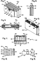
- Fig. 1 is an elevational view, with parts removed, of a prior art cathode plate, such as that used in the defibrillator cell disclosed in United States patent 4,830,940.
- Fig. 2 is a transverse sectional view taken about on line 2-2 in Fig. 1;
- Fig. 3 is a flagmentary sectional view of the defibrillator cell disclosed in United States patent 4,830,940.
- Fig. 4 is a perspective view of a cell stack insulating cover used in the cell of Fig. 3;
- Fig. 5 is an elevational view, with parts removed, of a twin plate cathode structure according to the present invention;
- Fig. 6 is a transverse sectional view of the twin plate cathode structureof the present invention taken about on line 6-6 in Fig. 5;
- Fig. 7 is a perspective view, with parts removed, of an anode, such as that included in the defibrillator cell of United States patent 4,830,940.
- Fig. 8 is a side elevational view of a cell stack assembly including the anode of Fig. 7 and a plurality of twin cathode plate structures of the present invention;
- Fig. 9 is a top plan view of the cell stack assembly of Fig. 8 in accordance with the present invention;
- Fig. 10 is a perspective view of a cell stack assembly of Fig. 8 in accordance with the present invention;
- Fig. 11 is an enlarged fragmentary sectional view of the cell stack assembly in accordance with the present invention;
- Fig. 12 is a plan view of a spacer used in the cell stack assembly of Fig. 11 in accordance with the present invention; and
- Fig. 13 is a plan view of a cell stack insulating cover used in the cell stack assembly in accordance with the present invention.
- The twin plate cathode structure of the present invention is for use in any multiplated alkali metal/solid cathode and alkali metal/oxyhalide cell assembly which includes a plurality of cathode plates operatively associated with anode means. Such alkali metal/solid cathode cells include, for example, metal oxide, fluorinated carbon and metal oxide bronze. The cell assembly using the twin plate cathode structures of the present invention may comprise a primary cell. For purposes of illustration only, and not limitation, the twin plate cathode structure of the present invention will be described herein in detail in a cell stack assembly of the type employed in an implantable cardiac defibrillator cell as disclosed in United States patent 4,830,940, which disclosure is hereby incorporated by reference. By using the twin plate cathode structure of the invention in the defibrillator cell stack assembly, assembly of the cell is made easier, thus simplifying manufacturing of the cell. The reliability of the cell is maintained, and even increased because the number of interconnections is reduced, which in turn reduces the number of weldments susceptible to failure during testing due to shock and vibration.
- Referring now to the drawings, Figures 1-3 show a prior art cathode plate and a plurality of such plates as assembled in a defibrillator cell such as that disclosed in United States patent 4,850,940.
Cathode plate 10 comprises a cathode conductor including abody portion 12 and alead portion 14. Theconductor body portion 12 is in the form of a thin sheet of metal screen comprised of any conductive metal or conductive material such as, for example, titanium or stainless steel.Lead portion 14 is in the form of a solid thin tab extending from one side ofscreen 12.Cathode plate 10 further comprises a body of cathode mixture including cathode active material and binder. The cathode active material is silver vanadium oxide, can include a binder such as Teflon and conductors such as graphite powder and acetylene black powder. - With reference to Figure 3, a total of eight
cathode plates 10a-10h are employed in the cell stack assembly. The two outer or end cathode plates,are slightly smaller in overall dimension to accommodate the shape of the casing of the defibrillator cell. All ofcathode plates 10a-10h are identical in construction tocathode plate 10 shown in Figure 1. The defibrillator cell, a portion of which is shown at 20, includes ahollow casing 21 having spaced apartside walls 22, 24, spaced apart end walls (not shown) and is closed at the top by a lid 26 welded in place in any known manner.Casing 21 is of metal such as stainless steel and being electrically conductive provides one terminal or contact for making electrical connection between the cell and its load. Lid 26 is also of a stainless steel. The other electrical terminal or contact is provided by a conductor or pin 28 extending from withincell 20 throughcasing 21, an in particular through lid 26. Pin 28 is insulted electrically from metal lid 26 by an insulator and seal structure (not shown).Anode structure 30 receivescathode plates 10a-10h therein thereby comprising the cell stack assembly, which is received incasing 21 ofcell 20. - A first
cell stack insulator 32 in the form of a thin elongated band or strip extends alongcasing sidewalls 22, 24 and bottom wall (not shown) and is located between the inner wall surfaces of the cell stack, particularly the outer surfaces ofanode portions 30. A second cell stack insulator (not shown) similar toinsulator 32 extends along casing end walls and bottom walls and is between the inner wall surfaces of the casing and the outer end and bottom surfaces of the cell stack. The insulators are provided to prevent internal electrical short circuits. - A cell
stack insulating cover 34 is located in the casing adjacent the upper surface of the cell stack and spaced in relation to lid 26, as viewed in Figure 3.Cover 34, shown in further detail in Figure 4, has aplaner body portion 36 including parallel side edges 38, 40, parallel end edges 42, 44 and curved or rounded corners so as to conform closely to the configuration defined by the inner surfaces of the casing sidewalls.Cover 34 is provided with a pair of flanges ortabs body 36.Tabs Body 36 is provided with a plurality of spaced apart, longitudinally disposedslots 50a-50h which are arranged in a row and extend transversely acrossbody 36.Slots 50a-50h are of a size, configuration and location to receivetabs 14a-14h, extending fromcathode plates 10a-10h, respectively. Thus, the cathode leads ortabs 14a-14h extend fromcathode plates 10a-10h in the stack belowcover 34 throughslots 50a-50h into the open region betweencover 34 and lid 26.Cover body 36 is provided with anopening 41 allowing flow of electrolyte therethrough into the region of the cell stack during the filling procedure. - Each of cathode leads 14a-14h is bent or formed into approximate right angles as shown in Figure 3. Each leg extends in the same direction with the inner surface of one lead contacting and secured, such as by welding in two places, to the outer surface of the neighboring lead. Lead 14b is bent into a formation including a right angle portion like the other leads and then the outer end is formed into a return bend.
Lead 14a is of considerably greater length than the other leads and is bent into a right angle extending in the opposite direction and overlying the remaining leads 14b-14h.Lead 14a is connected to lead 14b as shown in Figure 3. The remaining end portion oflead 14a extends transversely and is welded in two places to lead 14h. An intermediate lead 52 in the form of a ribbon or strip is fixed at one end to lead 14a and extends longitudinally relative tobody 34 and the casing and is provided for connection to terminal pin 28 through the insulator and seal structure, generally shown at 54. During manufacture, approximately 16 welds are necessary to connect the cathode leads 14a-14h. Further, eachcathode lead 14a-14b is individually fed throughslots 50a-50b incover 34 prior to bending and welding. - The procedure described above to assemble the leads as shown in Figure 3 is very time consuming, costly and may require numerous spot welds. Further, if the leads are not cut correctly an upward slope may develop from lead 14h to lead 14a such that the electrodes may not seat properly, subsequently interfering with closing the cell case. Additionally, the greater the number of weldments, the more susceptible the cell may be to failure during testing due to vibration and shock. These problems are essentially avoided by using the twin plate cathode structure of the present invention in the cell stack assembly. In particular, a cell stack assembly comprising the twin cathode plate structure of the present invention can be substituted for the prior art cell stack assembly used in the defibrillator cell, as shown in Figure 3. The remaining components and methods of assembly of the defibrillator cell as shown in Figure 3, will remain the same. For a more detailed description, refer to the discloure of United States patent 4,830,940, which disclosure is hereby incorporated by reference. It is understood, however, that the twin plate cathode structures of the present invention may be used in any alkali metal/solid cathode and alkali metal/oxyhalide cell systems which includes a plurality of cathode plates operatively associated with anode means.
- With reference to Figures 5 and 6, there is illustrated the twin plate cathode structure of the present invention. The twin cathode plate structure, generally indicated 53 includes two
cathode plates Cathode plates cathode bodies current collector portions cathode bodies current collector portions current collector portions screen 58a to one side ofscreen 58b thereby connectingscreen 58a to screen 58b.Cathode bodies Cathode plate 53 is made by first preparing a cathode mix of active material and binder and then drying the prepared mixture at a particular temperature for a short time prior to use. By way of example the cathode mix comprises 94 weight percent AgxV₂Oy, three weight percent Teflon powder, two weight percent graphite powder and one weight percent carbon. ,This ratio of dry materials is thoroughly mixed in a ball mill and dried overnight at 140°C for use. The twin plate cathode structure is then formed by placing half the approximate weight of the foregoing cathode mixture in a pressing fixture placing the cathode screen on the top of the.mixture, adding the remaining cathode mix. The top half of the pressing fixture is inserted and pressure applied for example, 36,000-38,000 lbs. per square inch for about 45 seconds. Alternatively, the entire mixture can be placed on the screen in a manner allowing about half to pass through into the lower portion of the fixture. Two such plates are formed in the one of the manners and previously described connected by conductor means 60, which is welded to each of the plates. The cathode screens and,conductor means may also be fabricated out of a sheet of metal as a single unit. A more detailed description of preparing the cathode plates is described in U.S. patent 4,830,940, which disclosure is hereby incorporated by reference. - After preparation of the mixture and pressing onto cathode
current collector portions separator material 64a, 64b, for example, polypropylene or polyethylene. By way of example,separator material 64a, 64b may comprise a single layer of commercially available Celgard non-woven polypropylene separator material which is pressed on the cathode plates and heat sealed around the edges. All other twin plate cathode structures used in the cell stack assembly are identical in construction to the twin plate cathode structure shown in Figure 5. The dimensions of the cell stack assembly including the plurality of twin plate cathode structures of the present invention will vary based on cell type. The twin plate cathode structure shown in Fig. 5 is for use in a cell stack assembly including a plurality of such structures, operatively associated with anode means. Anode means, shown generally at 31 in Figure 8, will be described in detail hereinafter. - With reference to Figure 7 there is illustrated anode means generally indicated 31, which in conjunction with a plurality of twin plate cathode structures of the present invention form the cell stack assembly. Anode means 31 comprises a continuous elongated element or structure of alkali metal, preferably lithium or lithium alloy, enclosed within separator material and folded into a plurality of sections which are interposed between ,the twin plate cathode structures. Referring now in detail to Figure 7, anode means 31 comprises an elongated continuous ribbon like
anode conductor element 64 in the form of a thin metal screen, for example nickel.Conductor 64 includes at least one terminal or contact tab extending therefrom. In the anode structure for use in the cell stack assembly of the defibrillator cell there are twotabs conductor 64.Anode 31 further comprises a pair of elongated ribbon-like lithium elements 74 pressed together against opposite sides ofconductor element 64 to form an anode structure.Lithium elements 74 are substantially equal in width and length toconductor element 64. The resulting anode structure is a sandwiched-like construction withconductor 64 betweenlithium elements 74. Anode means 31 further comprises aseparator material 76 encapsulating the anode structure. The anodestructure comprising conductor 64 andlithium elements 74 is enclosed or wrapped in an envelope of separator material, for example polypropylene or polyetheylene. The resultinganode structure 31 is folded at spaced intervals along the length thereof to form a serpentine-like structure which receives between the folds thereof the plurality of twin plate cathode structures to form the cell stack assembly. In particular, anode means 31 is folded at theintervals anode 31, which will be described hereinafter, to form the cell stack assembly which is received in the casing of the cell such as that shown and described in Figure 3. - With reference to Figure 12, there is shown a spacer lead generally indicated 106, having parallel side edges 108, 110, and end
edges 112, 114 joining side edges 108, 110 and extending perpendicular thereto. Side edge 114 is formed to include a plurality of curved orrounded portions 116.Spacer 106 is also provided with a plurality of spaced apart, longitudinally disposedslots 118a - 118f which are arranged in a row extending transversely acrossspacer 106.Slots 118a - 118f are of a size and configuration to receivetabs 60 which extend from twinplate cathode structures 53, which will become more apparent during the ensuing description of the method of assembling the cell stack assembly.Spacer lead 106 can be made of Tefzel or Halar material in the illustrative cell stack assembly of the present invention. With reference to Figure 13, there is illutrated an insulating cover generally shown at 86, which is similar to insulatingcover 34 in Figure 4.Cover 86 has aplanar body portion 88 including parallel side edges 90, 92 and parallel end edges 94, 96.Cover 34 is provided with a pair of flanges ortabs 100, 102 extending from side edges 90, 92 and disposed at about right angles tobody 88.Tabs 100, 102 are used to insulate the anode leads from the cathode plates.Body 88 is provided with a substantiallyrectangular opening 104 for receivingtabs 60 of twinplate cathode structures 53 therethrough.Insulator 86 is provided to prevent internal electrical short circuits and can be made of Tefzel or Halar material in the illustrative cell stack, assembly of the present invention. - The cell stack assembly generally designated 120 in Figure 8-11 is assembled using a plurality of cathode structures of the present invention interposed between anode means 31 in the following manner.
Anode 31 is folded into a serpentine like assembly as shown in Figure 7 using a conventional pressing apparatus. Twinplate cathode structure 53 shown in Figure 5 is shaped by bending such thatlead portion 60 is rounded at the upper portion thereof as shown at 61 in Figure 8 andplates anode 31. Cellstack insulating cover 86 is then positioned in place with each of the three leads 60 extending throughopening 104.Spacer 106, (Fig. 12), is then positioned in place such that each leg portion 63 (Fig. 11) is positioned through thecorresponding slot 118a-118f. Thereafter,transverse bar 62 is welded to each of theleads 60 in two places laterally of the bar such thatbar 62 horizontally extends across each of leads 60 to thereby facilitate connection between the three twin plate cathode structures. Thecell stack assembly 120 is then inserted into the casing of a cell such as that shown in Figure 3, in the manner disclosed in U.S. Patent 4,830,940, which is hereby incorporated by reference. - It is apparent that the present invention accomplishes its intended objects. By using the twin plate cathode structure of the present invention in the cell stack assembly, the assembly of the cell is made easier, the alignment of the cathode plates is done automatically and the number of interconnections is reduced, thus simplifying the assembly and welding operation. The reduced weldments also may increase the reliability of the cell by reducing the number of connections susceptible to failure due to vibration and shock. It will be understood that the foregoing description and illustration is by way of example only and that any such modifications and/or changes as may suggest themselves to those skilled in the art are intended to fall within the scope of the present invention as defined by the appended claims.
Claims (22)
- A twin plate cathode structure for use in an alkali metal/solid cathode and alkali metal/oxyhalide cell assembly including a plurality of cathode plates comprising:
at least two cathode bodies each comprising cathode active material portions; and
an electrode including two cathode current collector portions operatively associated with corresponding ones of the cathode bodies and an intermediate conductor means joining the two collector for making electrical connection to the cathode structure. - The twin plate cathode structure of claim 1, wherein said collector portions are embedded in the corresponding cathode bodies.
- The twin plate cathode structure of Claim 1 or Claim 2, wherein said cell is a primary cell.
- The twin plate cathode structure of any preceding claim, further comprising a separator material encasing the cathode bodies and associated electrode portions.
- The twin plate cathode structure of any preceding claim, wherein said solid cathode material is selected from the group consisting of a metal oxide, metal oxide bronze or fluorinated carbon.
- The twin plate cathode structure of claim 5, wherein said cathode material is metal oxide bronze.
- The twin plate cathode structure of claim 6 when said metal oxide bronze is silver vanadium oxide AgxV₂Oy where x is in the range from about 0.5 to about 2.0 and y is in the range from about 4.5 to about 6.0.
- The twin plate cathode structure of claim 7, wherein said metal oxide bronze is silver vanadium oxide AgxV₂Oy wherein x is in the range from about 0.95 to about 1.1 and y is in the range from about 5.0 to about 6.0.
- The twin plate cathode structure of any preceding claim, wherein said cathode active material is pressed onto said collector portions in the form of a pellet.
- The twin plate cathode structure of claim 9, wherein said cathode active material further comprises a binder and conductor materials.
- The twin plate cathode structure of Claim 1, in combination with anode means comprising a continuous elongated alkali metal element enclosed within a separator material and folded into a plurality of sections interposed between said cathode structures.
- The twin plate cathode structure of claim 11, wherein said alkali metal is lithium.
- The twin plate cathode structure of claim 12, wherein said lithium anode means comprises:
an elongated ribbon-like anode conductor element;
a pair of elongated ribbon-like lithium elements pressed together against opposite sides of said conductor element to form an anode structure;
separator material encapsulating said anode structure; and
said anode structure being folded at spaced intervals along the length thereof to form a serpentine-like structure to receive between the folds thereof a plurality of said cathode structures. - The twin plate cathode structure of Claim 11 or Claim 12, wherein said lithium anode means further includes at least one terminal tab extending therefrom.
- The twin plate cathode structure of Claim 1, wherein said cell is an alkali metal non-aqueous silver vanadium oxide cell.
- The twin plate cathode structure of Claim 1, wherein said cathode is oxyhalide.
- The twin plate cathode structure of any preceding claim, in combination with at least one further said cathode structure arranged to form a cathode cell assembly and means operatively connected to said intermediate conductor means of each of said cathode structures for making electrical connection thereto.
- A cell stack assembly for use in an alkali metal/solid cathode and alkali metal/oxyhalide cell, comprising:
a plurality of twin plate cathode structures according to any of Claims 1 to 10, 15, 16 or 17, and anode means operatively associated with the cathode plates of said structures. - The cell stack assembly of Claim 18, said anode means comprising a continuous elongated alkali metal element enclosed within a separator material and folded into a plurality of sections interposed between said twin plate cathode structure s.
- The cell stack assembly of claim 19, wherein said assembly further comprises a spacer positioned adjacent said intermediate conductor means, said spacer comprising:
a body portion having parallel side edges and end edges joining said side edges and extending perpendicular thereto; and
a plurality of spaced apart longitudinally disposed slots arranged in a row extending transversely across said body portion, said slots positioned adjacent said intermediate conductor means in said cell stack assembly. - The cell stack assembly of claim 19, wherein said assembly further comprises an insulating cover for preventing internal electrical short circuits, said cover comprising:
a planar body portion including parallel side edges and parallel end eges;
a pair of flanges extending from said side edges and disposed at about right angles to said body portion; and
a substantially rectangular opening on said body portion for receiving said intermediate conductor means therethrough. - A method of forming a cell stack assembly including a plurality of twin plate cathode structures operatively associated with anode means, said cell stack assembly for use in an alkali metal/solid cathode and alkali metal/oxyhalide cell, comprising:
folding said anode means into a serpentine-like assembly using a conventional pressing apparatus;
shaping each of said twinplate cathode structures by bending such that the lead portions extending therefrom are rounded at the upper end thereof and the twin plates are juxtaposed in a facing, spaced parallel relation to one another;
inserting said shaped twin plate cathode structures between the folds of said anode means such that each fold has a cathode structure therebetween;
positioning a spacer in place;
positioning an insulating cover in place; and
welding a transverse bar to each of the leads in at least two places laterally of the bar such that the bar extends longitudinally across the leads.
Applications Claiming Priority (2)
| Application Number | Priority Date | Filing Date | Title |
|---|---|---|---|
| US757251 | 1985-07-22 | ||
| US75725191A | 1991-09-10 | 1991-09-10 |
Publications (2)
| Publication Number | Publication Date |
|---|---|
| EP0532313A1 true EP0532313A1 (en) | 1993-03-17 |
| EP0532313B1 EP0532313B1 (en) | 1997-02-05 |
Family
ID=25047054
Family Applications (1)
| Application Number | Title | Priority Date | Filing Date |
|---|---|---|---|
| EP92308220A Expired - Lifetime EP0532313B1 (en) | 1991-09-10 | 1992-09-10 | Twin plate cathode assembly for multiplate electrochemical cells |
Country Status (5)
| Country | Link |
|---|---|
| US (1) | US5716735A (en) |
| EP (1) | EP0532313B1 (en) |
| AT (1) | ATE148806T1 (en) |
| AU (1) | AU661859B2 (en) |
| DE (1) | DE69217306T2 (en) |
Cited By (5)
| Publication number | Priority date | Publication date | Assignee | Title |
|---|---|---|---|---|
| FR2748606A1 (en) * | 1996-05-07 | 1997-11-14 | Accumulateurs Fixes | Connection of electrode plates to terminal of electrochemical generator e.g. used in electric vehicle |
| EP1143544A2 (en) * | 2000-04-05 | 2001-10-10 | Wilson Greatbatch Ltd. | Application of Gamma-SVO and mixture of Gamma-SVO/ Epsilon-SVO in high rate electrochemical lithium cells containing SVO/CFx/SVO sandwich cathodes |
| EP1156544A2 (en) * | 2000-05-16 | 2001-11-21 | Wilson Greatbatch Ltd. | Efficient cell stack for cells with double screen sandwich cathodes |
| EP1233465A1 (en) * | 2001-02-15 | 2002-08-21 | Wilson Greatbatch Ltd. | Current collector having non-symmetric grid pattern converging at a common focal point |
| US7056358B2 (en) | 2000-04-05 | 2006-06-06 | Wilson Greatbatch Technologies, Inc. | Method for using high rate lithium electrochemical cell containing SVO/CFchi/SVo sandwich cathodes having γ-SVO and mixture of γ-SVO/ε-SVO |
Families Citing this family (13)
| Publication number | Priority date | Publication date | Assignee | Title |
|---|---|---|---|---|
| US6287721B1 (en) | 1998-09-24 | 2001-09-11 | Thomas & Betts International, Inc. | Process for manufacturing electrochemical cells |
| US7432001B1 (en) | 2003-12-09 | 2008-10-07 | Greatbatch Ltd. | Prevention of lithium deposition in nonaqueous electrolyte cells by electrolyte-to-cathode weight ratio |
| US7482093B1 (en) | 2003-12-09 | 2009-01-27 | Greatbatch Ltd. | Insulator design to prevent lithium cluster bridging |
| US20070281207A1 (en) * | 2003-12-09 | 2007-12-06 | Takeuchi Esther S | Prevention of lithium deposition in nonaqueous electrolyte cells by matching device usage to cell capacity |
| US8399116B2 (en) | 2007-12-25 | 2013-03-19 | Byd Co. Ltd. | Optimized dimensional relationships for an electrochemical cell having a coiled core |
| US9899655B2 (en) * | 2012-09-14 | 2018-02-20 | Greatbatch Ltd. | Electrochemical current collector screen designs utilizing ultrasonic welding |
| US11788500B2 (en) * | 2016-02-11 | 2023-10-17 | The Noco Company | Battery device for a battery jump starting device |
| US11458851B2 (en) | 2014-07-03 | 2022-10-04 | The Noco Company | Jump starting apparatus |
| US9007015B1 (en) | 2014-07-03 | 2015-04-14 | The Noco Company | Portable vehicle battery jump start apparatus with safety protection |
| US9620764B2 (en) | 2015-01-05 | 2017-04-11 | Johnson Controls Technology Company | Battery module cooling fins and footings system and method |
| USD847746S1 (en) | 2016-10-07 | 2019-05-07 | Daramic, Llc | Battery separator |
| US11769906B2 (en) * | 2017-09-14 | 2023-09-26 | Ampcera Inc. | Systems and methods for selectively extracting alkaline metals from metal-rich solutions using solid state ionic conductive electrolyte membrane |
| EP3707368A4 (en) | 2017-12-14 | 2021-09-29 | The Noco Company | Portable vehicle battery jump starter with air pump |
Citations (3)
| Publication number | Priority date | Publication date | Assignee | Title |
|---|---|---|---|---|
| US4209576A (en) * | 1978-02-28 | 1980-06-24 | Saft-Societe Des Accumulateurs Fixes Et De Traction | Assembly of a group of electrodes and a terminal of a storage |
| GB2129196A (en) * | 1982-10-29 | 1984-05-10 | Chloride Group Plc | Bipolar electrode pairs for electric storage batteries |
| US4830940A (en) * | 1986-01-14 | 1989-05-16 | Wilson Greatbatch Ltd. | Non-agueous lithium battery |
Family Cites Families (1)
| Publication number | Priority date | Publication date | Assignee | Title |
|---|---|---|---|---|
| US5250373A (en) * | 1991-09-10 | 1993-10-05 | Wilson Greatbatch Ltd. | Internal electrode and assembly method for electrochemical cells |
-
1992
- 1992-09-09 AU AU22826/92A patent/AU661859B2/en not_active Ceased
- 1992-09-10 DE DE69217306T patent/DE69217306T2/en not_active Expired - Lifetime
- 1992-09-10 AT AT92308220T patent/ATE148806T1/en not_active IP Right Cessation
- 1992-09-10 EP EP92308220A patent/EP0532313B1/en not_active Expired - Lifetime
-
1996
- 1996-07-29 US US08/681,823 patent/US5716735A/en not_active Expired - Lifetime
Patent Citations (3)
| Publication number | Priority date | Publication date | Assignee | Title |
|---|---|---|---|---|
| US4209576A (en) * | 1978-02-28 | 1980-06-24 | Saft-Societe Des Accumulateurs Fixes Et De Traction | Assembly of a group of electrodes and a terminal of a storage |
| GB2129196A (en) * | 1982-10-29 | 1984-05-10 | Chloride Group Plc | Bipolar electrode pairs for electric storage batteries |
| US4830940A (en) * | 1986-01-14 | 1989-05-16 | Wilson Greatbatch Ltd. | Non-agueous lithium battery |
Cited By (10)
| Publication number | Priority date | Publication date | Assignee | Title |
|---|---|---|---|---|
| FR2748606A1 (en) * | 1996-05-07 | 1997-11-14 | Accumulateurs Fixes | Connection of electrode plates to terminal of electrochemical generator e.g. used in electric vehicle |
| EP1143544A2 (en) * | 2000-04-05 | 2001-10-10 | Wilson Greatbatch Ltd. | Application of Gamma-SVO and mixture of Gamma-SVO/ Epsilon-SVO in high rate electrochemical lithium cells containing SVO/CFx/SVO sandwich cathodes |
| EP1143544A3 (en) * | 2000-04-05 | 2002-11-13 | Wilson Greatbatch Ltd. | Application of Gamma-SVO and mixture of Gamma-SVO/ Epsilon-SVO in high rate electrochemical lithium cells containing SVO/CFx/SVO sandwich cathodes |
| US6607861B2 (en) | 2000-04-05 | 2003-08-19 | Wilson Greatbatch Ltd. | Application of γ-SVO and mixture of γ-SVO/ε-SVO in high rate electrochemical lithium cells containing SVO/CFx/SVO sandwich cathodes |
| US7056358B2 (en) | 2000-04-05 | 2006-06-06 | Wilson Greatbatch Technologies, Inc. | Method for using high rate lithium electrochemical cell containing SVO/CFchi/SVo sandwich cathodes having γ-SVO and mixture of γ-SVO/ε-SVO |
| EP1156544A2 (en) * | 2000-05-16 | 2001-11-21 | Wilson Greatbatch Ltd. | Efficient cell stack for cells with double screen sandwich cathodes |
| EP1156544A3 (en) * | 2000-05-16 | 2003-05-07 | Wilson Greatbatch Ltd. | Efficient cell stack for cells with double screen sandwich cathodes |
| US6645670B2 (en) | 2000-05-16 | 2003-11-11 | Wilson Greatbatch Ltd. | Efficient cell stack for cells with double current collectors sandwich cathodes |
| EP1233465A1 (en) * | 2001-02-15 | 2002-08-21 | Wilson Greatbatch Ltd. | Current collector having non-symmetric grid pattern converging at a common focal point |
| US6893777B2 (en) * | 2001-02-15 | 2005-05-17 | Wilson Greatbatch Ltd. | Current collector having non-symmetric grid pattern converging at a common focal point |
Also Published As
| Publication number | Publication date |
|---|---|
| AU661859B2 (en) | 1995-08-10 |
| AU2282692A (en) | 1993-03-11 |
| EP0532313B1 (en) | 1997-02-05 |
| DE69217306T2 (en) | 1997-08-07 |
| ATE148806T1 (en) | 1997-02-15 |
| DE69217306D1 (en) | 1997-03-20 |
| US5716735A (en) | 1998-02-10 |
Similar Documents
| Publication | Publication Date | Title |
|---|---|---|
| EP0532313B1 (en) | Twin plate cathode assembly for multiplate electrochemical cells | |
| EP0237146B1 (en) | Non-aqueous alkali metal cell | |
| US6893772B2 (en) | Current collector for lithium electrode | |
| US4964877A (en) | Non-aqueous lithium battery | |
| US5434017A (en) | Isolated connection for an electrochemical cell | |
| US5744261A (en) | Insulating inclosure for lithium batteries | |
| US5549717A (en) | Method of making prismatic cell | |
| US5312458A (en) | Internal electrode and assembly method for electrochemical cells | |
| US7718312B2 (en) | Battery | |
| US6120563A (en) | Method for providing a flat-folded, multi-plate electrode assembly | |
| US5525441A (en) | Folded electrode configuration for galvanic cells | |
| JPS61264678A (en) | Hybrid electrode | |
| CA1215741A (en) | Grids for electric storage batteries | |
| US6425928B2 (en) | Method for providing a bi-directionally wound cell stack for enhanced battery performance | |
| EP0798794A1 (en) | A cell which secures the reliability of a protective circuit | |
| EP0655793A2 (en) | High-reliability electrochemical cell and electrode assembly therefor | |
| US7592097B2 (en) | Electrochemical cell designs with anode plates and connections which facilitate heat dissipation | |
| US6159253A (en) | Thermally formed tab slots in a separator for a spirally-wound electrochemical cell | |
| US6569558B1 (en) | Prismatic high rate cell | |
| US20020150817A1 (en) | Low profile battery termination | |
| US6593028B1 (en) | Separator envelope for swelling in electrochemical cells | |
| US4372038A (en) | Method for assembling an electrochemical cell | |
| KR900004585Y1 (en) | Electrode assembly | |
| JP2567647B2 (en) | Square sealed battery | |
| JPH02201867A (en) | Sealed square alkaline storage battery and manufacture thereof |
Legal Events
| Date | Code | Title | Description |
|---|---|---|---|
| PUAI | Public reference made under article 153(3) epc to a published international application that has entered the european phase |
Free format text: ORIGINAL CODE: 0009012 |
|
| AK | Designated contracting states |
Kind code of ref document: A1 Designated state(s): AT BE CH DE DK ES FR GB GR IT LI NL PT SE |
|
| 17P | Request for examination filed |
Effective date: 19930915 |
|
| 17Q | First examination report despatched |
Effective date: 19941012 |
|
| GRAG | Despatch of communication of intention to grant |
Free format text: ORIGINAL CODE: EPIDOS AGRA |
|
| GRAH | Despatch of communication of intention to grant a patent |
Free format text: ORIGINAL CODE: EPIDOS IGRA |
|
| GRAH | Despatch of communication of intention to grant a patent |
Free format text: ORIGINAL CODE: EPIDOS IGRA |
|
| GRAA | (expected) grant |
Free format text: ORIGINAL CODE: 0009210 |
|
| AK | Designated contracting states |
Kind code of ref document: B1 Designated state(s): AT BE CH DE DK ES FR GB GR IT LI NL PT SE |
|
| PG25 | Lapsed in a contracting state [announced via postgrant information from national office to epo] |
Ref country code: LI Effective date: 19970205 Ref country code: GR Free format text: LAPSE BECAUSE OF FAILURE TO SUBMIT A TRANSLATION OF THE DESCRIPTION OR TO PAY THE FEE WITHIN THE PRESCRIBED TIME-LIMIT Effective date: 19970205 Ref country code: ES Free format text: THE PATENT HAS BEEN ANNULLED BY A DECISION OF A NATIONAL AUTHORITY Effective date: 19970205 Ref country code: DK Effective date: 19970205 Ref country code: CH Effective date: 19970205 Ref country code: BE Effective date: 19970205 Ref country code: AT Effective date: 19970205 |
|
| REF | Corresponds to: |
Ref document number: 148806 Country of ref document: AT Date of ref document: 19970215 Kind code of ref document: T |
|
| REG | Reference to a national code |
Ref country code: CH Ref legal event code: EP |
|
| ITF | It: translation for a ep patent filed |
Owner name: 0403;12MIFING. A. GIAMBROCONO & C. S.R.L |
|
| REF | Corresponds to: |
Ref document number: 69217306 Country of ref document: DE Date of ref document: 19970320 |
|
| ET | Fr: translation filed | ||
| PG25 | Lapsed in a contracting state [announced via postgrant information from national office to epo] |
Ref country code: PT Effective date: 19970505 |
|
| REG | Reference to a national code |
Ref country code: CH Ref legal event code: PL |
|
| PLBE | No opposition filed within time limit |
Free format text: ORIGINAL CODE: 0009261 |
|
| STAA | Information on the status of an ep patent application or granted ep patent |
Free format text: STATUS: NO OPPOSITION FILED WITHIN TIME LIMIT |
|
| 26N | No opposition filed | ||
| REG | Reference to a national code |
Ref country code: GB Ref legal event code: IF02 |
|
| PGFP | Annual fee paid to national office [announced via postgrant information from national office to epo] |
Ref country code: NL Payment date: 20040923 Year of fee payment: 13 |
|
| PGFP | Annual fee paid to national office [announced via postgrant information from national office to epo] |
Ref country code: GB Payment date: 20050902 Year of fee payment: 14 |
|
| PGFP | Annual fee paid to national office [announced via postgrant information from national office to epo] |
Ref country code: SE Payment date: 20050909 Year of fee payment: 14 |
|
| PG25 | Lapsed in a contracting state [announced via postgrant information from national office to epo] |
Ref country code: IT Free format text: LAPSE BECAUSE OF NON-PAYMENT OF DUE FEES;WARNING: LAPSES OF ITALIAN PATENTS WITH EFFECTIVE DATE BEFORE 2007 MAY HAVE OCCURRED AT ANY TIME BEFORE 2007. THE CORRECT EFFECTIVE DATE MAY BE DIFFERENT FROM THE ONE RECORDED. Effective date: 20050910 |
|
| PG25 | Lapsed in a contracting state [announced via postgrant information from national office to epo] |
Ref country code: NL Free format text: LAPSE BECAUSE OF NON-PAYMENT OF DUE FEES Effective date: 20060401 |
|
| NLV4 | Nl: lapsed or anulled due to non-payment of the annual fee |
Effective date: 20060401 |
|
| PG25 | Lapsed in a contracting state [announced via postgrant information from national office to epo] |
Ref country code: SE Free format text: LAPSE BECAUSE OF NON-PAYMENT OF DUE FEES Effective date: 20060911 |
|
| EUG | Se: european patent has lapsed | ||
| GBPC | Gb: european patent ceased through non-payment of renewal fee |
Effective date: 20060910 |
|
| PG25 | Lapsed in a contracting state [announced via postgrant information from national office to epo] |
Ref country code: GB Free format text: LAPSE BECAUSE OF NON-PAYMENT OF DUE FEES Effective date: 20060910 |
|
| PGFP | Annual fee paid to national office [announced via postgrant information from national office to epo] |
Ref country code: DE Payment date: 20100929 Year of fee payment: 19 |
|
| PGFP | Annual fee paid to national office [announced via postgrant information from national office to epo] |
Ref country code: FR Payment date: 20111005 Year of fee payment: 20 |
|
| REG | Reference to a national code |
Ref country code: DE Ref legal event code: R071 Ref document number: 69217306 Country of ref document: DE |
|
| REG | Reference to a national code |
Ref country code: DE Ref legal event code: R071 Ref document number: 69217306 Country of ref document: DE |
|
| PG25 | Lapsed in a contracting state [announced via postgrant information from national office to epo] |
Ref country code: DE Free format text: LAPSE BECAUSE OF EXPIRATION OF PROTECTION Effective date: 20120911 |