EP0532109A1 - Double lumen catheter - Google Patents
Double lumen catheter Download PDFInfo
- Publication number
- EP0532109A1 EP0532109A1 EP92202725A EP92202725A EP0532109A1 EP 0532109 A1 EP0532109 A1 EP 0532109A1 EP 92202725 A EP92202725 A EP 92202725A EP 92202725 A EP92202725 A EP 92202725A EP 0532109 A1 EP0532109 A1 EP 0532109A1
- Authority
- EP
- European Patent Office
- Prior art keywords
- channel
- catheter
- basic material
- core wires
- guide wire
- Prior art date
- Legal status (The legal status is an assumption and is not a legal conclusion. Google has not performed a legal analysis and makes no representation as to the accuracy of the status listed.)
- Granted
Links
Images

Classifications
-
- A—HUMAN NECESSITIES
- A61—MEDICAL OR VETERINARY SCIENCE; HYGIENE
- A61M—DEVICES FOR INTRODUCING MEDIA INTO, OR ONTO, THE BODY; DEVICES FOR TRANSDUCING BODY MEDIA OR FOR TAKING MEDIA FROM THE BODY; DEVICES FOR PRODUCING OR ENDING SLEEP OR STUPOR
- A61M25/00—Catheters; Hollow probes
- A61M25/0009—Making of catheters or other medical or surgical tubes
-
- A—HUMAN NECESSITIES
- A61—MEDICAL OR VETERINARY SCIENCE; HYGIENE
- A61M—DEVICES FOR INTRODUCING MEDIA INTO, OR ONTO, THE BODY; DEVICES FOR TRANSDUCING BODY MEDIA OR FOR TAKING MEDIA FROM THE BODY; DEVICES FOR PRODUCING OR ENDING SLEEP OR STUPOR
- A61M25/00—Catheters; Hollow probes
- A61M25/0021—Catheters; Hollow probes characterised by the form of the tubing
- A61M25/0023—Catheters; Hollow probes characterised by the form of the tubing by the form of the lumen, e.g. cross-section, variable diameter
- A61M25/0026—Multi-lumen catheters with stationary elements
- A61M2025/0037—Multi-lumen catheters with stationary elements characterized by lumina being arranged side-by-side
-
- G—PHYSICS
- G02—OPTICS
- G02B—OPTICAL ELEMENTS, SYSTEMS OR APPARATUS
- G02B6/00—Light guides; Structural details of arrangements comprising light guides and other optical elements, e.g. couplings
- G02B6/24—Coupling light guides
- G02B6/36—Mechanical coupling means
- G02B6/38—Mechanical coupling means having fibre to fibre mating means
- G02B6/3807—Dismountable connectors, i.e. comprising plugs
- G02B6/3873—Connectors using guide surfaces for aligning ferrule ends, e.g. tubes, sleeves, V-grooves, rods, pins, balls
- G02B6/3874—Connectors using guide surfaces for aligning ferrule ends, e.g. tubes, sleeves, V-grooves, rods, pins, balls using tubes, sleeves to align ferrules
- G02B6/3878—Connectors using guide surfaces for aligning ferrule ends, e.g. tubes, sleeves, V-grooves, rods, pins, balls using tubes, sleeves to align ferrules comprising a plurality of ferrules, branching and break-out means
Definitions
- the invention relates to a method for manufacturing a double-lumen catheter.
- this method comprises of providing a piece of tube-like catheter basic material with two parallel, mutually separated lengthwise channels, providing two pieces of tube-like catheter basic material each having one lengthwise channel providing two core wires, each with a first portion closely fitting in the channels of the two-channel basic material, a second portion with a cross section substantially corresponding with the external cross section of the single-channel basic material and a transitional portion therebetween, the shape of the section of which gradually transposes from that of the first portion to that of the lengthwise channel of the single-channel basic material, inserting the first portion of each core wire into each channel in the end part of the two-channel basic material, providing a mould with a Y-shaped mould cavity, which is provided with fixing means for enclosed receiving of the end part of the two-channel basic material close to the foot of the Y and with fixing means for enclosed receiving of the second portion of the core wires close to the ends of the arms of the Y, receiving into the mould the end
- the double-lumen catheter according to the invention is particularly intended for angioscopic uses.
- the two-channel or double-lumen part of the catheter is inserted into a patient.
- the one channel is used for a guide wire, while an optic fibre bundle, in particular a fibre bundle of an endoscope, is pushed through the other channel.
- the guide wire and the fibre bundle can be fed in and manipulated separately of one another via the single-lumen parts of the catheter.
- Achieved with the method according to the invention is that the transition from the single-channel catheter part to the fork piece and from the fork piece to the two-channel catheter part is uniform, without internally protruding edges which could make the introduction of the guide wire and/or fibre bundle difficult.
- the step of claim 3 is preferably applied.
- the core wires When the core wires are pulled out of the formed fork piece, they deform elastically when following the channel formed in the fork piece by the first portion of the core wire, so that the core wires can be taken out easily.
- a suitable embodiment enabling repeated use is therein characterized in claim 4.
- the invention likewise relates to and provides a double-lumen catheter manufactured according to any of the above described embodiments of the method according to the invention.
- the invention likewise relates to and provides an assembly of such a catheter and a guide wire wherein the guide wire is curved close to its leading end.
- the guide wire By rotating the guide wire inserted into the catheter about its longitudinal axis the leading end of the catheter will swivel round, whereby the end of the endoscope fibre bundle can be oriented in a desired direction.
- a favourable embodiment is herein characterized in claim 8.
- a guide catheter forming part of an assembly as characterized in claim 9.
- the person administering treatment can see that the extremity of the double-lumen catheter is on the point of leaving the guide catheter.
- Fig. 1 shows a perspective view of a piece of two-channel catheter basic material which is used in the method according to the present invention.
- Fig. 2 shows on a smaller scale a second step of the embodiment of the method.
- Fig. 3 shows a third step of the embodiment of the method.
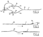
- Fig. 4 shows a simplified top view of a double-lumen catheter manufactured with the method according to the invention.
- Fig. 6 shows schematically an end part of a double-lumen catheter manufactured with the method according to the invention, in order to elucidate its use.
- the starting material in applying the method is a piece of tube-like catheter basic material 1, such as that shown in fig. 1, with two parallel channels 3 and 4 mutually separated by a dividing wall 2. These channels have a D-shaped section, as can be seen in fig. 1.
- core wires 11, 12 are inserted into the end parts of the channels 3, 4 as shown in fig. 3.
- Each of these core wires 11, 12 comprises a first portion 13 with a diameter which is slightly, for example 0.1 mm, larger than the diameter of the channels 3, 4 so that these first portions 13 of the core wires 11, 12 slightly expand the basic material when inserted.
- Each core wire 11, 12 further comprises a second portion 14 having a diameter substantially equal to a piece of single-channel basic material to be described hereinafter which will form a continuous connection with the relevant lengthwise channel of the two-channel basic material 1.
- first portion 13 Situated between the first portion 13 and the second portion 14 is a transitional portion the sectional shape of which gradually transposes from that of the first portion to that of the lengthwise channel of that single-channel basic material.
- Each core wire 11, 12 moreover has an end part 15 which is intended for the fixing in a mould.
- This mould 17 is shown schematically in fig. 3. It can be seen that a Y-shaped mould cavity 18 has been recessed into the mould 17. The end part of the basic material 1 is received close to the stem of the Y with the first portions of the core wires 11, 12 inserted into the channels 3, 4. The fixing parts 15 of the core wires 11, 12 are clamped in the extensions of the arms of the Y. As can be seen clearly from fig. 3, the mould cavity 18 defines a fork piece as designated in fig. 4 by 22 wherein a channel connecting precisely onto the end parts of the channels 3, 4 is recessed by the first portions 13 of the core wires 11, 12, which channel transposes into a wider portion which is defined by the second portions 14 and into which pieces of single-channel catheter basic material 23, 24 (fig.
- the channels of the single-channel parts 23, 24 connect precisely and without abrupt transition onto the channels in the fork piece 22 recessed by the first portions 13 of the core wires 11, 12.
- the mould 17 is further provided with a feed channel 19 onto which a nozzle 20 of an injection moulding machine 20 can connect.
- a suitable plastic is injected via this nozzle 20 into the mould cavity 18. After curing, this plastic forms the fork piece 22.
- the end parts 13 of the core wires 11, 12 are preferably of a flexible material, preferably spring steel.
- the end wires can hereby easily be removed after the formed assembly has been taken out of the mould 17. After removal of the core wires 11, 12 the above-mentioned single-channel catheter material 23, 24 is glued into the fork piece 22.
- Per se known connecting members 25, 26 are fastened, for example fixedly glued, to the other ends of the pieces of single-channel catheter material 23, 24.
- the double-channel part of the thus obtained double-lumen catheter can be inserted in a patient.
- An optic fibre bundle 31 of an endoscope can be introduced via the one channel that is accessible via the connecting member 25.
- the connecting member 25 is provided with a fitting element 27 which is generally known as a haemostasis valve and which has an axial passage for the fibre bundle 31 provided with a sealing co-acting with the fibre bundle 31 and a side channel.
- a tube 29 Joined to this side channel is a tube 29 which can be connected to a valve 33 which is joined via a conduit 34 to a flushing liquid source.
- a guide wire 32 can be pushed into the other channel of the double-channel catheter part.
- the single channel catheter part 24 joined in the fork piece 22 to the relevant lengthwise channel of the basic material 1 ends in a corresponding manner in a connecting member 26 which can likewise be provided with a valve 28 which has an axial channel for the guide wire 32 and a side channel, which is likewise connected via a tube 30 to the flushing liquid source.
- the insertion of the optic fibre bundle 31 and the guide wire 32 can be performed with no problem without irritation being caused during insertion by protruding edges or steps in the fork piece.
- a guide wire is used which is provided with a non-straight end part, for example an end part 39 curved in a sine shape as shown schematically in fig. 5.
- this curved guide wire is placed in the catheter the catheter material will take on a corresponding shape.
- the tip of the catheter will thus realize a swivelling around movement, whereby the end part of the optic fibre can "look round”.
- the wall of the body vessel into which the catheter is inserted can be accurately examined over the whole periphery.
- By pushing the guide wire far or less far into the end part of the catheter the angle at which the end part of the optic fibre bundle lies relative to the longitudinal axis can moreover be varied.
- the endoscope fibre bundle will already be arranged in the catheter.
- a guide catheter will be inserted first.
- the tip hereof is typically impenetrable by X-ray radiation so that the positioning thereof can be made visible on an X-ray screen in a catheter laboratory.
- the two-channel part of the catheter is herein provided with a mark at a distance from the free end which is equal to the length of the guide catheter plus a connecting member thereof.
- flushing liquid is supplied via the channel of the guide wire, that is, via tube 30, whereby the blood vessel at the leading end of the catheter becomes free of blood.
- the guide wire therefore remains in the catheter throughout the entire procedure and does not have to be exchanged for the endoscope fibre bundle.
- the guide wire can moreover be used therefore for operating the end part of the catheter in a controlled manner in order to control the viewing direction of the endoscope fibre bundle.
- the guide wire lumen can moreover be used as supply channel for flushing liquid so that it is possible to simultaneously manipulate the catheter and look through the endoscope.
Abstract
receiving into a mould with a Y-shaped mould cavity the end part of a two-channel catheter basic material (1) with core wires (11,12) inserted therein, each wire having a first portion (13) closely fitting in the channels (3,4) and a second portion (14) with a cross section substantially corresponding with the external cross section of the single-channel basic material and a transitional portion therebetween, the shape of the section of which gradually transposes from that of the first portion (13) to that of the lengthwise channel of the single-channel basic material,
filling the mould cavity (18) with a curable material,
removing the formed assembly from the mould cavity (18) after the curable material has hardened to a fork piece (22),
removing the core wires (11,12) from the fork piece (22),
fixing the pieces of single-channel basic material (23,24) in the cavities in the fork piece (22) defined by the second portions (14) of the core wires (11,12),
fixing to the other ends of the pieces of single-channel basic material connecting members (25,26) which can allow passage respectively of a guide wire (32) and an optic fibre bundle (31).
Description
- The invention relates to a method for manufacturing a double-lumen catheter. According to the invention this method comprises of
providing a piece of tube-like catheter basic material with two parallel, mutually separated lengthwise channels,
providing two pieces of tube-like catheter basic material each having one lengthwise channel
providing two core wires, each with a first portion closely fitting in the channels of the two-channel basic material, a second portion with a cross section substantially corresponding with the external cross section of the single-channel basic material and a transitional portion therebetween, the shape of the section of which gradually transposes from that of the first portion to that of the lengthwise channel of the single-channel basic material,
inserting the first portion of each core wire into each channel in the end part of the two-channel basic material,
providing a mould with a Y-shaped mould cavity, which is provided with fixing means for enclosed receiving of the end part of the two-channel basic material close to the foot of the Y and with fixing means for enclosed receiving of the second portion of the core wires close to the ends of the arms of the Y,
receiving into the mould the end part of the two-channel basic material with the core wires inserted therein,
filling the mould cavity with a curable material,
removing the formed assembly from the mould cavity after the curable material has hardened to a fork piece,
removing the core wires from the fork piece,
fixing the pieces of single-channel basic material in the cavities in the fork piece defined by the second portions of the core wires,
fixing to the other ends of the pieces of single-channel basic material connecting members which can allow passage respectively of a guide wire and an optic fibre bundle. - The double-lumen catheter according to the invention is particularly intended for angioscopic uses. The two-channel or double-lumen part of the catheter is inserted into a patient. The one channel is used for a guide wire, while an optic fibre bundle, in particular a fibre bundle of an endoscope, is pushed through the other channel. The guide wire and the fibre bundle can be fed in and manipulated separately of one another via the single-lumen parts of the catheter.
- Achieved with the method according to the invention is that the transition from the single-channel catheter part to the fork piece and from the fork piece to the two-channel catheter part is uniform, without internally protruding edges which could make the introduction of the guide wire and/or fibre bundle difficult.
- A further favourable development is characterized in
claim 2. By thus giving the core wires a diameter slightly larger than the channels, the material is slightly expanded when the core wires are inserted so that a close-fitting engagement is obtained on the core wires. A very smooth transition is thus obtained after the injection moulding of the fork piece. - The step of claim 3 is preferably applied. When the core wires are pulled out of the formed fork piece, they deform elastically when following the channel formed in the fork piece by the first portion of the core wire, so that the core wires can be taken out easily. A suitable embodiment enabling repeated use is therein characterized in claim 4.
- With the method according to claim 5 it is possible to feed flushing liquid to the free end of the catheter so that the blood at that location will be flushed away and the wall of the blood vessel can be examined as soon as the optic fibre bundle is pushed out of the end of the catheter.
- The invention likewise relates to and provides a double-lumen catheter manufactured according to any of the above described embodiments of the method according to the invention.
- The invention likewise relates to and provides an assembly of such a catheter and a guide wire wherein the guide wire is curved close to its leading end. By rotating the guide wire inserted into the catheter about its longitudinal axis the leading end of the catheter will swivel round, whereby the end of the endoscope fibre bundle can be oriented in a desired direction. A favourable embodiment is herein characterized in claim 8.
- For inserting the double-lumen catheter use is preferably made of a guide catheter forming part of an assembly as characterized in claim 9. As soon as the mark is moved close to the end of the connecting member of the guide catheter during insertion of the double-lumen catheter into the guide catheter, the person administering treatment can see that the extremity of the double-lumen catheter is on the point of leaving the guide catheter.
- The invention will be further elucidated in the following description with reference to the annexed figures.
- Fig. 1 shows a perspective view of a piece of two-channel catheter basic material which is used in the method according to the present invention.
- Fig. 2 shows on a smaller scale a second step of the embodiment of the method.
- Fig. 3 shows a third step of the embodiment of the method.
- Fig. 4 shows a simplified top view of a double-lumen catheter manufactured with the method according to the invention.
- Fig. 6 shows schematically an end part of a double-lumen catheter manufactured with the method according to the invention, in order to elucidate its use.
- The starting material in applying the method is a piece of tube-like catheter
basic material 1, such as that shown in fig. 1, with two parallel channels 3 and 4 mutually separated by a dividingwall 2. These channels have a D-shaped section, as can be seen in fig. 1. - In the method according to the
invention core wires core wires first portion 13 with a diameter which is slightly, for example 0.1 mm, larger than the diameter of the channels 3, 4 so that thesefirst portions 13 of thecore wires - Each
core wire second portion 14 having a diameter substantially equal to a piece of single-channel basic material to be described hereinafter which will form a continuous connection with the relevant lengthwise channel of the two-channelbasic material 1. - Situated between the
first portion 13 and thesecond portion 14 is a transitional portion the sectional shape of which gradually transposes from that of the first portion to that of the lengthwise channel of that single-channel basic material. - Each
core wire end part 15 which is intended for the fixing in a mould. - This
mould 17 is shown schematically in fig. 3. It can be seen that a Y-shaped mould cavity 18 has been recessed into themould 17. The end part of thebasic material 1 is received close to the stem of the Y with the first portions of thecore wires fixing parts 15 of thecore wires mould cavity 18 defines a fork piece as designated in fig. 4 by 22 wherein a channel connecting precisely onto the end parts of the channels 3, 4 is recessed by thefirst portions 13 of thecore wires second portions 14 and into which pieces of single-channel catheterbasic material 23, 24 (fig. 4) are fixed, for example glued fixedly. Owing to the transition defined by the transitional portion of the core wires the channels of the single-channel parts fork piece 22 recessed by thefirst portions 13 of thecore wires - The
mould 17 is further provided with afeed channel 19 onto which anozzle 20 of aninjection moulding machine 20 can connect. A suitable plastic is injected via thisnozzle 20 into themould cavity 18. After curing, this plastic forms thefork piece 22. - The
end parts 13 of thecore wires mould 17. After removal of thecore wires channel catheter material fork piece 22. - Per se known connecting
members channel catheter material - The double-channel part of the thus obtained double-lumen catheter can be inserted in a patient. An
optic fibre bundle 31 of an endoscope can be introduced via the one channel that is accessible via the connectingmember 25. For this purpose the connectingmember 25 is provided with afitting element 27 which is generally known as a haemostasis valve and which has an axial passage for thefibre bundle 31 provided with a sealing co-acting with thefibre bundle 31 and a side channel. Joined to this side channel is atube 29 which can be connected to avalve 33 which is joined via aconduit 34 to a flushing liquid source. - In similar manner a
guide wire 32 can be pushed into the other channel of the double-channel catheter part. The singlechannel catheter part 24 joined in thefork piece 22 to the relevant lengthwise channel of thebasic material 1 ends in a corresponding manner in a connectingmember 26 which can likewise be provided with avalve 28 which has an axial channel for theguide wire 32 and a side channel, which is likewise connected via atube 30 to the flushing liquid source. - Owing to the uniform transition obtained with the method between both channels of the two-
channel catheter part 1 and the singlechannel catheter parts optic fibre bundle 31 and theguide wire 32 can be performed with no problem without irritation being caused during insertion by protruding edges or steps in the fork piece. - In a preferred embodiment of the invention a guide wire is used which is provided with a non-straight end part, for example an end part 39 curved in a sine shape as shown schematically in fig. 5. When this curved guide wire is placed in the catheter the catheter material will take on a corresponding shape. By rotating the guide wire 39 in its lengthwise direction the tip of the catheter will thus realize a swivelling around movement, whereby the end part of the optic fibre can "look round". The wall of the body vessel into which the catheter is inserted can be accurately examined over the whole periphery. By pushing the guide wire far or less far into the end part of the catheter the angle at which the end part of the optic fibre bundle lies relative to the longitudinal axis can moreover be varied.
- Before the catheter is inserted into a patient, the endoscope fibre bundle will already be arranged in the catheter. A guide catheter will be inserted first. The tip hereof is typically impenetrable by X-ray radiation so that the positioning thereof can be made visible on an X-ray screen in a catheter laboratory. The two-channel part of the catheter is herein provided with a mark at a distance from the free end which is equal to the length of the guide catheter plus a connecting member thereof. Once the guide catheter has been placed in position the double-lumen catheter can be inserted. As soon as the mark reaches the beginning of the connecting member, the person giving treatment knows that the end of the double-lumen catheter is situated at the end of the guide catheter.
- During use flushing liquid is supplied via the channel of the guide wire, that is, via
tube 30, whereby the blood vessel at the leading end of the catheter becomes free of blood. - With the thus obtained catheter the guide wire therefore remains in the catheter throughout the entire procedure and does not have to be exchanged for the endoscope fibre bundle. The guide wire can moreover be used therefore for operating the end part of the catheter in a controlled manner in order to control the viewing direction of the endoscope fibre bundle. The guide wire lumen can moreover be used as supply channel for flushing liquid so that it is possible to simultaneously manipulate the catheter and look through the endoscope.
Claims (10)
- Method for manufacturing a double-lumen catheter, comprising
providing a piece of tube-like catheter basic material with two parallel, mutually separated lengthwise channels,
providing two pieces of tube-like catheter basic material each having one lengthwise channel
providing two core wires, each with a first portion closely fitting in the channels of the two-channel basic material, a second portion with a cross section substantially corresponding with the external cross section of the single-channel basic material and a transitional portion therebetween, the shape of the section of which gradually transposes from that of the first portion to that of the lengthwise channel of the single-channel basic material,
inserting the first portion of each core wire into each channel in the end part of the two-channel basic material,
providing a mould with a Y-shaped mould cavity, which is provided with fixing means for enclosed receiving of the end part of the two-channel basic material close to the foot of the Y and with fixing means for enclosed receiving of the second portion of the core wires close to the ends of the arms of the Y,
receiving into the mould the end part of the two-channel basic material with the core wires inserted therein,
filling the mould cavity with a curable material,
removing the formed assembly from the mould cavity after the curable material has hardened to a fork piece,
removing the core wires from the fork piece,
fixing the pieces of single-channel basic material into the cavities in the fork piece defined by the second portions of the core wires,
fixing to the other ends of the pieces of single-channel basic material connecting members which can allow passage respectively of a guide wire and an optic fibre bundle. - Method as claimed in claim 1, wherein core wires are selected in which the first portion has a diameter substantially 0.1 mm larger than the lengthwise channels of the two-channel basic material.
- Method as claimed in any of the preceding claims, wherein core wires are selected in which the first portion and the transitional portion are elastically flexible.
- Method as claimed in any of the preceding claims, wherein core wires are selected in which the first portion and the transitional portion are manufactured from spring steel.
- Method as claimed in any of the preceding claims, wherein at least for the connecting member for passage of the guide wire, a connecting member is chosen having an axial passage for the guide wire, a sealing which sealingly grips the guide wire close to the open end of the passage and with a side channel connected to the passage and joined to a supply conduit for flushing liquid.
- Double-lumen catheter manufactured with the method as claimed in any of the preceding claims.
- Assembly of a double-lumen catheter comprising a first portion of tube like catheter material with two parallel, mutually separated lengthwise channels, two portions of tube like catheter material each having one lengthwise channel and a Y-shaped fork piece connecting the two portions of catheter material with one lengthwise channel to the portion with two parallel, lengthwise channels, said fork piece having two internal channels each connecting the channel of a portion of catheter material with one lengthwise channel to one of the channels of the portion of catheter material with two lengthwise channels,
and a guide wire having a diameter slightly less than the inner diameter of one of the channels of the catheter, so that the guide wire can be taken up in said channel, and wherein said guide wire is curved close to its leading end. - Assembly of a catheter and guidewire as claimed in claim 7, wherein the other channel, not intended for taking up the guide wire, has a slightly larger diameter than the outer diameter of an optical fiber bundle, generally known for use in angioscopy.
- Assembly as claimed in claim 7 or 8, wherein the guide wire is curved in a sine shape close to its leading end.
- Assembly as claimed in claim 7-9, further comprising a guide catheter, with a central channel which has a slightly larger diameter than the outer diameter of the two-channel part of the double-lumen catheter and provided with a connecting member and wherein the two-channel part carries a mark at a distance from the free end thereof which is equal to the length of the guide catheter plus connecting member thereof.
Applications Claiming Priority (2)
| Application Number | Priority Date | Filing Date | Title |
|---|---|---|---|
| NL9101534A NL9101534A (en) | 1991-09-10 | 1991-09-10 | METHOD FOR MANUFACTURING A DOUBLE LUMEN CATHETER, CATHETER AND CATHETER ASSEMBLY MADE THEREOF |
| NL9101534 | 1991-09-10 |
Publications (2)
| Publication Number | Publication Date |
|---|---|
| EP0532109A1 true EP0532109A1 (en) | 1993-03-17 |
| EP0532109B1 EP0532109B1 (en) | 1997-01-08 |
Family
ID=19859687
Family Applications (1)
| Application Number | Title | Priority Date | Filing Date |
|---|---|---|---|
| EP92202725A Expired - Lifetime EP0532109B1 (en) | 1991-09-10 | 1992-09-08 | Double lumen catheter |
Country Status (4)
| Country | Link |
|---|---|
| US (1) | US5292305A (en) |
| EP (1) | EP0532109B1 (en) |
| DE (1) | DE69216517T2 (en) |
| NL (1) | NL9101534A (en) |
Cited By (7)
| Publication number | Priority date | Publication date | Assignee | Title |
|---|---|---|---|---|
| EP0684845A1 (en) * | 1993-02-17 | 1995-12-06 | Ash Medical System, Incorporated | Foldable catheter for peritoneal dialysis |
| EP0747081A2 (en) * | 1995-06-07 | 1996-12-11 | C.R. Bard, Inc. | Rapid exchanger guidewire mechanism |
| US5882346A (en) * | 1996-07-15 | 1999-03-16 | Cardiac Pathways Corporation | Shapable catheter using exchangeable core and method of use |
| EP1015059A1 (en) * | 1997-04-30 | 2000-07-05 | Latis, Inc. | Light delivery catheter and method for the use thereof |
| WO2012145703A1 (en) * | 2011-04-20 | 2012-10-26 | Kinamed, Inc. | Shapeable passer for surgical cable or suture |
| EP2881134A1 (en) * | 2013-12-06 | 2015-06-10 | Raumedic Ag | Catheter hose system and method for producing same |
| CN112386757A (en) * | 2020-11-11 | 2021-02-23 | 广东百合医疗科技股份有限公司 | Hemodialysis catheter and production method thereof |
Families Citing this family (64)
| Publication number | Priority date | Publication date | Assignee | Title |
|---|---|---|---|---|
| JPH06511409A (en) * | 1992-05-11 | 1994-12-22 | メディカル イノベイションズ コーポレイション | Improved biliary catheter |
| US6770066B1 (en) | 1992-05-11 | 2004-08-03 | Ballard Medical Products | Multi-lumen endoscopic catheter |
| US5413559A (en) * | 1993-07-08 | 1995-05-09 | Sirhan; Motasim M. | Rapid exchange type over-the-wire catheter |
| US5395316A (en) * | 1993-08-11 | 1995-03-07 | Med-Pro Design, Inc. | Triple lumen catheter |
| US5607462A (en) * | 1993-09-24 | 1997-03-04 | Cardiac Pathways Corporation | Catheter assembly, catheter and multi-catheter introducer for use therewith |
| US5908446A (en) * | 1994-07-07 | 1999-06-01 | Cardiac Pathways Corporation | Catheter assembly, catheter and multi-port introducer for use therewith |
| US5411016A (en) * | 1994-02-22 | 1995-05-02 | Scimed Life Systems, Inc. | Intravascular balloon catheter for use in combination with an angioscope |
| US5662585A (en) * | 1994-05-05 | 1997-09-02 | Imagyn Medical, Inc. | Endoscope with protruding member and method of utilizing the same |
| US5746692A (en) * | 1994-05-05 | 1998-05-05 | Imagen Medical, Inc. | Catheter and endoscope system with distal protruding ball tip and method |
| US5807236A (en) * | 1994-05-05 | 1998-09-15 | Imagyn Medical Inc. | Catheter with guidewire and rounded enlargement and method |
| US5507731A (en) * | 1994-05-17 | 1996-04-16 | Cordis Corporation | Rapid exchange segmented catheter |
| US5498240A (en) | 1994-05-27 | 1996-03-12 | Advanced Cardiovascular Systems, Inc. | Intravascular catheter with a replaceable shaft section |
| US5667493A (en) * | 1994-12-30 | 1997-09-16 | Janacek; Jaroslav | Dilation catheter |
| WO1996028200A1 (en) * | 1995-03-16 | 1996-09-19 | Medtronic Ps Medical | Partially disposable surgical imaging assembly |
| US6991614B2 (en) * | 1995-11-07 | 2006-01-31 | Boston Scientific Scimed, Inc. | Ureteral stent for improved patient comfort |
| US6849069B1 (en) * | 1995-11-07 | 2005-02-01 | Boston Scientitfic Corporation | Medical device with tail(s) for assisting flow of urine |
| US5876426A (en) * | 1996-06-13 | 1999-03-02 | Scimed Life Systems, Inc. | System and method of providing a blood-free interface for intravascular light delivery |
| US6090094A (en) * | 1996-10-04 | 2000-07-18 | Microgroup, Inc. | Ball valves and uses thereof including endoscopic surgical instruments |
| US6117128A (en) * | 1997-04-30 | 2000-09-12 | Kenton W. Gregory | Energy delivery catheter and method for the use thereof |
| US6290265B1 (en) * | 1997-08-11 | 2001-09-18 | Saint-Gobain Performance Plastics Corporation | Tubing and connector assembly and method and molding |
| US6651670B2 (en) * | 1998-02-13 | 2003-11-25 | Ventrica, Inc. | Delivering a conduit into a heart wall to place a coronary vessel in communication with a heart chamber and removing tissue from the vessel or heart wall to facilitate such communication |
| WO1999042156A1 (en) | 1998-02-24 | 1999-08-26 | Boston Scientific Limited | High flow rate dialysis catheters and related methods |
| US6290668B1 (en) | 1998-04-30 | 2001-09-18 | Kenton W. Gregory | Light delivery catheter and methods for the use thereof |
| US6332892B1 (en) | 1999-03-02 | 2001-12-25 | Scimed Life Systems, Inc. | Medical device with one or more helical coils |
| US20080018016A1 (en) * | 1999-09-10 | 2008-01-24 | Rapacki Alan R | Manufacturing conduits for use in placing a target vessel in fluid communication with a source of blood |
| US6635214B2 (en) * | 1999-09-10 | 2003-10-21 | Ventrica, Inc. | Manufacturing conduits for use in placing a target vessel in fluid communication with a source of blood |
| US6838032B2 (en) * | 2001-02-15 | 2005-01-04 | The Gillette Company | Methods of manufacturing personal care products |
| US6719804B2 (en) * | 2001-04-02 | 2004-04-13 | Scimed Life Systems, Inc. | Medical stent and related methods |
| US6908460B2 (en) | 2001-08-28 | 2005-06-21 | Joseph Distefano | Apparatus for conveying a light source to an intravenous needle to kill blood pathogens |
| US20030060842A1 (en) * | 2001-09-27 | 2003-03-27 | Yem Chin | Method and apparatus for measuring and controlling blade depth of a tissue cutting apparatus in an endoscopic catheter |
| US6620202B2 (en) | 2001-10-16 | 2003-09-16 | Scimed Life Systems, Inc. | Medical stent with variable coil and related methods |
| US6860516B2 (en) * | 2001-12-07 | 2005-03-01 | Pentax Corporation | Channel tube coupling structure for anti-pollution type endoscope |
| ATE537866T1 (en) * | 2003-05-28 | 2012-01-15 | Bard Inc C R | HIGH PRESSURE CATHETER AND PRODUCTION METHOD THEREOF |
| US7654997B2 (en) | 2004-04-21 | 2010-02-02 | Acclarent, Inc. | Devices, systems and methods for diagnosing and treating sinusitus and other disorders of the ears, nose and/or throat |
| US20060063973A1 (en) | 2004-04-21 | 2006-03-23 | Acclarent, Inc. | Methods and apparatus for treating disorders of the ear, nose and throat |
| US20190314620A1 (en) | 2004-04-21 | 2019-10-17 | Acclarent, Inc. | Apparatus and methods for dilating and modifying ostia of paranasal sinuses and other intranasal or paranasal structures |
| US20070167682A1 (en) | 2004-04-21 | 2007-07-19 | Acclarent, Inc. | Endoscopic methods and devices for transnasal procedures |
| US9399121B2 (en) | 2004-04-21 | 2016-07-26 | Acclarent, Inc. | Systems and methods for transnasal dilation of passageways in the ear, nose or throat |
| US10188413B1 (en) | 2004-04-21 | 2019-01-29 | Acclarent, Inc. | Deflectable guide catheters and related methods |
| US7803150B2 (en) * | 2004-04-21 | 2010-09-28 | Acclarent, Inc. | Devices, systems and methods useable for treating sinusitis |
| US8702626B1 (en) | 2004-04-21 | 2014-04-22 | Acclarent, Inc. | Guidewires for performing image guided procedures |
| US9408964B2 (en) * | 2005-01-04 | 2016-08-09 | C. R. Bard, Inc. | Power injection catheters and method of injecting |
| US7931619B2 (en) | 2005-01-04 | 2011-04-26 | C. R. Bard, Inc. | Power injection catheters |
| US8753394B2 (en) * | 2005-06-03 | 2014-06-17 | Arthrodisc, L.L.C. | Minimally invasive apparatus to manipulate and revitalize spinal column disc |
| US8951225B2 (en) | 2005-06-10 | 2015-02-10 | Acclarent, Inc. | Catheters with non-removable guide members useable for treatment of sinusitis |
| JP4648785B2 (en) * | 2005-07-20 | 2011-03-09 | Hoya株式会社 | Endoscopic balloon catheter for endoscope |
| US20080249515A1 (en) * | 2006-01-27 | 2008-10-09 | The Spectranetics Corporation | Interventional Devices and Methods For Laser Ablation |
| US9492634B2 (en) | 2006-03-31 | 2016-11-15 | C. R. Bard, Inc. | Catheter including arcuate transition region |
| US20080300662A1 (en) * | 2007-06-01 | 2008-12-04 | Spectranetics | Custom Laser Sequences |
| US9579496B2 (en) | 2007-11-07 | 2017-02-28 | C. R. Bard, Inc. | Radiopaque and septum-based indicators for a multi-lumen implantable port |
| CN103623498B (en) | 2008-09-18 | 2015-12-30 | 阿克拉伦特公司 | Be used for the treatment of the method and apparatus of otorhinolaryngology disease |
| US11890443B2 (en) | 2008-11-13 | 2024-02-06 | C. R. Bard, Inc. | Implantable medical devices including septum-based indicators |
| US20120238806A1 (en) * | 2009-08-24 | 2012-09-20 | Quali-Med Gmbh | Implantation system with handle and catheter and method of use thereof |
| WO2011062750A1 (en) | 2009-11-17 | 2011-05-26 | C. R. Bard, Inc. | Overmolded access port including anchoring and identification features |
| US10238833B2 (en) | 2010-08-12 | 2019-03-26 | C. R. Bard, Inc. | Access port and catheter assembly including catheter distal portion stability features |
| CN103068435B (en) | 2010-08-12 | 2016-08-03 | C·R·巴德股份有限公司 | The conduit pruned including distal part stability component |
| US9339640B2 (en) * | 2011-02-11 | 2016-05-17 | Carefusion 303, Inc. | Connector for multiple sizes of tubing |
| US9687621B2 (en) * | 2012-07-06 | 2017-06-27 | The Regents Of The University Of California | Dual lumen endobronchial tube device |
| US10252023B2 (en) | 2013-01-11 | 2019-04-09 | C. R. Bard, Inc. | Curved catheter and methods for making same |
| US11850331B2 (en) | 2013-03-11 | 2023-12-26 | Teleflex Medical Incorporated | Devices with anti-thrombogenic and anti-microbial treatment |
| US10309556B2 (en) | 2015-04-17 | 2019-06-04 | Saint-Gobain Performance Plastics Corporation | Sterile port connection |
| RU168968U1 (en) * | 2016-06-14 | 2017-02-28 | Акционерное общество Центр "АНАЛИЗ ВЕЩЕСТВ" | CAPILLAROSCOPE |
| KR102084626B1 (en) * | 2018-04-06 | 2020-03-04 | 계명대학교 산학협력단 | Optical coherent brain catheters for intra-cerebral vascular surgery, and using method thereof |
| US11883616B2 (en) * | 2021-07-07 | 2024-01-30 | Mekal, LLC | Multi-lumen intravascular catheters with inner converging lumens for multiple guidewire control |
Citations (9)
| Publication number | Priority date | Publication date | Assignee | Title |
|---|---|---|---|---|
| US3757768A (en) * | 1972-04-07 | 1973-09-11 | Medical Evaluation Devices And | Manipulable spring guide-catheter and tube for intravenous feeding |
| US4619643A (en) * | 1983-07-25 | 1986-10-28 | Bai Chao Liang | Catheter |
| EP0200919A1 (en) * | 1985-05-04 | 1986-11-12 | ANGIOMED Aktiengesellschaft | Guide wire |
| CA1219785A (en) * | 1984-05-24 | 1987-03-31 | Geoffrey S. Martin | Dual lumen cannula |
| EP0266928A1 (en) * | 1986-10-17 | 1988-05-11 | Spectramed, Inc. | Multiple-function cardiovascular catheter system |
| EP0310224A1 (en) * | 1987-09-15 | 1989-04-05 | H.G. Wallace Limited | Catheter and sheath assembly |
| EP0321614A1 (en) * | 1987-12-21 | 1989-06-28 | Reynaldo Calderon | Systems for retrograde perfusion in the body for curing it of a disease or immune deficiency |
| EP0366794A1 (en) * | 1987-06-25 | 1990-05-09 | Terumo Kabushiki Kaisha | Method of production of multi-luminal catheter and multi-luminal catheter assembly |
| US5040548A (en) * | 1989-06-01 | 1991-08-20 | Yock Paul G | Angioplasty mehtod |
Family Cites Families (4)
| Publication number | Priority date | Publication date | Assignee | Title |
|---|---|---|---|---|
| US4424833A (en) * | 1981-10-02 | 1984-01-10 | C. R. Bard, Inc. | Self sealing gasket assembly |
| US4736733A (en) * | 1987-02-25 | 1988-04-12 | Medical Dynamics, Inc. | Endoscope with removable eyepiece |
| US4895561A (en) * | 1988-05-16 | 1990-01-23 | Mahurkar Sakharam D | Dual-lumen catheter-connecting system |
| US5059170A (en) * | 1990-02-02 | 1991-10-22 | Mallinckrodt Medical, Inc. | Connection adapter for catheters |
-
1991
- 1991-09-10 NL NL9101534A patent/NL9101534A/en not_active Application Discontinuation
-
1992
- 1992-09-01 US US07/938,620 patent/US5292305A/en not_active Expired - Lifetime
- 1992-09-08 EP EP92202725A patent/EP0532109B1/en not_active Expired - Lifetime
- 1992-09-08 DE DE69216517T patent/DE69216517T2/en not_active Expired - Lifetime
Patent Citations (9)
| Publication number | Priority date | Publication date | Assignee | Title |
|---|---|---|---|---|
| US3757768A (en) * | 1972-04-07 | 1973-09-11 | Medical Evaluation Devices And | Manipulable spring guide-catheter and tube for intravenous feeding |
| US4619643A (en) * | 1983-07-25 | 1986-10-28 | Bai Chao Liang | Catheter |
| CA1219785A (en) * | 1984-05-24 | 1987-03-31 | Geoffrey S. Martin | Dual lumen cannula |
| EP0200919A1 (en) * | 1985-05-04 | 1986-11-12 | ANGIOMED Aktiengesellschaft | Guide wire |
| EP0266928A1 (en) * | 1986-10-17 | 1988-05-11 | Spectramed, Inc. | Multiple-function cardiovascular catheter system |
| EP0366794A1 (en) * | 1987-06-25 | 1990-05-09 | Terumo Kabushiki Kaisha | Method of production of multi-luminal catheter and multi-luminal catheter assembly |
| EP0310224A1 (en) * | 1987-09-15 | 1989-04-05 | H.G. Wallace Limited | Catheter and sheath assembly |
| EP0321614A1 (en) * | 1987-12-21 | 1989-06-28 | Reynaldo Calderon | Systems for retrograde perfusion in the body for curing it of a disease or immune deficiency |
| US5040548A (en) * | 1989-06-01 | 1991-08-20 | Yock Paul G | Angioplasty mehtod |
Cited By (13)
| Publication number | Priority date | Publication date | Assignee | Title |
|---|---|---|---|---|
| EP0684845A1 (en) * | 1993-02-17 | 1995-12-06 | Ash Medical System, Incorporated | Foldable catheter for peritoneal dialysis |
| EP0684845A4 (en) * | 1993-02-17 | 1996-07-24 | Ash Medical Systems Inc | Foldable catheter for peritoneal dialysis. |
| EP0747081A2 (en) * | 1995-06-07 | 1996-12-11 | C.R. Bard, Inc. | Rapid exchanger guidewire mechanism |
| EP0747081A3 (en) * | 1995-06-07 | 1997-03-12 | Bard Inc C R | Rapid exchanger guidewire mechanism |
| US5827241A (en) * | 1995-06-07 | 1998-10-27 | C. R. Bard, Inc. | Rapid exchange guidewire mechanism |
| US5882346A (en) * | 1996-07-15 | 1999-03-16 | Cardiac Pathways Corporation | Shapable catheter using exchangeable core and method of use |
| EP1015059A1 (en) * | 1997-04-30 | 2000-07-05 | Latis, Inc. | Light delivery catheter and method for the use thereof |
| EP1015059A4 (en) * | 1997-04-30 | 2000-08-16 | Latis Inc | Light delivery catheter and method for the use thereof |
| WO2012145703A1 (en) * | 2011-04-20 | 2012-10-26 | Kinamed, Inc. | Shapeable passer for surgical cable or suture |
| US10786242B2 (en) | 2011-04-20 | 2020-09-29 | Kinamed, Inc. | Shapeable passer for surgical cable or suture |
| EP2881134A1 (en) * | 2013-12-06 | 2015-06-10 | Raumedic Ag | Catheter hose system and method for producing same |
| CN112386757A (en) * | 2020-11-11 | 2021-02-23 | 广东百合医疗科技股份有限公司 | Hemodialysis catheter and production method thereof |
| CN112386757B (en) * | 2020-11-11 | 2021-09-21 | 广东百合医疗科技股份有限公司 | Hemodialysis catheter and production method thereof |
Also Published As
| Publication number | Publication date |
|---|---|
| NL9101534A (en) | 1993-04-01 |
| DE69216517D1 (en) | 1997-02-20 |
| US5292305A (en) | 1994-03-08 |
| EP0532109B1 (en) | 1997-01-08 |
| DE69216517T2 (en) | 1997-04-24 |
Similar Documents
| Publication | Publication Date | Title |
|---|---|---|
| EP0532109A1 (en) | Double lumen catheter | |
| US5391146A (en) | Mechanism for manipulating the distal end of a biomedical device | |
| US3416531A (en) | Catheter | |
| US5167647A (en) | Catheter with a strain relief member | |
| US4033331A (en) | Cardiac catheter and method of using same | |
| CA1195576A (en) | Blood vessel catheter for medicine delivery and method of manufacture | |
| JP5005548B2 (en) | Guidewire and advancer assembly | |
| US5342394A (en) | Apparatus for blocking a vein branch and method of blocking a vein branch | |
| EP0535874A1 (en) | Co-axial catheter | |
| EP0277366A1 (en) | Guiding catheter assembly and method for making it | |
| EP1334743A2 (en) | Catheter | |
| US20070203474A1 (en) | Deflectable tip access sheath | |
| EP1567208B1 (en) | Kink-resistant access sheath and method of making same | |
| US5897536A (en) | Catheter having a controllable stiffness and adapted for use with various contrast media | |
| JPH119696A (en) | Catheter system | |
| JP2004358217A (en) | Bent coaxial catheter | |
| JPH09509865A (en) | Catheter for injecting fluids or drugs | |
| EP0042425A4 (en) | A catheter introducer device. | |
| WO1991001772A1 (en) | Catheter, manipulator and combination thereof | |
| EP0732084B1 (en) | Assembly comprising a balloon catheter with a single lumen catheter and a light conductor | |
| CN113069193A (en) | Through radial artery access cerebrovascular intervention thimble assembly | |
| US5295954A (en) | Arrangement consisting of ureter tube, (stent) mandrin and auxiliary tube | |
| EP1441794B1 (en) | Method of manufacturing a catheter | |
| KR102581696B1 (en) | Catheter for securing intravascular passage and Method for manufacturing the catheter | |
| CN214907851U (en) | Through radial artery access cerebral vessel intervention thimble assembly |
Legal Events
| Date | Code | Title | Description |
|---|---|---|---|
| PUAI | Public reference made under article 153(3) epc to a published international application that has entered the european phase |
Free format text: ORIGINAL CODE: 0009012 |
|
| AK | Designated contracting states |
Kind code of ref document: A1 Designated state(s): DE FR GB NL |
|
| 17P | Request for examination filed |
Effective date: 19930526 |
|
| 17Q | First examination report despatched |
Effective date: 19950721 |
|
| GRAG | Despatch of communication of intention to grant |
Free format text: ORIGINAL CODE: EPIDOS AGRA |
|
| GRAH | Despatch of communication of intention to grant a patent |
Free format text: ORIGINAL CODE: EPIDOS IGRA |
|
| GRAH | Despatch of communication of intention to grant a patent |
Free format text: ORIGINAL CODE: EPIDOS IGRA |
|
| GRAA | (expected) grant |
Free format text: ORIGINAL CODE: 0009210 |
|
| AK | Designated contracting states |
Kind code of ref document: B1 Designated state(s): DE FR GB NL |
|
| ET | Fr: translation filed | ||
| REF | Corresponds to: |
Ref document number: 69216517 Country of ref document: DE Date of ref document: 19970220 |
|
| PLBE | No opposition filed within time limit |
Free format text: ORIGINAL CODE: 0009261 |
|
| STAA | Information on the status of an ep patent application or granted ep patent |
Free format text: STATUS: NO OPPOSITION FILED WITHIN TIME LIMIT |
|
| 26N | No opposition filed | ||
| REG | Reference to a national code |
Ref country code: GB Ref legal event code: IF02 |
|
| PGFP | Annual fee paid to national office [announced via postgrant information from national office to epo] |
Ref country code: GB Payment date: 20110907 Year of fee payment: 20 Ref country code: FR Payment date: 20110922 Year of fee payment: 20 Ref country code: DE Payment date: 20110831 Year of fee payment: 20 |
|
| PGFP | Annual fee paid to national office [announced via postgrant information from national office to epo] |
Ref country code: NL Payment date: 20110922 Year of fee payment: 20 |
|
| REG | Reference to a national code |
Ref country code: DE Ref legal event code: R071 Ref document number: 69216517 Country of ref document: DE |
|
| REG | Reference to a national code |
Ref country code: DE Ref legal event code: R071 Ref document number: 69216517 Country of ref document: DE |
|
| REG | Reference to a national code |
Ref country code: NL Ref legal event code: V4 Effective date: 20120908 |
|
| REG | Reference to a national code |
Ref country code: GB Ref legal event code: PE20 Expiry date: 20120907 |
|
| PG25 | Lapsed in a contracting state [announced via postgrant information from national office to epo] |
Ref country code: DE Free format text: LAPSE BECAUSE OF EXPIRATION OF PROTECTION Effective date: 20120911 Ref country code: GB Free format text: LAPSE BECAUSE OF EXPIRATION OF PROTECTION Effective date: 20120907 |