EP0529606A2 - Recording apparatus - Google Patents
Recording apparatus Download PDFInfo
- Publication number
- EP0529606A2 EP0529606A2 EP92114533A EP92114533A EP0529606A2 EP 0529606 A2 EP0529606 A2 EP 0529606A2 EP 92114533 A EP92114533 A EP 92114533A EP 92114533 A EP92114533 A EP 92114533A EP 0529606 A2 EP0529606 A2 EP 0529606A2
- Authority
- EP
- European Patent Office
- Prior art keywords
- recording
- transporting
- ink jet
- ink
- recording medium
- Prior art date
- Legal status (The legal status is an assumption and is not a legal conclusion. Google has not performed a legal analysis and makes no representation as to the accuracy of the status listed.)
- Ceased
Links
Images


Classifications
-
- B—PERFORMING OPERATIONS; TRANSPORTING
- B41—PRINTING; LINING MACHINES; TYPEWRITERS; STAMPS
- B41J—TYPEWRITERS; SELECTIVE PRINTING MECHANISMS, i.e. MECHANISMS PRINTING OTHERWISE THAN FROM A FORME; CORRECTION OF TYPOGRAPHICAL ERRORS
- B41J25/00—Actions or mechanisms not otherwise provided for
- B41J25/304—Bodily-movable mechanisms for print heads or carriages movable towards or from paper surface
- B41J25/308—Bodily-movable mechanisms for print heads or carriages movable towards or from paper surface with print gap adjustment mechanisms
-
- B—PERFORMING OPERATIONS; TRANSPORTING
- B41—PRINTING; LINING MACHINES; TYPEWRITERS; STAMPS
- B41J—TYPEWRITERS; SELECTIVE PRINTING MECHANISMS, i.e. MECHANISMS PRINTING OTHERWISE THAN FROM A FORME; CORRECTION OF TYPOGRAPHICAL ERRORS
- B41J13/00—Devices or arrangements of selective printing mechanisms, e.g. ink-jet printers or thermal printers, specially adapted for supporting or handling copy material in short lengths, e.g. sheets
- B41J13/10—Sheet holders, retainers, movable guides, or stationary guides
-
- B—PERFORMING OPERATIONS; TRANSPORTING
- B41—PRINTING; LINING MACHINES; TYPEWRITERS; STAMPS
- B41J—TYPEWRITERS; SELECTIVE PRINTING MECHANISMS, i.e. MECHANISMS PRINTING OTHERWISE THAN FROM A FORME; CORRECTION OF TYPOGRAPHICAL ERRORS
- B41J25/00—Actions or mechanisms not otherwise provided for
- B41J25/304—Bodily-movable mechanisms for print heads or carriages movable towards or from paper surface
Definitions
- the present invention relates to a recording apparatus for use in a printer, copier, facsimile apparatus and so on for recording an image on a recording medium such as paper, plastic sheet and so on.
- a recording apparatus having a recording mechanism of ink jet type, a heat-sensitive transfer recording mechanism, or the like performs a recording operation while scanning the recording mechanism relative to a recording medium to generate a two-dimensional image.
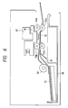
- the structure of this mechanism for example, provided in an ink jet recording apparatus, is such that recording media 51 stacked in a cassette 50 are one-by-one fed out by a pick-up roller 52, and sandwiched and transported by a pair of transporting rollers 53a, 53b and a pair of discharging rollers 54a, 54b, as shown in Fig. 6.
- a carriage 56 is reciprocally moved in the direction vertical to the surface of Fig. 6 relative to the recording medium 52 which has the rear surface supported by a platen 55, while ink is discharged from a recording head 57 mounted on the carriage 56.
- the ink jet head 57 faces the recording medium 51 from above the transporting roller pair 52a, 53b and the discharging roller pair 54a, 54b, and is scanned at a location close to the platen 55 which is positioned at a height substantially equal to nips of both roller pairs 53a, 53b and 54a, 54b, whereby if an abnormal transportation (jam) of the recording medium occurs in course of a recording operation and the recording operation is to be stopped to treat the jam, the following problems arises:
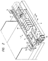
- Fig. 1 is an explanatory cross-sectional view showing a main portion of a recording apparatus
- Fig. 2 is an explanatory perspective view
- Fig. 3 is an explanatory cross-sectional view showing a state where a recording medium is released from being sandwiched by transporting means with a platen being separated from the recording medium.
- This recording apparatus sandwiches a fed recording medium 1 such as paper or plastic sheet by transporting means 2 to transport the recording medium 1 in the direction indicated by a , and reciprocally moves recording means 4 relative to the recording medium 1 having its rear surface supported by a platen 3 to perform recording on the recording medium 1, and discharges the thus recorded recording medium 1 to a discharging tray, not shown.
- a fed recording medium 1 such as paper or plastic sheet
- transporting means 2 to transport the recording medium 1 in the direction indicated by a
- recording means 4 reciprocally moves recording means 4 relative to the recording medium 1 having its rear surface supported by a platen 3 to perform recording on the recording medium 1, and discharges the thus recorded recording medium 1 to a discharging tray, not shown.
- a releasing means 5 is used to separate the platen 3 relative to the recording means 4, and the sandwiching of the recording medium 1 by the transporting means 2 is released.
- the transporting means 2 is provided mainly for transporting the recording medium 1, it has another function as a cramping means for cramping the recording medium 1 in a sandwiched state during a recording operation.
- the transporting means 2 is disposed at a location upstream of a recording position in the transporting direction of the recording medium 1, and comprises a pair of transporting rollers 2a, 2b for sandwiching and transporting the recording medium 1 to the recording position, and a pair of discharging rollers 2c, 2d, disposed at a location downstream of the recording position for discharging the recorded recording medium 1 to a discharging tray.
- the transporting lower roller 2a and the discharging lower roller 2c are coupled to a transporting motor 2e and rotated by the same, while the transporting upper roller 2b and the discharging upper roller 2d are rotatably attached at one end of a transporting arm 2h and a discharging arm 2i, respectively, which are pivotable on shafts 2f, 2g, respectively.
- Tension springs 2j, 2k engaged at the other ends of the arms 2h, 2i press the transporting and discharging upper rollers 2b, 2d to be in contact with the transporting and discharging lower rollers 2a, 2c, respectively.
- the recording means 4 records an ink image on the recording medium 1 which is transported by the transporting means 2.
- the apparatus of this embodiment employs a serial-type ink jet recording method, wherein a carriage 4a is reciprocally moved while a recording head 4b discharges liquid ink for recording.
- the carriage 4a is mounted so as to be slidable along and pivotable on a guiding rail 4c which is disposed in the width direction of the recording medium 1 (the direction perpendicular to the transporting direction of the recording medium 1). Further, in the vicinity of both ends of the guiding rail 4c, there are disposed a driving pulley 4d and a dependent pulley 4e. An endless timing belt 4f passed about both pulleys 4d, 4e is connected to the carriage 4a. Therefore, when the carriage motor 4g coupled to the driving pulley 4c is driven in the forward and backward directions, the carriage 4a reciprocally moves guided by the guiding rail 4c.
- a recording head assembly 4b which is integrated with an ink cartridge.
- This ink head assembly 4b comprises four heads 4b1, 4b2, 4b3 and 4b4 respectively integrated with cartridges containing yellow, magenta, cyan and black ink.
- the recording head assembly 4b discharges ink in respective colors in response to an image signal, while the carriage 4a reciprocally moves, to perform color recording on the recording medium 1.
- the recording head assembly 4b comprises fine liquid discharging ports (orifices); a liquid pathway; an energy acting portion formed in part of this liquid pathway; and an energy generating means for generating energy which is acted on a liquid in the acting portion to form liquid droplets.
- an energy generating means there are a recording method employing an electro-mechanical transducer such as a piezo element; a recording method employing an energy generating means which generates heat by irradiating electro-magnetic wave such as a laser and discharging liquid droplets by the action of the heat generation; a recording method employing an energy generating means which heats a liquid by an electro-thermal transducer such as a heat generating element having a heat generating resistor or the like to discharge the liquid; and so on.
- a recording head employed in an ink jet recording method which discharges a liquid by thermal energy can be provided with highly densely aligned liquid discharging ports (orifices) for forming liquid droplets to be discharged, whereby recording in high resolution is achieved.
- a recording head which employs an electro-thermal transducer as an energy generating means is advantageous because this type of recording head can be readily reduced in size, sufficiently utilize the advantages of the IC technology and micro machining technique in which the technological advance and reliability have been remarkably improved in the recent semiconductor field, and be easily mounted in a high density with a lower manufacturing cost.
- the platen 3 supports the recording medium 1 from the rear surface thereof at the recording position, and the platen plane is positioned at a height substantially equal to that of the transporting plane of the recording medium 1 transported by the transporting means 2.
- a rotatable roller 4h is mounted at a position opposite to the platen 3 in the carriage 4a as shown in Fig. 1.
- the carriage 4a is rotatable around the guiding rail 4c, and due to the self-weight of the carriage 4a a force in the clock-wise direction in Fig. 2 acts on the carriage 4a.
- the releasing means 5 separates the platen 3 away from the ink discharging plane of the recording head assembly 4b and releases the recording medium 1 sandwiched between the transporting means 2.
- the transporting lower roller 2a, the discharging lower roller 2c and the platen 3 are mounted on an elevator stand 5a which makes them movable in the vertical direction.
- the elevator stand 5a At both ends of the elevator stand 5a there are formed guiding grooves 5b1, 5b2 in the vertical direction, in which fitted are guiding pins 5c1, 5c2, respectively, which are secured at fixed positions of the apparatus body.
- the elevator stand 5a can rise and fall in the vertical direction while guided by these guiding grooves 5b1, 5b2 and the guiding pins 5c1, 5c2.
- Manipulation of a lever 5d causes the elevator stand 5a to rise and fall through an intermediate arm 5e and a lifting arm 5f.
- the lever 5d is pivotably supported on a lever shaft 5g secured on the apparatus body.
- a cam 5h is also secured integrally with the lever 5d so as to be pivotable on the lever shaft 5g together with the lever 5d.
- This cam 5h has a cam face (a larger diameter portion) 5h1 on an arc spaced from the center of the lever shaft 5g by a large distance and a cam face (a smaller diameter portion) 5h2 spaced by a shorter distance from the center of the lever shaft 5g.
- the intermediate arm 5e is pivotably supported by an arm shaft 5i secured on the apparatus body, where a cam follower face 5e1 formed at one end thereof is located to be contactable with the cam 5h, and is applied with a pivoting force from the cam 5h.
- the other end of the intermediate arm 5e is formed with a hook 5e2 which is engaged with one end of a tension spring 5j.
- the lifting arm 5f is pivotably supported by an arm shaft 5k, where an engaging hole 5f1 formed therethrough in an upper right portion is engaged with the other end of the tension spring 5j, and the upper end thereof pivotably supports an urging roller 5m.
- a stopper pin 5n1 is secured on the apparatus body spaced by a slight distance from an edge 2h1 in an upper left end portion of the transporting arm 2h
- a stopper pin 5n2 is secured on the apparatus body spaced by a slight distance from an edge 2i1 in an upper right end portion of the discharging arm 2i.
- a stopper shaft 5o is secured on the apparatus body spaced by a slight distance from the carriage 4a and in parallel to the guiding rail 4c.
- the releasing means 5 if the lever 5d has been switched to a position shown in Fig. 1 during a normal recording operation, the large diameter portion 5h1 of the cam 5h pushes down the cam follower face 5e1, while the urging roller 5m pushes up the elevator stand 5e through the elasticity of the tension spring 5j.
- the elevator stand 5a is positioned by the guiding pins 5c1, 5c2 which are brought into contact with the lower ends of the guiding grooves 5b1, 5b2.
- the transporting roller pair 2a, 2b and the discharging roller pair 2c, 2d are pressed to each other, and the recording head assembly 4b faces the platen 3 with a predetermined distance therebetween.
- the transporting motor 2e and the carriage motor 4g are driven and the recording head assembly 4b is driven in response to an image signal, the recording medium 1 is intermittently transported while an image is recorded on the recording medium 1.
- a control means provided in the apparatus body after detecting a signal indicative of the abnormality, stops all operating systems and informs the operator of the abnormality by an alarming display or the like.
- the lever 5d is rotated in the counter-clockwise direction as shown in Fig. 3.
- the elevator stand 5a guided by the guiding pins 5c1, 5c2, is going to vertically fall by the self-weight, which acts on the urging roller 5m supported by the lifting arm 5f. A rotating force is thus acting on the lifting arm 5f in the counter-clockwise direction.
- the transporting arm 2h supporting the transporting upper roller 2a is going to rotate in the clockwise direction by the action of the spring 2j
- the discharging arm 2i supporting the discharging upper roller 2c is going to rotate in the counter-clockwise direction by the action of the spring 2k.
- the rotations are restricted at the time the respective arms 2j, 2i come in contact with the stopper pins 5n1, 5n2, respectively.
- the transporting lower roller 2a and the discharging lower roller 2c are lowered and separated from the transporting upper roller 2b and the discharging upper roller 2d, respectively, whereby the recording medium 1 sandwiched therebetween is released.
- the jammed recording medium 1 can be easily removed in this manner.
- FIG. 4 is a cross-sectional view for explaining a main portion of a recording apparatus according to this embodiment; and Fig. 5 is an explanatory cross-sectional view showing a state where releasing means is operated to perform a jam recovery treatment.
- Members in these drawings having similar functions to those in the foregoing embodiment are designated the same reference numerals.
- a transporting lower roller 2a and a discharging lower roller 2c are rotatably supported at fixed position of the apparatus body, and coupled to a motor, not shown, to be applied with a rotating force. Between these rollers 2a, 2c, a platen 3 is disposed.
- a transporting arm 2h is pivotable on an arm shaft 2f secured on the apparatus body and rotatably supports a transporting upper roller 2b at the right end thereof. Also, at the left end of the transporting arm 2h one end of a tension spring 2j is engaged. The other end of the tension spring 2j is secured at a fixed position on the apparatus body to apply the transporting arm 2h with a rotating force in the clockwise direction, whereby the transporting upper roller 2b is pressed to the transporting lower roller 2a.
- the transporting arm 2h has, on the upper arm side thereof, an even portion 2h1 parallel to the axial direction of the transporting lower roller 2a, which is integrated with a second transporting arm, not shown, which is at a position symmetric to the position of the transporting arm 2h on the other end side in the axial direction of the transporting lower roller 2a and supports the transporting lower roller 2a.
- a bent portion 2h2 at the right end of the even portion 2h1 is spaced close to the lower surface of the carriage 4a, such that, assuming that the transporting arm 2h is rotated around the arm shaft 2f in the counter-clockwise direction, the bent portion 2h2 pushes up the carriage 4a.
- a discharging arm 2i is pivotable on an arm shaft 2g secured on the apparatus body and rotatably supports the discharging upper roller 2d at the left end thereof. Also, the discharging arm 2i has at the right end thereof a hook to which one end of a tension spring 2k is engaged. The other end of the tension spring 2k is secured at a fixed position on the apparatus body and applies the discharging arm 2i with a rotating force in the counter-clockwise direction, whereby the discharging upper roller 2d is pressed to the discharging lower roller 2c.
- a first cam 6a1 is rotatable integrally with a cam shaft 6b1.
- a large diameter portion of the cam 6a1 is positioned such that it can be engaged with an upper edge of a lower arm of the transporting arm 2h when a predetermined rotating amount is applied to the cam shaft 6b1.
- a second cam 6a2 located on the discharging side is rotatable integrally with a cam shaft 6b2.
- a large diameter portion of the cam 6a2 is positioned such that is can be engaged with an upper edge of a lower arm of the discharging arm 2i when a predetermined rotating amount is applied to the cam shaft 6b2.
- the cam shafts 6b1, 6b2 are coupled to gears 6c1, 6c2, respectively, outside the transporting area of the recording medium 1. Both gears 6c1, 6c2 are operatively meshed with each other by way of gears 7, 8, 9 and 10 in a manner that they are associated with their phases of rotating angles related to each other. For example, if the operator rotates a lever, not shown, which is coupled with any of the foregoing gears, a rotating amount applied to the lever is transmitted through the train of gears.
- the upper bent portion 2h2 of the transporting arm 2h pushes up the lower surface of the carriage 4a which in turn is rotated around the guiding rail 4c in the counter-clockwise direction, whereby the distance between the platen 3 and the recording head assembly 4b becomes wider.
- the operator therefore, can easily remove the recording medium 1 which has been sandwiched between the rollers 2a, 2b and 2c, 2d without damaging the recording head assembly 4b.
- lever 5d may be coupled to a motor or the like to be electrically driven.
- the above described embodiments each have shown an example, where the recording medium 1 sandwiched by the roller pairs constituting the transporting means 2 is released, however, the clamping of the recording medium made by alternative sandwiching mechanism or pressing mechanism may also be released by the releasing means.
- the ink jet recording method has been employed for the recording means, it is further preferable that the recording means is constructed in a manner that an electro-thermal transducer is conducted in accordance with a recording signal, and ink is discharged from discharging ports to perform recording by the growth of bubbles generated by heating of the electro-thermal transducer exceeding film boiling.
- This recording system is applicable to either of so-called on-demand type and continuous type.
- this recording system is effective in the on-demand type, where an electro-thermal transducer arranged corresponding to a sheet and a liquid pathway, in which ink is held, is applied with at least one driving signal corresponding to recording information for giving a rapid temperature rise to ink to exceed nuclear boiling and cause film boiling, whereby thermal energy is generated to cause film boiling on a heat acting face of a recording head, and consequently, bubbles which correspond one by one to the driving signal applied to the electro-thermal transducer can be formed in the ink.
- the ink is discharged from discharging orifices by the action of growth and contraction of bubbles to form at least one droplet. It is preferable that a pulse signal is used as the driving signal because the growth and contraction of bubbles are immediately and properly performed by such a pulse-shaped driving signal, whereby particularly excellent ink discharge can be achieved.
- the structure of the recording head according to the present invention includes such one that employes structures described in the specifications of U.S. Patent Nos. 4,558,333 and 4,459,600 which disclose a structure in which a heat acting portion is arranged in a bent region, in addition to a combined structure (a straight flow pathway or a perpendicular flow pathway) formed of discharging orifices, a liquid pathway and an electro-thermal transducer as disclosed in the above-mentioned respective specifications.
- the present invention is also effective when the recording head is constructed on the basis of Japanese Laid-open Patent Application No. 59-123670 which discloses a structure where common slits serve as discharging orifices for a plurality of electro-thermal transducers and Japanese Laid-open Patent Application No. 59-138461 which discloses a structure where an opening for absorbing pressure wave of thermal energy is arranged corresponding to a discharging section. After all, the present invention ensures to perform efficient recording irrespective of the shape of the recording head.
- the present invention is also applicable to a recording head of full line type which has a length corresponding to the width of the widest recording medium on which a recording apparatus can record.
- This full line head may be constituted by either an assembly of a plurality of recording heads extending over the full line length or a single integrated full-line recording head.
- the present invention may also employ an exchangeable chip-type recording head to which electric connection with the recording apparatus and ink supply from the recording apparatus are enabled by mounting the head in the recording apparatus, or a cartridge type recording head which has an ink tank integrated therewith.
- a recovering means for a recording head, a preparatory supporting means and so on which may be provided as constituents of the recording apparatus of the present invention, is preferable since the effect of the present invention can be further stabilized by these means.
- these means may be a capping means; a cleaning means; a pressurizing or sucking means; and a preparatory heating means comprising an electro-thermal transducer or an alternative heating element, or a combination of these two elements. It is also effective for stable recording to perform a preparatory discharging mode which executes other discharging than that for the recording purpose.
- the recording apparatus of the present invention may be provided with, for example, a plurality of recording heads corresponding to a plurality of ink respectively having a different color and concentration, other than a single recording head corresponding to single color ink.
- the recording mode for the recording apparatus may be either of a main color recording mode, in which recording is performed only in a main color such as black, and a combined color mode using a plurality of integrated recording heads.
- the present invention is also applicable to an apparatus which executes at least one of a plural color recording mode using different colors and a full color recording mode achieved by mixing different colors.
- ink was explained as a liquid, the ink may be such one that is solidified at temperatures less than room temperatures and softened or liquified at room temperatures.
- the ink jet recording apparatus generally controls the temperature of ink in a range between 30°C and 70°C to maintain the viscosity of the ink in a stably dischargeable state, any ink may be used as long as it is in a liquid state when a recording signal is supplied.
- ink which is solid in an unused state
- ink which is solid in an unused state
- the present invention is applicable to the use of ink having the characteristics of being liquified only by applying thermal energy thereto, e.g., ink which is liquified and discharged by applying thereto thermal energy in response to a recording signal; ink which has already begun solidifying when reaching a recording medium; and so on.
- the ink for these cases may be such one that is stored in liquid or solid state within cavities or throughholes in a porous sheet and arranged opposite to an electro-thermal transducer, as described in Japanese Patent Laid-open Applications No. 54-56847 or 60-71260.
- the most effective apparatus for the above-mentioned respective ink is the one which executes the foregoing film boiling method.
- the foregoing ink jet recording apparatus may form, other than that used as an image outputting terminal for an information processing apparatus such as a computer, a copier combined with a reader or the like, a facsimile apparatus having transmitting and receiving functions, and so on.
- the present invention is not necessarily limited to the ink jet recording method but can be applicable to a thermal transfer recording method, a heat sensitive recording method, and recording methods other than the impact recording method such as a wire dot recording method.
- the present invention need not be limited either to a serial recording method but may employ a so-called line recording method.
- the platen for performing a jam recovery treatment or the like, the platen is separated from the recording means by the releasing means and a recording medium is released from a sandwiched state by a transporting means functioning as a clamping means.
- This operation facilitates a jam recovery treatment for recording medium as well as prevents the recording means from being damaged by the recording medium.
- the present invention provides a releasing means for separating a recording means from a platen and releasing a recording medium from a clamped state, as described above, so that if a jammed recording medium is to be treated, by way of example, the operator can easily removed the jammed recording medium without damaging the recording means.
- a recording apparatus comprises transporting rollers for transporting a recording medium in a sandwiched state; a platen for supporting the recording medium at a recording position; and a releasing mechanism for moving the platen from a position at which the platen is located during a recording operation and releasing the recording medium sandwiched by the transporting rollers.
Abstract
Description
- The present invention relates to a recording apparatus for use in a printer, copier, facsimile apparatus and so on for recording an image on a recording medium such as paper, plastic sheet and so on.
- Generally, a recording apparatus having a recording mechanism of ink jet type, a heat-sensitive transfer recording mechanism, or the like performs a recording operation while scanning the recording mechanism relative to a recording medium to generate a two-dimensional image.
- The structure of this mechanism, for example, provided in an ink jet recording apparatus, is such that
recording media 51 stacked in acassette 50 are one-by-one fed out by a pick-up roller 52, and sandwiched and transported by a pair oftransporting rollers discharging rollers carriage 56 is reciprocally moved in the direction vertical to the surface of Fig. 6 relative to therecording medium 52 which has the rear surface supported by aplaten 55, while ink is discharged from arecording head 57 mounted on thecarriage 56. - In the above-mentioned structure, however, the
ink jet head 57 faces therecording medium 51 from above the transportingroller pair 52a, 53b and thedischarging roller pair platen 55 which is positioned at a height substantially equal to nips of bothroller pairs - (1) When the
upper rollers recording medium 51 from bothroller pairs carriage 56 touches these upper rollers. Thus, a sufficient space cannot be assured for therollers jammed recording medium 51, thereby making the jam recovery treatment difficult. - (2) When a jam occurs, the
recording medium 51 on theplaten 55 may often be raised off theplaten 55. If thecarriage 56 is returned to the home position, an ink discharging surface of therecording head 57 may be rubbed by therecording medium 51, which possibly leads to damaging nozzle tips of therecording head 57. - It is an object of the present invention to provide a recording apparatus for solving the above-mentioned conventional problems which maintains a high recording quality and reliability and facilitates the maintenance.
- It is another object of the present invention to provide a recording apparatus which allows the operator to easily remove a jammed recording medium without damaging recording means.
- It is a further object of the present invention to provide a recording apparatus which has transporting means for transporting a recording medium in a sandwiched state; supporting means for supporting the recording medium at a recording position; and releasing means for moving the supporting means from a position at which the supporting means is located during a recording operation and releasing the recording medium sandwiched by the transporting means.
-
- Fig. 1 is a cross-sectional view for explaining a main portion of a recording apparatus according to an embodiment of the present invention;
- Fig. 2 is a perspective view for explaining the interior of the recording apparatus of the embodiment;
- Fig. 3 is an explanatory cross-sectional view showing a state where a recording medium is released from a sandwiched state by transporting means of the embodiment, and a platen is separated;
- Fig. 4 is a cross-sectional view for explaining a main portion of a recording apparatus according to another embodiment;
- Fig. 5 is an explanatory cross-sectional view showing a state where a recording medium is released from a sandwiched state by transporting means of the other embodiment, and a platen is separated; and
- Fig. 6 is a diagram for explaining a prior art.
- Embodiments according to the present invention applying the foregoing means will now be described.
- One embodiment will first be described with reference to Figs. 1 - 3. Fig. 1 is an explanatory cross-sectional view showing a main portion of a recording apparatus; Fig. 2 is an explanatory perspective view; and Fig. 3 is an explanatory cross-sectional view showing a state where a recording medium is released from being sandwiched by transporting means with a platen being separated from the recording medium.
- This recording apparatus, as shown in Fig. 2, sandwiches a
fed recording medium 1 such as paper or plastic sheet by transportingmeans 2 to transport therecording medium 1 in the direction indicated by a, and reciprocally moves recording means 4 relative to therecording medium 1 having its rear surface supported by aplaten 3 to perform recording on therecording medium 1, and discharges the thus recordedrecording medium 1 to a discharging tray, not shown. - When a jam is treated in this recording apparatus, a releasing means 5 is used to separate the
platen 3 relative to the recording means 4, and the sandwiching of therecording medium 1 by the transportingmeans 2 is released. - Next, the foregoing each section will be specifically described.
- Although the
transporting means 2 is provided mainly for transporting therecording medium 1, it has another function as a cramping means for cramping therecording medium 1 in a sandwiched state during a recording operation. As shown in Figs. 1 and 2, the transportingmeans 2 is disposed at a location upstream of a recording position in the transporting direction of therecording medium 1, and comprises a pair oftransporting rollers recording medium 1 to the recording position, and a pair ofdischarging rollers recording medium 1 to a discharging tray. The transportinglower roller 2a and the discharginglower roller 2c are coupled to a transportingmotor 2e and rotated by the same, while the transportingupper roller 2b and the dischargingupper roller 2d are rotatably attached at one end of a transportingarm 2h and adischarging arm 2i, respectively, which are pivotable onshafts arms upper rollers lower rollers motor 2e is driven, therecording medium 1 is sandwiched between and transported by the transportingroller pair discharging roller pair - The recording means 4 records an ink image on the
recording medium 1 which is transported by thetransporting means 2. The apparatus of this embodiment employs a serial-type ink jet recording method, wherein acarriage 4a is reciprocally moved while arecording head 4b discharges liquid ink for recording. - The
carriage 4a is mounted so as to be slidable along and pivotable on a guiding rail 4c which is disposed in the width direction of the recording medium 1 (the direction perpendicular to the transporting direction of the recording medium 1). Further, in the vicinity of both ends of the guiding rail 4c, there are disposed a driving pulley 4d and adependent pulley 4e. Anendless timing belt 4f passed about bothpulleys 4d, 4e is connected to thecarriage 4a. Therefore, when the carriage motor 4g coupled to the driving pulley 4c is driven in the forward and backward directions, thecarriage 4a reciprocally moves guided by the guiding rail 4c. - On the
carriage 4a, there is mounted arecording head assembly 4b which is integrated with an ink cartridge. Thisink head assembly 4b comprises four heads 4b1, 4b2, 4b3 and 4b4 respectively integrated with cartridges containing yellow, magenta, cyan and black ink. Therecording head assembly 4b discharges ink in respective colors in response to an image signal, while thecarriage 4a reciprocally moves, to perform color recording on therecording medium 1. - The
recording head assembly 4b comprises fine liquid discharging ports (orifices); a liquid pathway; an energy acting portion formed in part of this liquid pathway; and an energy generating means for generating energy which is acted on a liquid in the acting portion to form liquid droplets. As such an energy generating means, there are a recording method employing an electro-mechanical transducer such as a piezo element; a recording method employing an energy generating means which generates heat by irradiating electro-magnetic wave such as a laser and discharging liquid droplets by the action of the heat generation; a recording method employing an energy generating means which heats a liquid by an electro-thermal transducer such as a heat generating element having a heat generating resistor or the like to discharge the liquid; and so on. Among these recording methods, a recording head employed in an ink jet recording method which discharges a liquid by thermal energy can be provided with highly densely aligned liquid discharging ports (orifices) for forming liquid droplets to be discharged, whereby recording in high resolution is achieved. Above all, a recording head which employs an electro-thermal transducer as an energy generating means is advantageous because this type of recording head can be readily reduced in size, sufficiently utilize the advantages of the IC technology and micro machining technique in which the technological advance and reliability have been remarkably improved in the recent semiconductor field, and be easily mounted in a high density with a lower manufacturing cost. - The
platen 3 supports therecording medium 1 from the rear surface thereof at the recording position, and the platen plane is positioned at a height substantially equal to that of the transporting plane of therecording medium 1 transported by thetransporting means 2. - In the ink jet recording method, it is necessary to reduce the distance between the
recording medium 1 and therecording head assembly 4 as short as possible in order to ensure the impact accuracy of discharged ink. For this reason, the distance between theplaten 3 and therecording head assembly 4 is set to be a small value. In this embodiment, arotatable roller 4h is mounted at a position opposite to theplaten 3 in thecarriage 4a as shown in Fig. 1. Thecarriage 4a is rotatable around the guiding rail 4c, and due to the self-weight of thecarriage 4a a force in the clock-wise direction in Fig. 2 acts on thecarriage 4a. By a rolling contact of theroller 4h with theplaten 3 or that of theroller 4h with therecording medium 1 on theplaten 3, the posture of thecarriage 4a in the rotating direction is determined, and the distance between therecording head 4a and theplaten 3 is defined. - The releasing means 5 separates the
platen 3 away from the ink discharging plane of therecording head assembly 4b and releases therecording medium 1 sandwiched between thetransporting means 2. In this embodiment, as shown in Fig. 1, the transportinglower roller 2a, the discharginglower roller 2c and theplaten 3 are mounted on an elevator stand 5a which makes them movable in the vertical direction. - At both ends of the elevator stand 5a there are formed guiding grooves 5b1, 5b2 in the vertical direction, in which fitted are guiding pins 5c1, 5c2, respectively, which are secured at fixed positions of the apparatus body. Thus, the elevator stand 5a can rise and fall in the vertical direction while guided by these guiding grooves 5b1, 5b2 and the guiding pins 5c1, 5c2.
- Manipulation of a
lever 5d causes the elevator stand 5a to rise and fall through anintermediate arm 5e and alifting arm 5f. Thelever 5d is pivotably supported on alever shaft 5g secured on the apparatus body. Acam 5h is also secured integrally with thelever 5d so as to be pivotable on thelever shaft 5g together with thelever 5d. Thiscam 5h has a cam face (a larger diameter portion) 5h1 on an arc spaced from the center of thelever shaft 5g by a large distance and a cam face (a smaller diameter portion) 5h2 spaced by a shorter distance from the center of thelever shaft 5g. - The
intermediate arm 5e is pivotably supported by anarm shaft 5i secured on the apparatus body, where a cam follower face 5e1 formed at one end thereof is located to be contactable with thecam 5h, and is applied with a pivoting force from thecam 5h. The other end of theintermediate arm 5e is formed with a hook 5e2 which is engaged with one end of atension spring 5j. - The
lifting arm 5f is pivotably supported by anarm shaft 5k, where an engaging hole 5f1 formed therethrough in an upper right portion is engaged with the other end of thetension spring 5j, and the upper end thereof pivotably supports an urgingroller 5m. - In a state where the transporting
roller pair roller pair arm 2h, and a stopper pin 5n2 is secured on the apparatus body spaced by a slight distance from an edge 2i1 in an upper right end portion of the dischargingarm 2i. Further, on the lower right side of thecarriage 4a, a stopper shaft 5o is secured on the apparatus body spaced by a slight distance from thecarriage 4a and in parallel to the guiding rail 4c. - In the foregoing structure of the releasing means 5, if the
lever 5d has been switched to a position shown in Fig. 1 during a normal recording operation, the large diameter portion 5h1 of thecam 5h pushes down the cam follower face 5e1, while the urgingroller 5m pushes up theelevator stand 5e through the elasticity of thetension spring 5j. In this event, the elevator stand 5a is positioned by the guiding pins 5c1, 5c2 which are brought into contact with the lower ends of the guiding grooves 5b1, 5b2. By this operation, the transportingroller pair roller pair recording head assembly 4b faces theplaten 3 with a predetermined distance therebetween. In this condition, if the transportingmotor 2e and the carriage motor 4g are driven and therecording head assembly 4b is driven in response to an image signal, therecording medium 1 is intermittently transported while an image is recorded on therecording medium 1. - On the other hand, if an abnormal transporting arises during a recording operation, a control means provided in the apparatus body, after detecting a signal indicative of the abnormality, stops all operating systems and informs the operator of the abnormality by an alarming display or the like. When the operator is to perform a jam treatment in response to this, the
lever 5d is rotated in the counter-clockwise direction as shown in Fig. 3. The elevator stand 5a, guided by the guiding pins 5c1, 5c2, is going to vertically fall by the self-weight, which acts on the urgingroller 5m supported by thelifting arm 5f. A rotating force is thus acting on thelifting arm 5f in the counter-clockwise direction. Simultaneously, a rotating force is acting on theintermediate arm 5e in the counter-clockwise direction through thetension spring 5j. Therefore, the rotation of thelever 5d in the counter-clockwise direction causes the cam face in contact with the cam follower face 5e1 of theintermediate arm 5e to change from the large diameter portion 5h1 to the small diameter portion 5h2, whereby theintermediate arm 5e is released from the forced rotation in the counter-clockwise direction. Consequently, theintermediate arm 5e and thelifting arm 5f rotate in the counter-clockwise direction, which leads to lowering the urgingroller 5m, and the elevator stand 5a responsively falls. - With the falling of the elevator stand 5a, the transporting
arm 2h supporting the transportingupper roller 2a is going to rotate in the clockwise direction by the action of thespring 2j, whereas the dischargingarm 2i supporting the dischargingupper roller 2c is going to rotate in the counter-clockwise direction by the action of thespring 2k. However, the rotations are restricted at the time therespective arms lower roller 2a and the discharginglower roller 2c are lowered and separated from the transportingupper roller 2b and the dischargingupper roller 2d, respectively, whereby therecording medium 1 sandwiched therebetween is released. Thejammed recording medium 1 can be easily removed in this manner. - With the falling of the elevator stand 5a, the
carriage 4a is going to rotate around the guiding rail 4c in the clockwise direction, however, this rotation is restricted at a time thecarriage 4a comes in contact with the stopper shaft 5o. For this reason, a relative distance between the fallingplaten 3 and therecording head assembly 4b becomes larger, so that the ink discharging plane of therecording head assembly 4b will never be rubbed by therecording medium 1 during a jam recovery treatment, thereby preventing therecording head assembly 4b from being damaged. In the recording apparatus of this embodiment, when thelever 5d of the releasing means 5 is manipulated as described above, therecording medium 1 sandwiched between the transportingmeans 2 is released, and therecording head 4b is separated from theplaten 3, making it possible to facilitate a jam recovery treatment. - Next, another embodiment having releasing means in a different structure will be described with reference to Figs. 4 and 5. Fig. 4 is a cross-sectional view for explaining a main portion of a recording apparatus according to this embodiment; and Fig. 5 is an explanatory cross-sectional view showing a state where releasing means is operated to perform a jam recovery treatment. Members in these drawings having similar functions to those in the foregoing embodiment are designated the same reference numerals.
- Referring to Fig. 4, a transporting
lower roller 2a and a discharginglower roller 2c are rotatably supported at fixed position of the apparatus body, and coupled to a motor, not shown, to be applied with a rotating force. Between theserollers platen 3 is disposed. A transportingarm 2h is pivotable on anarm shaft 2f secured on the apparatus body and rotatably supports a transportingupper roller 2b at the right end thereof. Also, at the left end of the transportingarm 2h one end of atension spring 2j is engaged. The other end of thetension spring 2j is secured at a fixed position on the apparatus body to apply the transportingarm 2h with a rotating force in the clockwise direction, whereby the transportingupper roller 2b is pressed to the transportinglower roller 2a. - The transporting
arm 2h has, on the upper arm side thereof, an even portion 2h1 parallel to the axial direction of the transportinglower roller 2a, which is integrated with a second transporting arm, not shown, which is at a position symmetric to the position of the transportingarm 2h on the other end side in the axial direction of the transportinglower roller 2a and supports the transportinglower roller 2a. - A bent portion 2h2 at the right end of the even portion 2h1 is spaced close to the lower surface of the
carriage 4a, such that, assuming that the transportingarm 2h is rotated around thearm shaft 2f in the counter-clockwise direction, the bent portion 2h2 pushes up thecarriage 4a. - A discharging
arm 2i is pivotable on anarm shaft 2g secured on the apparatus body and rotatably supports the dischargingupper roller 2d at the left end thereof. Also, the dischargingarm 2i has at the right end thereof a hook to which one end of atension spring 2k is engaged. The other end of thetension spring 2k is secured at a fixed position on the apparatus body and applies the dischargingarm 2i with a rotating force in the counter-clockwise direction, whereby the dischargingupper roller 2d is pressed to the discharginglower roller 2c. - A first cam 6a1 is rotatable integrally with a cam shaft 6b1. A large diameter portion of the cam 6a1 is positioned such that it can be engaged with an upper edge of a lower arm of the transporting
arm 2h when a predetermined rotating amount is applied to the cam shaft 6b1. On the other hand, a second cam 6a2 located on the discharging side is rotatable integrally with a cam shaft 6b2. A large diameter portion of the cam 6a2 is positioned such that is can be engaged with an upper edge of a lower arm of the dischargingarm 2i when a predetermined rotating amount is applied to the cam shaft 6b2. - The cam shafts 6b1, 6b2 are coupled to gears 6c1, 6c2, respectively, outside the transporting area of the
recording medium 1. Both gears 6c1, 6c2 are operatively meshed with each other by way ofgears - In the above-mentioned structure, for performing a jam recovery treatment, when the operator manipulates a lever, not shown, to rotate the cam shafts 6b1, 6b2 to rotate the cams 6a1, 6a2 substantially over 180° from the state shown in Fig. 4, the large diameter portions of the cams 6a1, 6a2 engage with the upper edges of the lower arms of the
arms arm 2h is rotated in the counter-clockwise direction while the dischargingarm 2i is rotated in the clockwise direction. further, the upper bent portion 2h2 of the transportingarm 2h pushes up the lower surface of thecarriage 4a which in turn is rotated around the guiding rail 4c in the counter-clockwise direction, whereby the distance between theplaten 3 and therecording head assembly 4b becomes wider. The operator, therefore, can easily remove therecording medium 1 which has been sandwiched between therollers recording head assembly 4b. - Although this embodiment has shown an example where the
lever 5d is manually rotated, thelever 5d may be coupled to a motor or the like to be electrically driven. - Also, the above described embodiments each have shown an example, where the
recording medium 1 sandwiched by the roller pairs constituting the transportingmeans 2 is released, however, the clamping of the recording medium made by alternative sandwiching mechanism or pressing mechanism may also be released by the releasing means. - Although in the foregoing embodiments, the ink jet recording method has been employed for the recording means, it is further preferable that the recording means is constructed in a manner that an electro-thermal transducer is conducted in accordance with a recording signal, and ink is discharged from discharging ports to perform recording by the growth of bubbles generated by heating of the electro-thermal transducer exceeding film boiling.
- The typical structure and principle of this type of recording apparatus preferably employ the basic principles disclosed, for example, in U.S. Patent Nos. 4,723,129 and 4,740,796. This recording system is applicable to either of so-called on-demand type and continuous type. Particularly, this recording system is effective in the on-demand type, where an electro-thermal transducer arranged corresponding to a sheet and a liquid pathway, in which ink is held, is applied with at least one driving signal corresponding to recording information for giving a rapid temperature rise to ink to exceed nuclear boiling and cause film boiling, whereby thermal energy is generated to cause film boiling on a heat acting face of a recording head, and consequently, bubbles which correspond one by one to the driving signal applied to the electro-thermal transducer can be formed in the ink. The ink is discharged from discharging orifices by the action of growth and contraction of bubbles to form at least one droplet. It is preferable that a pulse signal is used as the driving signal because the growth and contraction of bubbles are immediately and properly performed by such a pulse-shaped driving signal, whereby particularly excellent ink discharge can be achieved.
- As this pulse-shaped driving signal, those described in the specifications of U.S. Patent Nos. 4,463,359 and 4,345,262 are suitable.
- Further, if conditions described in the specification of U.S. Patent No. 4,313,124 concerning a temperature rising ratio on the heat acting face are employed, further excellent recording can be achieved.
- It should be noted that the structure of the recording head according to the present invention includes such one that employes structures described in the specifications of U.S. Patent Nos. 4,558,333 and 4,459,600 which disclose a structure in which a heat acting portion is arranged in a bent region, in addition to a combined structure (a straight flow pathway or a perpendicular flow pathway) formed of discharging orifices, a liquid pathway and an electro-thermal transducer as disclosed in the above-mentioned respective specifications.
- Additionally, the present invention is also effective when the recording head is constructed on the basis of Japanese Laid-open Patent Application No. 59-123670 which discloses a structure where common slits serve as discharging orifices for a plurality of electro-thermal transducers and Japanese Laid-open Patent Application No. 59-138461 which discloses a structure where an opening for absorbing pressure wave of thermal energy is arranged corresponding to a discharging section. After all, the present invention ensures to perform efficient recording irrespective of the shape of the recording head.
- The present invention is also applicable to a recording head of full line type which has a length corresponding to the width of the widest recording medium on which a recording apparatus can record.
- This full line head may be constituted by either an assembly of a plurality of recording heads extending over the full line length or a single integrated full-line recording head.
- Additionally, the present invention may also employ an exchangeable chip-type recording head to which electric connection with the recording apparatus and ink supply from the recording apparatus are enabled by mounting the head in the recording apparatus, or a cartridge type recording head which has an ink tank integrated therewith.
- Also, the addition of a recovering means for a recording head, a preparatory supporting means and so on, which may be provided as constituents of the recording apparatus of the present invention, is preferable since the effect of the present invention can be further stabilized by these means. Specifically, these means may be a capping means; a cleaning means; a pressurizing or sucking means; and a preparatory heating means comprising an electro-thermal transducer or an alternative heating element, or a combination of these two elements. It is also effective for stable recording to perform a preparatory discharging mode which executes other discharging than that for the recording purpose.
- Further, as to the kind and number of recording head mounted on the carriage, the recording apparatus of the present invention may be provided with, for example, a plurality of recording heads corresponding to a plurality of ink respectively having a different color and concentration, other than a single recording head corresponding to single color ink. More specifically, the recording mode for the recording apparatus may be either of a main color recording mode, in which recording is performed only in a main color such as black, and a combined color mode using a plurality of integrated recording heads. The present invention is also applicable to an apparatus which executes at least one of a plural color recording mode using different colors and a full color recording mode achieved by mixing different colors.
- In the foregoing embodiments of the present invention, although ink was explained as a liquid, the ink may be such one that is solidified at temperatures less than room temperatures and softened or liquified at room temperatures. Alternatively, since the ink jet recording apparatus generally controls the temperature of ink in a range between 30°C and 70°C to maintain the viscosity of the ink in a stably dischargeable state, any ink may be used as long as it is in a liquid state when a recording signal is supplied. Further, it is possible to employ ink, which is solid in an unused state, for the purpose of preventing an excessive temperature rise of ink or preventing the ink from evaporating due to thermal energy by positively utilizing the thermal energy to change ink from a solid state to a liquid state. After all, the present invention is applicable to the use of ink having the characteristics of being liquified only by applying thermal energy thereto, e.g., ink which is liquified and discharged by applying thereto thermal energy in response to a recording signal; ink which has already begun solidifying when reaching a recording medium; and so on.
- The ink for these cases may be such one that is stored in liquid or solid state within cavities or throughholes in a porous sheet and arranged opposite to an electro-thermal transducer, as described in Japanese Patent Laid-open Applications No. 54-56847 or 60-71260. The most effective apparatus for the above-mentioned respective ink is the one which executes the foregoing film boiling method.
- The foregoing ink jet recording apparatus may form, other than that used as an image outputting terminal for an information processing apparatus such as a computer, a copier combined with a reader or the like, a facsimile apparatus having transmitting and receiving functions, and so on.
- Although explanation has been given to an example where the ink jet recording method is employed for a recording means, the present invention is not necessarily limited to the ink jet recording method but can be applicable to a thermal transfer recording method, a heat sensitive recording method, and recording methods other than the impact recording method such as a wire dot recording method. The present invention need not be limited either to a serial recording method but may employ a so-called line recording method.
- According to the above described embodiments, for performing a jam recovery treatment or the like, the platen is separated from the recording means by the releasing means and a recording medium is released from a sandwiched state by a transporting means functioning as a clamping means. This operation facilitates a jam recovery treatment for recording medium as well as prevents the recording means from being damaged by the recording medium.
- As described above, the present invention provides a releasing means for separating a recording means from a platen and releasing a recording medium from a clamped state, as described above, so that if a jammed recording medium is to be treated, by way of example, the operator can easily removed the jammed recording medium without damaging the recording means.
- A recording apparatus comprises transporting rollers for transporting a recording medium in a sandwiched state; a platen for supporting the recording medium at a recording position; and a releasing mechanism for moving the platen from a position at which the platen is located during a recording operation and releasing the recording medium sandwiched by the transporting rollers.
Claims (18)
- A recording apparatus comprising:
transporting means for transporting a recording medium in a sandwiched state;
supporting means for supporting said recording medium at a recording position; and
releasing means for moving said supporting means from a position at which said supporting means is located during a recording operation and releasing said recording medium sandwiched by said transporting means. - A recording apparatus according to claim 1, wherein said transporting means comprises a pair of transporting rollers disposed on the upstream side in the transporting direction of said recording medium, and a pair of discharging rollers disposed on the downstream side in said transporting direction.
- A recording apparatus according to claim 1, further comprising ink recording means for discharging ink in response to a recording signal to perform recording.
- A recording apparatus according to claim 1, further comprising ink recording means which conducts an electro-thermal transducer in response to a recording signal and discharges ink to perform recording by utilizing film boiling in ink caused by thermal energy generated by said electro-thermal transducer.
- An ink jet recording apparatus comprising:
an ink jet recording head for performing recording on a recording medium;
a transporting mechanism for transporting said recording medium in a sandwiched state over a region in which said ink jet recording head is disposed, said transporting mechanism having a pair of transporting rollers disposed on the upstream side in the transporting direction of said recording medium and a pair of discharging rollers disposed on the downstream side in said transporting direction;
a platen disposed in said region for supporting said recording medium at a recording position; and
a releasing mechanism for releasing said recording medium sandwiched by said transporting mechanism. - An ink jet recording apparatus according to claim 5, wherein said releasing mechanism relatively separates a roller on the platen side of said transporting roller pair, a roller on the platen side of said discharging roller pair and said platen from said ink jet recording head to release said sandwiched recording medium.
- An ink jet recording apparatus according to claim 5, wherein said releasing mechanism relatively separates a roller on the recording head side of said transporting roller pair, a roller on the recording head side of said discharging roller pair and said recording head from said platen to release said sandwiched recording medium.
- An ink jet recording apparatus according to claim 5, wherein said ink jet recording head conducts an electro-thermal transducer in response to a recording signal and discharges ink to perform recording by utilizing film boiling in ink caused by thermal energy generated by said electro-thermal transducer.
- An ink jet recording apparatus according to claim 5, wherein said ink jet recording head stores ink used for recording.
- An ink jet recording apparatus according to claim 5, comprising a plurality of ink jet recording heads, said recording heads each storing ink in different color used for recording.
- An ink jet recording apparatus comprising:
an ink jet recording head for performing recording on a recording medium;
a transporting mechanism for transporting said recording medium through a region in which said ink jet recording head is disposed, said transporting mechanism having a pair of transporting rollers disposed on the upstream side in the transporting direction of said recording medium and a pair of discharging rollers disposed on the downstream side in said transporting direction;
a platen disposed in said region for supporting said recording medium at a recording position; and
a releasing mechanism for releasing said recording medium sandwiched by said transporting mechanism, said releasing mechanism relatively separating a roller on the platen side of said transporting roller pair, a roller on the platen side of said discharging roller pair and said platen from said ink jet recording head to release said sandwiched recording medium. - An ink jet recording apparatus according to claim 11, wherein said ink jet recording head conducts an electro-thermal transducer in response to a recording signal and discharges ink to perform recording by utilizing film boiling in ink caused by thermal energy generated by said electro-thermal transducer.
- An ink jet recording apparatus according to claim 11, wherein said ink jet recording head stores ink used for recording.
- An ink jet recording apparatus according to claim 11, comprising a plurality of ink jet recording heads, said recording heads each storing ink in different color used for recording.
- An ink jet recording apparatus comprising:
an ink jet recording head for performing recording on a recording medium;
a transporting mechanism for transporting said recording medium through a region in which said ink jet recording head is disposed, said transporting mechanism having a pair of transporting rollers disposed on the upstream side in the transporting direction of said recording medium and a pair of discharging rollers disposed on the downstream side in said transporting direction;
a platen disposed in said region for supporting said recording medium at a recording position; and
a releasing mechanism for releasing said recording medium sandwiched by said transporting mechanism, said releasing mechanism relatively separating a roller on the recording head side of said transporting roller pair, a roller on the recording head side of said discharging roller pair and said recording head from said platen to release said sandwiched recording medium. - An ink jet recording apparatus according to claim 15, wherein said ink jet recording head conducts an electro-thermal transducer in response to a recording signal and discharges ink to perform recording by utilizing film boiling in ink caused by thermal energy generated by said electro-thermal transducer.
- An ink jet recording apparatus according to claim 15, wherein said ink jet recording head stores ink used for recording.
- An ink jet recording apparatus according to claim 15, comprising a plurality of ink jet recording heads, said recording heads each storing ink in different color used for recording.
Applications Claiming Priority (2)
| Application Number | Priority Date | Filing Date | Title |
|---|---|---|---|
| JP23885291A JP3051511B2 (en) | 1991-08-27 | 1991-08-27 | Ink jet recording device |
| JP238852/91 | 1991-08-27 |
Publications (2)
| Publication Number | Publication Date |
|---|---|
| EP0529606A2 true EP0529606A2 (en) | 1993-03-03 |
| EP0529606A3 EP0529606A3 (en) | 1993-05-26 |
Family
ID=17036223
Family Applications (1)
| Application Number | Title | Priority Date | Filing Date |
|---|---|---|---|
| EP19920114533 Ceased EP0529606A3 (en) | 1991-08-27 | 1992-08-26 | Recording apparatus |
Country Status (2)
| Country | Link |
|---|---|
| EP (1) | EP0529606A3 (en) |
| JP (1) | JP3051511B2 (en) |
Cited By (3)
| Publication number | Priority date | Publication date | Assignee | Title |
|---|---|---|---|---|
| EP0816109A1 (en) * | 1996-06-26 | 1998-01-07 | Seiko Instruments Inc. | Ink jet recording apparatus and head gap retaining mechanism for use therein |
| EP0818320A2 (en) * | 1996-07-11 | 1998-01-14 | Canon Kabushiki Kaisha | Recording apparatus |
| EP1024014A3 (en) * | 1999-01-29 | 2000-12-13 | Neopost Limited | Ink jet printer mechanism |
Families Citing this family (6)
| Publication number | Priority date | Publication date | Assignee | Title |
|---|---|---|---|---|
| EP1324646B1 (en) | 2001-12-27 | 2009-04-01 | Alps Electric Co., Ltd. | Jumper chip component and mounting structure therefor |
| JP4735283B2 (en) * | 2005-01-21 | 2011-07-27 | セイコーエプソン株式会社 | Paper sheet processing equipment |
| JP4668044B2 (en) * | 2005-11-24 | 2011-04-13 | 株式会社リコー | Inkjet recording device |
| JP5954215B2 (en) | 2013-02-18 | 2016-07-20 | ブラザー工業株式会社 | Conveying apparatus and image recording apparatus |
| US9108442B2 (en) | 2013-08-20 | 2015-08-18 | Ricoh Company, Ltd. | Image forming apparatus |
| JP6408782B2 (en) * | 2014-04-09 | 2018-10-17 | キヤノン株式会社 | Recording apparatus and recording method |
Citations (8)
| Publication number | Priority date | Publication date | Assignee | Title |
|---|---|---|---|---|
| DE2749004A1 (en) * | 1977-11-02 | 1979-05-03 | Triumph Werke Nuernberg Ag | Paper feed for line printer - has rollers to sense paper thickness and obliquely sprung strips to enter paper into machine |
| US4345262A (en) * | 1979-02-19 | 1982-08-17 | Canon Kabushiki Kaisha | Ink jet recording method |
| WO1986004021A1 (en) * | 1984-12-28 | 1986-07-17 | Ncr Corporation | Dot matrix printer |
| JPS6342883A (en) * | 1986-08-08 | 1988-02-24 | Tokyo Electric Co Ltd | Head gap adjustor for printer |
| US4815726A (en) * | 1987-12-24 | 1989-03-28 | Ncr Corporation | Quick release document transport apparatus |
| JPH0195353U (en) * | 1987-12-18 | 1989-06-23 | ||
| EP0382023A1 (en) * | 1989-01-28 | 1990-08-16 | Canon Kabushiki Kaisha | Ink jet recording method and color ink jet recording device for practicing the same |
| EP0441425A1 (en) * | 1990-02-02 | 1991-08-14 | Digital Equipment Corporation | Apparatus for recording and/or reading information |
-
1991
- 1991-08-27 JP JP23885291A patent/JP3051511B2/en not_active Expired - Fee Related
-
1992
- 1992-08-26 EP EP19920114533 patent/EP0529606A3/en not_active Ceased
Patent Citations (8)
| Publication number | Priority date | Publication date | Assignee | Title |
|---|---|---|---|---|
| DE2749004A1 (en) * | 1977-11-02 | 1979-05-03 | Triumph Werke Nuernberg Ag | Paper feed for line printer - has rollers to sense paper thickness and obliquely sprung strips to enter paper into machine |
| US4345262A (en) * | 1979-02-19 | 1982-08-17 | Canon Kabushiki Kaisha | Ink jet recording method |
| WO1986004021A1 (en) * | 1984-12-28 | 1986-07-17 | Ncr Corporation | Dot matrix printer |
| JPS6342883A (en) * | 1986-08-08 | 1988-02-24 | Tokyo Electric Co Ltd | Head gap adjustor for printer |
| JPH0195353U (en) * | 1987-12-18 | 1989-06-23 | ||
| US4815726A (en) * | 1987-12-24 | 1989-03-28 | Ncr Corporation | Quick release document transport apparatus |
| EP0382023A1 (en) * | 1989-01-28 | 1990-08-16 | Canon Kabushiki Kaisha | Ink jet recording method and color ink jet recording device for practicing the same |
| EP0441425A1 (en) * | 1990-02-02 | 1991-08-14 | Digital Equipment Corporation | Apparatus for recording and/or reading information |
Non-Patent Citations (1)
| Title |
|---|
| PATENT ABSTRACTS OF JAPAN vol. 12, no. 260 (M-720)(3107) 21 July 1988 & JP-A-63 042 883 ( TOKYO ELECTRIC ) 24 February 1988 * |
Cited By (5)
| Publication number | Priority date | Publication date | Assignee | Title |
|---|---|---|---|---|
| EP0816109A1 (en) * | 1996-06-26 | 1998-01-07 | Seiko Instruments Inc. | Ink jet recording apparatus and head gap retaining mechanism for use therein |
| EP0818320A2 (en) * | 1996-07-11 | 1998-01-14 | Canon Kabushiki Kaisha | Recording apparatus |
| EP0818320A3 (en) * | 1996-07-11 | 1999-05-12 | Canon Kabushiki Kaisha | Recording apparatus |
| US6550907B2 (en) | 1996-07-11 | 2003-04-22 | Canon Kabushiki Kaisha | Recording apparatus |
| EP1024014A3 (en) * | 1999-01-29 | 2000-12-13 | Neopost Limited | Ink jet printer mechanism |
Also Published As
| Publication number | Publication date |
|---|---|
| EP0529606A3 (en) | 1993-05-26 |
| JPH0550672A (en) | 1993-03-02 |
| JP3051511B2 (en) | 2000-06-12 |
Similar Documents
| Publication | Publication Date | Title |
|---|---|---|
| EP0530777B1 (en) | Sheet conveying apparatus | |
| JPH03243356A (en) | Recorder | |
| EP0526239A2 (en) | Device and method of supporting a platen of a recording apparatus | |
| US6005593A (en) | Recording apparatus | |
| EP0529606A2 (en) | Recording apparatus | |
| EP1078773B1 (en) | Carriage with protecting member for the electrical connectors and recording apparatus | |
| JP3033921B2 (en) | Recording device | |
| JP3412954B2 (en) | Ink jet recording device | |
| EP0661165B1 (en) | Recording apparatus | |
| JP2968126B2 (en) | Recording device | |
| EP0521658B1 (en) | Recording apparatus | |
| JPH07112844A (en) | Sheet detecting device and image forming device | |
| JP3025089B2 (en) | Ink jet recording device | |
| JPH1178154A (en) | Recorder | |
| JP2002248744A (en) | Image recorder and method for controlling the same | |
| JP3492028B2 (en) | Recording device | |
| US6074032A (en) | Recording apparatus having a pivotable member to maintain a constant distance and angle between a recording head and a recording medium | |
| JPH0655799A (en) | Recorder | |
| JPH07214845A (en) | Recorder | |
| JPH06345288A (en) | Sheet carrying device and recording device | |
| JPH06262816A (en) | Recording apparatus | |
| JPH0761084A (en) | Recording device | |
| JPH079679A (en) | Recorder | |
| JPH054432A (en) | Paper feeder and recording device with the same paper feeder | |
| JPH04288267A (en) | Recording apparatus |
Legal Events
| Date | Code | Title | Description |
|---|---|---|---|
| PUAI | Public reference made under article 153(3) epc to a published international application that has entered the european phase |
Free format text: ORIGINAL CODE: 0009012 |
|
| AK | Designated contracting states |
Kind code of ref document: A2 Designated state(s): DE FR GB IT |
|
| PUAL | Search report despatched |
Free format text: ORIGINAL CODE: 0009013 |
|
| AK | Designated contracting states |
Kind code of ref document: A3 Designated state(s): DE FR GB IT |
|
| 17P | Request for examination filed |
Effective date: 19931012 |
|
| 17Q | First examination report despatched |
Effective date: 19950209 |
|
| GRAG | Despatch of communication of intention to grant |
Free format text: ORIGINAL CODE: EPIDOS AGRA |
|
| GRAG | Despatch of communication of intention to grant |
Free format text: ORIGINAL CODE: EPIDOS AGRA |
|
| GRAG | Despatch of communication of intention to grant |
Free format text: ORIGINAL CODE: EPIDOS AGRA |
|
| GRAG | Despatch of communication of intention to grant |
Free format text: ORIGINAL CODE: EPIDOS AGRA |
|
| GRAG | Despatch of communication of intention to grant |
Free format text: ORIGINAL CODE: EPIDOS AGRA |
|
| GRAG | Despatch of communication of intention to grant |
Free format text: ORIGINAL CODE: EPIDOS AGRA |
|
| STAA | Information on the status of an ep patent application or granted ep patent |
Free format text: STATUS: THE APPLICATION HAS BEEN REFUSED |
|
| 18R | Application refused |
Effective date: 20010521 |