EP0519565A1 - Mail Parcel sealing method and apparatus - Google Patents
Mail Parcel sealing method and apparatus Download PDFInfo
- Publication number
- EP0519565A1 EP0519565A1 EP92201748A EP92201748A EP0519565A1 EP 0519565 A1 EP0519565 A1 EP 0519565A1 EP 92201748 A EP92201748 A EP 92201748A EP 92201748 A EP92201748 A EP 92201748A EP 0519565 A1 EP0519565 A1 EP 0519565A1
- Authority
- EP
- European Patent Office
- Prior art keywords
- glue
- sheet
- sealing
- cover
- glueing
- Prior art date
- Legal status (The legal status is an assumption and is not a legal conclusion. Google has not performed a legal analysis and makes no representation as to the accuracy of the status listed.)
- Granted
Links
Images


Classifications
-
- B—PERFORMING OPERATIONS; TRANSPORTING
- B43—WRITING OR DRAWING IMPLEMENTS; BUREAU ACCESSORIES
- B43M—BUREAU ACCESSORIES NOT OTHERWISE PROVIDED FOR
- B43M5/00—Devices for closing envelopes
- B43M5/04—Devices for closing envelopes automatic
-
- Y—GENERAL TAGGING OF NEW TECHNOLOGICAL DEVELOPMENTS; GENERAL TAGGING OF CROSS-SECTIONAL TECHNOLOGIES SPANNING OVER SEVERAL SECTIONS OF THE IPC; TECHNICAL SUBJECTS COVERED BY FORMER USPC CROSS-REFERENCE ART COLLECTIONS [XRACs] AND DIGESTS
- Y10—TECHNICAL SUBJECTS COVERED BY FORMER USPC
- Y10T—TECHNICAL SUBJECTS COVERED BY FORMER US CLASSIFICATION
- Y10T156/00—Adhesive bonding and miscellaneous chemical manufacture
- Y10T156/10—Methods of surface bonding and/or assembly therefor
- Y10T156/1002—Methods of surface bonding and/or assembly therefor with permanent bending or reshaping or surface deformation of self sustaining lamina
- Y10T156/1036—Bending of one piece blank and joining edges to form article
-
- Y—GENERAL TAGGING OF NEW TECHNOLOGICAL DEVELOPMENTS; GENERAL TAGGING OF CROSS-SECTIONAL TECHNOLOGIES SPANNING OVER SEVERAL SECTIONS OF THE IPC; TECHNICAL SUBJECTS COVERED BY FORMER USPC CROSS-REFERENCE ART COLLECTIONS [XRACs] AND DIGESTS
- Y10—TECHNICAL SUBJECTS COVERED BY FORMER USPC
- Y10T—TECHNICAL SUBJECTS COVERED BY FORMER US CLASSIFICATION
- Y10T156/00—Adhesive bonding and miscellaneous chemical manufacture
- Y10T156/10—Methods of surface bonding and/or assembly therefor
- Y10T156/1002—Methods of surface bonding and/or assembly therefor with permanent bending or reshaping or surface deformation of self sustaining lamina
- Y10T156/1051—Methods of surface bonding and/or assembly therefor with permanent bending or reshaping or surface deformation of self sustaining lamina by folding
-
- Y—GENERAL TAGGING OF NEW TECHNOLOGICAL DEVELOPMENTS; GENERAL TAGGING OF CROSS-SECTIONAL TECHNOLOGIES SPANNING OVER SEVERAL SECTIONS OF THE IPC; TECHNICAL SUBJECTS COVERED BY FORMER USPC CROSS-REFERENCE ART COLLECTIONS [XRACs] AND DIGESTS
- Y10—TECHNICAL SUBJECTS COVERED BY FORMER USPC
- Y10T—TECHNICAL SUBJECTS COVERED BY FORMER US CLASSIFICATION
- Y10T156/00—Adhesive bonding and miscellaneous chemical manufacture
- Y10T156/10—Methods of surface bonding and/or assembly therefor
- Y10T156/1089—Methods of surface bonding and/or assembly therefor of discrete laminae to single face of additional lamina
Definitions
- the present invention relates to the side sealing of covers consisting of a number of paper sheets, particularly in preparation for the mailing.
- the form is also called as self-enveloping sheet and has parts which are previously glued; upon the printing is completed a folding is carried out according to predetermined folding lines and the sealing takes place preferably by activating the glue, for example by application of heat which causes the previously applied glue to be reactivated.
- a typical example is that of the transmission of the bank statements of account, which for most cases and customers, consist of a certain number of subsequent sheets.
- Another exmaple consists of the transmission by the aforesaid service supplying companies of the documents supporting the figures debited by the payment bills.
- Main purpose of the present invention is that of providing a solution of the aforesaid problem, which is industrially feasible and economically advantageous.
- a most specific purpose of the present invention is that of providing a method and an apparatus permitting the shipping of sealed covers without use of a separate envelope.
- the method according to the present invention in the most general definition thereof is characterized in that the cover to be sealed for the mailing, the edges of which are defined by at least two paper sheets or two parts of only one sheet matching to each other, is sealed by glueing along all for sides of the cover.
- a first embodiment of the method of the invention contemplates the steps of (a) folding of each sheet along folding lines perpendicular to the side thereof of greatest length for a number of times such that at least two contiguous sections starting from one end of the sheet have size corresponding or consistent with those of an envelope which is usually accepted by the postal service, the other sections having size less than that of said at least to contiguous sections and (b) glueing along the four sides of the above individuated sections so that the glue involves all the sheet edges forming each of said sides, said glue being applied in situ or previously provided along all edges of the starting paper sheet, provided that in this second case the glue is of a type consistent with the handling which the sheet previously undergoes and activatable at the time of the aforesaid sealing .
- the covers to be sealed consist of an unfolded sheet of which at least the surface bearing the information to be communicated to the addressee is covered by a second sheet matching with the first one along all edges, whereafter the sealing along all sides of the thus defined cover is carried out.
- said information bearing sheet is enclosed between two protecting sheets having like size, the afore mentioned glueing along all sides being than carried out.
- said glueing along the four sides of the cover to be sealed and shippen is carried out by means of a support such as for example a ribbon coated with the sealing glue engaging with a U shaped, part the side of the cover to be sealed, said shaping being preformed in said ribbon or realized at the sealing time.
- the apparatus according to the present invention for the embodiment of the above defined method comprises in its most general form means for the guided carrying of the parcels or covers of sheets to be sealed together, a number of glue sealing stations, each corresponding to one side of said parcel or cover, said station being positioned in an ordered series so that said carrying means present at each station the side for which the sealing by glueing is desired, and means each station for the sealing by glueing.
- said carrying means consist of roll frame in which each parcel or cover to be sealed is carried on by belt or ribbon carrying means, stopping at each glue application station.
- the glue in turn, is applied by means of conical roller applicators, drawing it from a corresponding basin containing the gluei in liquid form suitable for the application whereas downstream of each applying station there are preferably foreseen fan means for the drying of the immediately upstream applied glue.
- the application of the glue at each side in the corresponding station is carried out by means of glue applying nozzles, the glue being sufficiently liquid, said nozzles being fed by corresponding supplying means for the dosed supplying of glue in the afore mentioned conditions.
- the sealing means consist of means for the reactivation of a thread or seam of glue previously applied to the four sides of each paper sheet so as to coat the corresponding edge of the sheet, possibly extending for a minimum distance towards the inside of the sheet.
- the reactivating means strictly depend on the type of glue: for example if it is a glue adapted to be hot reactivated, the reactivating means are adapted to apply a dosed heat amount to the adjacent side of the cover and thus partially or totally liquify the glue which subsequently becomes solid owing to the cooling, giving place to the desired sealing effect.
- said thread or seam of glue instead of the four sides of the paper sheet is applied to a ribbon like support, preferably U shaped, which is applied along the edges to be sealed, carrying then out the reactivation of the glue in the previously stated manner.
- a ribbon like support preferably U shaped, which is applied along the edges to be sealed, carrying then out the reactivation of the glue in the previously stated manner.
- the single sheet must be folded in the previously indicated manner or the parcel must contain at least one and preferably two protection sheets for the sheet (sheets) bearing the information to be transmitted to the addressee.
- the method and apparatus of the invention are based on a technique which to date has been only tested and used in the book binding field, namely to obtain a firm joint between a number of superimposed and matching sheets by coating with glue only the paper of the sheet parcel.
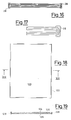
- the figure 9 shows a paper sheet, for example a letter paper sheet, indicated by the reference 20 and thus having one face 20A and one face 20B.
- a paper sheet for example a letter paper sheet, indicated by the reference 20 and thus having one face 20A and one face 20B.
- dashed lines 22 and 24 two folding lines corresponding to the common lines along which a sheet of letter paper is folded before the introduction into a normal rectangular envelope for the mailing.
- the sheet 20 is Z folded whereby for carrying out the method of the present invention the written communication to be transmitted to the addressee must be contained in the two areas 21 and 23 of the three areas (the third one being the area 25), in which these lines divide, even only ideally, the height or the greatest dimension of the sheet 20.
- the whole height of the face 20A is useful for the aforesaid written communication, whereas the address of the addressee (and possibly of the sender according to the already mentioned mode) must be written or printed on the face 20B at the areas 21 or 23.
- the present invention thus contemplates that the sheet 20, folded to the final condition of fig. 12, is glued along the four above said sides, thus defining a sealed envelope ready and suitable for mailing.
- the cover P consists of only two folded sheets, whereas in the case of the figures 16 and 17 the sheets form the cover are three and are shown in the folded and sealed condition; in that case the reference 28 indicate the glue thread or frame by which all the sheets are kept sealed together.
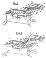
- FIG. 1 a first embodiment is shown of the apparatus according to the present invention comprising a frame 30, shown in schematic and essential form, whereby it is meant that the same, as well as the other mechanical components which will be described hereinafter, can be completed from the structural and mechanical point of view at the time of manufacturing thereof.
- a plane of operating translation is individuated for the parcels or covers to be sealed, this plane comprising a number of rollers or cylinders 32 idly mounted at their two ends; of these cylinders those indicated by the reference 32A, are placed at the four sealing stations, indicated by the references IA, IIA, IIIA e IVA, have longitudinal axes inclined with respect to the horizontal plane so as to promote the displacement of the parcel or cover being processed towards the glue applying device provided in each station.
- At least one belt 34 having it operating or upper reach passing alternatively above and under the rollers or cylinders 32 and 32A which are thus rotated by friction.
- the belt 34 forms a closed ring thanks to a transmission pulley 36 and to a driving or operating pulley 38 mounted at the end of the motor shaft of a motor 40, for example of the stepped type, which causes the pulley 38 and consequently, through the belt 34, the rollers 32 and 32A to be rotated intermittently.
- equivalent motion transmission means can be used such as for example a chain and pinion transmission mounted at the head end or at one end of the rollers or cylinders 32 and 32A, possibly externally with respectto the covertransfer plane.
- the apparatus really comprises two horizontal transfer planes for the parcels or covers to be sealed, ortogonally positioned to each other and each of which serves two sealing stations, whereby also the driving in rotation of the idle rollers or cylinders 32 and 32A takes places by means of two separated belts (one for each plane) 34, having the respective motor 40 and pulleys 36 and 38.
- a glue applying device comprising a conical head 42 monted on an axis 44 driving into rotation by controlled motor means (shown in fig. 2) comprising a motor 48 serving the two different conical heads 42 of two subsequent stations, namely IA and IIA as well as IIIA and IVA, trough a transmission comprising the two pignons 50, 52, the transmission shaft 54 and the line transmission group 56.
- Each conical head 42 is mounted so that, during the rotation, it is periodically dipped into a basin 46 containing the desidered glue in the liquid state or with a controlled fluidity; it is for example obtained in a known manner by having the basin 46 provided with suitable means for the controlled heating and termal regulation thereof.
- each conical head is mounted with a certain inclination with respect to the advancing direction of the parcels or covers, namely with respect to the line perpendicular to the adjacent transfer plane, so that the conical surface of the conical head 42 is practically almost tangent to the adjacent side of the frame.
- Each station is furthermore provided with quick drying means, represented for example by the fans 58.
- a temporary stopping member for the cover to which the glue is being applied consisting of a rod or plate journalled at one end to the frame 30 and controlled in a known manner to be displaced from a raised (or upwordly rotated) position in which permits the cover to come close with the side to be glued to the corresponding a conical head, to a lowered or stopping position, in which it prevents the cover from being displaced from the desired position during the contact with the conical head and viceversa.
- each station for the sealing by glueing is provided with a dispensing nozzle 66 connected, through a branch 68, to a conduct or suppling header 70 serving all four dispensing nozzles of the four stations and is in turn connected through a connecting duct 72 to a gear feeding pump 74, actuated from an electrical motor 76 and which draws liquid or fluidized glue 80 from a preferably thermally controlled basin 78.
- the paper is pre-glued, namely provided with a seam of glue placed long the whole perimeter of each sheet, the glue, being previously applied and dried so as to permit the different operation to which the same sheet is subjected before sealing and the mailing, is reactivated for example by applying a dosed amount of heat or of thermal energy or of energy of another suitable type, whereby it is admixed with the glue of the edges of other sheets which together that being in consideration concur to form the cover to be sent or with the glue of the other edges of the same sheet when the cover is formed by only one sheet.
- the sheet 120 is conbined with two protecting sheets, which can also be called cover sheets, 124 and 126, identical to the sheet 120 except that they are used as such, or to print thereonto only the address of addressee and the data of the sender.
- two protecting sheets which can also be called cover sheets, 124 and 126, identical to the sheet 120 except that they are used as such, or to print thereonto only the address of addressee and the data of the sender.
- the sheets 120 can be greater as to their number and in that case the sealing seam 120 extend for the whole thickness of the resulting cover.
- sealing seam 128 is reinforced by an additional member, for example a paper or tissue ribbon or another member having a similar function as it occur for example in the case of the book binding ribs for books.
- additional member for example a paper or tissue ribbon or another member having a similar function as it occur for example in the case of the book binding ribs for books.
- the sheet cover (represented by the reference numbers 130, 132 and 134, the latter acting as cover sheets) is enclosed at all its perimetral edges by a U shaped member 136, glued to the same edges of the sheets in the same manner as the sealing seam 128 of fig. 19.
- the member 136 is preferably a ribbon having a certain flexibility and previously U shaped, even if the U shape can be given to the ribbon at the time of parcel sealing.
Abstract
Description
- The present invention relates to the side sealing of covers consisting of a number of paper sheets, particularly in preparation for the mailing.
- In the following description specific reference shall be made to mail shipping parcels, it being meant that it should not be construed in limiting sense about the scope of the present invention, since the sealed covers obtained by the method and apparatus of the present invention may be provided for different uses.
- It is known that, besides the normal mailing system in which the printed material in form of sheets to be mailed is enclosed into an envelope which in turn is sealed either totally or partially at the open side for the introduction of the aforesaid printed material, in recent years different systems have been proposed and adopted expecially in connection with the exceedingly wide and capillary diffusion of the so-called continuos forms and of the fast printing, for example in laser printing centers.
- In this case, as a matter of fact, the form is also called as self-enveloping sheet and has parts which are previously glued; upon the printing is completed a folding is carried out according to predetermined folding lines and the sealing takes place preferably by activating the glue, for example by application of heat which causes the previously applied glue to be reactivated.
- In this second case, obviously, it is necessary to have suitably punched and pre-glued sheets or forms, which are useful only for specific uses: typical examples are the payment forms issued from public or private companies supplying services such as phone services, electric supply, potable water, etc.
- In these cases the requirement imposed by the public mail service, namely the accessibility to the content of the covers for the possible postal inspection (as a matter of fact these are normally mailings carried out at speciall tarif) makes it unavoidable, not only to shape the punched sheet so as to fulfill this requisite, but also use the so-called reversible glues, permitting the opening and the closing again of the cover.
- However there are several cases, which as a matter of fact are the majority, in which the printed material to be mailed consists of conventional type and size, but especially cases in which a certain number of sheets constitutes the material to be transmitted to the addressee. In this case the only solution is still that of the conventional envelope of the above mentioned type.
- A typical example is that of the transmission of the bank statements of account, which for most cases and customers, consist of a certain number of subsequent sheets. Another exmaple consists of the transmission by the aforesaid service supplying companies of the documents supporting the figures debited by the payment bills.
- This problem is particularly serious when the documents to be transmitted (for example in the typical case of the bank statements of account) is processed and printed at a very high operation rate, which in the above cited example uses computerized electrical accounting centers and laser printers operating at high speed (of the order of 80 cm/sec.); the folding along predetermined folding lines is also carried out mechanically and is made automatic: however the introduction into the envelopes causes the whole operation to be slowed down in an untolerable measure, sometimes making it almost superfluous the recourse to more and more sophisticated and fast apparatus.
- By the way and moreover the separated envelopes cause greater expenses not only owing to their intrinsic cost, but also owing to the greater weight thereby given to the covers to be mailed and which is reflected in the mailing costs which as a matter of practice and almost universally are univocally dependent on the weight of the letter to be mailed.
- Main purpose of the present invention is that of providing a solution of the aforesaid problem, which is industrially feasible and economically advantageous.
- A most specific purpose of the present invention is that of providing a method and an apparatus permitting the shipping of sealed covers without use of a separate envelope.
- These and other purposes are attained by the present invention through a method and an apparatus for the sealing of covers, particularly ready for the mail shipping.
- Thus the method according to the present invention in the most general definition thereof is characterized in that the cover to be sealed for the mailing, the edges of which are defined by at least two paper sheets or two parts of only one sheet matching to each other, is sealed by glueing along all for sides of the cover.
- According to a first embodiment of the method of the invention it contemplates the steps of (a) folding of each sheet along folding lines perpendicular to the side thereof of greatest length for a number of times such that at least two contiguous sections starting from one end of the sheet have size corresponding or consistent with those of an envelope which is usually accepted by the postal service, the other sections having size less than that of said at least to contiguous sections and (b) glueing along the four sides of the above individuated sections so that the glue involves all the sheet edges forming each of said sides, said glue being applied in situ or previously provided along all edges of the starting paper sheet, provided that in this second case the glue is of a type consistent with the handling which the sheet previously undergoes and activatable at the time of the aforesaid sealing .
- According to a second embodiment of the method of the present invention the covers to be sealed consist of an unfolded sheet of which at least the surface bearing the information to be communicated to the addressee is covered by a second sheet matching with the first one along all edges, whereafter the sealing along all sides of the thus defined cover is carried out.
- According to a modification of this second embodiment said information bearing sheet is enclosed between two protecting sheets having like size, the afore mentioned glueing along all sides being than carried out.
- According to a further embodiment of the method of the present invention said glueing along the four sides of the cover to be sealed and shippen is carried out by means of a support such as for example a ribbon coated with the sealing glue engaging with a U shaped, part the side of the cover to be sealed, said shaping being preformed in said ribbon or realized at the sealing time.
- In turn the apparatus according to the present invention for the embodiment of the above defined method comprises in its most general form means for the guided carrying of the parcels or covers of sheets to be sealed together, a number of glue sealing stations, each corresponding to one side of said parcel or cover, said station being positioned in an ordered series so that said carrying means present at each station the side for which the sealing by glueing is desired, and means each station for the sealing by glueing.
- According to a first embodiment of the apparatus of the present invention, in which the glue is applied in situ to the four sides of the packages or covers to be sealed, said carrying means consist of roll frame in which each parcel or cover to be sealed is carried on by belt or ribbon carrying means, stopping at each glue application station.
- The glue, in turn, is applied by means of conical roller applicators, drawing it from a corresponding basin containing the gluei in liquid form suitable for the application whereas downstream of each applying station there are preferably foreseen fan means for the drying of the immediately upstream applied glue.
- Alternatively, the application of the glue at each side in the corresponding station is carried out by means of glue applying nozzles, the glue being sufficiently liquid, said nozzles being fed by corresponding supplying means for the dosed supplying of glue in the afore mentioned conditions.
- In the embodiment in which the glue is not applied in situ, the sealing means consist of means for the reactivation of a thread or seam of glue previously applied to the four sides of each paper sheet so as to coat the corresponding edge of the sheet, possibly extending for a minimum distance towards the inside of the sheet.
- In this case, obviously, the reactivating means strictly depend on the type of glue:
for example if it is a glue adapted to be hot reactivated, the reactivating means are adapted to apply a dosed heat amount to the adjacent side of the cover and thus partially or totally liquify the glue which subsequently becomes solid owing to the cooling, giving place to the desired sealing effect. - According to a variation of this embodiment said thread or seam of glue, instead of the four sides of the paper sheet is applied to a ribbon like support, preferably U shaped, which is applied along the edges to be sealed, carrying then out the reactivation of the glue in the previously stated manner. In this case, by the way, the single sheet must be folded in the previously indicated manner or the parcel must contain at least one and preferably two protection sheets for the sheet (sheets) bearing the information to be transmitted to the addressee.
- As it will be appreciated from the following detailed description, the method and apparatus of the invention are based on a technique which to date has been only tested and used in the book binding field, namely to obtain a firm joint between a number of superimposed and matching sheets by coating with glue only the paper of the sheet parcel.
- As it is well known, in this manner the sheets are kept firmly together without having the glue interfering with the surface or the faces of the single sheet.
- When the sheets are to be separated from each other it is enough to apply a separation or tearing action which takes place only at the edges glued to each other, (as it occurs for example in the case of the so-called note books).
- The peculiar features and advantages of the present invention shall appear more clearly from the following detailed description, made with respect to the enclosed drawings, in which:
- figure 1 is a perspective schematic view of the apparatus according to the present invention in a first embodiment;
- figure 2 is a plan view, also necessarily schematic, of the apparatus of figure 1;
- figures 3,4,5 and 6 are views like figure 1 showing the four operating phases for the sealing of a parcel or cover of sheets.
- figures 7 and 8 are views like figures 1 and 2 respectively, showing another embodiment of the apparatus according to the invention;
- figures 9 to 15 show the different sealing operating phases referred to a paper sheet;
- figures 16 and 17 illustrate, in side view and in a partially enlarged detail view, respectively, the case of a number of sheets to be sealed in form of parcel for the mailing, and
- figures 18, 19 and 20, 21 show two particular modified embodiments of the method according to the present invention.
- For sake of clear disclosure there will be firstly commented what is shown in the figures 9 to 15, in connection with the method of the present invention.
- The figure 9 shows a paper sheet, for example a letter paper sheet, indicated by the
reference 20 and thus having oneface 20A and oneface 20B. On this sheet there are indicated bydashed lines - In the figures 10 and 11 two different manners are represented according to which the
sheet 20 may be folded along thelines - In the case represented in figure 10 the
sheet 20 is Z folded whereby for carrying out the method of the present invention the written communication to be transmitted to the addressee must be contained in the twoareas sheet 20. - In the
area 25 it will be thus written the address of the addressee and if desired that of the sender (as sometimes it is made by placing the address of the sender in the high left part of the normal envelopes). - In the case of fig. 11, on the contrary, the whole height of the
face 20A is useful for the aforesaid written communication, whereas the address of the addressee (and possibly of the sender according to the already mentioned mode) must be written or printed on theface 20B at theareas - When the movement indicated by the arrows F is completed up to have the folded sheet completely flattened, it is in both cases in the condition illustrated in figure. 12 and side wise in the condition of the figures 13 and 14 in the case of fig. 10, whereas the side view in the case of fig. 11, is that shown for sake of simplicity by the only fig. 15.
- From fig. 12 it is clearly seen that the sealing by glueing must involve the four sides I, II, III and IV.
- The present invention thus contemplates that the
sheet 20, folded to the final condition of fig. 12, is glued along the four above said sides, thus defining a sealed envelope ready and suitable for mailing. - Of course in the case of a number of sheets to be sent together, which constitutes also the case that up to date has not found a different solution apart from the use of the conventional envelope, the phases are similar except that two possibilities exist, namely that consisting in folding each sheet in the illustrated manner, and then superimposing the sheets in flattened condition carrying then out the said glueing.
- The other possibility, which is advisable especially when the sheets to be sent together are really 3 or 4, is that of having the spread sheets matching and to proceed firstly to the folding and then to the sealing of assembly of folded sheets.
- Thus, in the case of figures 14 and 15 the cover P consists of only two folded sheets, whereas in the case of the figures 16 and 17 the sheets form the cover are three and are shown in the folded and sealed condition; in that case the
reference 28 indicate the glue thread or frame by which all the sheets are kept sealed together. - Coming now to figures 1 and 2 a first embodiment is shown of the apparatus according to the present invention comprising a
frame 30, shown in schematic and essential form, whereby it is meant that the same, as well as the other mechanical components which will be described hereinafter, can be completed from the structural and mechanical point of view at the time of manufacturing thereof. - Onto the two upper surfaces the frame 30 a plane of operating translation is individuated for the parcels or covers to be sealed, this plane comprising a number of rollers or
cylinders 32 idly mounted at their two ends; of these cylinders those indicated by thereference 32A, are placed at the four sealing stations, indicated by the references IA, IIA, IIIA e IVA, have longitudinal axes inclined with respect to the horizontal plane so as to promote the displacement of the parcel or cover being processed towards the glue applying device provided in each station. - For the controlled rotation of the rollers or
cylinders belt 34 having it operating or upper reach passing alternatively above and under the rollers orcylinders - The
belt 34 forms a closed ring thanks to atransmission pulley 36 and to a driving or operatingpulley 38 mounted at the end of the motor shaft of amotor 40, for example of the stepped type, which causes thepulley 38 and consequently, through thebelt 34, therollers - By the way, instead of the
belt 34, equivalent motion transmission means can be used such as for example a chain and pinion transmission mounted at the head end or at one end of the rollers orcylinders - In fig. 1 it is observed that the apparatus really comprises two horizontal transfer planes for the parcels or covers to be sealed, ortogonally positioned to each other and each of which serves two sealing stations, whereby also the driving in rotation of the idle rollers or
cylinders respective motor 40 andpulleys - At each sealing station a glue applying device is provided comprising a
conical head 42 monted on anaxis 44 driving into rotation by controlled motor means (shown in fig. 2) comprising amotor 48 serving the two differentconical heads 42 of two subsequent stations, namely IA and IIA as well as IIIA and IVA, trough a transmission comprising the twopignons transmission shaft 54 and theline transmission group 56. - Each
conical head 42 is mounted so that, during the rotation, it is periodically dipped into abasin 46 containing the desidered glue in the liquid state or with a controlled fluidity; it is for example obtained in a known manner by having thebasin 46 provided with suitable means for the controlled heating and termal regulation thereof. - The
axis 44 of each conical head is mounted with a certain inclination with respect to the advancing direction of the parcels or covers, namely with respect to the line perpendicular to the adjacent transfer plane, so that the conical surface of theconical head 42 is practically almost tangent to the adjacent side of the frame. - In figure 2 this arrangement is clearly shown mainly as regards the position of the glue applying conical heads.
- Each station is furthermore provided with quick drying means, represented for example by the
fans 58. - It is lastly to be observed that in the shown embodiment for the mounting of the
rollers 32A in an inclined position there are alternately foreseen supportingside plates 60 andrelieved parts 62 formed onto the upper plane of theframe 30. - The operation of this embodiment is shown in the succession of it phases in the figures 3 to 7, each of which shows the parcel or cover to be sealed at a specific station. It is evident that in the real operation each station shall be operating simultaneously to the others, whereby it is sufficient to adjust the advancing speed of the
belts 34 and thus the rotation speed of the rollers orcylinders - Starting from fig. 3, the folded cover of fig. 13, generically indicated with the reference P is brought with it side I into contact with the corresponding
conical head 42 which upon rotating draws the glue from the basin and brings it upwardly until the aforesaid side I of the cpver P is moistened in a sufficient manner. - Immediately downstream the same side I undergoes the blowing action of the
fan 58 whereby during the next advancement drippings of glue from the said side are not possible. - During the downstream advancement, thanks to the inclination of the
cylinders 32A the cover P is brought with its side III into contact with the conical head of the second station and the operation is identically repeated whereafter the cover P with the two opposite side I and III already sealed passes to the stations III and IV of the apparatus, at which the application of glue onto the two other opposite side II and IV takes places. The cover P then comes out of the apparatus in a perfectly sealed and dry condition, ready for the possible stamping and the other mailing operations. It is evident that the two application operation takes adequately place independently from the thickness of the cover P thanks to the conical shape of the applying heads. - It is moreover to be observed that in the above description specifical reference has been made to single basins of glue which, however can be joined, as in the representation of the figures 1-7, in only one basin extending below the plane defined by the
frame 30, so that the conical heads can draw and apply glue under the same identical conditions of temperature and viscosity or fluidity. - In the same figures it is moreover shown for each station by the reference 64 a temporary stopping member for the cover to which the glue is being applied, this member consisting of a rod or plate journalled at one end to the
frame 30 and controlled in a known manner to be displaced from a raised (or upwordly rotated) position in which permits the cover to come close with the side to be glued to the corresponding a conical head, to a lowered or stopping position, in which it prevents the cover from being displaced from the desired position during the contact with the conical head and viceversa. - It is evident that the driving and control means for the displacement of the
member 64 between the two indicated positions have not been represented, being conventional organs within the reach of the skilled artisan, upon their function has been individuated and clarified. - Taking now into considerations the figures 7 and 8, there is shown another embodiment of the apparatus of the present invention; for sake of understanding elements which are identical or strictly similar to those of the figures 1 and 3 are indicated by the same reference number increased by 100.
- From the comparison between the figures 7 and 8 and the corresponding figures 1 and 2, it is readly appreciated the fact the the main difference resides in the manner and in the means for the application of the glue to the four sides of the cover P: as a matter of fact in the case of the figures 7 and 8 each station for the sealing by glueing is provided with a dispensing nozzle 66 connected, through a branch 68, to a conduct or suppling header 70 serving all four dispensing nozzles of the four stations and is in turn connected through a connecting duct 72 to a gear feeding pump 74, actuated from an electrical motor 76 and which draws liquid or fluidized glue 80 from a preferably thermally controlled basin 78.
- The operation of the apparatus according to this embodiment is like that already described with respect to the embodiment of figures 1-8 whereby it is not necessary to repeat detailedly the description of the operation.
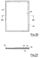
- Coming now to figures 18 and 19, they relate to a further operating solution of the method according to the present invention to which reference has been made in the preamble of the specification.
- As already mentioned, besides the direct application of the sealing glue in the processing phase of the paper sheet or sheets coming from the printing step, it is possible and foreseen by the present invention that the paper is pre-glued, namely provided with a seam of glue placed long the whole perimeter of each sheet, the glue, being previously applied and dried so as to permit the different operation to which the same sheet is subjected before sealing and the mailing, is reactivated for example by applying a dosed amount of heat or of thermal energy or of energy of another suitable type, whereby it is admixed with the glue of the edges of other sheets which together that being in consideration concur to form the cover to be sent or with the glue of the other edges of the same sheet when the cover is formed by only one sheet.
- In this case, as it is shown in the cross section view of figure 19, the
sheet 120 is conbined with two protecting sheets, which can also be called cover sheets, 124 and 126, identical to thesheet 120 except that they are used as such, or to print thereonto only the address of addressee and the data of the sender. - By the
reference 128 there is indicated and shown on enlarged scale the sealing seam which is provided all around the cover formed from the threesheets seams 122 of which eachsheet 120 is provided. - It is also foreseen and foreseable that instead of three sheets they are reduced to only two sheets, in the sense that the
sheet 120 is also acting as a cover sheet by its back face. - Of course the
sheets 120 can be greater as to their number and in that case thesealing seam 120 extend for the whole thickness of the resulting cover. - When the latter is of very great thickness it is possible and foreseen by the present invention that the
sealing seam 128 is reinforced by an additional member, for example a paper or tissue ribbon or another member having a similar function as it occur for example in the case of the book binding ribs for books. - In this connection and as a further variation (see figures 20 and 21), the sheet cover (represented by the
reference numbers member 136, glued to the same edges of the sheets in the same manner as thesealing seam 128 of fig. 19. - The
member 136 is preferably a ribbon having a certain flexibility and previously U shaped, even if the U shape can be given to the ribbon at the time of parcel sealing. - In thie above description reference is constantly made to the glues and to the glueing there being obviously meant glues suitable for paper supports.
- Since this type of glue is well known in this art (it is enough to take it into consideration the glues already used in the normal envelopes, both of reversible and of non reversible type, or those presently used for the pre-glueing of the so called self-enveloping forms) the skilled artisan shall be enabled to easily make his choice without need of particular teaching.
- Even in the case of the figures 18, 19 and 20, 21, the operations of sealing of glueing already described with respect to the previous embodiments are identically repeated, except that instead of the device for the application of liquid or fluid glue drawn from a thermally regulaed device there will be used means for the activation of the glue forming the edge seam of each sheet, such as for example conical heads as those shown in the figure 1 and 2 or even cylindrical rollers suitably heated and thermally controlled; by the way in this case the glue must be of the type which can be activated by heat.
- The invention has been described with reference to preferred embodiments thereof, it being meant that modifications and variation, which are conceptually and mechanically equivalent, are possible and foreseable without coming out of the scope thereof.
Claims (16)
- Method for the sealing of parcels or covers, consisting of at least two sheets or parts of one single sheet, tallying along their outer perimeter, characterized in that sealing is carried out by means of glueing the sheets or parts of one single sheet along all their perimetral edges.
- Method for the sealing of parcels or covers, consisting of at least one sheet folded along transversal lines for forming at least two parallel and contiguous zones according to claim 1, characterized by the steps of (a) folding of each sheet according to folding lines perpendicular to its major length side so many times that at least two contiguous zones have predetermined size starting from an edge and, the other possible zones having size less than those of said at least two contiguous zones, and (b) glueing along the four sides of the above-identified zones, so that the glue involves all sheet edges forming each of said sides.
- Method according to claim 2, characterized in that said predetermined sizes are equal to or compatible with those of envelopes for mailings.
- Method according to claim 2, characterized in that said glueing is carried out by applying the glue locally after the folding of stage (a).
- Method according to claim 1, characterized in that the cover to be sealed consist of one non-folded sheet, at least the face of which bearing the information to be communicated to the addressee is covered by a second sheet tallying with the first one along all edges, after which glueing along all sides of the so-defined cover is carried out.
- Method according to claim 5, characterized in that said sheet bearing the information is included between two protective sheets of equal sizes, and then the aforesaid glueing along all sides is effected.
- Method according to claim 1, characterized in that said glueing along the four sides of the cover to be sealed and shipped is carried out by means of a support, such as for instance a ribbon spread with the sealing glue, which engages with a U-shape the sides of the cover to be sealed, said U shape being preformed in said band or realized at the time of sealing.
- Apparatus for carrying out the method according to each of the foregoing claims, characterized by comprising means for the guided conveying of the covers or parcels of sheets to be sealed together, a plurality of sealing stations by means of glueing, each of them corresponding to one side of said cover or parcel, said stations being positioned in ordinate sequence, so that said conveying means present at each station the side for which sealing is desired by means of glueing, and sealing means at each station by means of glueing.
- Apparatus according to claim 8, characterized in that, when the glue is being locally applied at the four sides of the cover or parcel to be sealed, said conveying means consist of a plurality of rollers, on which each cover or parcel to be sealed is being moved by belt or tape conveyor means stopping in correspondence with each single station for the application of glue.
- Apparatus according to claim 9, characterized in that the glue is applied by means of conical roller heads which immerse in a corresponding small basin containing the glue in a liquid state suitable for its application, whereas downstream each conical head there are preferably provided from means for drying the glue applied immediately upstream.
- Apparatus according to claim 9, characterized in that the application of glue at each side at the corresponding station is carried out by means of nozzles dispensing sufficiently liquid glue, said nozzles being fed by feeding means of correspondingly dosed glue at the aforesaid conditions.
- Apparatus according to claim 8, characterized in that, when the glue is not being locally applied, the sealing means consist of means for the reactivation of a thread or seam of glue previously applied to the four sides of each sheet of paper, in order to coat the corresponding edge of the sheet, possibly extending by a minimum distance towards the inside of the sheet itself.
- Apparatus according to claim 12, characterized in that said reactivating means consist of a device for the application of thermical energy in a measure consistent with said thread or seam of glue.
- Apparatus according to claim 12, characterized in that said thread or seam of glue, instead of being applied to the four sides of the sheet of paper, is applied to a band support, preferably U-shaped, which is applied along the edges to be sealed, then proceeding with the reactivation of the glue, each single or the cover, comprising at least one or preferably two protective sheets of the sheet or sheets bearing the information to be transmitted to the addressee, being folded.
- Sheet of paper suitable for use in the method and in the apparatus according to claims 1,7,8,12 to 14, characterized in that it is provided along the whole perimeter with a thread or seam of glue to be activated at the time of sealing by application of a dosed energy quantity.
- Sheet of paper, according to claim 15, characterized in that said energy applied at the time of activation of said thread or seam of glue is thermical energy.
Applications Claiming Priority (2)
| Application Number | Priority Date | Filing Date | Title |
|---|---|---|---|
| ITMI911654A IT1248069B (en) | 1991-06-17 | 1991-06-17 | METHOD AND EQUIPMENT FOR SEALING POSTAL PLICHES |
| ITMI911654 | 1991-06-17 |
Publications (2)
| Publication Number | Publication Date |
|---|---|
| EP0519565A1 true EP0519565A1 (en) | 1992-12-23 |
| EP0519565B1 EP0519565B1 (en) | 1998-01-21 |
Family
ID=11360131
Family Applications (1)
| Application Number | Title | Priority Date | Filing Date |
|---|---|---|---|
| EP92201748A Expired - Lifetime EP0519565B1 (en) | 1991-06-17 | 1992-06-13 | Mail Parcel sealing method and apparatus |
Country Status (5)
| Country | Link |
|---|---|
| US (1) | US5630899A (en) |
| EP (1) | EP0519565B1 (en) |
| AT (1) | ATE162473T1 (en) |
| DE (1) | DE69224107T2 (en) |
| IT (1) | IT1248069B (en) |
Cited By (4)
| Publication number | Priority date | Publication date | Assignee | Title |
|---|---|---|---|---|
| US5575485A (en) * | 1991-11-25 | 1996-11-19 | Industrie Ilpea S.P.A. | Magnetic gasket suitable for forming a seal between a fixed part and an openable part |
| EP0812706A1 (en) * | 1996-06-14 | 1997-12-17 | Monti N.V. | Apparatus and method for producing a mailer form, in particular an envelope |
| WO1998007583A1 (en) * | 1996-08-19 | 1998-02-26 | R.C.P. Di Riccardo Consiglio | Machine and process for the automatic enveloping of messages with a variable number of sheets |
| WO1998025771A1 (en) * | 1996-12-09 | 1998-06-18 | Printed Forms Equipment Ltd. | Device for handling documents |
Families Citing this family (7)
| Publication number | Priority date | Publication date | Assignee | Title |
|---|---|---|---|---|
| CA2159542C (en) * | 1995-02-28 | 2006-01-24 | Scott A. Stevens | Method and apparatus for printing single sheet folded documents |
| US6196392B1 (en) | 1997-12-23 | 2001-03-06 | Profold, Inc. | Method and apparatus for feeding and tabbing intermixed pieces of mail |
| US6131802A (en) * | 1998-04-30 | 2000-10-17 | Lombardo; Leo | Pressure seal form |
| US6199757B1 (en) | 2000-02-01 | 2001-03-13 | Profold, Inc. | Debit card having scratch-off label strip and method of applying same |
| US6609662B2 (en) | 2000-02-01 | 2003-08-26 | Profold, Inc. | Debit card having secure scratch-off label strip with releasable layer and method of applying same |
| US6578874B1 (en) | 2000-03-13 | 2003-06-17 | Profold, Inc. | Method for correcting articles of mail and article of mail produced thereby |
| AUPR157600A0 (en) * | 2000-11-20 | 2000-12-14 | Silverbrook Research Pty. Ltd. | An apparatus and method (bin04) |
Citations (8)
| Publication number | Priority date | Publication date | Assignee | Title |
|---|---|---|---|---|
| FR375353A (en) * | 1907-03-04 | 1907-07-08 | Detroit Mailing Machine Compan | Improvements to machines for closing and stamping envelopes |
| CH247461A (en) * | 1943-07-13 | 1947-03-15 | Koenig Claus | Machine for sealing letters. |
| US3152800A (en) * | 1961-08-30 | 1964-10-13 | Pitney Bowes Inc | Handling a combination letter-envelope |
| US3981435A (en) * | 1974-01-15 | 1976-09-21 | Johnsen Edward L | Continuous business form or the like adapted for subsequent processing into combination mailing envelopes and return envelopes having a common back ply panel |
| US4091596A (en) * | 1976-05-25 | 1978-05-30 | Enmail Machine Corporation | Method of and apparatus for manufacturing envelopes |
| FR2418717A1 (en) * | 1978-03-03 | 1979-09-28 | Leysens Et G Meier Sa V | Letter form sealing machine - has transports working with glue heater and connected by device for turning form |
| US4343129A (en) * | 1976-04-27 | 1982-08-10 | G.B.R., Ltd. | Mechanism of making an envelope |
| EP0421565A2 (en) * | 1989-10-06 | 1991-04-10 | Moore Business Forms, Inc. | Pressure seal adhesive system |
Family Cites Families (11)
| Publication number | Priority date | Publication date | Assignee | Title |
|---|---|---|---|---|
| US1593148A (en) * | 1924-01-10 | 1926-07-20 | Ginn And Company | Test paper |
| US1545217A (en) * | 1924-01-10 | 1925-07-07 | Ginn And Company | Test paper |
| US1897038A (en) * | 1930-09-19 | 1933-02-14 | William C Bohmert | Binding means for paper sheets |
| US2168920A (en) * | 1938-01-31 | 1939-08-08 | Wiasmann Ludwig | Letter card |
| US3837565A (en) * | 1972-02-15 | 1974-09-24 | E Johnsen | Rapid production envelope assemblies |
| US4009071A (en) * | 1973-08-10 | 1977-02-22 | Norfin, Inc. | Sheet binding apparatus |
| US4116750A (en) * | 1977-03-15 | 1978-09-26 | Norfin, Inc. | Sheet binding apparatus |
| IT8209552A0 (en) * | 1982-11-25 | 1982-11-25 | Conti Romano | MODULE FOR POSTAL TRANSMISSION, WITH LARGE SURFACE, FOLDABLE AND SEALABLE, SUITABLE FOR BEING MADE UP OF A CONTINUOUS MODULE |
| US4817990A (en) * | 1987-09-14 | 1989-04-04 | Lee Krost Associates Inc. | Multiple value coupon system |
| US5149393A (en) * | 1989-10-26 | 1992-09-22 | Moore Business Forms, Inc. | Edge sealer for multi-ply business forms |
| US5167739A (en) * | 1991-11-21 | 1992-12-01 | Moore Business Forms, Inc. | Pressure seal multiple part |
-
1991
- 1991-06-17 IT ITMI911654A patent/IT1248069B/en active IP Right Grant
-
1992
- 1992-06-13 DE DE69224107T patent/DE69224107T2/en not_active Expired - Fee Related
- 1992-06-13 EP EP92201748A patent/EP0519565B1/en not_active Expired - Lifetime
- 1992-06-13 AT AT92201748T patent/ATE162473T1/en active
-
1995
- 1995-09-11 US US08/526,195 patent/US5630899A/en not_active Expired - Fee Related
Patent Citations (8)
| Publication number | Priority date | Publication date | Assignee | Title |
|---|---|---|---|---|
| FR375353A (en) * | 1907-03-04 | 1907-07-08 | Detroit Mailing Machine Compan | Improvements to machines for closing and stamping envelopes |
| CH247461A (en) * | 1943-07-13 | 1947-03-15 | Koenig Claus | Machine for sealing letters. |
| US3152800A (en) * | 1961-08-30 | 1964-10-13 | Pitney Bowes Inc | Handling a combination letter-envelope |
| US3981435A (en) * | 1974-01-15 | 1976-09-21 | Johnsen Edward L | Continuous business form or the like adapted for subsequent processing into combination mailing envelopes and return envelopes having a common back ply panel |
| US4343129A (en) * | 1976-04-27 | 1982-08-10 | G.B.R., Ltd. | Mechanism of making an envelope |
| US4091596A (en) * | 1976-05-25 | 1978-05-30 | Enmail Machine Corporation | Method of and apparatus for manufacturing envelopes |
| FR2418717A1 (en) * | 1978-03-03 | 1979-09-28 | Leysens Et G Meier Sa V | Letter form sealing machine - has transports working with glue heater and connected by device for turning form |
| EP0421565A2 (en) * | 1989-10-06 | 1991-04-10 | Moore Business Forms, Inc. | Pressure seal adhesive system |
Cited By (5)
| Publication number | Priority date | Publication date | Assignee | Title |
|---|---|---|---|---|
| US5575485A (en) * | 1991-11-25 | 1996-11-19 | Industrie Ilpea S.P.A. | Magnetic gasket suitable for forming a seal between a fixed part and an openable part |
| EP0812706A1 (en) * | 1996-06-14 | 1997-12-17 | Monti N.V. | Apparatus and method for producing a mailer form, in particular an envelope |
| WO1998007583A1 (en) * | 1996-08-19 | 1998-02-26 | R.C.P. Di Riccardo Consiglio | Machine and process for the automatic enveloping of messages with a variable number of sheets |
| US6266944B1 (en) | 1996-08-19 | 2001-07-31 | R.C.P. Di Riccardo Consiglio | Machine and process for the automatic enveloping of messages with a variable number of sheets |
| WO1998025771A1 (en) * | 1996-12-09 | 1998-06-18 | Printed Forms Equipment Ltd. | Device for handling documents |
Also Published As
| Publication number | Publication date |
|---|---|
| DE69224107D1 (en) | 1998-02-26 |
| IT1248069B (en) | 1995-01-05 |
| DE69224107T2 (en) | 1998-10-15 |
| ITMI911654A0 (en) | 1991-06-17 |
| EP0519565B1 (en) | 1998-01-21 |
| ITMI911654A1 (en) | 1992-12-17 |
| ATE162473T1 (en) | 1998-02-15 |
| US5630899A (en) | 1997-05-20 |
Similar Documents
| Publication | Publication Date | Title |
|---|---|---|
| US5547175A (en) | Apparatus and method for preparing mail products | |
| EP0519565A1 (en) | Mail Parcel sealing method and apparatus | |
| US5794409A (en) | Method of processing and stuffing an envelope | |
| US5107656A (en) | Assembly for producing a mass distributable printed packet | |
| US4875965A (en) | Apparatus for folding and sealing documents | |
| HU215804B (en) | Method and apparatus for producing product having folded sheets and stiffener, and product | |
| US5197262A (en) | Assembly for producing a mass distributable printed packet | |
| US20190084287A1 (en) | Corrugated cardboard plant | |
| JP2002211835A (en) | Method and device for manufacturing image product | |
| US6386771B2 (en) | Method for manufacturing mailing-ready printed products and envelopes for use with such method | |
| US5803889A (en) | Packet mailers and the methods and apparatus for making them | |
| US4021993A (en) | Apparatus for applying a wrapper | |
| US5118375A (en) | Method and apparatus for making envelopes on-line for direct mail application | |
| GB2119739A (en) | Method of gluing end flaps of a package | |
| US5294100A (en) | Method and apparatus for securing plural printed material with peelable tabs | |
| CA1300102C (en) | Document moistening device | |
| US3869330A (en) | Apparatus for applying a label to a package | |
| JP2000103194A (en) | Manufacture of printed dispatching matter, cover, method and apparatus for manufacturing cover | |
| JP4330292B2 (en) | IC card manufacturing method | |
| GB2267458A (en) | Closing device for packed product envelopes | |
| JP3657281B2 (en) | Sheet piece pasting device for spread postcards | |
| JP2517460B2 (en) | Concealed postcard manufacturing equipment | |
| JPS5925672Y2 (en) | card issuer | |
| JP4105066B2 (en) | Crimping information laminate manufacturing method and apparatus | |
| US5223076A (en) | Mechanism for assemblying and adhering sheets together |
Legal Events
| Date | Code | Title | Description |
|---|---|---|---|
| PUAI | Public reference made under article 153(3) epc to a published international application that has entered the european phase |
Free format text: ORIGINAL CODE: 0009012 |
|
| AK | Designated contracting states |
Kind code of ref document: A1 Designated state(s): AT BE CH DE DK ES FR GB GR IT LI LU MC NL PT SE |
|
| 17P | Request for examination filed |
Effective date: 19930617 |
|
| 17Q | First examination report despatched |
Effective date: 19941117 |
|
| GRAG | Despatch of communication of intention to grant |
Free format text: ORIGINAL CODE: EPIDOS AGRA |
|
| GRAH | Despatch of communication of intention to grant a patent |
Free format text: ORIGINAL CODE: EPIDOS IGRA |
|
| GRAH | Despatch of communication of intention to grant a patent |
Free format text: ORIGINAL CODE: EPIDOS IGRA |
|
| GRAH | Despatch of communication of intention to grant a patent |
Free format text: ORIGINAL CODE: EPIDOS IGRA |
|
| GRAH | Despatch of communication of intention to grant a patent |
Free format text: ORIGINAL CODE: EPIDOS IGRA |
|
| GRAA | (expected) grant |
Free format text: ORIGINAL CODE: 0009210 |
|
| AK | Designated contracting states |
Kind code of ref document: B1 Designated state(s): AT BE CH DE DK ES FR GB GR IT LI LU MC NL PT SE |
|
| PG25 | Lapsed in a contracting state [announced via postgrant information from national office to epo] |
Ref country code: NL Free format text: LAPSE BECAUSE OF FAILURE TO SUBMIT A TRANSLATION OF THE DESCRIPTION OR TO PAY THE FEE WITHIN THE PRESCRIBED TIME-LIMIT Effective date: 19980121 Ref country code: LI Free format text: LAPSE BECAUSE OF FAILURE TO SUBMIT A TRANSLATION OF THE DESCRIPTION OR TO PAY THE FEE WITHIN THE PRESCRIBED TIME-LIMIT Effective date: 19980121 Ref country code: GR Free format text: LAPSE BECAUSE OF FAILURE TO SUBMIT A TRANSLATION OF THE DESCRIPTION OR TO PAY THE FEE WITHIN THE PRESCRIBED TIME-LIMIT Effective date: 19980121 Ref country code: ES Free format text: THE PATENT HAS BEEN ANNULLED BY A DECISION OF A NATIONAL AUTHORITY Effective date: 19980121 Ref country code: CH Free format text: LAPSE BECAUSE OF FAILURE TO SUBMIT A TRANSLATION OF THE DESCRIPTION OR TO PAY THE FEE WITHIN THE PRESCRIBED TIME-LIMIT Effective date: 19980121 Ref country code: BE Free format text: LAPSE BECAUSE OF FAILURE TO SUBMIT A TRANSLATION OF THE DESCRIPTION OR TO PAY THE FEE WITHIN THE PRESCRIBED TIME-LIMIT Effective date: 19980121 Ref country code: AT Free format text: LAPSE BECAUSE OF FAILURE TO SUBMIT A TRANSLATION OF THE DESCRIPTION OR TO PAY THE FEE WITHIN THE PRESCRIBED TIME-LIMIT Effective date: 19980121 |
|
| REF | Corresponds to: |
Ref document number: 162473 Country of ref document: AT Date of ref document: 19980215 Kind code of ref document: T |
|
| REG | Reference to a national code |
Ref country code: CH Ref legal event code: EP |
|
| REF | Corresponds to: |
Ref document number: 69224107 Country of ref document: DE Date of ref document: 19980226 |
|
| ITF | It: translation for a ep patent filed |
Owner name: ABM AGENZIA BREVETTI & MARCHI |
|
| PG25 | Lapsed in a contracting state [announced via postgrant information from national office to epo] |
Ref country code: SE Free format text: LAPSE BECAUSE OF FAILURE TO SUBMIT A TRANSLATION OF THE DESCRIPTION OR TO PAY THE FEE WITHIN THE PRESCRIBED TIME-LIMIT Effective date: 19980421 Ref country code: PT Free format text: LAPSE BECAUSE OF FAILURE TO SUBMIT A TRANSLATION OF THE DESCRIPTION OR TO PAY THE FEE WITHIN THE PRESCRIBED TIME-LIMIT Effective date: 19980421 Ref country code: DK Free format text: LAPSE BECAUSE OF FAILURE TO SUBMIT A TRANSLATION OF THE DESCRIPTION OR TO PAY THE FEE WITHIN THE PRESCRIBED TIME-LIMIT Effective date: 19980421 |
|
| ET | Fr: translation filed | ||
| PG25 | Lapsed in a contracting state [announced via postgrant information from national office to epo] |
Ref country code: LU Free format text: LAPSE BECAUSE OF NON-PAYMENT OF DUE FEES Effective date: 19980613 Ref country code: GB Free format text: LAPSE BECAUSE OF NON-PAYMENT OF DUE FEES Effective date: 19980613 |
|
| NLV1 | Nl: lapsed or annulled due to failure to fulfill the requirements of art. 29p and 29m of the patents act | ||
| REG | Reference to a national code |
Ref country code: CH Ref legal event code: PL |
|
| PLBE | No opposition filed within time limit |
Free format text: ORIGINAL CODE: 0009261 |
|
| STAA | Information on the status of an ep patent application or granted ep patent |
Free format text: STATUS: NO OPPOSITION FILED WITHIN TIME LIMIT |
|
| PG25 | Lapsed in a contracting state [announced via postgrant information from national office to epo] |
Ref country code: MC Free format text: LAPSE BECAUSE OF NON-PAYMENT OF DUE FEES Effective date: 19981231 |
|
| 26N | No opposition filed | ||
| GBPC | Gb: european patent ceased through non-payment of renewal fee |
Effective date: 19980613 |
|
| PG25 | Lapsed in a contracting state [announced via postgrant information from national office to epo] |
Ref country code: FR Free format text: LAPSE BECAUSE OF NON-PAYMENT OF DUE FEES Effective date: 19990226 |
|
| PG25 | Lapsed in a contracting state [announced via postgrant information from national office to epo] |
Ref country code: DE Free format text: LAPSE BECAUSE OF NON-PAYMENT OF DUE FEES Effective date: 19990401 |
|
| REG | Reference to a national code |
Ref country code: FR Ref legal event code: ST |
|
| PG25 | Lapsed in a contracting state [announced via postgrant information from national office to epo] |
Ref country code: IT Free format text: LAPSE BECAUSE OF NON-PAYMENT OF DUE FEES;WARNING: LAPSES OF ITALIAN PATENTS WITH EFFECTIVE DATE BEFORE 2007 MAY HAVE OCCURRED AT ANY TIME BEFORE 2007. THE CORRECT EFFECTIVE DATE MAY BE DIFFERENT FROM THE ONE RECORDED. Effective date: 20050613 |