EP0511089A1 - Cigar lighter, especially for motor vehicles - Google Patents
Cigar lighter, especially for motor vehicles Download PDFInfo
- Publication number
- EP0511089A1 EP0511089A1 EP92401131A EP92401131A EP0511089A1 EP 0511089 A1 EP0511089 A1 EP 0511089A1 EP 92401131 A EP92401131 A EP 92401131A EP 92401131 A EP92401131 A EP 92401131A EP 0511089 A1 EP0511089 A1 EP 0511089A1
- Authority
- EP
- European Patent Office
- Prior art keywords
- plug
- cigar lighter
- circuit breaker
- lighter according
- current plug
- Prior art date
- Legal status (The legal status is an assumption and is not a legal conclusion. Google has not performed a legal analysis and makes no representation as to the accuracy of the status listed.)
- Granted
Links
Images


Classifications
-
- F—MECHANICAL ENGINEERING; LIGHTING; HEATING; WEAPONS; BLASTING
- F23—COMBUSTION APPARATUS; COMBUSTION PROCESSES
- F23Q—IGNITION; EXTINGUISHING-DEVICES
- F23Q7/00—Incandescent ignition; Igniters using electrically-produced heat, e.g. lighters for cigarettes; Electrically-heated glowing plugs
-
- B—PERFORMING OPERATIONS; TRANSPORTING
- B60—VEHICLES IN GENERAL
- B60N—SEATS SPECIALLY ADAPTED FOR VEHICLES; VEHICLE PASSENGER ACCOMMODATION NOT OTHERWISE PROVIDED FOR
- B60N3/00—Arrangements or adaptations of other passenger fittings, not otherwise provided for
- B60N3/14—Arrangements or adaptations of other passenger fittings, not otherwise provided for of electrically-heated lighters
-
- B—PERFORMING OPERATIONS; TRANSPORTING
- B60—VEHICLES IN GENERAL
- B60Q—ARRANGEMENT OF SIGNALLING OR LIGHTING DEVICES, THE MOUNTING OR SUPPORTING THEREOF OR CIRCUITS THEREFOR, FOR VEHICLES IN GENERAL
- B60Q3/00—Arrangement of lighting devices for vehicle interiors; Lighting devices specially adapted for vehicle interiors
- B60Q3/20—Arrangement of lighting devices for vehicle interiors; Lighting devices specially adapted for vehicle interiors for lighting specific fittings of passenger or driving compartments; mounted on specific fittings of passenger or driving compartments
- B60Q3/275—Smoking-related fittings, e.g. cigarette lighters or ashtrays
-
- B—PERFORMING OPERATIONS; TRANSPORTING
- B60—VEHICLES IN GENERAL
- B60Q—ARRANGEMENT OF SIGNALLING OR LIGHTING DEVICES, THE MOUNTING OR SUPPORTING THEREOF OR CIRCUITS THEREFOR, FOR VEHICLES IN GENERAL
- B60Q3/00—Arrangement of lighting devices for vehicle interiors; Lighting devices specially adapted for vehicle interiors
- B60Q3/60—Arrangement of lighting devices for vehicle interiors; Lighting devices specially adapted for vehicle interiors characterised by optical aspects
- B60Q3/62—Arrangement of lighting devices for vehicle interiors; Lighting devices specially adapted for vehicle interiors characterised by optical aspects using light guides
- B60Q3/64—Arrangement of lighting devices for vehicle interiors; Lighting devices specially adapted for vehicle interiors characterised by optical aspects using light guides for a single lighting device
Landscapes
- Engineering & Computer Science (AREA)
- Mechanical Engineering (AREA)
- Chemical & Material Sciences (AREA)
- Combustion & Propulsion (AREA)
- General Engineering & Computer Science (AREA)
- Transportation (AREA)
- Passenger Equipment (AREA)
- Coupling Device And Connection With Printed Circuit (AREA)
Abstract
Description
La présente invention concerne un allume-cigares, notamment pour véhicule automobile du genre comportant, d'une part, une fiche de courant, et d'autre part, pour réception de ladite fiche de courant, un corps creux d'allumage, formant prise de courant, pourvu d'une pièce élastique de contact électrique et de languettes d'alimentation électriques.The present invention relates to a cigarette lighter, in particular for a motor vehicle of the type comprising, on the one hand, a current plug, and on the other hand, for reception of said current plug, a hollow ignition body, forming an outlet current, provided with an elastic piece of electrical contact and electrical supply tabs.
Cette fiche peut consister en une prise de courant pour alimenter notamment un accessoire, tel qu'une lampe d'éclairage, ou en variante en un bouchon de chauffage recevant un corps de chauffage pour allumage d'un cigare ou d'une cigarette.This plug may consist of a socket to supply in particular an accessory, such as a lighting lamp, or alternatively in a heating plug receiving a heating body for lighting a cigar or a cigarette.
Jusqu'à présent, la prise de courant et le bouchon n'étaient pas à l'image l'un de l'autre. En effet, un bouchon comporte usuellement une partie fixe et une partie mobile à l'encontre d'un ressort de rappel, ladite partie mobile portant une coupelle d'extrémité pour, après déplacement de ladite coupelle, en position de chauffage, coopération avec ladite pièce élastique sous forme d'un bilame, dont les lames s'incurvent vers l'extérieur au fur et à mesure que celui-ci s'échauffe, jusqu'à désenclenchement de la coupelle sous l'action du ressort de rappel porté par le bouchon.Until now, the socket and the plug were not the image of each other. Indeed, a plug usually comprises a fixed part and a mobile part against a return spring, said mobile part carrying an end cup for, after displacement of said cup, in the heating position, cooperation with said elastic part in the form of a bimetallic strip, the blades of which curve outwards as it heats up, until the cup disengages under the action of the return spring carried by the plug.
Dans une prise de courant par contre il n'y a pas de partie mobile manoeuvrable par l'usager, la prise prenant appui, pour son alimentation, sur l'organe de fixation du bilame. Usuellement, des moyens de retenue interviennent entre ledit corps d'allumage et la fiche pour maintien de celle-ci en position inactive, lesdits moyens étant portés en partie par une pièce de guidage appartenant à ladite fiche et en partie par ledit corps.In an electrical outlet, on the other hand, there is no mobile part which can be maneuvered by the user, the socket being supported, for its supply, on the fixing member of the bimetallic strip. Usually, retaining means intervene between said ignition body and the plug to maintain the latter in the inactive position, said means being carried in part by a guide piece belonging to said plug and in part by said body.
On a déjà proposé dans la demande FR 91 00501 déposée le 19 janvier 1991 et non publiée à ce jour, une disposition avec un dispositif de protection contre les surchauffes, inséré dans le circuit d'alimentation de l'allume-cigares, sous forme d'un disjoncteur thermique réarmable ayant un coefficient de température positif permanent, avec une résistance augmentant avec la température.
On peut utiliser, comme disjoncteur, un composant à base de polymère semi-conducteur vendu par la société "RAYCHEM" sous la marque "PolySwitch". Grâce à cela, en cas de surchauffes, par exemple, lorsque la coupelle reste coincée dans le bilame, le disjoncteur thermique passe très rapidement d'une très basse résistance à une résistance élevée, lorsque consécutivement à une surintensité ou une surchauffe sa température dépasse un certain seuil.It is possible to use, as a circuit breaker, a component based on a semiconductor polymer sold by the company "RAYCHEM" under the brand name "PolySwitch". Thanks to this, in the event of overheating, for example, when the cup remains stuck in the bimetallic strip, the thermal circuit breaker very quickly passes from a very low resistance to a high resistance, when following an overcurrent or an overheating its temperature exceeds a certain threshold.
Lorsque la surintensité ou la température sont substantiellement réduites ou éliminées, le composant se refroidit et retrouve, après extraction de la fiche, sa faible résistance.When the overcurrent or the temperature are substantially reduced or eliminated, the component cools and regains, after extraction from the plug, its low resistance.
L'allume-cigares revient donc opérationnel, sans qu'il soit nécessaire de remplacer un quelconque composant, notamment des fusibles de protection associés à l'allume-cigares.The cigarette lighter therefore comes back operational, without the need to replace any component, in particular protective fuses associated with the cigar lighter.
La Demanderesse s'est demandée s'il n'était pas possible de tirer un nouveau parti de ce disjoncteur thermique, pour simplifier le bouchon en vue de rendre celui-ci semblable à une prise de courant c'est-à-dire dépourvu de partie mobile.The Applicant wondered if it was not possible to take advantage of this thermal circuit breaker again, to simplify the plug in order to make it similar to an electrical outlet, that is to say devoid of mobile part.
La présente invention a pour but de satisfaire ce souhait.The present invention aims to satisfy this wish.
Suivant l'invention, un allume-cigares du type sus-indiqué est caractérisé en ce que lesdits moyens de retenue sont conformés pour retenir en position active la fiche de courant, et en ce que ladite fiche de courant est dépourvue de partie mobile l'une par rapport à l'autre.According to the invention, a cigar lighter of the above-mentioned type is characterized in that said retaining means are shaped to retain the current plug in the active position, and in that said current plug has no movable part. one in relation to the other.
Ainsi, grâce à l'invention, la prise de courant et le bouchon sont à l'image l'un de l'autre, et on est sûr par exemple que le bouchon de chauffage et le corps d'allumage ne chaufferont pas outre mesure, compte tenu du disjoncteur thermique réarmable, qui a ainsi une deuxième fonction, ledit disjoncteur coupant l'alimentation de la résistance chauffante du bouchon, lorsque celle-ci atteint la température désirée.Thus, thanks to the invention, the socket and the plug are in the image of each other, and we are sure for example that the heating plug and the body ignition will not overheat, taking into account the resettable thermal circuit breaker, which thus has a second function, said circuit breaker cutting the power to the heating resistance of the plug, when the latter reaches the desired temperature.
En outre le bouchon ne comporte que des pièces statiques, ce qui simplifie celui-ci, augmente sa fiabilité et sa robustesse, tout en simplifiant les problèmes de réglage et en diminuant l'encombrement axial de l'allume-cigares.In addition, the plug has only static parts, which simplifies it, increases its reliability and robustness, while simplifying adjustment problems and reducing the axial size of the cigar lighter.
De plus, grâce notamment à la conformation des moyens de retenue et à la position statique de la résistance chauffante par rapport à la pièce de guidage, les côtés à respecter pour que le bouchon puisse coopérer avec la pièce élastique sont aisément réalisables. Il en est de même en ce qui concerne la prise de courant.In addition, thanks in particular to the shape of the retaining means and to the static position of the heating resistor relative to the guide piece, the sides to be observed so that the plug can cooperate with the elastic piece are easily achievable. The same applies to the socket.
Tout ceci ouvre la voie à un grand nombre de développement. Ainsi, suivant une caractéristique, le corps d'allumage est dépourvu de bilame, sa pièce élastique de contact électrique servant uniquement de pièce de contact au bénéfice du coût de fabrication et des problèmes de réglage, les lames de ladite pièce n'ayant plus à s'incurver.All this opens the way to a large number of developments. Thus, according to one characteristic, the ignition body does not have a bimetallic strip, its elastic electrical contact part serving only as a contact part for the benefit of the manufacturing cost and adjustment problems, the blades of said part no longer having to bend.
Suivant une autre caractéristique, les moyens de retenue comportent des languettes d'accrochage appartenant à l'un des éléments corps d'allumage - fiche de courant et deux gorges échelonnées axialement appartenant à l'autre desdits éléments fiche de courant - corps d'allumage.According to another characteristic, the retaining means comprise latching tabs belonging to one of the ignition body - plug plug elements and two axially staggered grooves belonging to the other of said plug plug - ignition plug elements .
Avantageusement les gorges sont formées dans la fiche de courant et les languettes dans le corps d'allumage, de manière connue en soi, mais lesdites languettes sont alors dirigées vers l'extrémité ouverte du corps d'allumage au bénéfice d'une réduction de l'encombrement axial de l'allume-cigares.Advantageously, the grooves are formed in the current plug and the tongues in the ignition body, in a manner known per se, but said tongues are then directed towards the open end of the ignition body for the benefit of a reduction of 1 axial dimension of the cigarette lighter.
Avantageusement, les gorges sont formées dans la pièce de guidage du bouchon et celle-ci entoure en partie une pièce creuse de prise de courant fixée à isolation électrique à ladite pièce de guidage.Advantageously, the grooves are formed in the guide piece of the plug and the latter partially surrounds a hollow socket-outlet piece fixed with electrical insulation to said guide piece.
Avantageusement cette pièce fait saillie axialement par rapport à ladite pièce de guidage. Ainsi dans le cas d'une fiche de courant sous la forme d'un bouchon, cette pièce forme pare-cendres.Advantageously, this part projects axially with respect to said guide part. Thus, in the case of a current plug in the form of a plug, this part forms an ash barrier.
On appréciera dans tous les cas que cette configuration permet une standardisation bouchon - prise de courant, les mêmes pièces étant utilisées dans les deux cas.It will be appreciated in all cases that this configuration allows plug-socket standardization, the same parts being used in both cases.
Grâce au disjoncteur thermique et en utilisant ses propriétés de résistance électrique, on peut insérer celui-ci dans un circuit électrique comportant des moyens d'avertissement avec au moins une lampe d'éclairage pour la fiche et faire varier l'éclairage de celle-ci pour avertir l'usager par exemple lorsque le bouchon est chaud.Thanks to the thermal circuit breaker and using its electrical resistance properties, it can be inserted into an electrical circuit comprising warning means with at least one lighting lamp for the plug and to vary the lighting thereof. to warn the user for example when the cap is hot.
Les moyens d'avertissement peuvent comporter également une sonnette mise en action lorsque le disjoncteur sautera, ou un autre dispositif sonore tel que buzzer ou une sirène.The warning means can also include a bell activated when the circuit breaker blows, or another sound device such as a buzzer or a siren.
Avantageusement, les moyens d'avertissement sont montés en parallèle par rapport au disjoncteur thermique pour faire sentir pleinement leurs effets en fin de chauffage du bouchon.Advantageously, the warning means are mounted in parallel with respect to the thermal circuit breaker to make their effects fully felt at the end of heating of the plug.
La description qui va suivre illustre l'invention en référence aux dessins annexés dans lesquels:
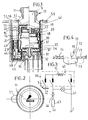
- la figure 1 est une vue en coupe axiale d'un allume-cigares selon l'invention avec en partie gauche le bouchon en position inactive et dans en partie gauche le bouchon en position active;
- la figure 2 est une vue de dessus du bouchon de la figure 1;
- la figure 3 est une vue schématique du circuit électrique d'alimentation de l'allume-cigares selon l'invention;
- la figure 4 est une vue partielle montrant une partie des moyens de montage du bouton du bouchon à la pièce de guidage selon l'invention;
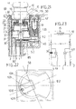
- les figures 5 à 7 sont des vues analogues aux figures 1 à 3, pour un second exemple de réalisation selon l'invention, le bouchon étant en position inactive dans la figure 5;
- la figure 8 est une vue analogue à la figure 5, pour ce second exemple de réalisation, le bouchon n'étant pas coupé et étant représenté en positions active et inactive;
- la figure 9 est une vue de dessous de la figure 8 montrant la partie connectrice de l'allume-cigares;
- la figure 10 est une vue de dessus selon la figure 8 montrant la conformation de la planche de bord du véhicule;
- la figure 11 est une vue analogue à la figure 5 avec une rotation de 90° par rapport à celle-ci;
- la figure 12 est une vue de dessus selon la figure 11;
- la figure 13 est une vue de dessous montrant la partie connectrice d'un corps d'allumage pour un troisième exemple de réalisation;
- la figure 14 est une vue en coupe du corps d'allumage pour ce troisième exemple de réalisation;
- la figure 15 est une vue en coupe montrant une prise de courant selon l'invention;
- la figure 16 est une vue de dessus selon la figure 15, la partie supérieure de la prise étant otée;
- la figure 17 représente la courbe caractéritisque du disjoncteur thermique, avec en ordonnée la valeur de la résistance, et en abscisse la température;
- la figure 18 est une vue en coupe axiale d'un allume cigare pour un quatrième exemple de réalisation;
- la figure 19 est une vue de dessous selon la figure 18 sans le corps d'allumage;
- la figure 20 est une vue de dessus selon la figure 18 sans le corps d'allumage;
- la figure 21 est une vue en coupe axiale analogue à la figure 18, avec représentation de l'excroissance;
- la figure 22 est une vue de dessus selon la figure 18 montrant les trous pratiqués dans la paroi du véhicule;
- la figure 23 est un schéma électrique des figures 18 à 22.
- Figure 1 is an axial sectional view of a cigarette lighter according to the invention with the plug in the left part in the inactive position and in the left part the plug in the active position;
- Figure 2 is a top view of the cap of Figure 1;
- Figure 3 is a schematic view of the electric circuit supplying the cigarette lighter according to the invention;
- FIG. 4 is a partial view showing part of the means for mounting the button of the plug to the guide piece according to the invention;
- Figures 5 to 7 are views similar to Figures 1 to 3, for a second embodiment of the invention, the plug being in the inactive position in Figure 5;
- Figure 8 is a view similar to Figure 5, for this second embodiment, the plug is not cut and being shown in active and inactive positions;
- Figure 9 is a bottom view of Figure 8 showing the connecting part of the cigarette lighter;
- Figure 10 is a top view according to Figure 8 showing the shape of the vehicle dashboard;
- Figure 11 is a view similar to Figure 5 with a rotation of 90 ° relative thereto;
- Figure 12 is a top view according to Figure 11;
- Figure 13 is a bottom view showing the connecting part of an ignition body for a third embodiment;
- Figure 14 is a sectional view of the ignition body for this third embodiment;
- Figure 15 is a sectional view showing an outlet according to the invention;
- Figure 16 is a top view according to Figure 15, the upper part of the socket being removed;
- FIG. 17 represents the characteristic curve of the thermal circuit breaker, with the value of the resistance on the ordinate, and the temperature on the abscissa;
- Figure 18 is an axial sectional view of a cigarette lighter for a fourth embodiment;
- Figure 19 is a bottom view according to Figure 18 without the ignition body;
- Figure 20 is a top view according to Figure 18 without the ignition body;
- Figure 21 is an axial sectional view similar to Figure 18, with representation of the protrusion;
- Figure 22 is a top view according to Figure 18 showing the holes in the wall of the vehicle;
- FIG. 23 is an electrical diagram of FIGS. 18 to 22.
Dans les figures est illustré un allume-cigares pour véhicule automobile comportant, d'une part, une fiche de courant 10,100,200 et, d'autre part, pour réception de ladite fiche, un corps creux d'allumage 30,300,310, formant prise de courant, pourvu d'une pièce élastique de contact électrique 37, de languettes d'alimentation électriques 1,2,3.In the figures is illustrated a cigar lighter for a motor vehicle comprising, on the one hand, a current plug 10,100,200 and, on the other hand, for receiving said plug, a hollow ignition body 30,300,310, forming an electrical outlet, provided with an elastic
Des moyens de retenue 20 interviennent entre ledit corps et ladite fiche, pour maintien de celle-ci en position inactive, lesdits moyens 20 étant portés en partie par une pièce de guidage 13 appartenant à ladite fiche, et en partie par ledit corps d'allumage.Retaining means 20 intervene between said body and said plug, to maintain the latter in the inactive position, said means 20 being carried in part by a
Dans le circuit électrique de cet allume-cigares, est inséré un disjoncteur thermique réarmable 34, par exemple à base de polymère semi-conducteur, ayant un coefficient de température positif permanent avec une résistance augmentant avec la température.In the electrical circuit of this cigar lighter, a resettable
En variante, le disjoncteur 34 a coefficient de température positif peut être en céramique à base de titanate de baryum.As a variant, the
Suivant l'invention, les moyens de retenue 20 sont conformés pour retenir en position active la fiche de courant 10,100,200, et ladite fiche 10,100,200 est dépourvue de partie mobile l'une par rapport à l'autre.According to the invention, the retaining means 20 are shaped to retain the plug in the active position of current 10,100,200, and said plug 10,100,200 is devoid of movable part relative to each other.
Dans les figures 1 à 14 et 18 à 23, la fiche est un bouchon d'allumage 10,100, tandis que dans les figures 15 et 16 ladite fiche consiste en une prise de courant.In Figures 1 to 14 and 18 to 23, the plug is a 10,100 ignition plug, while in Figures 15 and 16 said plug consists of an outlet.
Grâce à l'invention, de manière décrite ci-après, ledit bouchon et ladite prise comportent des éléments standards, et dans la description qui va suivre, l'expression "position active" signifie que le circuit électrique de l'allume-cigares est établit, ladite prise ou ledit bouchon étant alimentés électriquement, tandis que l'expression "position inactive" signifie que ledit bouchon et ladite prise ne sont pas alimentés électriquement. Ainsi, en position active, la fiche de courant est admise à coopérer avec la pièce de contact 37, pour fermeture du circuit électrique de l'allume-cigares, tandis qu'en position inactive ladite fiche est à distance de ladite pièce 37, le circuit électrique étant alors ouvert.Thanks to the invention, as described below, said plug and said socket include standard elements, and in the description which follows, the expression "active position" means that the electric circuit of the cigar lighter is establishes, said plug or said plug being electrically powered, while the expression "inactive position" means that said plug and said plug are not electrically powered. Thus, in the active position, the current plug is allowed to cooperate with the
Pour ce faire, la fiche présente une pièce de prise de courant 14 propre à coopérer avec la pièce élastique 37. Cette pièce 14, ici sous forme de cuvette 14, est solidaire de manière statique de la pièce de guidage 13.To do this, the plug has a
Plus précisément dans les figures 1 à 4, l'allume-cigares comporte, d'une part, un bouchon amovible 10, formant une fiche de courant, pourvu d'une cuvette d'extrémité 14 recevant un corps ou résistance électrique de chauffage 15 destiné à allumer une cigarette ou un cigare, et, d'autre part, un corps d'allumage creux 30, formant prise de courant, pourvu d'une pièce élastique de contact électrique 37 et de languettes d'alimentation électriques 1 à 3. Le corps 30 est en matériau électriquement conducteur, ici en tôle, et est obtenu par emboutissage.More precisely in FIGS. 1 to 4, the cigar lighter comprises, on the one hand, a
Le bouchon 10 se loge à coulissement à l'intérieur du corps 30 et est propre à occuper une position active (allume-cigares branché), une position inactive (allume-cigares débranché) et à être extrait. Pour ce faire, le bouchon 10 présente un bouton de préhension 11,9,12 accessible à l'usager.The
Dans les positions active et inactive, le bouchon 10 est enfoncé dans le corps 30, et est retenu dans ces positions par des languettes d'accrochage 21 d'orientation axiale, dotées chacune à leur extrémité libre d'un crochet de retenue en forme de V, issues du corps d'allumage 30 et par des gorges 22 échelonnées axialement pratiquées dans la pièce de guidage 13, que présente le bouchon 10. Ici deux languettes 21 diamétralement opposées sont prévues.In the active and inactive positions, the
Le bouchon 10 comporte outre la cuvette 14, des rondelles d'isolation électriques 19,18, un rivet de fixation 17, la résistance 15, un chapeau 11 en matière plastique, tel que du polyamide noir, en matière non translucide, une partie 9 en matière translucide, tel que du polycarbonate de couleur cristal, et une bague éclairante 12 en matière translucide, tel que du polycarbonate de couleur rouge, des moyens d'assemblage 16 étant prévus entre la partie 9 et la pièce 13.The
Le corps d'allumage 30 est creux en étant de forme cylindrique, pour réception du bouchon 10 de forme cylindrique complémentaire. Ce corps 30 présente un fond 31 et une extrémité ouverte avec une collerette d'extrémité. Ce corps présente également deux trous 24 (figure 11) pour coopération avec des crochets élastiques issus de la planche de bord 50 du véhicule ou d'une paroi de celui-ci, tel qu'une console.The
Cette planche de bord 50 est creusée pour réception du corps d'allumage 30 et présente une paroi avec une base formant partie connectrice. Cette paroi présente également une excroissance pour logement d'une excroissance 51 de logement d'une lampe d'éclairage 41 solidaire du corps 30.This
Ce corps 30 présente également une jupe cylindrique dans laquelle sont découpées les languettes 21 dirigées vers l'extrémité ouverte dudit corps électriquement conducteur. Le fond 31 porte à isolation électrique, par l'intermédiaire d'une première pièce électriquement isolante 32 et d'une seconde pièce électriquement isolante 33, la pièce de contact 37, formant pièce d'accrochage.This
Le fond 31 porte des languettes d'alimentation électriques 1,2,3 s'étendant globalement axialement à l'extérieur du corps 30 en étant ici globalement en forme d'équerre avec chacune une base parallèle au fond 31.The bottom 31 carries
La pièce 37 est en matériau électriquement conducteur et est montée à l'intérieur du corps 30 sur la pièce 33 dotée pour ce faire à son extrémité libre d'une collerette de centrage. La pièce 37, ici métallique, est en forme de U avec deux lames axiales, ici légèrement inclinées, globalement diamétralement opposées pourvues chacune d'un bec d'extrémité, pour contact ponctuel par pincement avec la cuvette 14 du bouchon 10. Les lames de la pièce 37 s'étendent dans le même sens que les languettes 21.The
Le fond de la pièce 33 est creusé pour logement de la base de la pièce 37 et immobilisation en rotation de celle-ci par coopération de formes.The bottom of the
Un organe de fixation 36, ici une vis électriquement conductrice ou en variante un rivet, s'appuie par sa tête sur une rondelle d'application 35 conductrice. Cet organe 36 traverse la pièce 33, le fond 31, la pièce 32, qui sont tous troués à cet effet, et est fixé par vissage à la base de la languette 1 dotée d'un trou fileté à cet effet.A fixing
La pièce 32 est creusée pour immobilisation par coopération de formes de la base de la languette 1. Elle présente des cheminées pour montage des autres languettes 2,3, ladite languette 3 ayant une forme sinueuse.The
La pièce 33 présente un téton traversant le fond 31 et servant de centreur à la base de la languette 2 au contact du fond 31. Les pièces 32 et 33 sont immobilisées l'une par rapport à l'autre par coopération de formes.The
Ainsi la vis 36 sert de fixation aux susmentionnées pièces, avec blocage en rotation de celle-ci par coopération de formes. La pièce 33 présente également une autre collerette de centrage pour montage isolant des pièces 34,35.Thus the
On notera que les languettes 21 axiales ont une extrémité libre qui s'étend au-dessus de la pièce 37, la languette 2 étant connectée à la borne négative du véhicule (la masse de celui-ci) ainsi que le corps 30, tandis que les languettes 1,3 sont reliées à la borne positive de la batterie.It will be noted that the
Ici, la languette 1 est connectée à l'alimentation de l'antivol, tandis que la languette 3 est connectée aux lanternes du véhicule.Here, the
Les parties 9,11,12 du bouton du bouchon 10 sont attelées de manière statique à la pièce de guidage 13. Cette pièce 13 consiste ici en une cuvette creuse avec une jupe annulaire propre à coopérer avec la jupe du corps 30, la jupe de la cuvette 13 présentant deux gorges échelonnées axialement 22.The
La cuvette de guidage 13 entoure la cuvette d'alimentation électrique 14, lesdites cuvettes étant de forme cylindrique en étant isolée électriquement par la rondelle 19 interposée entre celles-ci. La cuvette 14 présente une zone cylindrique de contact 23 à son extrémité libre et fait saillie axialement par rapport à l'extrémité libre de la cuvette 13. Ainsi, les tolérances de fabrication n'ont pas à être précisées.The
On appréciera que les cuvettes 13,14 de forme annulaire sont robustes. Elles sont en matériau électriquement conducteur, ici en tôle, en étant obtenues par emboutissage.It will be appreciated that the
La partie opaque 11 est creuse et sert de logement à la partie 9 translucide avec assemblage desdites pièces par clipsage. Le fond de la pièce 11 est doté d'une fenêtre d'éclairage avec un sigle d'allume-cigares (figure 2) pour éclairage de celui-ci, grâce au corps 9.The
La partie 12, sous forme d'une bague, est fixée également par clipsage à la partie 11 (à l'extrémité libre de celui-ci) et forme une collerette. La partie 9 est assemblée en final à la cuvette 13 par un montage 16 du type baïonnette. Ainsi les cuvettes 13 et 14 peuvent être fixées l'une par rapport à l'autre par avance.
Pour cela le fond de la cuvette 13 présente trois ouvertures 72 oblongues et la pièce 9 trois pattes 73 à ailes latérales bombées 70 et talon de retenue 71. Ainsi le montage se fait par enfilage des pattes 73 et ailes 70 à travers les ouvertures 72 dimensionnées à cet effet, puis par rotation, l'aile 70 prenant appui sur la face du fond de la coupelle 13 tournée vers l'extérieur, tandis que le talon 71 descend dans le trou 72.For this, the bottom of the
Il y a ainsi immobilisation axiale et en rotation du corps 9 par rapport à la cuvette 13, avec une bonne tenue de la liaison en température. En variante, on peut prévoir une fixation par collage, vissage ou analogue.There is thus axial immobilization and rotation of the
La cuvette 14 présente un fond percé pour passage de l'organe de fixation 17. Autour de l'organe 17 sont montées des rondelles isolantes 18,19, la rondelle 19 étant en contact avec le fond de la coupelle 13.The
Le corps de chauffage 15 consiste en une résistance électrique avec un fil enroulé en spirale. L'extrémité intérieure de la spirale est logée dans une fente diamétrale prévue à l'extrémité de l'organe 17 afin d'assurer sa fixation et sa liaison électrique avec la cuvette 13 par l'intermédiaire de l'organe 17.The
En variante, on peut utiliser un corps de chauffage sous forme d'un corps en céramique conductrice électronique.Alternatively, a heating body may be used in the form of an electronic conductive ceramic body.
Les rondelles 18 sont cintrées et coopèrent avec un épaulement de l'organe 17. L'une des rondelles 18 est au contact de la cuvette 14, la rondelle 19 étant interposée entre les cuvettes 13 et 14. La fixation s'effectue de manière connue en soi par sertissage de l'organe 17 au contact du fond de la cuvette 13 après traversée de celui-ci. L'organe 17 permet donc un assemblage des cuvettes 13,14.The
On notera que la jupe de la cuvette 14 comporte également des languettes 26 (figure 11) et une rondelle métallique 27 pour maintien de la résistance 15.It will be noted that the skirt of the
Le circuit électrique 40 d'alimentation de l'allume-cigares comporte une résistance 43 et une diode 44, ainsi qu'une lampe d'éclairage 41. Ce circuit 40 (figure 3) comporte également le disjoncteur thermique réarmable 34, ici à base de polymère semi-conducteur, ayant un coefficient de température positif permanent avec une résistance augmentant avec la température.The
Il peut s'agir d'un composant vendu sous la marque "PolySwitch". Pour plus de précisions, on se reportera à la susmentionnée demande FR 91 00501, dont le contenu est considéré comme annexé à la présente invention.It can be a component sold under the brand name "PolySwitch". For more details, reference is made to the
Ici ce "polySwitch" est centré par la pièce 33, plus précisément par le nez ou collerette de centrage de ladite rondelle et est au contact, d'une part, avec la pièce 37, et d'autre part avec la rondelle d'application 35 elle-même au contact de la tête de la vis 36.Here this "polySwitch" is centered by the
La lampe 41, la résistance 43, la diode 44 et les connexions électriques sont logées dans l'excroissance 51 solidaire du corps 30.The
A la figure 1, la languette ou patte de la pièce 37 représentée à droite a été tournée de 90° pour une meilleure compréhension (comme à la figure 5).In Figure 1, the tongue or tab of the
Ainsi (figure 3) une partie du circuit 40 est portée par le bouchon 10 et une partie par le corps d'allumage 30 et c'est la raison pour laquelle on a représenté des interrupteurs aux figures 3 et 5, qui sont admis à se fermer lorsque le bouchon est en position active.Thus (Figure 3) part of the
En position inactive, les deux languettes 21 sont propres à coopérer par accrochage élastique avec la gorge 22 la plus proche de l'extrémité libre de la cuvette 13, tandis qu'en position active, lorsque le bouchon est enfoncé, lesdites languettes sont propres à coopérer par accrochage élastique avec l'autre gorge.In the inactive position, the two
On appréciera que le corps 30 est doté d'au moins une ouverture 42 au voisinage de son extrémité libre ouverte, pratiquée au niveau de l'excroissance 51.It will be appreciated that the
Ainsi qu'on l'aura compris lorsque les lanternes du véhicule sont allumées, la lampe 41 est allumée et de la lumière est transmise par la lampe 41 au corps 9 conducteur de lumière à travers les ouvertures 42, avec illumination du sigle de l'allume-cigares (figure 2).As will be understood when the lanterns of the vehicle are lit, the
Lorsque l'on enfonce le bouchon 10 dans le corps 30, les languettes 21 sont admises à s'écarter, puis à tomber dans la seconde gorge 22 la plus proche du fond de la cuvette 13. Au cours de ce mouvement la zone de contact 23 de la cuvette 14 entre en contact avec les languettes de la pièce 37. Ce contact, ici pontuel, étant réalisé, la résistance chauffante 15 est admise à être chauffée, un circuit électrique s'établissant grâce à la languette 1, l'organe 36, la rondelle 35, le disjoncteur 34, la pièce 37, la cuvette 14, la résistance 15, l'organe 17, la cuvette 13, le corps d'allumage 30 et la languette 2.When the
Bien entendu, la position de la deuxième gorge 22 est déterminée aisément selon les applications afin qu'il y ait un contact entre les becs de la pièce 37 et la zone de contact 23 avantageusement étendue.Of course, the position of the
Ainsi on est sûr qu'un contact aura lieu en position active malgré les tolérances de fabrication et de la position des gorges 22, ainsi que des crochets des languettes 21.Thus it is certain that a contact will take place in the active position despite the manufacturing tolerances and the position of the
On notera que lorsque le bouchon est enfoncé, qu'il y a possibilité d'illumination de la bague 12, grâce à l'ouverture 42 et au circuit 40, la lampe 41 étant alors plus proche de la bague 12.It will be noted that when the plug is pressed, there is the possibility of illumination of the
L'illumination de la bague 12 est fonction de la résistance du disjoncteur 34, en sorte que lorsque la résistance de celui-ci augmente en fin de chauffage de la résistance 15, la bague 41 est illuminée différemment. L'usager constate la fin de l'allumage par baisse de l'illumination de la bague 12 et ce grâce à la résistance 43 et à la diode 44. En effet au début du chauffage, la lampe 41 fonctionne en pleine tension dépendant de la batterie (usuellement 12V), tandis qu'en fin de chauffage elle fonctionne ici en demi-tension (6V). La diode 44 et la résistance 43 empêchent un retour à la languette 3.The illumination of the
Lorsque les lanternes sont allumées et le bouchon 10 en position inactive, la lampe 41 fonctionne ici en demi-tension, tandis qu'en position active elle fonctionne au début en pleine tension, puis en fin de chauffage en demi-tension. Ainsi l'usager est toujours averti.When the lanterns are on and the
On appréciera que le disjoncteur 34 se réarme automatiquement lorsque l'on enlève le bouchon et qu'il est apte à reprendre après refroidissement sa faible résistance. En cas de court-circuit, par exemple par contact de la pièce 37 avec le corps 30, il disjoncte instantanément sous l'effet de la forte intensité, avec apparition d'un courant de fuite. C'est la raison pour laquelle la languette 1 est branchée sur l'antivol pour ne pas décharger la batterie lorsque le véhicule reste immobilisé. Il en est de même lorsque le bouchon reste enfoncé.It will be appreciated that the
En variante, la languette 1 peut être branchée sur une centrale électrique d'alarme et de commande en sorte que l'alimentation de la languette 1 soit interrompue lorsque l'usager ferme les portes du véhicules.As a variant, the
Le disjoncteur 34 a donc deux fonctions et disjoncte en mode de chauffage sous l'effet de la chaleur par exemple vers 120°, la résistance 15 pouvant atteindre 900°. Tout cela dépend des applications et notamment de la distance entre les languettes de la pièce 37 (donc la zone 23) et la résistance 15. Lorsque l'on ote le bouchon, il y a réarmement du disjoncteur, qui reprend un état à faible résistance.The
Pour plus de précisions, on se reportera à la courbe caractéristique (figure 17) du disjoncteur avec en ordonnée sa résistance (R) et en abscisse sa température (T).For more details, refer to the characteristic curve (figure 17) of the circuit breaker with its resistance (R) on the ordinate and its temperature (T) on the abscissa.
Ainsi on tire parti des propriétés de surchauffes du disjoncteur. En cas de surchauffe la résistance augmente fortement, tandis que l'intensité devient négligeable.This takes advantage of the circuit breaker's overheating properties. In case of overheating the resistance increases sharply, while the intensity becomes negligible.
On signalera que le maintien de la lampe 41 s'effectue à l'aide de pinces explicitées ci-après, en référence aux figures 5 à 12.It will be noted that the maintenance of the
L'une des pinces est propre à venir en contact par une languette avec le fond 31 du corps 30, tandis que l'autre pince est reliée à la pièce 37, la diode 44 et la résistance 43 étant reliées à la languette 3, la sortie de la résistance 43 étant en contact avec la pince concernée.One of the clamps is capable of coming into contact by a tongue with the bottom 31 of the
Des moyens d'avertissement pour l'usager sont donc insérés dans le circuit électrique de l'allume-cigares en étant pilotés par le disjoncteur 34.Warning means for the user are therefore inserted into the electrical circuit of the cigarette lighter while being controlled by the
On notera que le montage et la fixation du corps 30 avec ses languettes 31 se fait par simple enfilage axial dans la planche 50, les trous 24 dudit corps étant adaptés à s'encliqueter avec des pattes non visibles prévues dans la planche de bord 50.It will be noted that the mounting and fixing of the
Dans les figures 5 à 12, le circuit électrique 400 est différent, le bouchon 100 comportant une partie opaque 110 et une partie creuse 190 en matériau translucide. Dans ces figures les éléments communs à ceux des figures 1 à 4 sont représentés par les mêmes chiffres.In FIGS. 5 to 12, the
L'alimentation de la lampe 41 se fait directement à partir de la languette 3, la diode et la résistance de la figure précédente étant éliminées.The
Ainsi en position inactive, la fenêtre éclairante de la partie opaque 110 est illuminée grâce à la partie translucide 190 elle-même illuminée par la lampe 41, lorsque les lanternes du véhicule sont allumées.Thus in the inactive position, the illuminating window of the
En position active, une seconde lampe 48 est alimentée au début en pleine tension, puis après s'éteint en fin de chauffage donnant ainsi une indication par variation d'éclairage du bouchon. Cette seconde lampe 48 est montée dans le creux de la partie 190, qui porte pour ce faire deux parties 111 de support de pinces électriques d'alimentation 49 de la lampe 48, lesdites pinces étant dotées de languettes propres à venir en contact avec une languette axiale 5 issue par découpage de la cuvette 14 et une autre languette 6 issue par découpage de la cuvette 13. La lampe d'avertissement 48 est donc pilotée par le disjoncteur 34 implanté au niveau de la pièce 37.In the active position, a
A la figure 9, on voit que la paroi 500 du véhicule possède une extrémité connectrice 501 et dans sa partie supérieure, une partie 503 pour réception de l'excroissance 51 renfermant la lampe 41.In FIG. 9, it can be seen that the
On notera qu'une rondelle élastique du type Belleville 38 est interposée entre la tête de la vis 36 et la rondelle d'application 35 pour maintien élastique et serrage des pièces 37,34 et 35 les unes contre les autres. La charge de la rondelle élastique 38 dépend des applications, en sorte de créer un limiteur de pression évitant d'endommager le disjoncteur 34, en faisant fluer celui-ci lorsqu'il est à base de polymère semi-conducteur, ou en le cassant lorsqu'il est à base de céramique à coefficient de température positif. C'est la collerette de la pièce 33 qui permet le centrage isolant des pièces 34,35. Cette collerette est au contact avec la tête de la vis 36.It will be noted that an elastic washer of the
Le limiteur de pression peut avoir une autre forme et comporter par exemple une rondelle élastique ondulée interposée entre une rondelle au contact avec la tête de la vis 36 et le disjoncteur. On peut également utiliser une rondelle à lames élastiques ou pattes élastiques.The pressure relief valve can have another shape and include, for example, a corrugated elastic washer interposed between a washer in contact with the head of the
Un capuchon 8 on polycarbonate de couleur rouge entoure la partie supérieure de la lampe 48 pour éclairage du sigle d'allumage.A
En variante (figures 13,14), la lampe d'éclairage 410 peut être portée par une bague 60 en matériau translucide conducteur de lumière et formant connecteur pour les languettes 1 à 3. Dans ce cas, le corps d'allumage 310 est assemblé par la vis 36 avec ladite bague 60, le montage se faisant par enfilage axial de la bague 60 avec le corps d'allumage dans un trou de la paroi du véhicule.Alternatively (Figures 13,14), the
Ainsi qu'on l'aura compris, il est tiré parti de l'invention pour créer une prise de courant reprenant des éléments standards du bouchon d'allumage.As will be understood, it takes advantage of the invention to create a socket taking standard elements of the ignition plug.
Ainsi dans les figures 15 et 16, la prise courant 200 présente une cuvette de contact électrique 14 avec une zone 23, pour contact ponctuel avec les languettes de la pièce 37, et une cuvette de guidage 13 avec des gorges 22 identiques à celles des figures précédentes. Cette prise est coudée et possède une partie 201 assemblée par montage à baïonnette 16 à la pièce 13, le montage s'effectuant comme à la figure 4.Thus in FIGS. 15 and 16, the
Un organe de fixation 170 fixe la cuvette 14 à la partie 201 avec intervention de rondelles isolantes 180,190, l'une étant interposée entre le fond des deux cuvettes 13,14 et l'autre 180 entre le fond de la cuvette 14 et la tête du rivet de fixation 170. Le pied de ce rivet 170 sert au montage d'une lyre 204 de dénudage coudée, ainsi qu'à une autre lyre 205 coudée également portée par ladite pièce 201 de forme creuse. La lyre 204 est au contact du pied du rivet 170 par sa base, tandis que la lyre 205, par sa base, est au contact de la cuvette 13, une rondelle isolante 191 intervenant entre les deux lyres.A fixing
Cette pièce 201 est recouverte par un couvercle 202 assemblé à celle-ci par emboîtement et à l'aide d'une vis 203. Lors du montage, les fils 206,207 sont posés sur la partie 201 puis on procède à la fermeture par mise en place du couvercle 202. Au cours de cette mise en place, les fils 206,207 engagés sur l'extrémité libre fendue des lyres sont admis à être dénudés.This
Ainsi qu'on l'aura compris en position active la prise 200 est admise à coopérer avec la pièce 37, tandis qu'en position inactive elle est à distance de la pièce 37. Cette prise se monte dans n'importe lequel des corps d'allumage des figures précédentes. Elle peut être dotée d'un dispositif d'éclairage comme précédemment.As will be understood in the active position, the
Bien entendu la présente invention n'est pas limitée aux exemples de réalisation représentés. En particulier en ce qui concerne les moyens de retenue à gorges 22 et languettes 21, on peut inverser les structures. La cuvette 13 porte alors les languettes 21 dirigées vers le fond 31 du corps d'allumage, tandis que ledit corps d'allumage porte deux gorges échelonnées axialement. La gorge la plus éloignée du fond 31 sert à la retenue en position Inactive de la fiche de courant, tandis que la gorge la plue proche du fond 31 sert à la retenue de la fiche de courant en position active comme c'est le cas du reste pour les gorges de la cuvette 13 illustrées dans la figure.Of course, the present invention is not limited to the embodiments shown. In particular with regard to the means of restraint at
Bien entendu les languettes 21 peuvent être tournées dans l'autre sens, la gorge la plus proche du fond 31 du corps 30 servant à la retenue de la fiche de courant en position inactive, et la gorge la plus éloignée du fond 31 à la retenue de celle-ci en position active.Of course, the
De même la pièce 37 peut consister en un véritable bilame. Pour cela il faut prévoir des ouvertures de dégagement dans la jupe du corps d'allumage pour que les lames du bilame puissent s'incurver.Similarly, the
On appréciera, que grâce à l'invention, le réglage des lames du bilame peut être moins précis.It will be appreciated that, thanks to the invention, the adjustment of the bimetal blades can be less precise.
La présence de telles ouvertures de dégagement est réalisée dans les figures illustrées pour des raisons de sécurité, l'une desdites ouvertures étant plus particulièrement à la figure 11.The presence of such clearance openings is produced in the figures illustrated for safety reasons, one of said openings being more particularly in FIG. 11.
On peut inverser la structure languettes de la pièce 37 - zone de contact cylindrique 23 de la pièce 14. La pièce 13 présente alors une zone bombée et les languettes présentent chacune une zone cylindrique de contact.One can reverse the tab structure of the part 37 -
Bien entendu, les lampes décrites ci-dessus et/ou les bagues éclairantes constituent des dispositifs d'avertissement pour l'usager. En variante on pourrait prévoir également un dispositif sonore indiquant la fin du chauffage du corps 15 consécutivement à la variation de résistance du disjoncteur 34.Of course, the lamps described above and / or the lighting rings constitute warning devices for the user. Alternatively, an audible device could also be provided indicating the end heating the
Dans tous les cas après chauffage, l'utilisateur peut extraire le bouchon.In all cases after heating, the user can remove the plug.
Alors que la luminosité de la lampe 41 des figures 1 à 4 diminue lorsque la température du disjoncteur 34 augmente, on peut inverser le phénomène.While the brightness of the
D'une manière générale, il suffit pour cela de monter le moyen d'avertissement 41 dans le circuit électrique de l'allume-cigares en parallèle par rapport au disjoncteur 34. Ainsi, dans le cas d'une lampe, celle-ci sera peu éclairée au début du chauffage du bouchon et fortement éclairée en fin de chauffage du bouchon. L'usager est ainsi bien averti.In general, it suffices for this to mount the warning means 41 in the electrical circuit of the cigarette lighter in parallel with the
Une telle réalisation est illustrée dans les figures 18 à 23, dans lesquelles les éléments identiques à ceux de la figure 1 seront affectés les mêmes signes de références.Such an embodiment is illustrated in FIGS. 18 to 23, in which the elements identical to those of FIG. 1 will be assigned the same reference signs.
Ainsi, on voit en 10 le bouchon avec en 11 son chapeau opaque, en 30 le corps d'allumage, en 1,2,3 les languettes d'alimentation électriques en forme d'équerre s'étendant en saillie axialement à l'extrémité du corps 30, à partir du fond 31 de celui-ci, en 37 la pièce de contact électrique, en 34 le disjoncteur à coefficient de température positif et en 41 la lampe d'avertissement.Thus, we see at 10 the plug with at 11 its opaque cap, at 30 the ignition body, at 1,2,3 the electric power strips in the form of a square extending axially projecting at the
Le corps 30 est montée dans une cavité de la planche de bord 50 du véhicule conformée en connecteur. La paroi 50 comporte au niveau de son extrémité ouverte de logement du bouchon 10 deux tétons 83, tandis que le corps 30 est solidaire à son extrémité ouverte d'un plastron 80.The
Ce plastron 80 est d'une part fixé par clipsage au corps 30 à l'aide de crans s'engageant dans des ouvertures pratiquées dans la jupe cylindrique du corps 30, et d'autre part, épaulé pour coopération avec un épaulement formée à l'extrémité ouverte de la paroi 50.This
Le corps 30 est solidaire par clipsage d'un corps électriquement isolant 52 adossé au fond 31. Le corps 52 porte la pièce 37 à l'extérieur du corps 30. La pièce élastique 37, en forme de U, avec les lames pour contact par pincement avec la zone 23, à sa base prolongée par une barrette 90 qui s'étend parallèlement au fond 31 troué pour passage des lames de la pièce 37.The
La languette de masse 2 est Interposée axialement à fixation par sa base entre le corps Isolant 52 et le fond 31 du corps 30, tandis que la languette 3, connectée aux lanternes, est fixée dans le corps 52 à la faveur d'une cheminée 82, que celui-ci présente à cet effet, et par l'intermédiaire de deux paires de pattes élastiquement déformables 85, que présente en vis-à-vis sa base en saillie axiale pour coopérer avec des crans 87 formés dans le corps 52 creusé pour cela.The
La languette 1, connectée à l'antivol, est également montée dans le corps 52 à la faveur d'une cheminée, sa partie axiale étant dotée d'au moins un cran pour ancrage dans la cheminée.The
Ainsi, la languette 3 est fixée de manière stable dans le corps 52. Ce corps présente un téton 86 pour centrage de la base de la pièce 37 du disjoncteur 34 et de la base de la languette 3 troués à cet effet. Cette pièce 37 est en contact avec le corps 52, ainsi qu'avec le disjoncteur 34 interposé axialement entre la base de la languette 3 et la base de la pièce 37, le fond 31 du corps 1 étant percé pour passage des lames à becs de la pièce 37 (figure 21), immobilisée par coopération de formes avec le corps 52.Thus, the
Ainsi qu'on l'aura compris, grâce à la languette 3 avec ces pattes 85 et son montage dans la cheminée 82, aucun organe de fixation n'est nécessaire pour le montage de la pièce élastique 37 et pour le montage du disjoncteur 34, lesdites pièces étant fixées par l'intermédiaire de la languette 3 en étant plaquées par celle-ci. Le corps isolant 52 sert donc à la fixation de la pièce 37 du disjoncteur 34 et des languettes 1 à 3.As will be understood, by virtue of the
A son extrémité libre, la barrette 90 de la pièce 37 présente un retour perpendiculaire 91, tout comme l'extrémité libre de la base de la languette 3, qui est prolongée et présente un retour perpendiculaire 92. Ces retours 91 et 92 s'étendent parallèlement au corps d'allumage 30 en étant montés ici en vis-à-vis. Ils permettent le montage et l'alimentation de la lampe d'avertissement 41. Cette lampe est montée, de manière connue en soi, dans une douille isolante servant de maintien à deux pièces conductrices en contact chacune à l'une de leurs extrémités avec l'un desdits retours 91 et 92 et, à l'autre de leurs extrémités, chacune avec le l'un des fils d'alimentation de la lampe, par l'intermédiaire d'une languette pinçant le culot de ladite lampe. Cette lampe 41 avec les retours 91,92 est montée dans une excroissance 120 de la paroi 50, latéralement et parallèlement par rapport au corps 30, ledit corps présentant des ouvertures 42 pour éclairage du bouchon. Le corps 52 présente à son extrémité opposée au fond de la paroi 50, des crochets 104 pour assemblage par clipsage avec le corps 30 présentant pour ce faire des languettes 105.At its free end, the
Ainsi, le montage du corps 30 dans la paroi 50 est réalisé par formation, d'abord d'un sous-ensemble 30, 80, 52, puis par enfilage de ce sous-ensemble dans la cavité délimitée par la paroi 50.Thus, the
Pour ce faire on assemble d'abord le plastron 80 avec le corps 30, puis on monte par en-dessous le corps 52 équipé des pièces 1 à 3, 34 et 37, avec assemblage par clipsage.To do this, the
Enfin, on monte par enfilage le tout dans la cavité de la paroi 50, dont les têton 83 viennent coopérer avec des ouvertures formées dans le corps 2 pour verrouillage de l'ensemble.Finally, it is assembled by threading the whole into the cavity of the
On notera que la languette 2 est conformée pour présenter également latéralement une languette 93 et il en est de même de la languette 1 qui présente latéralement une languette 94. Ces languettes sont dotées de retours perpendiculaires à l'image des retours 91, 92 et servent au montage par pincement d'une seconde lampe d'éclairage 411 ainsi qu'à son alimentamtion électrique.Note that the
Ainsi, le dispositif fonctionne de la manière suivante:Thus, the device works in the following way:
Lorsque l'usager allume les lanternes de son véhicule, la lampe 411 est alimentée et un circuit électrique s'établit entre les languettes 1 et 2 la lampe 411 éclairant la partie translucide 9 par l'intermédiaire des ouvertures 42, disposées au voisinage de l'extrémité ouverte du corps 30 et des lampes 41, 411.When the user lights the lanterns of his vehicle, the
La bague 12 n'est alors pas éclairée lorsque le bouchon 10 n'est pas enfoncé, c'est-à-dire en position inactive.The
Lorsqu'on enfonce le bouchon (position active), les languettes 21 passent d'une gorge 22 à une autre et le bouchon, par sa cuvette 14 (la zone 23 de celle-ci), est admis à coopérer avec les lames de la pièce 37 et un circuit électrique s'établit à travers la languette 3, le disjoncteur thermique réarmable 34, la base de la pièce 37, les lames à becs de celles-ci, la pièce 14, le corps de chauffage 15, le rivet 17, la cuvette de guidage 13, le corps 30 et la languette 2.When the plug is pressed (active position), the
La lampe 41 n'est pas éclairée au début de l'opération de chauffage car elle est montée en parallèle par rapport au disjoncteur 34 dans le circuit électrique de l'allume-cigares.The
L'opération se poursuivant, la résistance du disjoncteur 34 augmente brusquement, conformément à la courbe de la figure 17, ce qui permet l'alimentation de la lampe 41 à pleine puissance grâce à la languette 3, à la pièce 37 et à leurs retours radiaux 91,92.The operation continuing, the resistance of the
Ceci permet d'éclairer, à travers les ouvertures 42, la bague 12 qui est alors en position basse, la bague 12 prenant la couleur rouge, ce qui permet d'avertir le conducteur, qui n'a plus alors qu'à ôter le bouchon 10 pour allumer son cigare ou sa cigarette.This makes it possible to illuminate, through the
Ainsi qu'on l'aura compris, les deux lampes 41 et 411 sont montées côte-à-côte, parallèlement au corps 1, à la faveur de l'excroissance 120. La forme de la découpe 102 pratiquée pour ce faire dans la paroi 4 étant visible à la figure 22, ainsi que la découpe 103 pratiquée dans le fond de la cavité de la paroi 4 conformé en connecteur pour passage des languettes 1 à 3.As will be understood, the two
On notera la présence de deux encoches 106 dans la découpe 103 pour formation d'un détrompeur et coopération de formes avec des saillies 107 du corps 52. Une ouverture épaulée 108 est pratiquée dans la partie connectrice de la paroi 4 pour coopération avec une patte à crochet 109 (figure 18) du corps 52. La patte 109 est solidaire d'une saillie 112 (figure 18 pour son démontage). Le corps 52 est immobilisé axialement dans un sens par ladite patte 109 et dans l'autre sens par le fond de la paroi 50. Bien entendu, le plastron 80 est conformé pour obturer l'excroissance 120.Note the presence of two
On appréciera que ce dispositif permet également, en cas de court-circuit, par exemple lorsque les lames de la pièce 37 viennent en contact avec le corps 30 malgré les ouvertures de dégagement 110, que celui-ci présente à cet effet, d'avertir l'usager.It will be appreciated that this device also makes it possible, in the event of a short circuit, for example when the blades of the
Bien entendu, lorsque les lanternes ne sont pas allumées, le bouchon 10 n'est pas éclairé en permanence, et on peut également, en position inactive, éclairer la bague 12 par la lampe 411. en cas de court-circuit, même en position inactive, la bague 12 s'éclaire alors grâce à la lampe 41.Of course, when the lanterns are not lit, the
En cas de court-circuit par contact de la pièce 12 avec le corps 1, le disjoncteur 34 disjoncte instantanément sous l'effet de la forte intensité avec apparition d'un courant de fuite.In the event of a short circuit by contact of the
Avantageusement, la lampe d'avertissement 41 peut être coiffée par un capuchon 111 (figure 21) translucide de couleur, par exemple de couleur rouge, permettant de différencier les lampes 41 et 411. Dans ce cas, le bouchon 10 est simplifié, la bague 12 pouvant être supprimée.Advantageously, the warning
Avantageusement, le plastron 80 opaque (figure 21) peut êre doté d'une fenêtre d'éclairage en regard des lampes 41,411 et le bouchon 10 être opaque en étant simplifié. Dans ce cas, que ce soit avec un bouchon chauffant ou avec une prise de courant, l'usager sera averti en cas de court-circuit, la lampe 41 éclairant alors la fenêtre du plastron, par exemple en rouge losque la lampe 41 est coiffée par un capuchon rouge.Advantageously, the opaque faceplate 80 (FIG. 21) can be provided with a lighting window facing the
Bien entendu, on peut choisir une autre composition pour le disjoncteur réarmable à coefficient de température positif, l'important étant que sa résistance change brusquement selon la courbe de la figure 10.Of course, another composition can be chosen for the resettable circuit breaker with a positive temperature coefficient, the important thing being that its resistance changes suddenly according to the curve of FIG. 10.
De même, alors qu'ici les lampes 41 et 411 sont à l'image l'une de l'autre, il est possible de les différencier.Similarly, while here the
Le disjoncteur 34 de la figure 1 peut être implanté entre le fond 31 et la base de la languette 32 en étant centré par le téton de la pièce 33. En variante, ce disjoncteur 34 implanté entre le fond 31 et la languette 32 peut être un disjoncteur supplémentaire.The
Ainsi, deux disjoncteurs sont prévus, l'un implanté au niveau de la pièce 37 pour le fonctionnement normal, l'autre au niveau du fond 31 pour la sécurité.Thus, two circuit breakers are provided, one located at the
En variante, on peut l'implanter dans la fiche de courant entre la tête de l'organe de fixation 17,170 et la cuvette 13 comme décrit dans le document FR 91 00501.As a variant, it can be installed in the current plug between the head of the fastening member 17,170 and the
Dans tous les cas, le disjoncteur assure une protection contre les courts-circuits et disjoncte par chauffage lors du chauffage bouchon.In all cases, the circuit breaker provides protection against short circuits and trips by heating when the cap is heated.
Enfin la pièce de prise de courant 14 (ou d'alimentation électrique) peut avoir une autre forme. Elle pourrait être de forme tronconique et venir coiffer la pièce élastique de contact 37, les becs de lames de celle-ci étant tournés vers l'extérieur. Dans ce cas les lames se resserrent.Finally the socket outlet part 14 (or electrical supply) can have another shape. It could be of frustoconical shape and come to cap the
Claims (15)
Applications Claiming Priority (8)
| Application Number | Priority Date | Filing Date | Title |
|---|---|---|---|
| FR9104973 | 1991-04-23 | ||
| FR9104973A FR2675749B1 (en) | 1991-04-23 | 1991-04-23 | CIGARETTE LIGHTERS, ESPECIALLY FOR MOTOR VEHICLES. |
| FR9105744 | 1991-05-13 | ||
| FR9105744A FR2676404A1 (en) | 1991-05-13 | 1991-05-13 | Cigarette lighter with a warning (indicator) means, particularly for a motor vehicle |
| EP19920400114 EP0495720B1 (en) | 1991-01-17 | 1992-01-16 | Cigarette lighter, especially for motor vehicles |
| EP92400113 | 1992-01-16 | ||
| EP19920400113 EP0495719B1 (en) | 1991-01-17 | 1992-01-16 | Cigarette lighter, especially for motor vehicles |
| EP92400114 | 1992-02-16 |
Publications (2)
| Publication Number | Publication Date |
|---|---|
| EP0511089A1 true EP0511089A1 (en) | 1992-10-28 |
| EP0511089B1 EP0511089B1 (en) | 1996-07-24 |
Family
ID=27442463
Family Applications (1)
| Application Number | Title | Priority Date | Filing Date |
|---|---|---|---|
| EP92401131A Expired - Lifetime EP0511089B1 (en) | 1991-04-23 | 1992-04-22 | Cigar lighter, especially for motor vehicles |
Country Status (3)
| Country | Link |
|---|---|
| EP (1) | EP0511089B1 (en) |
| DE (1) | DE69212374T2 (en) |
| ES (1) | ES2092652T3 (en) |
Cited By (6)
| Publication number | Priority date | Publication date | Assignee | Title |
|---|---|---|---|---|
| EP0678419A2 (en) * | 1994-03-23 | 1995-10-25 | IMOS ITALIA S.r.l. | An automobile cigarette lighter |
| US5831246A (en) * | 1994-09-02 | 1998-11-03 | Valeo | Lighter body for a cigar lighter, especially for motor vehicles |
| US6051814A (en) * | 1998-07-13 | 2000-04-18 | Casco Products Corporation | Cigar lighter with PTC thermal protection |
| FR2801546A1 (en) * | 1999-11-30 | 2001-06-01 | Valeo Vision | Illuminated cigar lighter for motor vehicles, uses light guide to couple light from outside cigar lighter cylinder to translucent ring surrounding lighter plug |
| EP1149259A1 (en) * | 1998-11-10 | 2001-10-31 | Casco Products Corporation | Electrical accessory for vehicles and the like |
| CN104071058A (en) * | 2014-04-15 | 2014-10-01 | 宁波华路汽车电器有限公司 | Cigarette lighter for automobile |
Families Citing this family (1)
| Publication number | Priority date | Publication date | Assignee | Title |
|---|---|---|---|---|
| DE102011115738A1 (en) | 2011-10-11 | 2013-04-11 | Daimler Ag | Illumination device for motor car cigarette lighter socket, has LEDs that are mounted in circuit board connected to light conductor element with light exit surface |
Citations (5)
| Publication number | Priority date | Publication date | Assignee | Title |
|---|---|---|---|---|
| GB2016126A (en) * | 1978-02-06 | 1979-09-19 | Warihashi Y | Electric lighters |
| FR2444587A1 (en) * | 1978-12-19 | 1980-07-18 | Pramaggiore Luigi | IMPROVEMENTS ON CIGARETTE LIGHTERS, PARTICULARLY FOR MOTOR VEHICLES |
| GB2099122A (en) * | 1981-05-22 | 1982-12-01 | Braun Pebra Gmbh | Cigar lighter |
| EP0200247A2 (en) * | 1985-04-16 | 1986-11-05 | Luigi Pramaggiore | Electric device for rapidly lighting cigars or cigarettes, particularly for motor vehicles |
| DE3932602C1 (en) * | 1989-09-29 | 1990-04-26 | Schoeller & Co Elektrotechnische Fabrik Gmbh & Co, 6000 Frankfurt, De |
-
1992
- 1992-04-22 EP EP92401131A patent/EP0511089B1/en not_active Expired - Lifetime
- 1992-04-22 ES ES92401131T patent/ES2092652T3/en not_active Expired - Lifetime
- 1992-04-22 DE DE69212374T patent/DE69212374T2/en not_active Expired - Fee Related
Patent Citations (5)
| Publication number | Priority date | Publication date | Assignee | Title |
|---|---|---|---|---|
| GB2016126A (en) * | 1978-02-06 | 1979-09-19 | Warihashi Y | Electric lighters |
| FR2444587A1 (en) * | 1978-12-19 | 1980-07-18 | Pramaggiore Luigi | IMPROVEMENTS ON CIGARETTE LIGHTERS, PARTICULARLY FOR MOTOR VEHICLES |
| GB2099122A (en) * | 1981-05-22 | 1982-12-01 | Braun Pebra Gmbh | Cigar lighter |
| EP0200247A2 (en) * | 1985-04-16 | 1986-11-05 | Luigi Pramaggiore | Electric device for rapidly lighting cigars or cigarettes, particularly for motor vehicles |
| DE3932602C1 (en) * | 1989-09-29 | 1990-04-26 | Schoeller & Co Elektrotechnische Fabrik Gmbh & Co, 6000 Frankfurt, De |
Non-Patent Citations (2)
| Title |
|---|
| PATENT ABSTRACTS OF JAPAN vol. 8, no. 57 (M-283)(1494) 15 Mars 1984 & JP-A-58 208 515 ( TOUKAI RIKA DENKI ) 5 Décembre 1983 * |
| PATENT ABSTRACTS OF JAPAN vol. 9, no. 333 (M-443)(2056) 27 Décembre 1985 & JP-A-60 165 423 ( TOSHIBA ) 28 Août 1985 * |
Cited By (11)
| Publication number | Priority date | Publication date | Assignee | Title |
|---|---|---|---|---|
| EP0678419A2 (en) * | 1994-03-23 | 1995-10-25 | IMOS ITALIA S.r.l. | An automobile cigarette lighter |
| EP0678419A3 (en) * | 1994-03-23 | 1996-03-13 | Imos Italia Srl | An automobile cigarette lighter. |
| US5831246A (en) * | 1994-09-02 | 1998-11-03 | Valeo | Lighter body for a cigar lighter, especially for motor vehicles |
| US6051814A (en) * | 1998-07-13 | 2000-04-18 | Casco Products Corporation | Cigar lighter with PTC thermal protection |
| EP1149259A1 (en) * | 1998-11-10 | 2001-10-31 | Casco Products Corporation | Electrical accessory for vehicles and the like |
| EP1149259A4 (en) * | 1998-11-10 | 2006-01-11 | Casco Products Corp | Electrical accessory for vehicles and the like |
| FR2801546A1 (en) * | 1999-11-30 | 2001-06-01 | Valeo Vision | Illuminated cigar lighter for motor vehicles, uses light guide to couple light from outside cigar lighter cylinder to translucent ring surrounding lighter plug |
| EP1106430A1 (en) * | 1999-11-30 | 2001-06-13 | Valeo Vision | Illuminated cigar lighter |
| US6538236B1 (en) | 1999-11-30 | 2003-03-25 | Valeo Vision | Luminous cigar lighters |
| CN104071058A (en) * | 2014-04-15 | 2014-10-01 | 宁波华路汽车电器有限公司 | Cigarette lighter for automobile |
| CN104071058B (en) * | 2014-04-15 | 2017-04-26 | 宁波华路汽车电器有限公司 | Cigarette lighter for automobile |
Also Published As
| Publication number | Publication date |
|---|---|
| DE69212374T2 (en) | 1996-11-28 |
| DE69212374D1 (en) | 1996-08-29 |
| EP0511089B1 (en) | 1996-07-24 |
| ES2092652T3 (en) | 1996-12-01 |
Similar Documents
| Publication | Publication Date | Title |
|---|---|---|
| FR2582599A1 (en) | CIGAR LIGHTER FOR MOTOR VEHICLE | |
| EP0790146B1 (en) | Vehicle lighter with a protection device | |
| EP0511089B1 (en) | Cigar lighter, especially for motor vehicles | |
| EP0758961B1 (en) | Lighter body for a cigarette lighter, particularly in motor vehicles | |
| EP0495720B1 (en) | Cigarette lighter, especially for motor vehicles | |
| EP0688274B1 (en) | Igniting member for a cigarette lighter, particularly in a motor vehicle | |
| EP1508471B1 (en) | Heating plug for electric cigarette lighters and arrangement of a cigarette lighter with such a plug | |
| EP0915537A1 (en) | Electrical flush mount apparatus with clamping-jaws for attachment | |
| EP0676310B1 (en) | Cigarette lighter, especially for motor vehicles | |
| EP0699556B1 (en) | Cigarette lighter body, especially for motor vehicles | |
| FR2675749A1 (en) | Cigar lighter, particularly for motor vehicles | |
| WO1996018523A1 (en) | Lighter body for a cigarette lighter, particularly in motor vehicles | |
| FR3046703A1 (en) | COMPACT PROTECTION DEVICE FOR CIGAR LIGHTER AND AUTOMOTIVE POWER SOCKET | |
| FR2676404A1 (en) | Cigarette lighter with a warning (indicator) means, particularly for a motor vehicle | |
| FR2806830A1 (en) | Resistive thermostat motor protection having prismatic rectangular shape container with spherical shape side cover finger access and rectangular front cover rectangular windows aiding access and lower protruding plug positioner. | |
| FR2671767A1 (en) | Cigar lighter, particularly for motor vehicles | |
| FR2672155A1 (en) | ANTI-THEFT SWITCH FOR MOTOR VEHICLES. | |
| FR2495553A1 (en) | ELECTRIC CIGAR LIGHTER FOR MOTOR VEHICLE | |
| EP0559517B1 (en) | Thermostat with automatic reset | |
| FR2689326A1 (en) | Power plug of an accessory, associated with an ignition body of a cigarette lighter. | |
| EP0767743B1 (en) | Heating plug for a cigarette lighter, particularly in motor vehicles | |
| FR2684053A1 (en) | POWER SOCKET, IN PARTICULAR FOR MOTOR VEHICLE. | |
| FR2720039A1 (en) | Integrated ashtray and cigar lighter unit for motor vehicle | |
| EP0776785A1 (en) | Removable plug for cigar lighter in particular for motor vehicles | |
| EP0427593B1 (en) | Cigar lighter especially for a motor car |
Legal Events
| Date | Code | Title | Description |
|---|---|---|---|
| PUAI | Public reference made under article 153(3) epc to a published international application that has entered the european phase |
Free format text: ORIGINAL CODE: 0009012 |
|
| AK | Designated contracting states |
Kind code of ref document: A1 Designated state(s): DE ES FR GB IT |
|
| 17P | Request for examination filed |
Effective date: 19930225 |
|
| 17Q | First examination report despatched |
Effective date: 19941118 |
|
| GRAH | Despatch of communication of intention to grant a patent |
Free format text: ORIGINAL CODE: EPIDOS IGRA |
|
| GRAH | Despatch of communication of intention to grant a patent |
Free format text: ORIGINAL CODE: EPIDOS IGRA |
|
| GRAA | (expected) grant |
Free format text: ORIGINAL CODE: 0009210 |
|
| AK | Designated contracting states |
Kind code of ref document: B1 Designated state(s): DE ES FR GB IT |
|
| REF | Corresponds to: |
Ref document number: 69212374 Country of ref document: DE Date of ref document: 19960829 |
|
| ITF | It: translation for a ep patent filed |
Owner name: SOCIETA' ITALIANA BREVETTI S.P.A. |
|
| GBT | Gb: translation of ep patent filed (gb section 77(6)(a)/1977) |
Effective date: 19961004 |
|
| REG | Reference to a national code |
Ref country code: ES Ref legal event code: FG2A Ref document number: 2092652 Country of ref document: ES Kind code of ref document: T3 |
|
| PLBE | No opposition filed within time limit |
Free format text: ORIGINAL CODE: 0009261 |
|
| STAA | Information on the status of an ep patent application or granted ep patent |
Free format text: STATUS: NO OPPOSITION FILED WITHIN TIME LIMIT |
|
| 26N | No opposition filed | ||
| PGFP | Annual fee paid to national office [announced via postgrant information from national office to epo] |
Ref country code: GB Payment date: 20000414 Year of fee payment: 9 Ref country code: ES Payment date: 20000414 Year of fee payment: 9 |
|
| PGFP | Annual fee paid to national office [announced via postgrant information from national office to epo] |
Ref country code: DE Payment date: 20010409 Year of fee payment: 10 |
|
| PG25 | Lapsed in a contracting state [announced via postgrant information from national office to epo] |
Ref country code: GB Free format text: LAPSE BECAUSE OF NON-PAYMENT OF DUE FEES Effective date: 20010422 |
|
| PG25 | Lapsed in a contracting state [announced via postgrant information from national office to epo] |
Ref country code: ES Free format text: LAPSE BECAUSE OF NON-PAYMENT OF DUE FEES Effective date: 20010423 |
|
| PGFP | Annual fee paid to national office [announced via postgrant information from national office to epo] |
Ref country code: FR Payment date: 20010430 Year of fee payment: 10 |
|
| GBPC | Gb: european patent ceased through non-payment of renewal fee |
Effective date: 20010422 |
|
| PG25 | Lapsed in a contracting state [announced via postgrant information from national office to epo] |
Ref country code: DE Free format text: LAPSE BECAUSE OF NON-PAYMENT OF DUE FEES Effective date: 20021101 |
|
| PG25 | Lapsed in a contracting state [announced via postgrant information from national office to epo] |
Ref country code: FR Free format text: LAPSE BECAUSE OF NON-PAYMENT OF DUE FEES Effective date: 20021231 |
|
| REG | Reference to a national code |
Ref country code: FR Ref legal event code: ST |
|
| REG | Reference to a national code |
Ref country code: ES Ref legal event code: FD2A Effective date: 20030303 |
|
| PG25 | Lapsed in a contracting state [announced via postgrant information from national office to epo] |
Ref country code: IT Free format text: LAPSE BECAUSE OF NON-PAYMENT OF DUE FEES Effective date: 20050422 |