EP0509687A2 - Priming apparatus and process for multi-color ink-jet pens - Google Patents
Priming apparatus and process for multi-color ink-jet pens Download PDFInfo
- Publication number
- EP0509687A2 EP0509687A2 EP92302952A EP92302952A EP0509687A2 EP 0509687 A2 EP0509687 A2 EP 0509687A2 EP 92302952 A EP92302952 A EP 92302952A EP 92302952 A EP92302952 A EP 92302952A EP 0509687 A2 EP0509687 A2 EP 0509687A2
- Authority
- EP
- European Patent Office
- Prior art keywords
- chamber
- orifices
- color ink
- ink
- priming
- Prior art date
- Legal status (The legal status is an assumption and is not a legal conclusion. Google has not performed a legal analysis and makes no representation as to the accuracy of the status listed.)
- Granted
Links
Images

Classifications
-
- B—PERFORMING OPERATIONS; TRANSPORTING
- B41—PRINTING; LINING MACHINES; TYPEWRITERS; STAMPS
- B41J—TYPEWRITERS; SELECTIVE PRINTING MECHANISMS, i.e. MECHANISMS PRINTING OTHERWISE THAN FROM A FORME; CORRECTION OF TYPOGRAPHICAL ERRORS
- B41J2/00—Typewriters or selective printing mechanisms characterised by the printing or marking process for which they are designed
- B41J2/005—Typewriters or selective printing mechanisms characterised by the printing or marking process for which they are designed characterised by bringing liquid or particles selectively into contact with a printing material
- B41J2/01—Ink jet
- B41J2/135—Nozzles
- B41J2/165—Preventing or detecting of nozzle clogging, e.g. cleaning, capping or moistening for nozzles
- B41J2/16517—Cleaning of print head nozzles
- B41J2/1652—Cleaning of print head nozzles by driving a fluid through the nozzles to the outside thereof, e.g. by applying pressure to the inside or vacuum at the outside of the print head
-
- B—PERFORMING OPERATIONS; TRANSPORTING
- B41—PRINTING; LINING MACHINES; TYPEWRITERS; STAMPS
- B41J—TYPEWRITERS; SELECTIVE PRINTING MECHANISMS, i.e. MECHANISMS PRINTING OTHERWISE THAN FROM A FORME; CORRECTION OF TYPOGRAPHICAL ERRORS
- B41J2/00—Typewriters or selective printing mechanisms characterised by the printing or marking process for which they are designed
- B41J2/005—Typewriters or selective printing mechanisms characterised by the printing or marking process for which they are designed characterised by bringing liquid or particles selectively into contact with a printing material
- B41J2/01—Ink jet
- B41J2/135—Nozzles
- B41J2/165—Preventing or detecting of nozzle clogging, e.g. cleaning, capping or moistening for nozzles
- B41J2/16517—Cleaning of print head nozzles
- B41J2/16552—Cleaning of print head nozzles using cleaning fluids
-
- B—PERFORMING OPERATIONS; TRANSPORTING
- B41—PRINTING; LINING MACHINES; TYPEWRITERS; STAMPS
- B41J—TYPEWRITERS; SELECTIVE PRINTING MECHANISMS, i.e. MECHANISMS PRINTING OTHERWISE THAN FROM A FORME; CORRECTION OF TYPOGRAPHICAL ERRORS
- B41J2/00—Typewriters or selective printing mechanisms characterised by the printing or marking process for which they are designed
- B41J2/005—Typewriters or selective printing mechanisms characterised by the printing or marking process for which they are designed characterised by bringing liquid or particles selectively into contact with a printing material
- B41J2/01—Ink jet
- B41J2/17—Ink jet characterised by ink handling
- B41J2/175—Ink supply systems ; Circuit parts therefor
- B41J2/17503—Ink cartridges
- B41J2/17506—Refilling of the cartridge
- B41J2/17509—Whilst mounted in the printer
Definitions
- This invention relates to mechanisms for priming multi-color pens used in ink-jet printing.
- Pens used for ink-jet printing generally include an ink supply housed within the pen.
- the ink supply is in fluid communication with a set of orifices formed in an orifice plate that is mounted to the pen.
- a print head mechanism is controlled for forcing drops of ink through the orifice set as the pen is moved relative to a printing medium, such as paper.
- One such print head mechanism known as a thermal bubble-type, includes a thin-film resistor associated with each orifice. The resistor is heated to cause sudden vaporization of a small amount of the ink near an orifice. The rapid expansion of the ink vapor forces an ink drop through the orifice.
- the ink supply for ink-jet pens is normally stored in a manner such that ink does not leak out of the orifices whenever the print head mechanism is inactive.
- the ink may be stored in a compartment filled with open-cell foam so that the capillarity of the foam prevents the flow of ink out of orifices in the absence of the force generated by the activated print head mechanism for expelling drops.
- the mechanism for storing ink so that the ink does not leak from orifices when the print head mechanism is inactive may be different from one pen design to another. Irrespective of the particular storage mechanism used, however, there will be established in the ink storage or supply compartment a back pressure sufficient for resisting ink leakage whenever the print head mechanism is inactive. This back pressure holds ink at the orifice plate to define in each orifice an ink/air interface near the outer surface of the orifice plate. The print head mechanism overcomes the back pressure in ejecting ink from the orifices.
- An ink-jet pen such as the thermal bubble-type just described, will not operate properly unless there exists between the ink supply compartment and the orifice set a continuous path of ink. Put another way, a filled pen must be primed by forcing ink from the supply compartment to the orifice set to eliminate any air that may be present between the ink supply and the orifice set.
- a conventional way to prime an ink-jet pen is to place the orifice set in fluid communication with a vacuum source for a time sufficient for drawing ink from the supply compartment and out through the orifice set.
- Multi-color ink-jet pens typically include three ink supply compartments, each compartment storing a specific color of ink. Each ink supply compartment is in fluid communication with an associated set of orifices so that one set of orifices ejects ink drops of a specific color.
- the three ink colors may be, for example, cyan, yellow, and magenta, and may be selectively applied to a printing medium to generate any of a multitude of colors through the process of subtractive color mixing.
- an ink color associated with one orifice set does not mix with the colored ink of another orifice set prior to reaching the printing medium.
- Such undesirable mixing of one ink color with another ink color is likely to occur as a result of the priming process mentioned above.
- some of the ink drawn from an ink supply compartment through an associated orifice set during priming may move out of the orifice set and flow along the outer surface of the orifice plate to a location near an orifice set of another color ink.
- the priming force suction
- ink of one color may be drawn into the adjacent orifice set of another color by the back pressure established in the ink supply compartment.
- the orifice sets of multi-color ink-jet pens were spaced far enough apart so that during the priming process ink of one color was unlikely to flow along the orifice plate outer surface for a distance sufficient to contact and mix with another color ink.
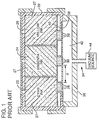
- FIG. 1 A prior art ink-jet pen and priming mechanism is depicted schematically in Fig. 1 and includes a multi-color ink-jet pen 20 divided into a cyan-ink supply compartment 22, a magenta-ink supply compartment 24, and a yellow-ink supply compartment 26.
- the cyan-ink compartment 22 supplies ink to an associated orifice set 28 formed in an orifice plate 40 that is mounted to the underside of the pen 20.
- the magenta-ink compartment 24 supplies ink to a second orifice set 30 in plate 40.
- the yellow-ink compartment 26 supplies ink to a third orifice set 32 in plate 40.
- the ink in each supply compartment is stored in an open-cell foam medium 27, which medium provides capillarity sufficient for preventing ink from leaking through orifices whenever a print head mechanism associated with each orifice (not shown) is inactive. Accordingly, the capillarity of the foam in each supply compartment 22, 24, 26 establishes a back pressure sufficient for preventing leakage of ink through the associated orifice sets 28, 30, 32.
- the prior priming apparatus 34 (Fig. 1) comprises a flexible connector member 36 that is movable against the outer surface 38 of the orifice plate 40.
- the connector member 36 is shaped to define a substantially sealed priming chamber 42.
- the priming chamber 42 is placed in fluid communication with a vacuum source 44.
- This invention is directed to a priming apparatus and process for multi-color ink-jet pens that provides effective priming of each orifice set in a multi-color pen without mixing colors, and that minimizes the amount of ink wasted during the priming process.
- Fig. 1 is a schematic cross-sectional diagram of a prior art system for priming a multi-color ink-jet pen.
- Fig. 2 is a schematic cross-sectional diagram of a preferred embodiment of an apparatus for priming a multi-color ink-jet pen in accordance with the present invention.
- Fig. 3 is a schematic diagram depicting the behavior of ink at a single orifice set during the time the priming process in underway.
- Fig. 4 is a schematic diagram depicting the behavior of ink at an orifice set at the completion of the priming process of the present invention.
- Fig. 5 is a graph depicting a preferred technique for regulating the ink supply compartment pressure change over time during a priming operation.
- Fig. 6 is a graph depicting another preferred technique for regulating the ink supply compartment and priming chamber pressure change over time during a preferred priming operation.
- Fig. 2 is a schematic diagram of a priming apparatus 50 formed in accordance with the present invention for priming a conventional multi-color ink-jet pen 52.
- the pen includes a housing 54 that defines therein a cyan-ink compartment 56, a magenta-ink compartment 58, and a yellow-ink compartment 60.
- Each ink compartment is filled with open-cell foam 61 that is saturated with ink as described more fully below.
- An orifice plate 62 is mounted to the underside of the pen housing 54. It is noteworthy that the schematic diagram of Fig. 2 is not to scale, the size of the pen housing 54 and the compartments defined therein being shown substantially smaller, relative to the orifice plate 62, than that of a conventional pen 52.
- the orifice plate 62 is fabricated by known means, such as electroforming.
- the plate 62 includes a set of orifices 64 formed therein and located to be in fluid communication with the cyan-ink supply compartment 56.
- a second orifice set 66 is formed in the orifice plate 62 and located to be in fluid communication with the magenta-ink compartment 58
- a third set of orifices 68 is formed in the orifice plate 62 to be in fluid communication with the yellow-ink compartment 60.
- the orifice sets 64, 66, 68 may comprise any of a number of individual orifices, although for illustrative purposes only five such orifices are depicted in each orifice set shown in Fig. 2.
- an orifice set may include as many as twenty-four orifices arranged in two parallel rows. The orifice sets are arranged to be very close together. For example, the minimum distance "d" (Fig. 2) between two orifice sets may be as little as 0.5 millimeters.
- Each orifice set 64, 66, 68 has associated with it a print head mechanism, such as a conventional thermal-bubble, thin-film resistor type (not shown), which is controllable for ejecting ink out of any one or more orifices of a set of orifices.
- a print head mechanism such as a conventional thermal-bubble, thin-film resistor type (not shown), which is controllable for ejecting ink out of any one or more orifices of a set of orifices.
- a supply channel 70 resides between the orifice set 64 and the cyan-ink compartment 56.
- a filter 72 against which the foam 61 in the cyan-ink compartment 56 is compressed extends between the compartment 56 and the supply channel 70.
- a supply channel 74 is defined between the magenta-ink compartment 58 and associated orifice set 66.
- a filter 78 extends across that channel 74.
- a third supply channel 76 across which a third filter 80 extends, is defined between the yellow-ink compartment 60 and associated orifice set 68.
- an ink-jet pen of the type described above will not operate unless there exists between the ink supply compartment and the orifice set a continuous path of ink. Accordingly, proper operation requires that each supply channel 70, 74, 76 be filled with ink and that no significant amount of air will be trapped between the ink supply and the orifice sets 64, 66, 68.
- the process of moving ink from the ink supply compartments to fill the supply channels is known as priming.
- the particulars of the preferred apparatus and process for priming the pen 52 are now discussed with reference to Figs. 2-5.
- the priming apparatus 50 generally includes a connector assembly 100, the primary components of which include a resilient seal member 102 that is mounted to a substantially rigid body 104.
- the body 104 is a block-shaped member having an upper surface 106 that extends in a plane generally parallel to the plane of the orifice plate outer surface 82 and that underlies all of the orifice sets 64, 66, 68 formed in the orifice plate 62.
- the resilient seal member 102 is fastened to the periphery of the body 104 to protrude upwardly therefrom above the upper surface 106. Consequently, as the orifice plate 62 and the seal member 102 are brought together into a priming position, as shown in Fig. 2, there is defined between the body 104 and orifice plate 62 a priming chamber 108 that is completely enclosed on the sides by the seal member 102.
- a suction tube 110 is mounted to the body 104 of the connector assembly 100 and arranged so that the upper end 112 of that tube 110 is disposed within the priming chamber 108 directly beneath the orifice set 64 and spaced a short distance or gap "G" (see Fig. 3) therefrom.
- the suction tube 110 is mounted to the body 104 so that the lower end 114 of the tube 110 is contiguous with an internal conduit 116 formed in the body 104. This arrangement provides fluid communication between the central opening 118 of the suction tube 110 and the vacuum conduit 116.
- the vacuum conduit 116 extends between the body 104 and a regulated vacuum source 120 for applying suction to the conduit 116 and, hence, to the connected suction tube 110.
- Additional suction tube and vacuum conduit arrangements substantially identical to the suction tube 110 and vacuum conduit 116 arrangement just described are included in the priming apparatus 50 so that immediately beneath the orifice set 66 of the magenta-ink supply compartment 58 there is an upper end 122 of another suction tube 124 spaced a short distance G (see Fig. 3) from the outer surface 82 of the orifice plate 62.
- the central opening 126 of this suction tube 124 is in fluid communication with a discrete (that is, separate from vacuum conduit 116) vacuum conduit 128, which conduit 128 is connected to the vacuum source 120.
- the vacuum source 120 applies suction to the suction tube 124.
- a third suction tube 132 is immediately beneath the orifice set 68 of the yellow-ink supply compartment 60.
- the central opening 134 of that suction tube 132 is in fluid communication with a discrete (that is, separate from conduits 116 and 128) vacuum conduit 136 that connects to the vacuum source 120 for applying suction to the internal opening 134 of the suction tube 132.
- the pen housing 54 is mounted to a fixture 140 during the time the pen 52 is primed.
- the fixture 140 secures the pen housing 54 as the connector assembly 100 is moved into the priming position so that the seal member 102 contacts the underside of the pen in the region of the orifice plate 62 to define the sealed priming chamber 108 mentioned above.
- the priming chamber 108 may be vented to ambient air (that is, when the apparatus 50 is in the priming position, Fig. 2) by a vent tube 142 that extends between ambient and the priming chamber 108.
- a valve 144 in the vent tube 142 is controlled by an operator for permitting or preventing fluid communication between the priming chamber 108 and ambient air. Accordingly, whenever the valve 144 is closed and the vacuum source 120 is activated, a partial vacuum will be established within the priming chamber 108 as fluid is drawn by the vacuum source 120 through the suction tubes 110, 124, 132. Opening the valve 144 substantially eliminates the partial vacuum in the priming chamber 108 as ambient air enters the priming chamber 108.
- the priming operation of the present invention is preferably, although not necessarily, undertaken in conjunction with the operation by which the pen 52 is filled with ink.
- the operation for filling the pen is briefly described next.
- the entire pen 52 is held by the fixture 140 substantially within a sealed container 150.
- the container 150 surrounds substantially all of the upper portion of the pen 52.
- the interior of the container 150 defines a fill chamber 152.
- the fill chamber 152 is in fluid communication with all of the ink supply compartments 56, 58, 60 as a result of the presence of fill apertures 154 formed in the upper part of the housing 54.
- the fill chamber 152 is connected to the vacuum source 120 (or any other regulated vacuum source) via a conduit 153 for the purpose of removing air in the fill chamber 152 and supply compartments 56, 58, 60 during the ink filling operation. In this regard, it is desirable to remove from the interior of the foam 61 any trapped air that would might hinder the dispersion of ink through the foam as the pen is filled.
- a hollow needle 156 is injected into the center of the foam in each compartment and the appropriate color of ink is pumped through the needle to fill the foam compartment with ink.
- the priming process commences.
- the operator closes vent valve 144 while the apparatus 50 is in the priming position (Fig. 2)
- the vacuum applied to the suction tubes 110, 124, 132 by the vacuum source 120 is, preferably, regulated so that the partial vacuum established within the priming chamber 108 will be that necessary for overcoming the capillarity of the foam 61, thereby to draw ink from the foam to fill each supply channel 70, 74, 76 and to force ink through each associated orifice set 64, 66, 68.
- the partial vacuum in the fill chamber 152 is substantially greater than (i.e., more negative relative to ambient) the partial vacuum established in the priming chamber 108. Accordingly, until the partial vacuum in the fill chamber 152 is reduced to a level below that in the priming chamber 108, ink will not flow toward the priming chamber 108. In a preferred embodiment of the invention, the partial vacuum in the fill chamber 152 is gradually reduced to a level less than that of the partial vacuum in the priming chamber 108, as described more fully below.
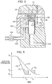
- Fig. 3 is a diagram of ink behavior at the orifice set during the priming process; that is, during the time valve 144 in the priming chamber vent is closed and the suction is applied via conduit 116 to the suction tube 110. It is understood that the following portion of the description applies to the behavior of the ink occurring at all suction tubes 124, 132.
- Ink 160 in the supply compartment 56 is drawn by the suction from the foam 61 through the filter 72 to fill the supply channel 70. From the supply channel 70, ink is drawn through the orifice set 64 and is eventually drawn into the central opening 118 of the tube from where it flows toward vacuum source 120 and is trapped and removed.
- the gap G between the upper end 112 and the surface 82 of the orifice plate 62 is small enough to ensure that the suction is communicated between the tube 112 and the orifice set 64. Moreover, the gap G between the tube 110 and orifice plate 62 provides a mechanism for removing any residual ink that may be present in the vicinity of the orifice set 64 at the conclusion of the priming process. In this regard, some of the ink 160 that is drawn from the supply channel 70 may form a liquid bridge 162 between the outer surface 82 of the orifice plate and the upper end 112 of the suction tube 110.
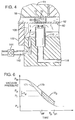
- the partial vacuum established in priming chamber 108 is rapidly reduced at the conclusion of the priming process by opening the valve 144 in the vent 142. Consequently, as shown in Fig. 4, air rushing through the vent tube 142, into the chamber 108 and into the suction tube 110 rapidly shears the ink bridges 162 so that substantially all of that ink 162 either enters the central opening 118 of the tube 110 or is drawn back into the individual orifices of the orifice set 64 to be held therein by the capillarity of the foam 61.
- the configuration and operation of the priming apparatus 50 substantially eliminates the presence of residual ink on the orifice plate at the end of the priming process.
- the partial vacuum in the fill chamber 152 is gradually reduced (that is, made less negative relative to ambient air) to a level less than that of the partial vacuum of the priming chamber 108.
- the mechanism for gradually reducing the partial vacuum in the fill chamber 152 may include, for example, a bleed valve 155 that can be manually or automatically operated to gradually permit ambient air to enter the conduit 153 via stub 157, thereby, gradually reducing the suction applied to the fill chamber 152.
- the effect of the gradual reduction of the partial vacuum in the fill chamber 152 is to minimize the amount of ink 160 that is removed from the pen during the time that the priming process is undertaken.
- the time period (hereafter called the priming time T p ) during which the partial vacuum established in the priming chamber 108 is greater than the capillarity of the foam 61 is selected for ensuring that all orifices of all orifice sets are free of any trapped air.
- This priming time T p may be, for example, 1.0 to 4.0 seconds.
- Fig. 5 graphically represents the effect of the gradual reduction of the fill chamber partial vacuum in reducing the amount of ink removed (hence, wasted) during priming.
- the ordinate of the graph represents vacuum pressure.
- the abscissa represents time, with the intervals T p representing priming time intervals T p .
- the value P f represents the pressure in the fill chamber 152 during the ink filling operation.
- the value P p represents the vacuum pressure in the priming chamber 108 as established by the regulated vacuum source 120.
- the value P c represents the back pressure established by the foam capillarity, which back pressure must be overcome by the priming pressure for drawing ink from the foam through the associated orifice sets.
- Line 170 of the graph in Fig. 5 depicts the relatively rapid reduction of the partial vacuum in fill chamber 152 that might occur when, for example, no bleed valve 155 were employed for gradual reduction of the chamber 152.
- Line 172 represents the relatively gradual reduction in the vacuum pressure in fill chamber 152 as occurs with the use of the bleed valve 155 of the present invention.
- the priming volume V1 associated with a rapid reduction of the partial vacuum in the fill chamber 152 (Line 170) is substantially greater than the priming volume V2 that occurs for the identical priming time T p when the fill chamber 152 is gradually reduced as indicated by line 172 of Fig. 5. Accordingly, it will be appreciated by one of ordinary skill in the art that the gradual reduction of the relative partial vacuums in the fill chamber 152 and priming chamber 108 (which gradual reduction is accomplished by the use of the bleed valve 155) permits priming of the pen while minimizing the amount of wasted ink.
- Another efficient technique for minimizing ink waste during priming involves varying both the fill chamber partial vacuum and the priming chamber partial vacuum during the priming time T p for maintaining throughout that time T p a pressure differential P d just large enough for drawing ink from the ink compartments.
- the vacuum source 120 which is connected to both the priming chamber 108 and the fill chamber 152 is controlled to simultaneously apply to both chambers 108, 152 a maximum partial vacuum P m during the filling process and before the priming process begins.
- the volume of air flowing from the priming chamber 108 and fill chamber 150 to the vacuum source 120 is regulated to establish the above-mentioned differential P d .
- line 171 represents the controlled reduction of the partial vacuum in the fill chamber 150
- line 173 represents the controlled reduction of the partial vacuum in the priming chamber 108.
- the vacuum pressure P p in the priming chamber 108 is greater by the differential amount P d than the vacuum pressure P f in the fill chamber 150.
- This differential P d is great enough to effect priming and is substantially maintained until the end T p1 of the priming time T p , at which time T p1 , the priming chamber partial vacuum is eliminated by venting that chamber to ambient as described above.
- priming process of the present invention was discussed as operable in conjunction with the pen filling operation. It will be appreciated, however, that the priming apparatus 50 of the present invention may be employed for priming the pen even after the pen is completely filled and capped.
Abstract
Description
- This invention relates to mechanisms for priming multi-color pens used in ink-jet printing.
- Pens used for ink-jet printing generally include an ink supply housed within the pen. The ink supply is in fluid communication with a set of orifices formed in an orifice plate that is mounted to the pen. A print head mechanism is controlled for forcing drops of ink through the orifice set as the pen is moved relative to a printing medium, such as paper. One such print head mechanism, known as a thermal bubble-type, includes a thin-film resistor associated with each orifice. The resistor is heated to cause sudden vaporization of a small amount of the ink near an orifice. The rapid expansion of the ink vapor forces an ink drop through the orifice.
- The ink supply for ink-jet pens is normally stored in a manner such that ink does not leak out of the orifices whenever the print head mechanism is inactive. In this regard, the ink may be stored in a compartment filled with open-cell foam so that the capillarity of the foam prevents the flow of ink out of orifices in the absence of the force generated by the activated print head mechanism for expelling drops.
- The mechanism for storing ink so that the ink does not leak from orifices when the print head mechanism is inactive may be different from one pen design to another. Irrespective of the particular storage mechanism used, however, there will be established in the ink storage or supply compartment a back pressure sufficient for resisting ink leakage whenever the print head mechanism is inactive. This back pressure holds ink at the orifice plate to define in each orifice an ink/air interface near the outer surface of the orifice plate. The print head mechanism overcomes the back pressure in ejecting ink from the orifices.
- An ink-jet pen, such as the thermal bubble-type just described, will not operate properly unless there exists between the ink supply compartment and the orifice set a continuous path of ink. Put another way, a filled pen must be primed by forcing ink from the supply compartment to the orifice set to eliminate any air that may be present between the ink supply and the orifice set.
- A conventional way to prime an ink-jet pen is to place the orifice set in fluid communication with a vacuum source for a time sufficient for drawing ink from the supply compartment and out through the orifice set.
- Multi-color ink-jet pens typically include three ink supply compartments, each compartment storing a specific color of ink. Each ink supply compartment is in fluid communication with an associated set of orifices so that one set of orifices ejects ink drops of a specific color. The three ink colors may be, for example, cyan, yellow, and magenta, and may be selectively applied to a printing medium to generate any of a multitude of colors through the process of subtractive color mixing.
- In order to ensure reliable color printing, it is important that an ink color associated with one orifice set does not mix with the colored ink of another orifice set prior to reaching the printing medium. Such undesirable mixing of one ink color with another ink color is likely to occur as a result of the priming process mentioned above. In this regard, some of the ink drawn from an ink supply compartment through an associated orifice set during priming may move out of the orifice set and flow along the outer surface of the orifice plate to a location near an orifice set of another color ink. When the priming force (suction) is removed, ink of one color may be drawn into the adjacent orifice set of another color by the back pressure established in the ink supply compartment.
- When two colors of ink mix in a single orifice set and are thereafter ejected by the print head, the resultant printed color is not that specified to the printer. Consequently, color print quality suffers until all of the mixed ink is ejected from the orifice set.
- In the past, the orifice sets of multi-color ink-jet pens were spaced far enough apart so that during the priming process ink of one color was unlikely to flow along the orifice plate outer surface for a distance sufficient to contact and mix with another color ink.
- A prior art ink-jet pen and priming mechanism is depicted schematically in Fig. 1 and includes a multi-color ink-
jet pen 20 divided into a cyan-ink supply compartment 22, a magenta-ink supply compartment 24, and a yellow-ink supply compartment 26. - The cyan-
ink compartment 22 supplies ink to an associated orifice set 28 formed in anorifice plate 40 that is mounted to the underside of thepen 20. The magenta-ink compartment 24 supplies ink to a second orifice set 30 inplate 40. The yellow-ink compartment 26 supplies ink to a third orifice set 32 inplate 40. The ink in each supply compartment is stored in an open-cell foam medium 27, which medium provides capillarity sufficient for preventing ink from leaking through orifices whenever a print head mechanism associated with each orifice (not shown) is inactive. Accordingly, the capillarity of the foam in eachsupply compartment orifice sets - The prior priming apparatus 34 (Fig. 1) comprises a
flexible connector member 36 that is movable against theouter surface 38 of theorifice plate 40. Theconnector member 36 is shaped to define a substantially sealedpriming chamber 42. Thepriming chamber 42 is placed in fluid communication with avacuum source 44. Once eachink compartment connector member 36 is moved against theorifice plate 40 and a partial vacuum is established within thepriming chamber 42 by thevacuum source 44. Ink is, therefore, drawn from each ink supply compartment through an associated orifice set 28, 30, 32. Ink drawn out of an orifice set flows toward thevacuum source 42 to be trapped and disposed of. After a time sufficient for drawing the ink in each compartment through each associated orifice set, the vacuum is removed and the back pressure within each supply compartment thereafter prevents ink from leaking from the orifice sets. - As mentioned above, prior ink-jet pen designs are such that the minimum distance "d" (Fig. 1) between any two orifice sets is great enough so that any ink residing on the
outer surface 38 of theorifice plate 40 after the priming process is unlikely to flow the distance "d" to an adjacent orifice set and cause the undesirable mixing mentioned above. As an added measure for preventing printing problems where mixing may occur, the pen is operated for a short time to expel any mixed ink before the pen is packaged for sale. - Current designs of orifice plates for multi-color ink-jet pens have substantially reduced the minimum distance between orifice sets. Accordingly, the likelihood of color mixing as a result of the priming process is increased since residual ink on the orifice plate outer surface need travel only a short distance before mixing with a color of an adjacent orifice set. Expelling mixed ink prior to pen packaging is unacceptable because of the attendant waste of ink. Moreover, mixed ink tends to rapidly disperse into the ink supply, thereby making it difficult to efficiently expel all of the mixed ink prior to packaging.
- This invention is directed to a priming apparatus and process for multi-color ink-jet pens that provides effective priming of each orifice set in a multi-color pen without mixing colors, and that minimizes the amount of ink wasted during the priming process.
- Fig. 1 is a schematic cross-sectional diagram of a prior art system for priming a multi-color ink-jet pen.
- Fig. 2 is a schematic cross-sectional diagram of a preferred embodiment of an apparatus for priming a multi-color ink-jet pen in accordance with the present invention.
- Fig. 3 is a schematic diagram depicting the behavior of ink at a single orifice set during the time the priming process in underway.
- Fig. 4 is a schematic diagram depicting the behavior of ink at an orifice set at the completion of the priming process of the present invention.
- Fig. 5 is a graph depicting a preferred technique for regulating the ink supply compartment pressure change over time during a priming operation.
- Fig. 6 is a graph depicting another preferred technique for regulating the ink supply compartment and priming chamber pressure change over time during a preferred priming operation.
- Fig. 2 is a schematic diagram of a
priming apparatus 50 formed in accordance with the present invention for priming a conventional multi-color ink-jet pen 52. The pen includes ahousing 54 that defines therein a cyan-ink compartment 56, a magenta-ink compartment 58, and a yellow-ink compartment 60. Each ink compartment is filled with open-cell foam 61 that is saturated with ink as described more fully below. Anorifice plate 62 is mounted to the underside of thepen housing 54. It is noteworthy that the schematic diagram of Fig. 2 is not to scale, the size of thepen housing 54 and the compartments defined therein being shown substantially smaller, relative to theorifice plate 62, than that of aconventional pen 52. - The
orifice plate 62 is fabricated by known means, such as electroforming. Theplate 62 includes a set oforifices 64 formed therein and located to be in fluid communication with the cyan-ink supply compartment 56. Similarly, asecond orifice set 66 is formed in theorifice plate 62 and located to be in fluid communication with the magenta-ink compartment 58, and a third set oforifices 68 is formed in theorifice plate 62 to be in fluid communication with the yellow-ink compartment 60. - The orifice sets 64, 66, 68 may comprise any of a number of individual orifices, although for illustrative purposes only five such orifices are depicted in each orifice set shown in Fig. 2. In one preferred embodiment, an orifice set may include as many as twenty-four orifices arranged in two parallel rows. The orifice sets are arranged to be very close together. For example, the minimum distance "d" (Fig. 2) between two orifice sets may be as little as 0.5 millimeters.
- Each orifice set 64, 66, 68 has associated with it a print head mechanism, such as a conventional thermal-bubble, thin-film resistor type (not shown), which is controllable for ejecting ink out of any one or more orifices of a set of orifices.
- A
supply channel 70 resides between the orifice set 64 and the cyan-ink compartment 56. Afilter 72, against which thefoam 61 in the cyan-ink compartment 56 is compressed extends between thecompartment 56 and thesupply channel 70. Similarly, asupply channel 74 is defined between the magenta-ink compartment 58 and associated orifice set 66. Afilter 78 extends across thatchannel 74. Athird supply channel 76, across which athird filter 80 extends, is defined between the yellow-ink compartment 60 and associated orifice set 68. - As noted earlier, an ink-jet pen of the type described above will not operate unless there exists between the ink supply compartment and the orifice set a continuous path of ink. Accordingly, proper operation requires that each
supply channel pen 52 are now discussed with reference to Figs. 2-5. - The
priming apparatus 50 generally includes aconnector assembly 100, the primary components of which include aresilient seal member 102 that is mounted to a substantiallyrigid body 104. Thebody 104 is a block-shaped member having anupper surface 106 that extends in a plane generally parallel to the plane of the orifice plateouter surface 82 and that underlies all of the orifice sets 64, 66, 68 formed in theorifice plate 62. - The
resilient seal member 102 is fastened to the periphery of thebody 104 to protrude upwardly therefrom above theupper surface 106. Consequently, as theorifice plate 62 and theseal member 102 are brought together into a priming position, as shown in Fig. 2, there is defined between thebody 104 and orifice plate 62 apriming chamber 108 that is completely enclosed on the sides by theseal member 102. - A
suction tube 110 is mounted to thebody 104 of theconnector assembly 100 and arranged so that theupper end 112 of thattube 110 is disposed within thepriming chamber 108 directly beneath the orifice set 64 and spaced a short distance or gap "G" (see Fig. 3) therefrom. Thesuction tube 110 is mounted to thebody 104 so that thelower end 114 of thetube 110 is contiguous with aninternal conduit 116 formed in thebody 104. This arrangement provides fluid communication between thecentral opening 118 of thesuction tube 110 and thevacuum conduit 116. Thevacuum conduit 116 extends between thebody 104 and aregulated vacuum source 120 for applying suction to theconduit 116 and, hence, to theconnected suction tube 110. - Additional suction tube and vacuum conduit arrangements substantially identical to the
suction tube 110 andvacuum conduit 116 arrangement just described are included in thepriming apparatus 50 so that immediately beneath the orifice set 66 of the magenta-ink supply compartment 58 there is an upper end 122 of anothersuction tube 124 spaced a short distance G (see Fig. 3) from theouter surface 82 of theorifice plate 62. Thecentral opening 126 of thissuction tube 124 is in fluid communication with a discrete (that is, separate from vacuum conduit 116)vacuum conduit 128, whichconduit 128 is connected to thevacuum source 120. Thevacuum source 120 applies suction to thesuction tube 124. - The
upper end 130 of athird suction tube 132 is immediately beneath the orifice set 68 of the yellow-ink supply compartment 60. Thecentral opening 134 of thatsuction tube 132 is in fluid communication with a discrete (that is, separate fromconduits 116 and 128)vacuum conduit 136 that connects to thevacuum source 120 for applying suction to theinternal opening 134 of thesuction tube 132. - In the preferred embodiment, the
pen housing 54 is mounted to afixture 140 during the time thepen 52 is primed. Thefixture 140 secures thepen housing 54 as theconnector assembly 100 is moved into the priming position so that theseal member 102 contacts the underside of the pen in the region of theorifice plate 62 to define the sealedpriming chamber 108 mentioned above. - The
priming chamber 108 may be vented to ambient air (that is, when theapparatus 50 is in the priming position, Fig. 2) by avent tube 142 that extends between ambient and thepriming chamber 108. Avalve 144 in thevent tube 142 is controlled by an operator for permitting or preventing fluid communication between the primingchamber 108 and ambient air. Accordingly, whenever thevalve 144 is closed and thevacuum source 120 is activated, a partial vacuum will be established within thepriming chamber 108 as fluid is drawn by thevacuum source 120 through thesuction tubes valve 144 substantially eliminates the partial vacuum in thepriming chamber 108 as ambient air enters thepriming chamber 108. - The priming operation of the present invention is preferably, although not necessarily, undertaken in conjunction with the operation by which the
pen 52 is filled with ink. The operation for filling the pen is briefly described next. - During the fill operation, the
entire pen 52, except for a top cap not shown in Fig. 2, is held by thefixture 140 substantially within a sealedcontainer 150. Thecontainer 150 surrounds substantially all of the upper portion of thepen 52. The interior of thecontainer 150 defines afill chamber 152. Thefill chamber 152 is in fluid communication with all of the ink supply compartments 56, 58, 60 as a result of the presence offill apertures 154 formed in the upper part of thehousing 54. - The
fill chamber 152 is connected to the vacuum source 120 (or any other regulated vacuum source) via aconduit 153 for the purpose of removing air in thefill chamber 152 andsupply compartments foam 61 any trapped air that would might hinder the dispersion of ink through the foam as the pen is filled. - Once a partial vacuum is established in the fill chamber 152 (hence, in ink compartments 56, 58, 60), a
hollow needle 156 is injected into the center of the foam in each compartment and the appropriate color of ink is pumped through the needle to fill the foam compartment with ink. - Once the ink compartments 56, 58, 60 are filled with ink, the priming process commences. To this end, the operator closes
vent valve 144 while theapparatus 50 is in the priming position (Fig. 2) The vacuum applied to thesuction tubes vacuum source 120 is, preferably, regulated so that the partial vacuum established within thepriming chamber 108 will be that necessary for overcoming the capillarity of thefoam 61, thereby to draw ink from the foam to fill eachsupply channel - During the time the pen is filled with ink, the partial vacuum in the
fill chamber 152 is substantially greater than (i.e., more negative relative to ambient) the partial vacuum established in thepriming chamber 108. Accordingly, until the partial vacuum in thefill chamber 152 is reduced to a level below that in thepriming chamber 108, ink will not flow toward thepriming chamber 108. In a preferred embodiment of the invention, the partial vacuum in thefill chamber 152 is gradually reduced to a level less than that of the partial vacuum in thepriming chamber 108, as described more fully below. - Fig. 3 is a diagram of ink behavior at the orifice set during the priming process; that is, during the
time valve 144 in the priming chamber vent is closed and the suction is applied viaconduit 116 to thesuction tube 110. It is understood that the following portion of the description applies to the behavior of the ink occurring at allsuction tubes - Ink 160 in the
supply compartment 56 is drawn by the suction from thefoam 61 through thefilter 72 to fill thesupply channel 70. From thesupply channel 70, ink is drawn through the orifice set 64 and is eventually drawn into thecentral opening 118 of the tube from where it flows towardvacuum source 120 and is trapped and removed. - The gap G between the
upper end 112 and thesurface 82 of theorifice plate 62 is small enough to ensure that the suction is communicated between thetube 112 and the orifice set 64. Moreover, the gap G between thetube 110 andorifice plate 62 provides a mechanism for removing any residual ink that may be present in the vicinity of the orifice set 64 at the conclusion of the priming process. In this regard, some of the ink 160 that is drawn from thesupply channel 70 may form aliquid bridge 162 between theouter surface 82 of the orifice plate and theupper end 112 of thesuction tube 110. In order to ensure that substantially none of this bridgingink 162 remains on theouter surface 82 of the orifice plate 62 (hence, being capable of flowing to and mixing with ink in an adjacent orifice set), the partial vacuum established in primingchamber 108 is rapidly reduced at the conclusion of the priming process by opening thevalve 144 in thevent 142. Consequently, as shown in Fig. 4, air rushing through thevent tube 142, into thechamber 108 and into thesuction tube 110 rapidly shears the ink bridges 162 so that substantially all of thatink 162 either enters thecentral opening 118 of thetube 110 or is drawn back into the individual orifices of the orifice set 64 to be held therein by the capillarity of thefoam 61. In short, the configuration and operation of thepriming apparatus 50 substantially eliminates the presence of residual ink on the orifice plate at the end of the priming process. - As mentioned earlier, the partial vacuum in the
fill chamber 152 is gradually reduced (that is, made less negative relative to ambient air) to a level less than that of the partial vacuum of thepriming chamber 108. The mechanism for gradually reducing the partial vacuum in thefill chamber 152 may include, for example, ableed valve 155 that can be manually or automatically operated to gradually permit ambient air to enter theconduit 153 viastub 157, thereby, gradually reducing the suction applied to thefill chamber 152. - The effect of the gradual reduction of the partial vacuum in the
fill chamber 152 is to minimize the amount of ink 160 that is removed from the pen during the time that the priming process is undertaken. In this regard, the time period (hereafter called the priming time Tp) during which the partial vacuum established in thepriming chamber 108 is greater than the capillarity of thefoam 61 is selected for ensuring that all orifices of all orifice sets are free of any trapped air. This priming time Tp may be, for example, 1.0 to 4.0 seconds. - Fig. 5 graphically represents the effect of the gradual reduction of the fill chamber partial vacuum in reducing the amount of ink removed (hence, wasted) during priming. The ordinate of the graph represents vacuum pressure. The abscissa represents time, with the intervals Tp representing priming time intervals Tp. The value Pf represents the pressure in the
fill chamber 152 during the ink filling operation. The value Pp represents the vacuum pressure in thepriming chamber 108 as established by theregulated vacuum source 120. The value Pc represents the back pressure established by the foam capillarity, which back pressure must be overcome by the priming pressure for drawing ink from the foam through the associated orifice sets. -
Line 170 of the graph in Fig. 5 depicts the relatively rapid reduction of the partial vacuum infill chamber 152 that might occur when, for example, nobleed valve 155 were employed for gradual reduction of thechamber 152.Line 172 represents the relatively gradual reduction in the vacuum pressure infill chamber 152 as occurs with the use of thebleed valve 155 of the present invention. Once the vacuum pressure in thefill chamber 152 is reduced to that below the pressure Pp in thepriming chamber 108, a volume of ink, hereafter referred to as a priming volume, will be removed from the fill compartment over a given priming time Tp. - Upon review of the graph of Fig. 5 it can be appreciated that the priming volume V₁ associated with a rapid reduction of the partial vacuum in the fill chamber 152 (Line 170) is substantially greater than the priming volume V₂ that occurs for the identical priming time Tp when the
fill chamber 152 is gradually reduced as indicated byline 172 of Fig. 5. Accordingly, it will be appreciated by one of ordinary skill in the art that the gradual reduction of the relative partial vacuums in thefill chamber 152 and priming chamber 108 (which gradual reduction is accomplished by the use of the bleed valve 155) permits priming of the pen while minimizing the amount of wasted ink. - Another efficient technique for minimizing ink waste during priming involves varying both the fill chamber partial vacuum and the priming chamber partial vacuum during the priming time Tp for maintaining throughout that time Tp a pressure differential Pd just large enough for drawing ink from the ink compartments.
- With reference to Fig. 6, the
vacuum source 120, which is connected to both thepriming chamber 108 and thefill chamber 152 is controlled to simultaneously apply to bothchambers 108, 152 a maximum partial vacuum Pm during the filling process and before the priming process begins. Once the priming process begins, the volume of air flowing from thepriming chamber 108 and fillchamber 150 to thevacuum source 120 is regulated to establish the above-mentioned differential Pd. In this regard,line 171 represents the controlled reduction of the partial vacuum in thefill chamber 150 andline 173 represents the controlled reduction of the partial vacuum in thepriming chamber 108. At the beginning TpØ of the priming time Tp, the vacuum pressure Pp in thepriming chamber 108 is greater by the differential amount Pd than the vacuum pressure Pf in thefill chamber 150. This differential Pd is great enough to effect priming and is substantially maintained until the end Tp1 of the priming time Tp, at which time Tp1, the priming chamber partial vacuum is eliminated by venting that chamber to ambient as described above. - It can be appreciated that the use of the just described technique minimizes the volume of ink (that volume represented by area V₃ in Fig. 6) that is wasted during a given priming time Tp.
- It is noteworthy that the priming process of the present invention was discussed as operable in conjunction with the pen filling operation. It will be appreciated, however, that the
priming apparatus 50 of the present invention may be employed for priming the pen even after the pen is completely filled and capped. - While having described and illustrated the principles of the invention with reference to preferred embodiments and alternatives, it should be apparent that the invention can be further modified in arrangement and detail without departing from such principles. Accordingly, it is understood that the present invention includes all such modification that may come within the scope and spirit of the following claims and equivalents thereof.
Claims (17)
- An apparatus for priming a pen (52) that includes an orifice plate (62) having a first set of orifices in fluid communication with a supply of first-color ink and a second set of orifices in fluid communication with a supply of second-color ink, the apparatus comprising:
a connector member (100) movable to a priming position near the orifice plate;
first and second tubular members (110, 124) mounted to the connector member and arranged so that the first tubular member terminates near the first set (64) of orifices and the second tubular member terminates near the second set (66) of orifices; and
a vacuum source (120) connected to the first and second tubular members for applying suction in both tubular members so that the suction in the first tubular member urges the first-color ink through the first set of orifices and the suction in the second tubular member urges the second-color ink through the second set of orifices. - The apparatus of claim 1 wherein the connector member includes a body (104) and a seal member (102) attached to the body, the seal member contacting the orifice plate (62) when the connector member is in the priming position, the seal member, plate, and body defining a first chamber (108) in which the first and second tubular members terminate; and
vent means (142, 144) operable for sealing the first chamber from ambient air thereby reducing the pressure in the first chamber as suction is applied to the first and second tubular members. - The apparatus of claim 2 wherein the vent means (142) is operable for placing the first chamber (108) in fluid communication with ambient air while the connector member (100) is in the priming position.
- The apparatus of claim 3 wherein the vent means includes a valve (144) and vent tube (142) mounted to the connector member, the valve being openable for connecting the first chamber with ambient air and closable for sealing the first chamber from ambient air.
- The apparatus of claim 2 further comprising:
a container (150) to which the pen (52) is mounted, the container being configured for defining a second chamber (152) with which the stored first-color ink and second-color ink are in fluid communication, the vacuum source (120) being connected to the second chamber for producing a partial vacuum in the second chamber; and
control means for gradually reducing the partial vacuum in the second chamber as the suction is applied by the source means to the first chamber. - The apparatus of claim 1 wherein the vacuum source (120) is connected to the first and second tubular members by discrete conduits so that blockage of one such conduit does not eliminate suction applied to the tubular member that is connected to another discrete conduit.
- A priming apparatus for a pen that (52) includes an orifice plate (62) having a first set of orifices (64) in fluid communication with a supply of first-color ink and a second set of orifices (66) in fluid communication with a supply of second-color ink, the apparatus comprising:
a connector member (100) positionable against the orifice plate to define a first chamber (108) with which the first and second sets of orifices are in fluid communication;
a container (150) for securing the pen, the container being configured for defining a second chamber (152) with which the stored first-color ink and second-color ink are in fluid communication;
vacuum means (120) for generating partial vacuum in the first and second chamber; and
control means for gradually reducing the partial vacuum in the second chamber while the partial vacuum remains in the first chamber for urging first-color ink through the first set of orifices and for urging second-color ink through the second set of orifices. - The apparatus of claim 7 further comprising first and second tubular members mounted to the connector member and arranged so that the first tubular member (110) terminates near the first set of orifices (64) and the second tubular member (124) terminates near the second set of orifices (66); and
a vacuum source connected to the first and second tubular members for applying suction in both tubular members so that the suction in the first and second tubular members generates the partial vacuum in the first chamber (108). - The apparatus of claim 8 further comprising vent means (142,144) for rapidly venting the first chamber to ambient while the connector member (100) is positioned against the orifice plate.
- The apparatus of claim 8 wherein the vacuum source is connected by a conduit (153) to the second chamber, the vacuum source generating the partial vacuum in the second chamber.
- The apparatus of claim 10 wherein the control means includes a valve (155) attached to the conduit for reducing the magnitude of the partial vacuum applied to the second chamber.
- The apparatus of claim 8 wherein the first and second tubular members are connected to the vacuum source by discrete conduits (116, 128) so that blockage of one conduit does not eliminate suction applied to the tubular member that is connected to another discrete conduit.
- A method of priming ink through first and second sets of orifices of an orifice plate (62) of a pen (52) that has a first-color ink stored in fluid communication with the first set of orifices (64) and a second-color ink stored in fluid communication with the second set of orifices (66), the method comprising the steps of:
positioning an end of a first tubular member (110) near the first set of orifices;
positioning an end of a second tubular member (124) near the second set of orifices; and
applying to the first and second tubular members suction for urging the first-color ink through the first set of orifices toward the end of the first tubular member and for urging the second-color ink through the second set of orifices toward the end of the second tubular member. - The method of claim 13, further comprising the steps of defining a first chamber (108) adjacent to the orifice plate in which chamber resides the ends of the first and second tubular members; and
sealing the first chamber from ambient so that suction applied to the tubular members decreases the pressure within the chamber. - A method of priming first and second sets of orifices of an orifice plate (62) that has a first-color ink stored in fluid communication with the first set of orifices (64) and a second-color ink stored in fluid communication with the second set of orifices (66), the method comprising the steps of:
defining a first chamber (108) with which the first and second sets of orifices are in fluid communication;
defining a second chamber (152) with which the stored first-color ink and second-color ink are in fluid communication;
applying a partial vacuum to the first and second chambers; and
gradually reducing the magnitude of the partial vacuum in the second chamber while maintaining the partial vacuum in the first chamber so that the partial vacuum in the first chamber begins to urge the first-color ink through the first set of orifices and the second-color ink through the second set of orifices. - The method of claim 15 further including the step of venting to ambient the first chamber after the first-color ink and the second-color ink moves through the associated first and second set of orifices.
- The method of claim 15 including the step of gradually reducing the magnitude of the partial vacuum in the first chamber a rate relative to that of the second chamber to maintain over a priming time a predetermined differential between the partial vacuum in the first and second chambers.
Applications Claiming Priority (2)
| Application Number | Priority Date | Filing Date | Title |
|---|---|---|---|
| US686740 | 1991-04-17 | ||
| US07/686,740 US5185614A (en) | 1991-04-17 | 1991-04-17 | Priming apparatus and process for multi-color ink-jet pens |
Publications (3)
| Publication Number | Publication Date |
|---|---|
| EP0509687A2 true EP0509687A2 (en) | 1992-10-21 |
| EP0509687A3 EP0509687A3 (en) | 1993-06-09 |
| EP0509687B1 EP0509687B1 (en) | 1996-09-11 |
Family
ID=24757545
Family Applications (1)
| Application Number | Title | Priority Date | Filing Date |
|---|---|---|---|
| EP92302952A Expired - Lifetime EP0509687B1 (en) | 1991-04-17 | 1992-04-03 | Priming apparatus and process for multi-color ink-jet pens |
Country Status (6)
| Country | Link |
|---|---|
| US (1) | US5185614A (en) |
| EP (1) | EP0509687B1 (en) |
| JP (1) | JP3203045B2 (en) |
| CA (1) | CA2060618A1 (en) |
| DE (1) | DE69213535T2 (en) |
| HK (1) | HK64597A (en) |
Cited By (9)
| Publication number | Priority date | Publication date | Assignee | Title |
|---|---|---|---|---|
| EP0603910A1 (en) * | 1992-12-25 | 1994-06-29 | Canon Kabushiki Kaisha | Ink loading device, recording apparatus having same and ink loading method |
| EP0631872A2 (en) * | 1993-06-30 | 1995-01-04 | Canon Kabushiki Kaisha | Ink jet jead, ink jet apparatus and method of recoverably activating in the apparatus |
| EP0631871A2 (en) * | 1993-05-25 | 1995-01-04 | Canon Kabushiki Kaisha | Recovery device for maintaining recording quality in an ink jet apparatus |
| FR2713551A1 (en) * | 1993-12-10 | 1995-06-16 | Seiko Epson Corp | Ink jet recording apparatus. |
| FR2722139A1 (en) * | 1993-12-10 | 1996-01-12 | Seiko Epson Corp | Ink-jet recording appts. e.g. on=demand colour printer |
| EP0711668A2 (en) * | 1994-11-12 | 1996-05-15 | PMS GmbH, Produktion + Recycling von Büromaschinenzubehör | Ink refilling apparatus for ink jet cartridge |
| EP1088664A1 (en) * | 1999-09-28 | 2001-04-04 | Eastman Kodak Company | A self-cleaning ink jet printer system with a reversible fluid flow and a method of assembling the printer system |
| EP1088665A1 (en) * | 1999-09-28 | 2001-04-04 | Eastman Kodak Company | A self-cleaning ink jet printer system with a reversible fluid flow and a rotating roller and method of assembling the printer system |
| WO2008055101A2 (en) | 2006-10-30 | 2008-05-08 | Hewlett-Packard Development Company, L.P. | Introducing ink into an ink cartridge |
Families Citing this family (33)
| Publication number | Priority date | Publication date | Assignee | Title |
|---|---|---|---|---|
| US5485187A (en) * | 1991-10-02 | 1996-01-16 | Canon Kabushiki Kaisha | Ink-jet recording apparatus having improved recovery device |
| JP3155871B2 (en) * | 1992-10-30 | 2001-04-16 | キヤノン株式会社 | Ink jet recording device |
| US5489925A (en) * | 1993-05-04 | 1996-02-06 | Markem Corporation | Ink jet printing system |
| US5742308A (en) * | 1994-03-30 | 1998-04-21 | Hewlett-Packard Company | Ink jet printer cartridge refilling method and apparatus |
| US5691755A (en) * | 1994-04-18 | 1997-11-25 | Hewlett-Packard Company | Collapsible ink cartridge |
| US6095633A (en) * | 1994-10-06 | 2000-08-01 | Lexmark International, Inc. | Process for priming a multi-chamber ink jet print head |
| US5714991A (en) * | 1995-03-03 | 1998-02-03 | Hewlett-Packard Company | Rotary priming system for inkjet printheads |
| US5936650A (en) * | 1995-05-24 | 1999-08-10 | Hewlett Packard Company | Ink delivery system for ink-jet pens |
| US5812155A (en) * | 1995-10-27 | 1998-09-22 | Hewlett-Packard Company | Apparatus for removing air from an ink-jet print cartridge |
| US6257714B1 (en) | 1995-10-27 | 2001-07-10 | Hewlett-Packard Company | Method and apparatus for removing air from an inkjet print cartridge |
| US5760805A (en) * | 1996-06-24 | 1998-06-02 | Xerox Corporation | Ink supply container with improved foam retention properties |
| US6189995B1 (en) * | 1997-03-04 | 2001-02-20 | Hewlett-Packard Company | Manually replaceable printhead servicing module for each different inkjet printhead |
| US6042226A (en) * | 1997-03-10 | 2000-03-28 | Hewlett-Packard Company | Apparatus and method of priming ink supply tubes in an ink jet printer |
| US6158837A (en) * | 1997-09-19 | 2000-12-12 | Xerox Corporation | Printer having print mode for non-qualified marking material |
| US6106088A (en) * | 1997-10-01 | 2000-08-22 | Xerox Corporation | Printhead assembly with integral lifetime monitoring system |
| US5971531A (en) * | 1997-10-08 | 1999-10-26 | Xerox Corporation | Ink jet cartridge having replaceable ink supply tanks with an internal filter |
| US6039443A (en) * | 1997-12-12 | 2000-03-21 | Hewlett-Packard Company | Apparatus and method of priming ink supply tubes in an ink jet printer |
| US6139136A (en) * | 1997-12-17 | 2000-10-31 | Pitney Bowes Inc. | Ink supply system including a multiple level ink reservoir for ink jet printing |
| US6012807A (en) * | 1998-03-06 | 2000-01-11 | Hewlett-Packard Company | Ink containment unit for use in an ink delivery system |
| JPH11320908A (en) | 1998-04-06 | 1999-11-24 | Xerox Corp | Ink supply container |
| US5905518A (en) * | 1998-04-29 | 1999-05-18 | Hewlett-Packard Company | One shot air purge for replaceable ink supply |
| US6241349B1 (en) | 1999-01-28 | 2001-06-05 | Hewlett-Packard Company | High-durability ink containment unit for use in an ink delivery system |
| US6312083B1 (en) | 1999-12-20 | 2001-11-06 | Xerox Corporation | Printhead assembly with ink monitoring system |
| US6196671B1 (en) | 1999-12-20 | 2001-03-06 | Xerox Corporation | Ink-jet cartridge for an ink jet printer having air ingestion control |
| US6257715B1 (en) | 2000-03-07 | 2001-07-10 | Hewlett-Packard Company | Ink jet printer with ink conduit gas exhaust facility and method |
| US6402293B1 (en) * | 2000-06-16 | 2002-06-11 | Xerox Corp. | Vacuum accumulator and ink manifold |
| US6991311B2 (en) * | 2003-12-12 | 2006-01-31 | Industrial Technology Research Institute | Apparatus and method for introducing micro-volume liquid |
| US7448734B2 (en) | 2004-01-21 | 2008-11-11 | Silverbrook Research Pty Ltd | Inkjet printer cartridge with pagewidth printhead |
| US20050157112A1 (en) | 2004-01-21 | 2005-07-21 | Silverbrook Research Pty Ltd | Inkjet printer cradle with shaped recess for receiving a printer cartridge |
| JP4760401B2 (en) * | 2006-01-30 | 2011-08-31 | セイコーエプソン株式会社 | Cap and liquid ejecting apparatus |
| US8172348B2 (en) | 2008-03-24 | 2012-05-08 | Hewlett-Packard Development Company, L.P. | Print head cap vent |
| US11083982B2 (en) * | 2016-04-11 | 2021-08-10 | Hewlett-Packard Development Company, L.P. | Coalescing frothy fluids |
| CN114714769A (en) * | 2022-03-30 | 2022-07-08 | 华中科技大学无锡研究院 | Anti-corrosion ink box, ink-jet printing device and preparation method of QLED light-emitting device |
Citations (4)
| Publication number | Priority date | Publication date | Assignee | Title |
|---|---|---|---|---|
| JPS5863453A (en) * | 1981-10-13 | 1983-04-15 | Seiko Epson Corp | Multicolor ink jet recorder |
| EP0143213A1 (en) * | 1983-09-30 | 1985-06-05 | Siemens Aktiengesellschaft | Automatic device for ventilating under pressure the ink supply reservoir of a printer |
| US4771295A (en) * | 1986-07-01 | 1988-09-13 | Hewlett-Packard Company | Thermal ink jet pen body construction having improved ink storage and feed capability |
| US4833491A (en) * | 1988-06-15 | 1989-05-23 | Xerox Corporation | Thermal ink jet printer adapted to operate in monochrome, highlight or process color modes |
Family Cites Families (5)
| Publication number | Priority date | Publication date | Assignee | Title |
|---|---|---|---|---|
| JPS5932313B2 (en) * | 1976-06-07 | 1984-08-08 | コニカ株式会社 | Method for cleaning ink passages in inkjet recording devices |
| CA1195178A (en) * | 1981-10-08 | 1985-10-15 | Koji Terasawa | Capping device for a multi-ink jet head |
| US4510510A (en) * | 1982-04-13 | 1985-04-09 | Canon Kabushiki Kaisha | Inkjet printer |
| US4727378A (en) * | 1986-07-11 | 1988-02-23 | Tektronix, Inc. | Method and apparatus for purging an ink jet head |
| JP2817924B2 (en) * | 1987-11-17 | 1998-10-30 | キヤノン株式会社 | Ink jet recording device |
-
1991
- 1991-04-17 US US07/686,740 patent/US5185614A/en not_active Expired - Lifetime
-
1992
- 1992-02-04 CA CA002060618A patent/CA2060618A1/en not_active Abandoned
- 1992-04-03 DE DE69213535T patent/DE69213535T2/en not_active Expired - Fee Related
- 1992-04-03 EP EP92302952A patent/EP0509687B1/en not_active Expired - Lifetime
- 1992-04-17 JP JP12419992A patent/JP3203045B2/en not_active Expired - Fee Related
-
1997
- 1997-05-15 HK HK64597A patent/HK64597A/en not_active IP Right Cessation
Patent Citations (5)
| Publication number | Priority date | Publication date | Assignee | Title |
|---|---|---|---|---|
| JPS5863453A (en) * | 1981-10-13 | 1983-04-15 | Seiko Epson Corp | Multicolor ink jet recorder |
| EP0143213A1 (en) * | 1983-09-30 | 1985-06-05 | Siemens Aktiengesellschaft | Automatic device for ventilating under pressure the ink supply reservoir of a printer |
| US4771295A (en) * | 1986-07-01 | 1988-09-13 | Hewlett-Packard Company | Thermal ink jet pen body construction having improved ink storage and feed capability |
| US4771295B1 (en) * | 1986-07-01 | 1995-08-01 | Hewlett Packard Co | Thermal ink jet pen body construction having improved ink storage and feed capability |
| US4833491A (en) * | 1988-06-15 | 1989-05-23 | Xerox Corporation | Thermal ink jet printer adapted to operate in monochrome, highlight or process color modes |
Non-Patent Citations (1)
| Title |
|---|
| PATENT ABSTRACTS OF JAPAN vol. 7, no. 157 (M-227)(1302) 9 July 1983 & JP-A-58 63 453 ( EPUSON ) 15 April 1983 * |
Cited By (19)
| Publication number | Priority date | Publication date | Assignee | Title |
|---|---|---|---|---|
| EP0603910A1 (en) * | 1992-12-25 | 1994-06-29 | Canon Kabushiki Kaisha | Ink loading device, recording apparatus having same and ink loading method |
| US5504510A (en) * | 1992-12-25 | 1996-04-02 | Canon Kabushiki Kaisha | Ink loading device, recording apparatus having same and ink loading method |
| US5835109A (en) * | 1993-05-25 | 1998-11-10 | Canon Kabushiki Kaisha | Ink jet apparatus with collectively capped multicolor ink discharge openings |
| EP0631871A2 (en) * | 1993-05-25 | 1995-01-04 | Canon Kabushiki Kaisha | Recovery device for maintaining recording quality in an ink jet apparatus |
| EP0631871A3 (en) * | 1993-05-25 | 1995-05-03 | Canon Kk | Recovery device for maintaining recording quality in an ink jet apparatus. |
| EP0631872A2 (en) * | 1993-06-30 | 1995-01-04 | Canon Kabushiki Kaisha | Ink jet jead, ink jet apparatus and method of recoverably activating in the apparatus |
| US6565186B1 (en) | 1993-06-30 | 2003-05-20 | Canon Kabushiki Kaisha | Ink jet head, ink jet apparatus and method of recoverably activating in the apparatus |
| EP0631872A3 (en) * | 1993-06-30 | 1995-09-06 | Canon Kk | Ink jet jead, ink jet apparatus and method of recoverably activating in the apparatus. |
| US6106098A (en) * | 1993-12-10 | 2000-08-22 | Seiko Epson Corporation | Ink jet recording apparatus having respective capping members for plural recording heads |
| FR2722139A1 (en) * | 1993-12-10 | 1996-01-12 | Seiko Epson Corp | Ink-jet recording appts. e.g. on=demand colour printer |
| FR2713551A1 (en) * | 1993-12-10 | 1995-06-16 | Seiko Epson Corp | Ink jet recording apparatus. |
| DE4440561A1 (en) * | 1994-11-12 | 1996-05-23 | Pms Gmbh Prod & Recycling | Device for refilling a printhead of an inkjet printer |
| EP0711668A3 (en) * | 1994-11-12 | 1998-02-11 | PMS GmbH, Produktion + Recycling von Büromaschinenzubehör | Ink refilling apparatus for ink jet cartridge |
| EP0711668A2 (en) * | 1994-11-12 | 1996-05-15 | PMS GmbH, Produktion + Recycling von Büromaschinenzubehör | Ink refilling apparatus for ink jet cartridge |
| EP1088664A1 (en) * | 1999-09-28 | 2001-04-04 | Eastman Kodak Company | A self-cleaning ink jet printer system with a reversible fluid flow and a method of assembling the printer system |
| EP1088665A1 (en) * | 1999-09-28 | 2001-04-04 | Eastman Kodak Company | A self-cleaning ink jet printer system with a reversible fluid flow and a rotating roller and method of assembling the printer system |
| US6290323B1 (en) | 1999-09-28 | 2001-09-18 | Eastman Kodak Company | Self-cleaning ink jet printer system with reverse fluid flow and rotating roller and method of assembling the printer system |
| WO2008055101A2 (en) | 2006-10-30 | 2008-05-08 | Hewlett-Packard Development Company, L.P. | Introducing ink into an ink cartridge |
| WO2008055101A3 (en) * | 2006-10-30 | 2008-07-10 | Hewlett Packard Development Co | Introducing ink into an ink cartridge |
Also Published As
| Publication number | Publication date |
|---|---|
| JP3203045B2 (en) | 2001-08-27 |
| EP0509687B1 (en) | 1996-09-11 |
| CA2060618A1 (en) | 1992-10-18 |
| EP0509687A3 (en) | 1993-06-09 |
| US5185614A (en) | 1993-02-09 |
| DE69213535D1 (en) | 1996-10-17 |
| HK64597A (en) | 1997-05-23 |
| JPH05131649A (en) | 1993-05-28 |
| DE69213535T2 (en) | 1997-02-06 |
Similar Documents
| Publication | Publication Date | Title |
|---|---|---|
| US5185614A (en) | Priming apparatus and process for multi-color ink-jet pens | |
| KR100346533B1 (en) | Ink Tank Cartridges for Ink-Jet Recording Devices | |
| JP3492441B2 (en) | Thermal inkjet printbar valve connector and ink handling system | |
| AU2002254072B2 (en) | Dual serial pressure regulator for ink-jet printing | |
| US6276784B1 (en) | Liquid refilling method, liquid supplying apparatus and liquid jet recording apparatus | |
| KR100481535B1 (en) | Ink cartridge and method of ink injection thereinto | |
| US5751319A (en) | Bulk ink delivery system and method | |
| JP3419220B2 (en) | Ink jet recording device | |
| US8172348B2 (en) | Print head cap vent | |
| US20050275679A1 (en) | Removing gas from a printhead | |
| JPH09123473A (en) | Device for refilling ink-jet cartridge | |
| AU2002254072A1 (en) | Dual serial pressure regulator for ink-jet printing | |
| JP4165725B2 (en) | Ink container | |
| JPS59109366A (en) | Multicolor recorder | |
| JP4185578B2 (en) | Fluid adapter for inkjet print cartridge | |
| US20030007040A1 (en) | Large volume ink supply system | |
| US7334883B2 (en) | Printer, printhead, apparatus and method for air-free ink delivery | |
| JP3631309B2 (en) | Ink supply device and ink supply method | |
| US7284844B2 (en) | Air-driven delivery assembly | |
| JP7318158B2 (en) | Ink supply system for print module and method for supplying ink | |
| JP2790742B2 (en) | Ink head cap device | |
| JPH11320907A (en) | Ink feed container | |
| JPH024428B2 (en) |
Legal Events
| Date | Code | Title | Description |
|---|---|---|---|
| PUAI | Public reference made under article 153(3) epc to a published international application that has entered the european phase |
Free format text: ORIGINAL CODE: 0009012 |
|
| AK | Designated contracting states |
Kind code of ref document: A2 Designated state(s): DE FR GB IT |
|
| PUAL | Search report despatched |
Free format text: ORIGINAL CODE: 0009013 |
|
| AK | Designated contracting states |
Kind code of ref document: A3 Designated state(s): DE FR GB IT |
|
| 17P | Request for examination filed |
Effective date: 19931116 |
|
| 17Q | First examination report despatched |
Effective date: 19950216 |
|
| ITF | It: translation for a ep patent filed |
Owner name: SOCIETA' ITALIANA BREVETTI S.P.A. |
|
| GRAA | (expected) grant |
Free format text: ORIGINAL CODE: 0009210 |
|
| AK | Designated contracting states |
Kind code of ref document: B1 Designated state(s): DE FR GB IT |
|
| REF | Corresponds to: |
Ref document number: 69213535 Country of ref document: DE Date of ref document: 19961017 |
|
| ET | Fr: translation filed | ||
| PLBE | No opposition filed within time limit |
Free format text: ORIGINAL CODE: 0009261 |
|
| STAA | Information on the status of an ep patent application or granted ep patent |
Free format text: STATUS: NO OPPOSITION FILED WITHIN TIME LIMIT |
|
| 26N | No opposition filed | ||
| REG | Reference to a national code |
Ref country code: GB Ref legal event code: 732E |
|
| REG | Reference to a national code |
Ref country code: FR Ref legal event code: TP |
|
| REG | Reference to a national code |
Ref country code: GB Ref legal event code: IF02 |
|
| PG25 | Lapsed in a contracting state [announced via postgrant information from national office to epo] |
Ref country code: IT Free format text: LAPSE BECAUSE OF NON-PAYMENT OF DUE FEES;WARNING: LAPSES OF ITALIAN PATENTS WITH EFFECTIVE DATE BEFORE 2007 MAY HAVE OCCURRED AT ANY TIME BEFORE 2007. THE CORRECT EFFECTIVE DATE MAY BE DIFFERENT FROM THE ONE RECORDED. Effective date: 20050403 |
|
| PGFP | Annual fee paid to national office [announced via postgrant information from national office to epo] |
Ref country code: DE Payment date: 20070531 Year of fee payment: 16 |
|
| PGFP | Annual fee paid to national office [announced via postgrant information from national office to epo] |
Ref country code: GB Payment date: 20070425 Year of fee payment: 16 |
|
| PGFP | Annual fee paid to national office [announced via postgrant information from national office to epo] |
Ref country code: FR Payment date: 20070417 Year of fee payment: 16 |
|
| GBPC | Gb: european patent ceased through non-payment of renewal fee |
Effective date: 20080403 |
|
| PG25 | Lapsed in a contracting state [announced via postgrant information from national office to epo] |
Ref country code: DE Free format text: LAPSE BECAUSE OF NON-PAYMENT OF DUE FEES Effective date: 20081101 |
|
| REG | Reference to a national code |
Ref country code: FR Ref legal event code: ST Effective date: 20081231 |
|
| PG25 | Lapsed in a contracting state [announced via postgrant information from national office to epo] |
Ref country code: FR Free format text: LAPSE BECAUSE OF NON-PAYMENT OF DUE FEES Effective date: 20080430 |
|
| PG25 | Lapsed in a contracting state [announced via postgrant information from national office to epo] |
Ref country code: GB Free format text: LAPSE BECAUSE OF NON-PAYMENT OF DUE FEES Effective date: 20080403 |