EP0505475B1 - Biosensing instrument and method - Google Patents
Biosensing instrument and method Download PDFInfo
- Publication number
- EP0505475B1 EP0505475B1 EP91901998A EP91901998A EP0505475B1 EP 0505475 B1 EP0505475 B1 EP 0505475B1 EP 91901998 A EP91901998 A EP 91901998A EP 91901998 A EP91901998 A EP 91901998A EP 0505475 B1 EP0505475 B1 EP 0505475B1
- Authority
- EP
- European Patent Office
- Prior art keywords
- current
- comparison
- ratio
- measurement times
- reaction zone
- Prior art date
- Legal status (The legal status is an assumption and is not a legal conclusion. Google has not performed a legal analysis and makes no representation as to the accuracy of the status listed.)
- Expired - Lifetime
Links
Images


Classifications
-
- G—PHYSICS
- G01—MEASURING; TESTING
- G01N—INVESTIGATING OR ANALYSING MATERIALS BY DETERMINING THEIR CHEMICAL OR PHYSICAL PROPERTIES
- G01N27/00—Investigating or analysing materials by the use of electric, electrochemical, or magnetic means
- G01N27/26—Investigating or analysing materials by the use of electric, electrochemical, or magnetic means by investigating electrochemical variables; by using electrolysis or electrophoresis
- G01N27/28—Electrolytic cell components
- G01N27/30—Electrodes, e.g. test electrodes; Half-cells
- G01N27/327—Biochemical electrodes, e.g. electrical or mechanical details for in vitro measurements
- G01N27/3271—Amperometric enzyme electrodes for analytes in body fluids, e.g. glucose in blood
- G01N27/3273—Devices therefor, e.g. test element readers, circuitry
Definitions
- This invention relates to a biosensing instrument for quantitatively determining the concentration of an analyte in a fluid sample, and more particularly, to a method and apparatus for amperometrically determining the concentration of biological compounds, such as glucose, cholesterol, etc., in a body fluid such as blood.
- biological compounds such as glucose, cholesterol, etc.
- a biosensing instrument which employs amperometric measurements to determine glucose concentration in a blood sample.
- the instrument employs a test cell with measuring, reference and counter electrodes. Overlaying the electrodes is an insert which contains glucose oxidase, potassium ferricyanide and other components. When a blood sample is placed in contact with the insert, glucose in the sample reacts with the potassium ferricyanide (through the action of the glucose oxidase) to form potassium ferrocyanide.
- a subsequent application of a voltage to the electrodes induces a reversal of the reaction and a current flow which is proportional to the concentration of the potassium ferrocyanide formed in the initial reaction.
- a measure of the current flow is said to correspond to the concentration of glucose in the sample.
- Equation 1 can be reduced to a simpler expression by realizing that most of the factors in the equation are constants for any particular test system.
- Nankai et al. or Pottgen et al. deal with certain real-life problems which occur during the use of a test cell. For instance, if the blood sample does not totally cover the sensing electrode surfaces, an erroneous reading results. Furthermore, if the reaction area becomes hydrated, either prior to or during the test, an erroneous reading occurs. Likewise, if there is leakage along the length of the electrodes so that the blood sample covers not only the portion of the electrodes in the reaction zone, but also outside of the reaction zone, again, erroneous readings will occur. These errors appear as baseline shifts in the Cottrell current or modulations of area during the measurement period.
- a biosensing system which determines whether a measured current is varying in accordance with a predetermined Cottrell current relationship.
- the system includes a test cell with at least a pair of electrodes which extend into a reaction zone, which reaction zone includes analyte reactants.
- An analog signal detector in combination with a microprocessor, take plurality of current measurements between the electrodes over a plurality of succeeding measurement times, after a sample is placed in contact with the analyte reactants in the reaction zone.
- the microprocessor also stores a plurality of succeeding comparison constants which are derived by taking the inverse ratio of the square root of a measurement time divided by the square root of a subsequent measurement time.
- the microprocessor selects a pair of succeeding measurement times; derives a ratio of the currents measured at those times; and then compares the ratio of those currents with the comparison constant previously derived for the pair of succeeding measurement times. If the comparison indicates that the measured current ratio is dissimilar from the comparison constant, an indication is developed that the current between the electrodes is not varying in accordance with the Cottrell relationship.
- Fig. 1 is a perspective view of a test cell used with the biosensing instrument.
- Fig. 2 is a section taken along line 2-2, in Fig. 1.
- Fig. 3 is a chart showing variations of current over time which result when various concentrations of glucose are present in the test cell of Fig. 1.
- Fig. 4 is a block diagram of the test system used to determine the concentration of an analyte in a fluid sample.
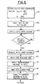
- Figs. 5 and 6 illustrate a high level flow diagram of the measurement process utilized by the system of Fig. 4.
- Electrode 12 is termed the "working" electrode and is preferably comprised of platinum, palladium, or other noble metal.
- Electrode 14 is a reference electrode and is preferably comprised of silver/silver oxide or silver/silver chloride. Electrodes 12 and 14 are sandwiched between a pair of polymeric sheet materials 16 and 18 with sheet material 18 having openings 20 and 22 that expose the electrodes. Opening 20 creates, in effect, a reaction zone or "well” wherein a sample of body fluid can be emplaced to enable a reaction to occur. Opening 22 exposes electrodes 12 and 14 so that the test cell 10 may be plugged into a female connector that makes electrical connections to the electrodes.
- a section of test cell 10 is shown.
- a reaction layer 24 is emplaced in well 20 and provides the reactants for the biosensing reaction.
- layer 24 will include an enzyme, an electrolyte, a mediator, certain film formers, and a buffer.
- the enzyme may be glucose oxidase (or glucose dehydrogenase); the buffer may be organic or inorganic; the electrolyte may be potassium chloride or sodium chloride; the mediator is preferably potassium ferricyanide and the film formers comprise gelatin and propiofin.
- the enzyme would preferably be cholesterol oxidase with or without a cholesterol esterase additive.
- the buffer is preferably inorganic and includes an electrolyte such as potassium chloride or sodium chloride. In this case, two mediators are used, i.e. ferricyanide and quinones, and are placed in a gelatin film, as indicated above.
- glucose concentration is determined by initially emplacing in well 20, a sample of blood.
- the glucose within the sample causes a forward reaction of potassium ferricyanide conversion to potassium ferrocyanide.
- a subsequent application of a voltage across terminals 12 and 14 will see the creation of a small current therebetween that results from the reverse reaction of potassium ferrocyanide back to potassium ferricyanide.
- the flow of electrons during the reverse reaction is sensed and measured and has been found to bear a known relationship to glucose concentration levels.
- a chart illustrates the current variations which occur with various levels of glucose concentration. Current in microamperes is plotted along the chart's vertical axis and time is plotted along its horizontal axis. Curves 30, 32, 34, and 36 illustrate the changes of current with the passage of time, after a potential is applied between electrodes 12 and 14 to initiate the reverse reaction. It can be seen that each of those curves follows a different path which is dependent upon the glucose concentration present in the blood sample.
- each of the current curves 30, 32, 34, 36 etc. is described by equation 1. This, of course, assumes that the test conditions are as precisely defined and followed. Since the test cell of Fig. 1 and its allied measuring instrument (to be hereinafter to be described with respect to Fig. 4) are designed to be used by other than skilled technicians, it may often occur that the required test conditions are not met. For instance, it is critical that the blood sample be properly emplaced within well 20 for the glucose determination to be accurate. If the sample only covers a portion of the electrode areas, an erroneous reading will occur. If there is contamination in well 20 between electrodes 12 and 14, when a voltage is applied thereacross, the current curve which results may have no relationship whatsoever to glucose concentration.
- Equation 5 shows that even though individual measurement currents taken at subsequent measurement times are not known in advance, that the ratio thereof, assuming a Cottrell curve is being followed, will be a constant and will show a level of similarity with the ratio of the square roots of the measurement times. Of course, the ratios will rarely be exactly alike as the current measurements will show some variations due to test conditions. As a result, any comparison of the ratios will require that standard deviations be taken into account when the comparison is made.
- FIG. 4 a high level block diagram of the biosensing instrument is illustrated.
- Overall system control emanates from microprocessor 50 via system bus 52.
- System communications occur over system bus 52 and each of the operating units within the instrument interface therethrough.
- a signal voltage module 54 converts digital commands from microprocessor 50 into analog outputs which are then applied to cell 10 via line 56. (It should be remembered that cell 10, in an actual embodiment, is pluggable and only experiences stimulus voltages from signal voltage module 54 when it is inserted into a female plug.)
- Signal detector 60 which, in turn, measures the current on a continuing basis and converts the readings to digital outputs.
- Signal detector 60 is controlled by a clock input from microprocessor 50 and, when a test voltage is applied to cell 10, it begins providing current readings on continuing basis. For instance, while the reverse reaction may take up 10 seconds to complete, signal detection module 60 will, during these 10 seconds, be taking current reading once every 500 milliseconds.
- Random access memories (RAM's) 62 and 64 provide the operating memory for the instrument.
- RAM 62 provides storage for operating parameters.
- RAM 64 provides additional storage which enables previous measurement cycles to be retained for comparison purposes or for later read-out to another processor via input/output port 66.
- a pluggable read-only-memory (ROM) 68 interfaces with bus 52, and in addition to other data, contains precalculated comparison constants (x 1,2 , X 2,3 etc.) for the batch of test cells from which test cell 10 is taken.
- Program ROM 72 contains the software to operate the microprocessor.
- a Cottrell current measurement taken at a single measurement time bears a linear relationship to glucose concentration. The linear relationship may, however, vary somewhat with different batches of cells.
- ROM 68 can be supplied along with a batch of cells and will further include calibration constants to enable the linear relationship between Cottrell current and concentration, for the specific batch of cells, to be precisely defined for microprocessor 50.
- a display 70 enables the user to see the results of a concentration measurement taken through the use of cell 10.
- microprocessor 50 causes signal voltage module 54 to apply a measurement potential to cell 10 to commence the reverse reaction. Again, there is an initial surge of current which is ignored by the measurement circuitry. At the end of the surge time (e.g., t0), an initial current measurement is taken, followed by subsequent measurements at subsequent intervals (e.g. t1, t2, t3). As will be hereinafter understood, microprocessor 50 selects one of the current measurements and calculates the glucose concentration based upon the linear relationship which has been precalibrated using the constants provided by ROM 68.
- microprocessor 50 accumulates all of the current measurement values; and integrates them over the measurement time to obtain a value for the total charge transferred during the reverse reaction. This value is converted to concentration to provide a comparative value to the single measurement value. Additionally, microprocessor 50, in combination with the other modules in the system, carries out a series of tests to determine that the signals being detected by signal detector 60 are following the Cottrell current relationship.
- each of the precalculated comparison ratios (x 1,2 , x 2,3 etc.) is accessed (box 100) and stored.
- a comparison ratio x n, n+1 is accessed and stored.
- the user inserts the test cell and depresses the test key.
- the system's circuits are then initialized (box 102) and the autodrop voltage is applied to cell 10 (box 104).
- Signal detector 60 then awaits a current spike indicating that a blood sample has been placed in well 20 (box 106). If no current spike is detected, the program simply recycles until the current spike is sensed (box 106). At this point, the autodrop voltage is removed (box 108), and the system waits until the reaction time expires (box 110).
- a measurement voltage is applied to cell 10 from signal voltage module 54, and a first current reading is taken at t0 and recorded (box 116).
- a subsequent current reading is taken (e.g. t1) and recorded (box 118).
- the current value measured at t n and t n+1 are accessed and the ratio thereof is derived. That ratio is then compared to the prestored comparison constant x n, n+1 . If the ratios are not "similar”, then it is known that the measured values of current are not following a predetermined Cottrell current relationship. By the term “similar” is meant that the calculated current ratio does not differ from the precalculated comparison constant x by more than a predetermined error value (box 120).
- the ratio of i tn to i tn+1 is then calculated and compared to the prestored comparison constant, etc. It should be understood that the comparison constants need not be calculated for just those current ratios taken at succeeding measurement times, but may be calculated for various diverse measurement times.
- the system computes the integral glucose concentration (box 130) and the sampled glucose concentration (134). The system then compares the calculated integrated and sampled glucose concentrations (box 136) and determines whether they are similar or not (box 138) with the results being as shown in boxes 140 or 142.
Abstract
Description
- This invention relates to a biosensing instrument for quantitatively determining the concentration of an analyte in a fluid sample, and more particularly, to a method and apparatus for amperometrically determining the concentration of biological compounds, such as glucose, cholesterol, etc., in a body fluid such as blood.
- This invention is related to inventions described in: U.S. Patent 5,963,814 , filed 15 December 1989, entitled "Regulated Bifurcated Power Supply" by Parks and White.
- U.S. Patent 4,999,632 filed 15 December 1989, entitled "Analog to Digital Conversion With Noise Reduction" by Parks.
- U.S. Patent 4,999,582 filed 15 December 1989, entitled "Biosensor Electrode Excitation Circuit" by Parks and White.
- Recently, biosensors employing enzymes have been applied to the detection of both glucose and cholesterol concentrations in blood samples. In European Patent Application 0 230 472 to Nankai et al., a biosensing instrument is disclosed which employs amperometric measurements to determine glucose concentration in a blood sample. The instrument employs a test cell with measuring, reference and counter electrodes. Overlaying the electrodes is an insert which contains glucose oxidase, potassium ferricyanide and other components. When a blood sample is placed in contact with the insert, glucose in the sample reacts with the potassium ferricyanide (through the action of the glucose oxidase) to form potassium ferrocyanide. A subsequent application of a voltage to the electrodes induces a reversal of the reaction and a current flow which is proportional to the concentration of the potassium ferrocyanide formed in the initial reaction. A measure of the current flow is said to correspond to the concentration of glucose in the sample.
- A similar system for measuring both glucose and cholesterol concentrations is disclosed in PCT International Application No. WO 89/08713 of Pottgen et al. Both the Nankai et al. and the Pottgen et al. systems employ similar chemistries to enable amperometric detection of glucose concentrations. For glucose, both rely upon the catalytic action of glucose oxidase on glucose to enable the conversion of potassium ferricyanide (+ 3) to potassium ferrocyanide (+ 4), (i.e., the "forward" reaction). A subsequent application of a potential across the reactants electrochemically causes a reversal of the reaction, (i.e. the "reverse" reaction). Upon the oxidation of glucose by glucose oxidase, electrons are transferred to ferricyanide causing its reduction yielding ferrocyanide. An applied potential to the electrode electrochemically oxidizes ferrocyanide back to ferricyanide with the electrons transferred to the electrode. This creates a small and detectable electrical current whose level is proportional to the level of glucose concentration in the sample. The current which results during the reverse reaction is known as the Cottrell current and is described by the following equation:
- n =
- the number of transferred electrons;
- F =
- Faraday's constant
- A =
- area of measuring electrode;
- C =
- concentration of the analyte;
- D =
- diffusion coefficient of the electroactive species;
- t =
- time
- Equation 1 can be reduced to a simpler expression by realizing that most of the factors in the equation are constants for any particular test system. Thus, the Cottrell current, at any particular time during the reverse reaction, is shown by the following:
A Equation 2 indicates that the Cottrell current is proportional to the concentration of the analyte and is inversely proportional to the square root of the measurement time. Plots of Cottrell current variations at various glucose concentration levels, are shown by the curves in the right upper quadrant of Fig. 3. - The prior art has characteristically selected a particular time during the reverse reaction to obtain a reading of the Cottrell current and converted that reading into a measure of glucose or cholesterol concentration. Neither Nankai et al. or Pottgen et al. deal with certain real-life problems which occur during the use of a test cell. For instance, if the blood sample does not totally cover the sensing electrode surfaces, an erroneous reading results. Furthermore, if the reaction area becomes hydrated, either prior to or during the test, an erroneous reading occurs. Likewise, if there is leakage along the length of the electrodes so that the blood sample covers not only the portion of the electrodes in the reaction zone, but also outside of the reaction zone, again, erroneous readings will occur. These errors appear as baseline shifts in the Cottrell current or modulations of area during the measurement period.
- Accordingly, it is an object of this invention to provide an amperometric biosensor and method which both provides analyte concentration readings and prevents erroneous readings from being reported as true.
- It is another object of this invention to provide an amperometric biosensor and method for glucose concentration which provides an error indication, if an aberrant current curve results.
- A biosensing system is described which determines whether a measured current is varying in accordance with a predetermined Cottrell current relationship. The system includes a test cell with at least a pair of electrodes which extend into a reaction zone, which reaction zone includes analyte reactants. An analog signal detector, in combination with a microprocessor, take plurality of current measurements between the electrodes over a plurality of succeeding measurement times, after a sample is placed in contact with the analyte reactants in the reaction zone. The microprocessor also stores a plurality of succeeding comparison constants which are derived by taking the inverse ratio of the square root of a measurement time divided by the square root of a subsequent measurement time. The microprocessor selects a pair of succeeding measurement times; derives a ratio of the currents measured at those times; and then compares the ratio of those currents with the comparison constant previously derived for the pair of succeeding measurement times. If the comparison indicates that the measured current ratio is dissimilar from the comparison constant, an indication is developed that the current between the electrodes is not varying in accordance with the Cottrell relationship.
- The invention also concerns the methods disclosed in
claims 4 and 9. - Fig. 1 is a perspective view of a test cell used with the biosensing instrument.
- Fig. 2 is a section taken along line 2-2, in Fig. 1.
- Fig. 3 is a chart showing variations of current over time which result when various concentrations of glucose are present in the test cell of Fig. 1.
- Fig. 4 is a block diagram of the test system used to determine the concentration of an analyte in a fluid sample.
- Figs. 5 and 6 illustrate a high level flow diagram of the measurement process utilized by the system of Fig. 4.
- Referring now to Fig. 1, a
pluggable test cell 10 includes a pair ofelectrodes Electrode 14 is a reference electrode and is preferably comprised of silver/silver oxide or silver/silver chloride.Electrodes polymeric sheet materials sheet material 18 havingopenings Opening 20 creates, in effect, a reaction zone or "well" wherein a sample of body fluid can be emplaced to enable a reaction to occur.Opening 22 exposeselectrodes test cell 10 may be plugged into a female connector that makes electrical connections to the electrodes. - In Fig. 2, a section of
test cell 10 is shown. During manufacture, areaction layer 24 is emplaced in well 20 and provides the reactants for the biosensing reaction. If the instrument is to be used for glucose concentration determinations,layer 24 will include an enzyme, an electrolyte, a mediator, certain film formers, and a buffer. For instance, the enzyme may be glucose oxidase (or glucose dehydrogenase); the buffer may be organic or inorganic; the electrolyte may be potassium chloride or sodium chloride; the mediator is preferably potassium ferricyanide and the film formers comprise gelatin and propiofin. If the test cell is to be employed for cholesterol concentration determination, the enzyme would preferably be cholesterol oxidase with or without a cholesterol esterase additive. The buffer is preferably inorganic and includes an electrolyte such as potassium chloride or sodium chloride. In this case, two mediators are used, i.e. ferricyanide and quinones, and are placed in a gelatin film, as indicated above. - As stated in the introduction hereto, the chemistries employed by this system are known in the art and will not be described in significant detail. Suffice to say that glucose concentration is determined by initially emplacing in well 20, a sample of blood. The glucose within the sample causes a forward reaction of potassium ferricyanide conversion to potassium ferrocyanide. When the forward reaction has proceeded to completion, a subsequent application of a voltage across
terminals - In Fig. 3, a chart illustrates the current variations which occur with various levels of glucose concentration. Current in microamperes is plotted along the chart's vertical axis and time is plotted along its horizontal axis.
Curves electrodes - As above described, the shape of each of the
current curves electrodes sheets 16 and 18 (e.g. along the sides ofconductors 12 or 14), an erroneous reading will occur. The prior art test cells which have employed Cottrell current measurements have not taken these problems into account and have assumed, that with one measurement, the Cottrell current/time relationship is obtained. - While the above problem could be overcome by including a complex curve fitting algorithm into the microprocessor that controls the instrument, a much simpler and less complex technique for providing failsafe measurement indications has been found. As can be seen from
equation 2, the Cottrell current at any time is inversely proportional to the square root of the time at which the measurement is taken. Thus, Cottrell current measurements taken at two succeeding measurement times tl and t2 can be expressed as: - The ratio of the measured Cottrell currents can be expressed as:
- From equation 5, it can be seen that the ratio (e.g. X1,2) of Cottrell currents measured at two succeeding times (e.g., t1, t2), is the same as the inverse of the ratio of the square roots of the times at which the measurements were taken. Thus the inverse ratio of the time square roots (designated as x1,2 or "comparison ratio") is, for all glucose concentration curves, a constant.
- Equation 5 shows that even though individual measurement currents taken at subsequent measurement times are not known in advance, that the ratio thereof, assuming a Cottrell curve is being followed, will be a constant and will show a level of similarity with the ratio of the square roots of the measurement times. Of course, the ratios will rarely be exactly alike as the current measurements will show some variations due to test conditions. As a result, any comparison of the ratios will require that standard deviations be taken into account when the comparison is made.
- Turning now to Fig. 4, a high level block diagram of the biosensing instrument is illustrated. Overall system control emanates from
microprocessor 50 viasystem bus 52. System communications occur oversystem bus 52 and each of the operating units within the instrument interface therethrough. Asignal voltage module 54 converts digital commands frommicroprocessor 50 into analog outputs which are then applied tocell 10 vialine 56. (It should be remembered thatcell 10, in an actual embodiment, is pluggable and only experiences stimulus voltages fromsignal voltage module 54 when it is inserted into a female plug.) - Current flow is returned through
cell 10, viaconductor 58, bysignal detector 60 which, in turn, measures the current on a continuing basis and converts the readings to digital outputs.Signal detector 60 is controlled by a clock input frommicroprocessor 50 and, when a test voltage is applied tocell 10, it begins providing current readings on continuing basis. For instance, while the reverse reaction may take up 10 seconds to complete,signal detection module 60 will, during these 10 seconds, be taking current reading once every 500 milliseconds. - Random access memories (RAM's) 62 and 64 provide the operating memory for the instrument.
RAM 62 provides storage for operating parameters.RAM 64 provides additional storage which enables previous measurement cycles to be retained for comparison purposes or for later read-out to another processor via input/output port 66. A pluggable read-only-memory (ROM) 68 interfaces withbus 52, and in addition to other data, contains precalculated comparison constants (x1,2, X2,3 etc.) for the batch of test cells from which testcell 10 is taken.Program ROM 72 contains the software to operate the microprocessor. Likewise, it is known that a Cottrell current measurement taken at a single measurement time bears a linear relationship to glucose concentration. The linear relationship may, however, vary somewhat with different batches of cells. Therefore,ROM 68, can be supplied along with a batch of cells and will further include calibration constants to enable the linear relationship between Cottrell current and concentration, for the specific batch of cells, to be precisely defined formicroprocessor 50. Finally, adisplay 70 enables the user to see the results of a concentration measurement taken through the use ofcell 10. - The overall operation of a system can be understood by examining Fig. 3 in combination with Fig. 4. Initially,
cell 10 is plugged into the instrument, and the user depresses a key (not shown) to indicate that the test is about to begin.Microprocessor 50 then causessignal voltage module 54 to apply an "autodrop" potential to the cell vialine 56. Then, when a sample or "drop" of blood is placed in well 20, an immediate spike of current occurs, indicating the presence of the blood sample, and is sensed by asignal detector module 60. That current spike is indicated bycurve 80 in Fig. 3. Upon sensingcurrent spike 80,microprocessor 50 causes signalvoltage module 54 to remove the autodrop potential fromline 56. - At this point, the forward reaction commences and continues until completion (e.g. some 20 seconds). At the end of the forward reaction time,
microprocessor 50 causes signalvoltage module 54 to apply a measurement potential tocell 10 to commence the reverse reaction. Again, there is an initial surge of current which is ignored by the measurement circuitry. At the end of the surge time (e.g., t0), an initial current measurement is taken, followed by subsequent measurements at subsequent intervals (e.g. t1, t2, t3...). As will be hereinafter understood,microprocessor 50 selects one of the current measurements and calculates the glucose concentration based upon the linear relationship which has been precalibrated using the constants provided byROM 68. Additionally,microprocessor 50 accumulates all of the current measurement values; and integrates them over the measurement time to obtain a value for the total charge transferred during the reverse reaction. This value is converted to concentration to provide a comparative value to the single measurement value. Additionally,microprocessor 50, in combination with the other modules in the system, carries out a series of tests to determine that the signals being detected bysignal detector 60 are following the Cottrell current relationship. - These procedures are described in Figs. 5 and 6. Initially, each of the precalculated comparison ratios (x1,2, x2,3 etc.) is accessed (box 100) and stored. Thus, for each of a plurality of measurement times tn, tn+1, a comparison ratio xn, n+1 is accessed and stored. Next, the user inserts the test cell and depresses the test key. The system's circuits are then initialized (box 102) and the autodrop voltage is applied to cell 10 (box 104).
Signal detector 60 then awaits a current spike indicating that a blood sample has been placed in well 20 (box 106). If no current spike is detected, the program simply recycles until the current spike is sensed (box 106). At this point, the autodrop voltage is removed (box 108), and the system waits until the reaction time expires (box 110). - Then, a measurement voltage is applied to
cell 10 fromsignal voltage module 54, and a first current reading is taken at t0 and recorded (box 116). Next, (in Fig. 6) a subsequent current reading is taken (e.g. t1) and recorded (box 118). - At this point, the current value measured at tn and tn+1 are accessed and the ratio thereof is derived. That ratio is then compared to the prestored comparison constant xn, n+1. If the ratios are not "similar", then it is known that the measured values of current are not following a predetermined Cottrell current relationship. By the term "similar" is meant that the calculated current ratio does not differ from the precalculated comparison constant x by more than a predetermined error value (box 120).
- In the event the comparison "fails", an error condition is reported (box 122). If the comparison succeeds, the process continues with
microprocessor 50 integrating the current values taken at tn and tn+1 over the time period (tn+1) - (tn), and accumulating the value, (it being remembered that the integration of current over time gives a value of charge transfer during that time, see box 126). At some time during the measurement cycle, a sample measurement time is designated. At such time, the current reading taken at that time (box 127) is subsequently converted to a "sample" glucose concentration value (box 134). - A determination is then made as to whether the system has arrived at the last time value in the measurement cycle (box 128). If not, the system recycles back to
box 118 after incrementing n (box 124) and takes the next current reading at the next time. The ratio of itn to itn+1 is then calculated and compared to the prestored comparison constant, etc. It should be understood that the comparison constants need not be calculated for just those current ratios taken at succeeding measurement times, but may be calculated for various diverse measurement times. - When it has been determined that the last current value has been measured (box 128), the system computes the integral glucose concentration (box 130) and the sampled glucose concentration (134). The system then compares the calculated integrated and sampled glucose concentrations (box 136) and determines whether they are similar or not (box 138) with the results being as shown in
boxes - From the above it can be seen that, in addition to taking a single sample measurement, an integrated sample measurement is derived to enable a comparison to be made to assure that the reading can be relied upon. Furthermore, the comparison of the current ratios with the predetermined comparison constants enables the system to precisely determine that the measured current values have followed an expected Cottrell current relationship. Thus, if there is an aberration in the test system or in the cell, erroneous readings are avoided.
- It should be understood that the foregoing description is only illustrative of the invention. Various alternatives and modifications can be devised by those skilled in the art without departing from the invention. Accordingly, the present invention is intended to embrace all such alternatives, modifications and variances which fall within the scope of the appended claims.
Claims (10)
- A biosensor system for determining whether a current through a reaction zone is varying in accordance with a predetermined Cottrell current relationship, comprising:a test cell (10) including electrode means (12,14) and a reaction zone with analyte reactant;means (60,50) for obtaining a plurality of readings of current in said reaction zone over a plurality of measurement times, after a sample containing an analyte is placed in said reaction zone;means (68) for storing at least a comparison constant for a pair of succeeding measurement times, said comparison constant evidencing the inverse ratio of the square root of a measurement time divided by the square root of a subsequent measurement time;means (50) for deriving a ratio of the current readings obtained at said pair of succeeding measurement times; andmeans (50) for comparing and indicating whether said ratio of said current readings and said comparison constant for said pair of succeeding measurement times are similar.
- The system as defined in claim 1 wherein: said storing means includes a plurality of comparison constants for a plurality of succeeding measurement times; and said deriving means derives ratios of current readings taken at said succeeding measurement times, and said comparison means compares said ratios with corresponding comparison constants, whereby said system determines if said current readings are following said Cottrell current relationship.
- The system as defined in claim 2 wherein said test cell includes two electrodes (12,14) which extend into a reaction zone, said electrodes covered by an analyte reactant containing layer (24).
- In a system for measuring a current i passing through a reaction zone, which current, in dependence upon the concentration of an analyte in the reaction zone, changes to follow one of a family of curves whose shape is defined by the Cottrell equation, a method for determining that said current is changing in accordance with the Cottrell equation, comprising the steps of:(a) measuring said current i at a plurality of measurement times tn, tn+1, tn+2... to derive current values in, in+1, in+2 ...;(b) calculating at least the value of the ratio of(c) calculating the value of the ratio of in / in+1(d) comparing the comparison constant calculated in step b and with the ratio calculated in step c; and(e) if said comparison indicates a dissimilarity, providing a signal indicating that said measured current is not changing in accordance with said Cottrell equation.
- The method as defined in claim 4 wherein the ratio defined in step b is calculated for a plurality measurement times to obtain a plurality of comparison constants.
- The method as defined in claim 5 wherein a ratio, as defined in step c, is calculated for currents measured at each of the measurement times which are used to derive the comparison constants of claim 6.
- The method of claim 6 wherein step d compares the comparison constants with ratios derived in step c for corresponding measurement times and step (e) provides a signal if any of said comparisons indicate a dissimilarity.
- The method of claim 7 wherein said comparison constants step b are precalculated and stored.
- In a system for measuring a current i passing through a reaction zone, which current i, in dependence upon the concentration of an analyte in the reaction zone, changes to follow one of a family of curves defined by the Cottrell equation which are indicative of a level of concentration of said analyte, a method for assuring the accuracy of a measure of concentration of said analyte taken during a measurement period comprising the steps of:(a) measuring the value of said current i at a predetermined time in said measurement period;(b) measuring the value of said current i at a plurality of measurement times during said measurement period;(c) integrating said current values over said successive measurement times to derive an indication of total charge transfer during said measurement times; and(a) providing an indication of error if said values derived in steps b and c result in dissimilar analyte concentration values.
- The method of claim 9 wherein step d includes the steps of:d1) converting the measured value of said current i taken in step a to an analyte concentration value;d2) converting said total charge transfer indication to an analyte concentration value, andd3) comparing the concentration values from steps d1 and d2 to determine if they are dissimilar.
Applications Claiming Priority (3)
| Application Number | Priority Date | Filing Date | Title |
|---|---|---|---|
| US451309 | 1982-12-20 | ||
| US07/451,309 US5243516A (en) | 1989-12-15 | 1989-12-15 | Biosensing instrument and method |
| PCT/US1990/007504 WO1991009373A1 (en) | 1989-12-15 | 1990-12-14 | Biosensing instrument and method |
Publications (3)
| Publication Number | Publication Date |
|---|---|
| EP0505475A1 EP0505475A1 (en) | 1992-09-30 |
| EP0505475A4 EP0505475A4 (en) | 1995-03-29 |
| EP0505475B1 true EP0505475B1 (en) | 1999-03-03 |
Family
ID=23791703
Family Applications (1)
| Application Number | Title | Priority Date | Filing Date |
|---|---|---|---|
| EP91901998A Expired - Lifetime EP0505475B1 (en) | 1989-12-15 | 1990-12-14 | Biosensing instrument and method |
Country Status (8)
| Country | Link |
|---|---|
| US (1) | US5243516A (en) |
| EP (1) | EP0505475B1 (en) |
| JP (1) | JP2651278B2 (en) |
| AT (1) | ATE177224T1 (en) |
| CA (1) | CA2071484C (en) |
| DE (1) | DE69032977T2 (en) |
| ES (1) | ES2134193T3 (en) |
| WO (1) | WO1991009373A1 (en) |
Cited By (56)
| Publication number | Priority date | Publication date | Assignee | Title |
|---|---|---|---|---|
| DE19946059A1 (en) * | 1999-09-25 | 2001-03-29 | Roche Diagnostics Gmbh | System for the transdermal production of body fluid |
| EP1672364A1 (en) | 2004-12-15 | 2006-06-21 | F. Hoffmann-La Roche AG | Analytical system for analysis of a liquid sample by means of a test element. |
| EP2000799A1 (en) | 2005-10-25 | 2008-12-10 | Roche Diagnostics GmbH | Analysis device for analysing a sample on a test element |
| US7648468B2 (en) | 2002-04-19 | 2010-01-19 | Pelikon Technologies, Inc. | Method and apparatus for penetrating tissue |
| US7666149B2 (en) | 1997-12-04 | 2010-02-23 | Peliken Technologies, Inc. | Cassette of lancet cartridges for sampling blood |
| US7674232B2 (en) | 2002-04-19 | 2010-03-09 | Pelikan Technologies, Inc. | Method and apparatus for penetrating tissue |
| US7682318B2 (en) | 2001-06-12 | 2010-03-23 | Pelikan Technologies, Inc. | Blood sampling apparatus and method |
| US7699791B2 (en) | 2001-06-12 | 2010-04-20 | Pelikan Technologies, Inc. | Method and apparatus for improving success rate of blood yield from a fingerstick |
| US7708701B2 (en) | 2002-04-19 | 2010-05-04 | Pelikan Technologies, Inc. | Method and apparatus for a multi-use body fluid sampling device |
| US7717863B2 (en) | 2002-04-19 | 2010-05-18 | Pelikan Technologies, Inc. | Method and apparatus for penetrating tissue |
| US7731729B2 (en) | 2002-04-19 | 2010-06-08 | Pelikan Technologies, Inc. | Method and apparatus for penetrating tissue |
| US7749174B2 (en) | 2001-06-12 | 2010-07-06 | Pelikan Technologies, Inc. | Method and apparatus for lancet launching device intergrated onto a blood-sampling cartridge |
| US7754152B2 (en) | 2004-12-15 | 2010-07-13 | Roche Diagnostics Operations, Inc. | Electrical connection system for electrochemical analysis system |
| US7780631B2 (en) | 1998-03-30 | 2010-08-24 | Pelikan Technologies, Inc. | Apparatus and method for penetration with shaft having a sensor for sensing penetration depth |
| US7822454B1 (en) | 2005-01-03 | 2010-10-26 | Pelikan Technologies, Inc. | Fluid sampling device with improved analyte detecting member configuration |
| US7833171B2 (en) | 2002-04-19 | 2010-11-16 | Pelikan Technologies, Inc. | Method and apparatus for penetrating tissue |
| US7850622B2 (en) | 2001-06-12 | 2010-12-14 | Pelikan Technologies, Inc. | Tissue penetration device |
| US7850621B2 (en) | 2003-06-06 | 2010-12-14 | Pelikan Technologies, Inc. | Method and apparatus for body fluid sampling and analyte sensing |
| US7862520B2 (en) | 2002-04-19 | 2011-01-04 | Pelikan Technologies, Inc. | Body fluid sampling module with a continuous compression tissue interface surface |
| US7874994B2 (en) | 2002-04-19 | 2011-01-25 | Pelikan Technologies, Inc. | Method and apparatus for penetrating tissue |
| US7892185B2 (en) | 2002-04-19 | 2011-02-22 | Pelikan Technologies, Inc. | Method and apparatus for body fluid sampling and analyte sensing |
| US7892183B2 (en) | 2002-04-19 | 2011-02-22 | Pelikan Technologies, Inc. | Method and apparatus for body fluid sampling and analyte sensing |
| US7901365B2 (en) | 2002-04-19 | 2011-03-08 | Pelikan Technologies, Inc. | Method and apparatus for penetrating tissue |
| US7901362B2 (en) | 2002-04-19 | 2011-03-08 | Pelikan Technologies, Inc. | Method and apparatus for penetrating tissue |
| US7909777B2 (en) | 2002-04-19 | 2011-03-22 | Pelikan Technologies, Inc | Method and apparatus for penetrating tissue |
| US7909778B2 (en) | 2002-04-19 | 2011-03-22 | Pelikan Technologies, Inc. | Method and apparatus for penetrating tissue |
| US7914465B2 (en) | 2002-04-19 | 2011-03-29 | Pelikan Technologies, Inc. | Method and apparatus for penetrating tissue |
| US7976476B2 (en) | 2002-04-19 | 2011-07-12 | Pelikan Technologies, Inc. | Device and method for variable speed lancet |
| US7988645B2 (en) | 2001-06-12 | 2011-08-02 | Pelikan Technologies, Inc. | Self optimizing lancing device with adaptation means to temporal variations in cutaneous properties |
| US8007446B2 (en) | 2002-04-19 | 2011-08-30 | Pelikan Technologies, Inc. | Method and apparatus for penetrating tissue |
| US8079960B2 (en) | 2002-04-19 | 2011-12-20 | Pelikan Technologies, Inc. | Methods and apparatus for lancet actuation |
| US8197421B2 (en) | 2002-04-19 | 2012-06-12 | Pelikan Technologies, Inc. | Method and apparatus for penetrating tissue |
| US8221334B2 (en) | 2002-04-19 | 2012-07-17 | Sanofi-Aventis Deutschland Gmbh | Method and apparatus for penetrating tissue |
| US8262614B2 (en) | 2003-05-30 | 2012-09-11 | Pelikan Technologies, Inc. | Method and apparatus for fluid injection |
| US8267870B2 (en) | 2002-04-19 | 2012-09-18 | Sanofi-Aventis Deutschland Gmbh | Method and apparatus for body fluid sampling with hybrid actuation |
| US8282576B2 (en) | 2003-09-29 | 2012-10-09 | Sanofi-Aventis Deutschland Gmbh | Method and apparatus for an improved sample capture device |
| US8337421B2 (en) | 2001-06-12 | 2012-12-25 | Sanofi-Aventis Deutschland Gmbh | Tissue penetration device |
| US8360992B2 (en) | 2002-04-19 | 2013-01-29 | Sanofi-Aventis Deutschland Gmbh | Method and apparatus for penetrating tissue |
| US8435190B2 (en) | 2002-04-19 | 2013-05-07 | Sanofi-Aventis Deutschland Gmbh | Method and apparatus for penetrating tissue |
| US8556829B2 (en) | 2002-04-19 | 2013-10-15 | Sanofi-Aventis Deutschland Gmbh | Method and apparatus for penetrating tissue |
| US8574895B2 (en) | 2002-12-30 | 2013-11-05 | Sanofi-Aventis Deutschland Gmbh | Method and apparatus using optical techniques to measure analyte levels |
| US8641644B2 (en) | 2000-11-21 | 2014-02-04 | Sanofi-Aventis Deutschland Gmbh | Blood testing apparatus having a rotatable cartridge with multiple lancing elements and testing means |
| US8668656B2 (en) | 2003-12-31 | 2014-03-11 | Sanofi-Aventis Deutschland Gmbh | Method and apparatus for improving fluidic flow and sample capture |
| US8702624B2 (en) | 2006-09-29 | 2014-04-22 | Sanofi-Aventis Deutschland Gmbh | Analyte measurement device with a single shot actuator |
| US8721671B2 (en) | 2001-06-12 | 2014-05-13 | Sanofi-Aventis Deutschland Gmbh | Electric lancet actuator |
| US8784335B2 (en) | 2002-04-19 | 2014-07-22 | Sanofi-Aventis Deutschland Gmbh | Body fluid sampling device with a capacitive sensor |
| US8828203B2 (en) | 2004-05-20 | 2014-09-09 | Sanofi-Aventis Deutschland Gmbh | Printable hydrogels for biosensors |
| US8965476B2 (en) | 2010-04-16 | 2015-02-24 | Sanofi-Aventis Deutschland Gmbh | Tissue penetration device |
| US9144401B2 (en) | 2003-06-11 | 2015-09-29 | Sanofi-Aventis Deutschland Gmbh | Low pain penetrating member |
| US9226699B2 (en) | 2002-04-19 | 2016-01-05 | Sanofi-Aventis Deutschland Gmbh | Body fluid sampling module with a continuous compression tissue interface surface |
| US9248267B2 (en) | 2002-04-19 | 2016-02-02 | Sanofi-Aventis Deustchland Gmbh | Tissue penetration device |
| US9314194B2 (en) | 2002-04-19 | 2016-04-19 | Sanofi-Aventis Deutschland Gmbh | Tissue penetration device |
| US9351680B2 (en) | 2003-10-14 | 2016-05-31 | Sanofi-Aventis Deutschland Gmbh | Method and apparatus for a variable user interface |
| US9375169B2 (en) | 2009-01-30 | 2016-06-28 | Sanofi-Aventis Deutschland Gmbh | Cam drive for managing disposable penetrating member actions with a single motor and motor and control system |
| US9386944B2 (en) | 2008-04-11 | 2016-07-12 | Sanofi-Aventis Deutschland Gmbh | Method and apparatus for analyte detecting device |
| US9775553B2 (en) | 2004-06-03 | 2017-10-03 | Sanofi-Aventis Deutschland Gmbh | Method and apparatus for a fluid sampling device |
Families Citing this family (136)
| Publication number | Priority date | Publication date | Assignee | Title |
|---|---|---|---|---|
| US5385846A (en) * | 1993-06-03 | 1995-01-31 | Boehringer Mannheim Corporation | Biosensor and method for hematocrit determination |
| US5366609A (en) † | 1993-06-08 | 1994-11-22 | Boehringer Mannheim Corporation | Biosensing meter with pluggable memory key |
| US6153069A (en) * | 1995-02-09 | 2000-11-28 | Tall Oak Ventures | Apparatus for amperometric Diagnostic analysis |
| US5695949A (en) * | 1995-04-07 | 1997-12-09 | Lxn Corp. | Combined assay for current glucose level and intermediate or long-term glycemic control |
| US6413410B1 (en) | 1996-06-19 | 2002-07-02 | Lifescan, Inc. | Electrochemical cell |
| AUPN363995A0 (en) * | 1995-06-19 | 1995-07-13 | Memtec Limited | Electrochemical cell |
| US6863801B2 (en) | 1995-11-16 | 2005-03-08 | Lifescan, Inc. | Electrochemical cell |
| AUPN661995A0 (en) | 1995-11-16 | 1995-12-07 | Memtec America Corporation | Electrochemical cell 2 |
| US5824491A (en) * | 1996-05-17 | 1998-10-20 | Mercury Diagnostics, Inc. | Dry reagent test strip comprising benzidine dye precursor and antipyrine compound |
| DE19781229C2 (en) * | 1996-06-17 | 2002-02-28 | Mercury Diagnostics Inc | Electrochemical test device and method for its production |
| US6632349B1 (en) * | 1996-11-15 | 2003-10-14 | Lifescan, Inc. | Hemoglobin sensor |
| US6027459A (en) * | 1996-12-06 | 2000-02-22 | Abbott Laboratories | Method and apparatus for obtaining blood for diagnostic tests |
| US7220550B2 (en) * | 1997-05-14 | 2007-05-22 | Keensense, Inc. | Molecular wire injection sensors |
| US6060327A (en) | 1997-05-14 | 2000-05-09 | Keensense, Inc. | Molecular wire injection sensors |
| US6699667B2 (en) | 1997-05-14 | 2004-03-02 | Keensense, Inc. | Molecular wire injection sensors |
| US6001239A (en) | 1998-09-30 | 1999-12-14 | Mercury Diagnostics, Inc. | Membrane based electrochemical test device and related methods |
| US5997817A (en) | 1997-12-05 | 1999-12-07 | Roche Diagnostics Corporation | Electrochemical biosensor test strip |
| US7494816B2 (en) * | 1997-12-22 | 2009-02-24 | Roche Diagnostic Operations, Inc. | System and method for determining a temperature during analyte measurement |
| CN1598564B (en) | 1997-12-22 | 2010-04-21 | 罗赫诊断手术公司 | Meter |
| US8071384B2 (en) | 1997-12-22 | 2011-12-06 | Roche Diagnostics Operations, Inc. | Control and calibration solutions and methods for their use |
| NL1008411C2 (en) * | 1998-02-25 | 1999-08-26 | Technologiestichting Stw | Protein sensor cassette and reader therefor. |
| EP1081490B1 (en) | 1998-05-20 | 2004-09-08 | ARKRAY, Inc. | Method and apparatus for electrochemical measurement using statistical technique |
| ES2179660T3 (en) | 1998-06-01 | 2003-01-16 | Roche Diagnostics Corp | CONJUGATES OF REVERSIBLE IMIDAZOL-OSMIO COMPLEXES. |
| JP3433789B2 (en) * | 1998-06-11 | 2003-08-04 | 松下電器産業株式会社 | Electrode probe and body fluid testing device provided with the same |
| US6841052B2 (en) | 1999-08-02 | 2005-01-11 | Bayer Corporation | Electrochemical-sensor design |
| US7045054B1 (en) * | 1999-09-20 | 2006-05-16 | Roche Diagnostics Corporation | Small volume biosensor for continuous analyte monitoring |
| US6767440B1 (en) | 2001-04-24 | 2004-07-27 | Roche Diagnostics Corporation | Biosensor |
| US20050103624A1 (en) | 1999-10-04 | 2005-05-19 | Bhullar Raghbir S. | Biosensor and method of making |
| US6645359B1 (en) | 2000-10-06 | 2003-11-11 | Roche Diagnostics Corporation | Biosensor |
| US6413395B1 (en) | 1999-12-16 | 2002-07-02 | Roche Diagnostics Corporation | Biosensor apparatus |
| US6858433B1 (en) * | 2000-04-03 | 2005-02-22 | Roche Diagnostics Operations, Inc. | Biosensor electromagnetic noise cancellation |
| US6413213B1 (en) | 2000-04-18 | 2002-07-02 | Roche Diagnostics Corporation | Subscription based monitoring system and method |
| US6428664B1 (en) | 2000-06-19 | 2002-08-06 | Roche Diagnostics Corporation | Biosensor |
| US6488828B1 (en) * | 2000-07-20 | 2002-12-03 | Roche Diagnostics Corporation | Recloseable biosensor |
| US6540890B1 (en) * | 2000-11-01 | 2003-04-01 | Roche Diagnostics Corporation | Biosensor |
| US6814843B1 (en) | 2000-11-01 | 2004-11-09 | Roche Diagnostics Corporation | Biosensor |
| US6447657B1 (en) | 2000-12-04 | 2002-09-10 | Roche Diagnostics Corporation | Biosensor |
| WO2002057768A1 (en) | 2001-01-17 | 2002-07-25 | Arkray, Inc. | Quantitative analyzing method and quantitative analyzer using sensor |
| US6572745B2 (en) * | 2001-03-23 | 2003-06-03 | Virotek, L.L.C. | Electrochemical sensor and method thereof |
| US7473398B2 (en) | 2001-05-25 | 2009-01-06 | Roche Diagnostics Operations, Inc. | Biosensor |
| US9427532B2 (en) | 2001-06-12 | 2016-08-30 | Sanofi-Aventis Deutschland Gmbh | Tissue penetration device |
| US9795747B2 (en) | 2010-06-02 | 2017-10-24 | Sanofi-Aventis Deutschland Gmbh | Methods and apparatus for lancet actuation |
| US6814844B2 (en) | 2001-08-29 | 2004-11-09 | Roche Diagnostics Corporation | Biosensor with code pattern |
| US6755949B1 (en) | 2001-10-09 | 2004-06-29 | Roche Diagnostics Corporation | Biosensor |
| US7431820B2 (en) * | 2001-10-10 | 2008-10-07 | Lifescan, Inc. | Electrochemical cell |
| US7018843B2 (en) * | 2001-11-07 | 2006-03-28 | Roche Diagnostics Operations, Inc. | Instrument |
| US8260393B2 (en) | 2003-07-25 | 2012-09-04 | Dexcom, Inc. | Systems and methods for replacing signal data artifacts in a glucose sensor data stream |
| US8010174B2 (en) | 2003-08-22 | 2011-08-30 | Dexcom, Inc. | Systems and methods for replacing signal artifacts in a glucose sensor data stream |
| US6866758B2 (en) * | 2002-03-21 | 2005-03-15 | Roche Diagnostics Corporation | Biosensor |
| TW559660B (en) * | 2002-06-21 | 2003-11-01 | Apex Biotechnology Corp | Portable multifunctional electrochemical bio-analyzer |
| EP1467206A1 (en) * | 2003-04-08 | 2004-10-13 | Roche Diagnostics GmbH | Biosensor system |
| US8187446B2 (en) * | 2003-06-17 | 2012-05-29 | Chun-Mu Huang | Method of manufacturing a disposable electrochemical sensor strip |
| PT1639352T (en) | 2003-06-20 | 2018-07-09 | Hoffmann La Roche | Method and reagent for producing narrow, homogenous reagent strips |
| US8148164B2 (en) | 2003-06-20 | 2012-04-03 | Roche Diagnostics Operations, Inc. | System and method for determining the concentration of an analyte in a sample fluid |
| US8071030B2 (en) | 2003-06-20 | 2011-12-06 | Roche Diagnostics Operations, Inc. | Test strip with flared sample receiving chamber |
| US7645373B2 (en) | 2003-06-20 | 2010-01-12 | Roche Diagnostic Operations, Inc. | System and method for coding information on a biosensor test strip |
| US7488601B2 (en) | 2003-06-20 | 2009-02-10 | Roche Diagnostic Operations, Inc. | System and method for determining an abused sensor during analyte measurement |
| US7645421B2 (en) | 2003-06-20 | 2010-01-12 | Roche Diagnostics Operations, Inc. | System and method for coding information on a biosensor test strip |
| US8679853B2 (en) | 2003-06-20 | 2014-03-25 | Roche Diagnostics Operations, Inc. | Biosensor with laser-sealed capillary space and method of making |
| US8206565B2 (en) | 2003-06-20 | 2012-06-26 | Roche Diagnostics Operation, Inc. | System and method for coding information on a biosensor test strip |
| JP4874099B2 (en) | 2003-06-20 | 2012-02-08 | エフ ホフマン−ラ ロッシュ アクチェン ゲゼルシャフト | System and method for code information on a biosensor test strip |
| US20070264721A1 (en) * | 2003-10-17 | 2007-11-15 | Buck Harvey B | System and method for analyte measurement using a nonlinear sample response |
| US7718439B2 (en) | 2003-06-20 | 2010-05-18 | Roche Diagnostics Operations, Inc. | System and method for coding information on a biosensor test strip |
| US8058077B2 (en) | 2003-06-20 | 2011-11-15 | Roche Diagnostics Operations, Inc. | Method for coding information on a biosensor test strip |
| US7452457B2 (en) | 2003-06-20 | 2008-11-18 | Roche Diagnostics Operations, Inc. | System and method for analyte measurement using dose sufficiency electrodes |
| ES2392170T3 (en) | 2003-07-01 | 2012-12-05 | F. Hoffmann-La Roche Ag | Electrochemical affinity biosensor system and methods of use |
| GB2404739B (en) * | 2003-08-05 | 2006-04-12 | E2V Tech Uk Ltd | Sensor |
| US20140121989A1 (en) | 2003-08-22 | 2014-05-01 | Dexcom, Inc. | Systems and methods for processing analyte sensor data |
| EP1679510B1 (en) * | 2003-10-29 | 2013-01-16 | ARKRAY, Inc. | Specimen analysis method and specimen analysis device |
| RU2371707C2 (en) | 2004-02-06 | 2009-10-27 | БАЙЕР ХЕЛТКЭР ЭлЭлСи | Electrochemical biosensor |
| RU2006132051A (en) | 2004-02-06 | 2008-03-20 | БАЙЕР ХЕЛТКЭР ЭлЭлСи (US) | OXIDIZABLE COMPOUNDS AS AN INTERNAL STANDARD FOR BIOSENSORS AND METHOD OF APPLICATION |
| WO2005111593A2 (en) * | 2004-02-23 | 2005-11-24 | Douglas Joel S | Strip electrode with conductive nano tube printing |
| EP1765194A4 (en) | 2004-06-03 | 2010-09-29 | Pelikan Technologies Inc | Method and apparatus for a fluid sampling device |
| US7569126B2 (en) | 2004-06-18 | 2009-08-04 | Roche Diagnostics Operations, Inc. | System and method for quality assurance of a biosensor test strip |
| US7601299B2 (en) | 2004-06-18 | 2009-10-13 | Roche Diagnostics Operations, Inc. | System and method for coding information on a biosensor test strip |
| KR100840173B1 (en) * | 2004-06-18 | 2008-06-23 | 에프. 호프만-라 로슈 아게 | System and method for quality assurance of a biosensor test strip |
| CA2973124C (en) | 2004-10-12 | 2020-01-07 | Ascensia Diabetes Care Holdings Ag | Concentration determination in a diffusion barrier layer |
| US7645374B2 (en) | 2005-04-15 | 2010-01-12 | Agamatrix, Inc. | Method for determination of analyte concentrations and related apparatus |
| US7344626B2 (en) * | 2005-04-15 | 2008-03-18 | Agamatrix, Inc. | Method and apparatus for detection of abnormal traces during electrochemical analyte detection |
| US7964089B2 (en) | 2005-04-15 | 2011-06-21 | Agamatrix, Inc. | Analyte determination method and analyte meter |
| US7517439B2 (en) * | 2005-04-15 | 2009-04-14 | Agamatrix, Inc. | Error detection in analyte measurements based on measurement of system resistance |
| US7547382B2 (en) | 2005-04-15 | 2009-06-16 | Agamatrix, Inc. | Determination of partial fill in electrochemical strips |
| GB0509919D0 (en) * | 2005-05-16 | 2005-06-22 | Ralph Ellerker 1795 Ltd | Improvements to door closure system |
| CA2609720C (en) | 2005-07-20 | 2015-06-30 | Bayer Healthcare Llc | Gated amperometry |
| CA2986870A1 (en) | 2005-09-30 | 2007-04-12 | Ascensia Diabetes Care Holdings Ag | Gated voltammetry |
| EP1776925A1 (en) * | 2005-10-20 | 2007-04-25 | Roche Diagnostics GmbH | Analyzing means with lancet and test element |
| EP1813937A1 (en) * | 2006-01-25 | 2007-08-01 | Roche Diagnostics GmbH | Electrochemical biosensor analysis system |
| US8529751B2 (en) * | 2006-03-31 | 2013-09-10 | Lifescan, Inc. | Systems and methods for discriminating control solution from a physiological sample |
| US8398443B2 (en) * | 2006-04-21 | 2013-03-19 | Roche Diagnostics Operations, Inc. | Biological testing system and connector therefor |
| RU2465812C2 (en) * | 2006-05-08 | 2012-11-10 | БАЙЕР ХЕЛТКЭА ЭлЭлСи | System for signal abnormal output signal detection for biosensor |
| TWI317015B (en) * | 2006-10-02 | 2009-11-11 | Eps Bio Technology Corp | Biosensing device |
| WO2008049074A2 (en) * | 2006-10-18 | 2008-04-24 | Agamatrix, Inc. | Error detection in analyte measurements based on measurement of system resistance |
| US7771583B2 (en) * | 2006-10-18 | 2010-08-10 | Agamatrix, Inc. | Electrochemical determination of analytes |
| CN101522095B (en) * | 2006-10-24 | 2014-04-16 | 拜尔健康护理有限责任公司 | Transient decay amperometry |
| GB0711780D0 (en) * | 2007-06-18 | 2007-07-25 | Oxford Biosensors Ltd | Electrochemical data rejection methodology |
| US8778168B2 (en) | 2007-09-28 | 2014-07-15 | Lifescan, Inc. | Systems and methods of discriminating control solution from a physiological sample |
| JP4985340B2 (en) * | 2007-11-15 | 2012-07-25 | 住友電気工業株式会社 | Biosensor system and measuring instrument |
| WO2009076302A1 (en) | 2007-12-10 | 2009-06-18 | Bayer Healthcare Llc | Control markers for auto-detection of control solution and methods of use |
| JP5812603B2 (en) * | 2007-12-10 | 2015-11-17 | バイエル・ヘルスケア・エルエルシーBayer HealthCareLLC | Slope-based correction |
| US8603768B2 (en) | 2008-01-17 | 2013-12-10 | Lifescan, Inc. | System and method for measuring an analyte in a sample |
| US9024581B2 (en) * | 2008-05-21 | 2015-05-05 | James W. McGinley | Charger plug with improved package |
| US8551320B2 (en) | 2008-06-09 | 2013-10-08 | Lifescan, Inc. | System and method for measuring an analyte in a sample |
| CN103760213B (en) | 2008-07-10 | 2016-04-13 | 拜尔健康护理有限责任公司 | There is the system and method for the working cycle of amperometry and volt-ampere analysis |
| CN102854232B (en) | 2008-12-08 | 2015-12-02 | 拜尔健康护理有限责任公司 | There is the bio-sensor system of signal conditioning functions |
| US8608937B2 (en) | 2009-03-30 | 2013-12-17 | Roche Diagnostics Operations, Inc. | Biosensor with predetermined dose response curve and method of manufacturing |
| US20110168575A1 (en) | 2010-01-08 | 2011-07-14 | Roche Diaagnostics Operations, Inc. | Sample characterization based on ac measurement methods |
| KR101929057B1 (en) * | 2010-03-22 | 2018-12-13 | 바이엘 헬쓰케어 엘엘씨 | Residual compensation for a biosensor |
| US9164076B2 (en) | 2010-06-07 | 2015-10-20 | Bayer Healthcare Llc | Slope-based compensation including secondary output signals |
| CN103003440B (en) * | 2010-07-23 | 2015-11-25 | 霍夫曼-拉罗奇有限公司 | Containing the composition of zwitterionic buffer and the purposes in electroanalysis apparatus and method thereof |
| ES2851336T3 (en) | 2010-09-17 | 2021-09-06 | Agamatrix Inc | Method and apparatus for coding test strips |
| EP2656060B1 (en) | 2010-12-20 | 2021-03-10 | Roche Diabetes Care GmbH | Controlled slew rate transition for electrochemical analysis |
| EP2656058A1 (en) | 2010-12-22 | 2013-10-30 | Roche Diagnostics GmbH | Systems and methods to compensate for sources of error during electrochemical testing |
| AU2012286927B2 (en) | 2011-07-27 | 2015-09-24 | Agamatrix, Inc. | Reagents for electrochemical test strips |
| US9775806B2 (en) | 2011-09-21 | 2017-10-03 | Ascensia Diabetes Care Holdings Ag | Analysis compensation including segmented signals |
| US9903830B2 (en) | 2011-12-29 | 2018-02-27 | Lifescan Scotland Limited | Accurate analyte measurements for electrochemical test strip based on sensed physical characteristic(s) of the sample containing the analyte |
| WO2014057625A1 (en) | 2012-10-10 | 2014-04-17 | パナソニックヘルスケア株式会社 | Biological information measurement device |
| WO2014062985A1 (en) | 2012-10-17 | 2014-04-24 | University Of Maryland, Office Of Technology Commercialization | Device and methods of using device for detection of aminoacidopathies |
| KR101727447B1 (en) | 2013-03-15 | 2017-04-14 | 에프. 호프만-라 로슈 아게 | Methods of scaling data used to construct biosensor algorithms as well as devices, apparatuses and systems incorporating the same |
| ES2634896T3 (en) | 2013-03-15 | 2017-09-29 | F. Hoffmann-La Roche Ag | Anti-error methods for electrochemical measurements of an analyte, as well as devices, devices and systems that incorporate them |
| KR101736651B1 (en) | 2013-03-15 | 2017-05-16 | 에프. 호프만-라 로슈 아게 | Methods of using information from recovery pulses in electrochemical analyte measurements as well as devices, apparatuses and systems incorporating the same |
| US10168313B2 (en) | 2013-03-15 | 2019-01-01 | Agamatrix, Inc. | Analyte detection meter and associated method of use |
| KR101743382B1 (en) | 2013-03-15 | 2017-06-02 | 에프. 호프만-라 로슈 아게 | Methods of detecting high antioxidant levels during electrochemical measurements and failsafing an analyte concentration therefrom as well as devices, apparatuses and systems incorporting the same |
| JP6437549B2 (en) * | 2013-08-12 | 2018-12-12 | アセンシア・ディアベティス・ケア・ホールディングス・アーゲー | Washable analyte measuring device, sealed connector, manufacturing method thereof and usage method thereof |
| US9459231B2 (en) | 2013-08-29 | 2016-10-04 | Lifescan Scotland Limited | Method and system to determine erroneous measurement signals during a test measurement sequence |
| US9243276B2 (en) | 2013-08-29 | 2016-01-26 | Lifescan Scotland Limited | Method and system to determine hematocrit-insensitive glucose values in a fluid sample |
| EP3540429B1 (en) | 2013-08-30 | 2020-11-11 | University of Maryland, College Park | Device and methods of using device for detection of hyperammonemia |
| EP3132049B1 (en) | 2014-04-17 | 2021-08-25 | University of Maryland, College Park | Device and methods of using device for detection of aminoacidopathies |
| CA3123430A1 (en) | 2014-11-03 | 2016-05-12 | F. Hoffmann-La Roche Ag | Electrode arrangements for electrochemical test elements and methods of use thereof |
| WO2016176366A1 (en) | 2015-04-27 | 2016-11-03 | University Of Maryland, College Park | Device and methods of using device for detection of hyperammonemia |
| KR102372113B1 (en) | 2016-10-05 | 2022-03-07 | 에프. 호프만-라 로슈 아게 | Detection reagents and electrode arrangements for multi-analyte diagnostic test elements, and methods of using the same |
| US11382541B2 (en) | 2018-11-16 | 2022-07-12 | Medtronic Minimed, Inc. | Miniaturized analyte sensor |
| CN109270145B (en) * | 2018-11-20 | 2021-09-17 | 三诺生物传感股份有限公司 | Method for testing electrochemical test strip with double electrodes |
| KR102178379B1 (en) * | 2018-12-03 | 2020-11-13 | 한국전자기술연구원 | Measuring method of electrochemical biosensor |
| TWI768561B (en) * | 2020-11-25 | 2022-06-21 | 五鼎生物技術股份有限公司 | Biochemical test chip |
| WO2023110190A1 (en) | 2021-12-13 | 2023-06-22 | Heraeus Medical Gmbh | Tests and methods for detecting bacterial infection |
| JP2023136725A (en) | 2022-03-17 | 2023-09-29 | アークレイ株式会社 | Method for electrochemically measuring oxidoreductase using biosensor and biosensor for use in the same |
Family Cites Families (6)
| Publication number | Priority date | Publication date | Assignee | Title |
|---|---|---|---|---|
| JPS5444593A (en) * | 1977-09-14 | 1979-04-09 | Hitachi Ltd | Ion concentration analytical apparatus |
| US4340458A (en) * | 1980-06-02 | 1982-07-20 | Joslin Diabetes Center, Inc. | Glucose sensor |
| JPS60105956A (en) * | 1983-11-14 | 1985-06-11 | Matsushita Electric Works Ltd | Quantitative analizer of blood compoment |
| DE3687646T3 (en) * | 1985-06-21 | 2001-05-31 | Matsushita Electric Ind Co Ltd | BIOSENSOR AND THEIR PRODUCTION. |
| JPH0750056B2 (en) * | 1987-10-19 | 1995-05-31 | 株式会社東芝 | Electrolyte concentration measurement method |
| US5128015A (en) * | 1988-03-15 | 1992-07-07 | Tall Oak Ventures | Method and apparatus for amperometric diagnostic analysis |
-
1989
- 1989-12-15 US US07/451,309 patent/US5243516A/en not_active Expired - Lifetime
-
1990
- 1990-12-14 EP EP91901998A patent/EP0505475B1/en not_active Expired - Lifetime
- 1990-12-14 AT AT91901998T patent/ATE177224T1/en not_active IP Right Cessation
- 1990-12-14 ES ES91901998T patent/ES2134193T3/en not_active Expired - Lifetime
- 1990-12-14 DE DE69032977T patent/DE69032977T2/en not_active Expired - Lifetime
- 1990-12-14 CA CA002071484A patent/CA2071484C/en not_active Expired - Lifetime
- 1990-12-14 WO PCT/US1990/007504 patent/WO1991009373A1/en active IP Right Grant
- 1990-12-14 JP JP3502861A patent/JP2651278B2/en not_active Expired - Lifetime
Cited By (109)
| Publication number | Priority date | Publication date | Assignee | Title |
|---|---|---|---|---|
| US7666149B2 (en) | 1997-12-04 | 2010-02-23 | Peliken Technologies, Inc. | Cassette of lancet cartridges for sampling blood |
| US7780631B2 (en) | 1998-03-30 | 2010-08-24 | Pelikan Technologies, Inc. | Apparatus and method for penetration with shaft having a sensor for sensing penetration depth |
| US8439872B2 (en) | 1998-03-30 | 2013-05-14 | Sanofi-Aventis Deutschland Gmbh | Apparatus and method for penetration with shaft having a sensor for sensing penetration depth |
| DE19946059A1 (en) * | 1999-09-25 | 2001-03-29 | Roche Diagnostics Gmbh | System for the transdermal production of body fluid |
| US8641644B2 (en) | 2000-11-21 | 2014-02-04 | Sanofi-Aventis Deutschland Gmbh | Blood testing apparatus having a rotatable cartridge with multiple lancing elements and testing means |
| US7699791B2 (en) | 2001-06-12 | 2010-04-20 | Pelikan Technologies, Inc. | Method and apparatus for improving success rate of blood yield from a fingerstick |
| US8337421B2 (en) | 2001-06-12 | 2012-12-25 | Sanofi-Aventis Deutschland Gmbh | Tissue penetration device |
| US7981055B2 (en) | 2001-06-12 | 2011-07-19 | Pelikan Technologies, Inc. | Tissue penetration device |
| US8679033B2 (en) | 2001-06-12 | 2014-03-25 | Sanofi-Aventis Deutschland Gmbh | Tissue penetration device |
| US8641643B2 (en) | 2001-06-12 | 2014-02-04 | Sanofi-Aventis Deutschland Gmbh | Sampling module device and method |
| US8622930B2 (en) | 2001-06-12 | 2014-01-07 | Sanofi-Aventis Deutschland Gmbh | Tissue penetration device |
| US8721671B2 (en) | 2001-06-12 | 2014-05-13 | Sanofi-Aventis Deutschland Gmbh | Electric lancet actuator |
| US7749174B2 (en) | 2001-06-12 | 2010-07-06 | Pelikan Technologies, Inc. | Method and apparatus for lancet launching device intergrated onto a blood-sampling cartridge |
| US8382683B2 (en) | 2001-06-12 | 2013-02-26 | Sanofi-Aventis Deutschland Gmbh | Tissue penetration device |
| US8845550B2 (en) | 2001-06-12 | 2014-09-30 | Sanofi-Aventis Deutschland Gmbh | Tissue penetration device |
| US8360991B2 (en) | 2001-06-12 | 2013-01-29 | Sanofi-Aventis Deutschland Gmbh | Tissue penetration device |
| US7682318B2 (en) | 2001-06-12 | 2010-03-23 | Pelikan Technologies, Inc. | Blood sampling apparatus and method |
| US7850622B2 (en) | 2001-06-12 | 2010-12-14 | Pelikan Technologies, Inc. | Tissue penetration device |
| US8282577B2 (en) | 2001-06-12 | 2012-10-09 | Sanofi-Aventis Deutschland Gmbh | Method and apparatus for lancet launching device integrated onto a blood-sampling cartridge |
| US8216154B2 (en) | 2001-06-12 | 2012-07-10 | Sanofi-Aventis Deutschland Gmbh | Tissue penetration device |
| US8211037B2 (en) | 2001-06-12 | 2012-07-03 | Pelikan Technologies, Inc. | Tissue penetration device |
| US8206317B2 (en) | 2001-06-12 | 2012-06-26 | Sanofi-Aventis Deutschland Gmbh | Tissue penetration device |
| US8206319B2 (en) | 2001-06-12 | 2012-06-26 | Sanofi-Aventis Deutschland Gmbh | Tissue penetration device |
| US8123700B2 (en) | 2001-06-12 | 2012-02-28 | Pelikan Technologies, Inc. | Method and apparatus for lancet launching device integrated onto a blood-sampling cartridge |
| US8016774B2 (en) | 2001-06-12 | 2011-09-13 | Pelikan Technologies, Inc. | Tissue penetration device |
| US7988645B2 (en) | 2001-06-12 | 2011-08-02 | Pelikan Technologies, Inc. | Self optimizing lancing device with adaptation means to temporal variations in cutaneous properties |
| US7909775B2 (en) | 2001-06-12 | 2011-03-22 | Pelikan Technologies, Inc. | Method and apparatus for lancet launching device integrated onto a blood-sampling cartridge |
| US9560993B2 (en) | 2001-11-21 | 2017-02-07 | Sanofi-Aventis Deutschland Gmbh | Blood testing apparatus having a rotatable cartridge with multiple lancing elements and testing means |
| US7909777B2 (en) | 2002-04-19 | 2011-03-22 | Pelikan Technologies, Inc | Method and apparatus for penetrating tissue |
| US8435190B2 (en) | 2002-04-19 | 2013-05-07 | Sanofi-Aventis Deutschland Gmbh | Method and apparatus for penetrating tissue |
| US7938787B2 (en) | 2002-04-19 | 2011-05-10 | Pelikan Technologies, Inc. | Method and apparatus for penetrating tissue |
| US7976476B2 (en) | 2002-04-19 | 2011-07-12 | Pelikan Technologies, Inc. | Device and method for variable speed lancet |
| US7909778B2 (en) | 2002-04-19 | 2011-03-22 | Pelikan Technologies, Inc. | Method and apparatus for penetrating tissue |
| US7981056B2 (en) | 2002-04-19 | 2011-07-19 | Pelikan Technologies, Inc. | Methods and apparatus for lancet actuation |
| US7901362B2 (en) | 2002-04-19 | 2011-03-08 | Pelikan Technologies, Inc. | Method and apparatus for penetrating tissue |
| US7988644B2 (en) | 2002-04-19 | 2011-08-02 | Pelikan Technologies, Inc. | Method and apparatus for a multi-use body fluid sampling device with sterility barrier release |
| US8007446B2 (en) | 2002-04-19 | 2011-08-30 | Pelikan Technologies, Inc. | Method and apparatus for penetrating tissue |
| US7901365B2 (en) | 2002-04-19 | 2011-03-08 | Pelikan Technologies, Inc. | Method and apparatus for penetrating tissue |
| US8062231B2 (en) | 2002-04-19 | 2011-11-22 | Pelikan Technologies, Inc. | Method and apparatus for penetrating tissue |
| US8079960B2 (en) | 2002-04-19 | 2011-12-20 | Pelikan Technologies, Inc. | Methods and apparatus for lancet actuation |
| US7892183B2 (en) | 2002-04-19 | 2011-02-22 | Pelikan Technologies, Inc. | Method and apparatus for body fluid sampling and analyte sensing |
| US8157748B2 (en) | 2002-04-19 | 2012-04-17 | Pelikan Technologies, Inc. | Methods and apparatus for lancet actuation |
| US8197423B2 (en) | 2002-04-19 | 2012-06-12 | Pelikan Technologies, Inc. | Method and apparatus for penetrating tissue |
| US8197421B2 (en) | 2002-04-19 | 2012-06-12 | Pelikan Technologies, Inc. | Method and apparatus for penetrating tissue |
| US8202231B2 (en) | 2002-04-19 | 2012-06-19 | Sanofi-Aventis Deutschland Gmbh | Method and apparatus for penetrating tissue |
| US7892185B2 (en) | 2002-04-19 | 2011-02-22 | Pelikan Technologies, Inc. | Method and apparatus for body fluid sampling and analyte sensing |
| US7874994B2 (en) | 2002-04-19 | 2011-01-25 | Pelikan Technologies, Inc. | Method and apparatus for penetrating tissue |
| US7875047B2 (en) | 2002-04-19 | 2011-01-25 | Pelikan Technologies, Inc. | Method and apparatus for a multi-use body fluid sampling device with sterility barrier release |
| US7862520B2 (en) | 2002-04-19 | 2011-01-04 | Pelikan Technologies, Inc. | Body fluid sampling module with a continuous compression tissue interface surface |
| US8221334B2 (en) | 2002-04-19 | 2012-07-17 | Sanofi-Aventis Deutschland Gmbh | Method and apparatus for penetrating tissue |
| US8235915B2 (en) | 2002-04-19 | 2012-08-07 | Sanofi-Aventis Deutschland Gmbh | Method and apparatus for penetrating tissue |
| US9339612B2 (en) | 2002-04-19 | 2016-05-17 | Sanofi-Aventis Deutschland Gmbh | Tissue penetration device |
| US9314194B2 (en) | 2002-04-19 | 2016-04-19 | Sanofi-Aventis Deutschland Gmbh | Tissue penetration device |
| US8267870B2 (en) | 2002-04-19 | 2012-09-18 | Sanofi-Aventis Deutschland Gmbh | Method and apparatus for body fluid sampling with hybrid actuation |
| US9248267B2 (en) | 2002-04-19 | 2016-02-02 | Sanofi-Aventis Deustchland Gmbh | Tissue penetration device |
| US9226699B2 (en) | 2002-04-19 | 2016-01-05 | Sanofi-Aventis Deutschland Gmbh | Body fluid sampling module with a continuous compression tissue interface surface |
| US9089678B2 (en) | 2002-04-19 | 2015-07-28 | Sanofi-Aventis Deutschland Gmbh | Method and apparatus for penetrating tissue |
| US9089294B2 (en) | 2002-04-19 | 2015-07-28 | Sanofi-Aventis Deutschland Gmbh | Analyte measurement device with a single shot actuator |
| US7833171B2 (en) | 2002-04-19 | 2010-11-16 | Pelikan Technologies, Inc. | Method and apparatus for penetrating tissue |
| US8360992B2 (en) | 2002-04-19 | 2013-01-29 | Sanofi-Aventis Deutschland Gmbh | Method and apparatus for penetrating tissue |
| US8905945B2 (en) | 2002-04-19 | 2014-12-09 | Dominique M. Freeman | Method and apparatus for penetrating tissue |
| US8366637B2 (en) | 2002-04-19 | 2013-02-05 | Sanofi-Aventis Deutschland Gmbh | Method and apparatus for penetrating tissue |
| US8372016B2 (en) | 2002-04-19 | 2013-02-12 | Sanofi-Aventis Deutschland Gmbh | Method and apparatus for body fluid sampling and analyte sensing |
| US8382682B2 (en) | 2002-04-19 | 2013-02-26 | Sanofi-Aventis Deutschland Gmbh | Method and apparatus for penetrating tissue |
| US8845549B2 (en) | 2002-04-19 | 2014-09-30 | Sanofi-Aventis Deutschland Gmbh | Method for penetrating tissue |
| US8388551B2 (en) | 2002-04-19 | 2013-03-05 | Sanofi-Aventis Deutschland Gmbh | Method and apparatus for multi-use body fluid sampling device with sterility barrier release |
| US8403864B2 (en) | 2002-04-19 | 2013-03-26 | Sanofi-Aventis Deutschland Gmbh | Method and apparatus for penetrating tissue |
| US8414503B2 (en) | 2002-04-19 | 2013-04-09 | Sanofi-Aventis Deutschland Gmbh | Methods and apparatus for lancet actuation |
| US8430828B2 (en) | 2002-04-19 | 2013-04-30 | Sanofi-Aventis Deutschland Gmbh | Method and apparatus for a multi-use body fluid sampling device with sterility barrier release |
| US7914465B2 (en) | 2002-04-19 | 2011-03-29 | Pelikan Technologies, Inc. | Method and apparatus for penetrating tissue |
| US7731729B2 (en) | 2002-04-19 | 2010-06-08 | Pelikan Technologies, Inc. | Method and apparatus for penetrating tissue |
| US8491500B2 (en) | 2002-04-19 | 2013-07-23 | Sanofi-Aventis Deutschland Gmbh | Methods and apparatus for lancet actuation |
| US8496601B2 (en) | 2002-04-19 | 2013-07-30 | Sanofi-Aventis Deutschland Gmbh | Methods and apparatus for lancet actuation |
| US8556829B2 (en) | 2002-04-19 | 2013-10-15 | Sanofi-Aventis Deutschland Gmbh | Method and apparatus for penetrating tissue |
| US8562545B2 (en) | 2002-04-19 | 2013-10-22 | Sanofi-Aventis Deutschland Gmbh | Tissue penetration device |
| US8808201B2 (en) | 2002-04-19 | 2014-08-19 | Sanofi-Aventis Deutschland Gmbh | Methods and apparatus for penetrating tissue |
| US8579831B2 (en) | 2002-04-19 | 2013-11-12 | Sanofi-Aventis Deutschland Gmbh | Method and apparatus for penetrating tissue |
| US7717863B2 (en) | 2002-04-19 | 2010-05-18 | Pelikan Technologies, Inc. | Method and apparatus for penetrating tissue |
| US8636673B2 (en) | 2002-04-19 | 2014-01-28 | Sanofi-Aventis Deutschland Gmbh | Tissue penetration device |
| US7713214B2 (en) | 2002-04-19 | 2010-05-11 | Pelikan Technologies, Inc. | Method and apparatus for a multi-use body fluid sampling device with optical analyte sensing |
| US7708701B2 (en) | 2002-04-19 | 2010-05-04 | Pelikan Technologies, Inc. | Method and apparatus for a multi-use body fluid sampling device |
| US8784335B2 (en) | 2002-04-19 | 2014-07-22 | Sanofi-Aventis Deutschland Gmbh | Body fluid sampling device with a capacitive sensor |
| US7674232B2 (en) | 2002-04-19 | 2010-03-09 | Pelikan Technologies, Inc. | Method and apparatus for penetrating tissue |
| US8690796B2 (en) | 2002-04-19 | 2014-04-08 | Sanofi-Aventis Deutschland Gmbh | Method and apparatus for penetrating tissue |
| US7648468B2 (en) | 2002-04-19 | 2010-01-19 | Pelikon Technologies, Inc. | Method and apparatus for penetrating tissue |
| US9034639B2 (en) | 2002-12-30 | 2015-05-19 | Sanofi-Aventis Deutschland Gmbh | Method and apparatus using optical techniques to measure analyte levels |
| US8574895B2 (en) | 2002-12-30 | 2013-11-05 | Sanofi-Aventis Deutschland Gmbh | Method and apparatus using optical techniques to measure analyte levels |
| US8262614B2 (en) | 2003-05-30 | 2012-09-11 | Pelikan Technologies, Inc. | Method and apparatus for fluid injection |
| US8251921B2 (en) | 2003-06-06 | 2012-08-28 | Sanofi-Aventis Deutschland Gmbh | Method and apparatus for body fluid sampling and analyte sensing |
| US7850621B2 (en) | 2003-06-06 | 2010-12-14 | Pelikan Technologies, Inc. | Method and apparatus for body fluid sampling and analyte sensing |
| US9144401B2 (en) | 2003-06-11 | 2015-09-29 | Sanofi-Aventis Deutschland Gmbh | Low pain penetrating member |
| US10034628B2 (en) | 2003-06-11 | 2018-07-31 | Sanofi-Aventis Deutschland Gmbh | Low pain penetrating member |
| US8945910B2 (en) | 2003-09-29 | 2015-02-03 | Sanofi-Aventis Deutschland Gmbh | Method and apparatus for an improved sample capture device |
| US8282576B2 (en) | 2003-09-29 | 2012-10-09 | Sanofi-Aventis Deutschland Gmbh | Method and apparatus for an improved sample capture device |
| US9351680B2 (en) | 2003-10-14 | 2016-05-31 | Sanofi-Aventis Deutschland Gmbh | Method and apparatus for a variable user interface |
| US9561000B2 (en) | 2003-12-31 | 2017-02-07 | Sanofi-Aventis Deutschland Gmbh | Method and apparatus for improving fluidic flow and sample capture |
| US8296918B2 (en) | 2003-12-31 | 2012-10-30 | Sanofi-Aventis Deutschland Gmbh | Method of manufacturing a fluid sampling device with improved analyte detecting member configuration |
| US8668656B2 (en) | 2003-12-31 | 2014-03-11 | Sanofi-Aventis Deutschland Gmbh | Method and apparatus for improving fluidic flow and sample capture |
| US8828203B2 (en) | 2004-05-20 | 2014-09-09 | Sanofi-Aventis Deutschland Gmbh | Printable hydrogels for biosensors |
| US9775553B2 (en) | 2004-06-03 | 2017-10-03 | Sanofi-Aventis Deutschland Gmbh | Method and apparatus for a fluid sampling device |
| US7754152B2 (en) | 2004-12-15 | 2010-07-13 | Roche Diagnostics Operations, Inc. | Electrical connection system for electrochemical analysis system |
| EP1672364A1 (en) | 2004-12-15 | 2006-06-21 | F. Hoffmann-La Roche AG | Analytical system for analysis of a liquid sample by means of a test element. |
| US7822454B1 (en) | 2005-01-03 | 2010-10-26 | Pelikan Technologies, Inc. | Fluid sampling device with improved analyte detecting member configuration |
| US8330046B2 (en) | 2005-10-25 | 2012-12-11 | Roche Diagnostics Operations, Inc. | Device for analysis of a sample on a test element |
| EP2000799A1 (en) | 2005-10-25 | 2008-12-10 | Roche Diagnostics GmbH | Analysis device for analysing a sample on a test element |
| US8702624B2 (en) | 2006-09-29 | 2014-04-22 | Sanofi-Aventis Deutschland Gmbh | Analyte measurement device with a single shot actuator |
| US9386944B2 (en) | 2008-04-11 | 2016-07-12 | Sanofi-Aventis Deutschland Gmbh | Method and apparatus for analyte detecting device |
| US9375169B2 (en) | 2009-01-30 | 2016-06-28 | Sanofi-Aventis Deutschland Gmbh | Cam drive for managing disposable penetrating member actions with a single motor and motor and control system |
| US8965476B2 (en) | 2010-04-16 | 2015-02-24 | Sanofi-Aventis Deutschland Gmbh | Tissue penetration device |
Also Published As
| Publication number | Publication date |
|---|---|
| JPH05502727A (en) | 1993-05-13 |
| ATE177224T1 (en) | 1999-03-15 |
| US5243516A (en) | 1993-09-07 |
| DE69032977T2 (en) | 2000-06-29 |
| CA2071484A1 (en) | 1991-06-16 |
| ES2134193T3 (en) | 1999-10-01 |
| WO1991009373A1 (en) | 1991-06-27 |
| DE69032977D1 (en) | 1999-04-08 |
| EP0505475A4 (en) | 1995-03-29 |
| CA2071484C (en) | 1999-03-30 |
| JP2651278B2 (en) | 1997-09-10 |
| EP0505475A1 (en) | 1992-09-30 |
Similar Documents
| Publication | Publication Date | Title |
|---|---|---|
| EP0505475B1 (en) | Biosensing instrument and method | |
| EP0702788B1 (en) | Biosensing meter with fail/safe procedures to prevent erroneous indications | |
| US10908112B2 (en) | Rapid-read gated amperometry devices | |
| EP0702787B1 (en) | Biosensing meter with ambient temperature estimation method and system | |
| JP2702286B2 (en) | Biosensing meter with pluggable memory key | |
| RU2706691C2 (en) | Method of determining analyte concentration | |
| US7351323B2 (en) | Quantitative analyzing method and quantitative analyzer using sensor | |
| US5320939A (en) | Measuring apparatus of two components using enzyme electrodes and the measuring method thereof | |
| CA2175501C (en) | Biosensing meter with fail/safe procedures to prevent erroneous indications |
Legal Events
| Date | Code | Title | Description |
|---|---|---|---|
| PUAI | Public reference made under article 153(3) epc to a published international application that has entered the european phase |
Free format text: ORIGINAL CODE: 0009012 |
|
| 17P | Request for examination filed |
Effective date: 19920603 |
|
| AK | Designated contracting states |
Kind code of ref document: A1 Designated state(s): AT BE CH DE DK ES FR GB GR IT LI LU NL SE |
|
| A4 | Supplementary search report drawn up and despatched | ||
| AK | Designated contracting states |
Kind code of ref document: A4 Designated state(s): AT BE CH DE DK ES FR GB GR IT LI LU NL SE |
|
| 17Q | First examination report despatched |
Effective date: 19970801 |
|
| GRAG | Despatch of communication of intention to grant |
Free format text: ORIGINAL CODE: EPIDOS AGRA |
|
| GRAG | Despatch of communication of intention to grant |
Free format text: ORIGINAL CODE: EPIDOS AGRA |
|
| GRAG | Despatch of communication of intention to grant |
Free format text: ORIGINAL CODE: EPIDOS AGRA |
|
| GRAH | Despatch of communication of intention to grant a patent |
Free format text: ORIGINAL CODE: EPIDOS IGRA |
|
| GRAH | Despatch of communication of intention to grant a patent |
Free format text: ORIGINAL CODE: EPIDOS IGRA |
|
| GRAA | (expected) grant |
Free format text: ORIGINAL CODE: 0009210 |
|
| AK | Designated contracting states |
Kind code of ref document: B1 Designated state(s): AT BE CH DE DK ES FR GB GR IT LI LU NL SE |
|
| PG25 | Lapsed in a contracting state [announced via postgrant information from national office to epo] |
Ref country code: SE Free format text: THE PATENT HAS BEEN ANNULLED BY A DECISION OF A NATIONAL AUTHORITY Effective date: 19990303 Ref country code: AT Free format text: LAPSE BECAUSE OF FAILURE TO SUBMIT A TRANSLATION OF THE DESCRIPTION OR TO PAY THE FEE WITHIN THE PRESCRIBED TIME-LIMIT Effective date: 19990303 Ref country code: CH Free format text: LAPSE BECAUSE OF FAILURE TO SUBMIT A TRANSLATION OF THE DESCRIPTION OR TO PAY THE FEE WITHIN THE PRESCRIBED TIME-LIMIT Effective date: 19990303 Ref country code: BE Free format text: LAPSE BECAUSE OF FAILURE TO SUBMIT A TRANSLATION OF THE DESCRIPTION OR TO PAY THE FEE WITHIN THE PRESCRIBED TIME-LIMIT Effective date: 19990303 Ref country code: NL Free format text: LAPSE BECAUSE OF FAILURE TO SUBMIT A TRANSLATION OF THE DESCRIPTION OR TO PAY THE FEE WITHIN THE PRESCRIBED TIME-LIMIT Effective date: 19990303 Ref country code: GR Free format text: LAPSE BECAUSE OF NON-PAYMENT OF DUE FEES Effective date: 19990303 Ref country code: LI Free format text: LAPSE BECAUSE OF FAILURE TO SUBMIT A TRANSLATION OF THE DESCRIPTION OR TO PAY THE FEE WITHIN THE PRESCRIBED TIME-LIMIT Effective date: 19990303 |
|
| REF | Corresponds to: |
Ref document number: 177224 Country of ref document: AT Date of ref document: 19990315 Kind code of ref document: T |
|
| REG | Reference to a national code |
Ref country code: CH Ref legal event code: EP |
|
| REF | Corresponds to: |
Ref document number: 69032977 Country of ref document: DE Date of ref document: 19990408 |
|
| ET | Fr: translation filed | ||
| ITF | It: translation for a ep patent filed |
Owner name: BIANCHETTI - BRACCO - MINOJA S.R.L. |
|
| PG25 | Lapsed in a contracting state [announced via postgrant information from national office to epo] |
Ref country code: DK Free format text: LAPSE BECAUSE OF FAILURE TO SUBMIT A TRANSLATION OF THE DESCRIPTION OR TO PAY THE FEE WITHIN THE PRESCRIBED TIME-LIMIT Effective date: 19990603 |
|
| NLV1 | Nl: lapsed or annulled due to failure to fulfill the requirements of art. 29p and 29m of the patents act | ||
| REG | Reference to a national code |
Ref country code: CH Ref legal event code: PL |
|
| REG | Reference to a national code |
Ref country code: ES Ref legal event code: FG2A Ref document number: 2134193 Country of ref document: ES Kind code of ref document: T3 |
|
| PG25 | Lapsed in a contracting state [announced via postgrant information from national office to epo] |
Ref country code: LU Free format text: LAPSE BECAUSE OF NON-PAYMENT OF DUE FEES Effective date: 19991214 |
|
| PLBE | No opposition filed within time limit |
Free format text: ORIGINAL CODE: 0009261 |
|
| STAA | Information on the status of an ep patent application or granted ep patent |
Free format text: STATUS: NO OPPOSITION FILED WITHIN TIME LIMIT |
|
| 26N | No opposition filed | ||
| REG | Reference to a national code |
Ref country code: GB Ref legal event code: IF02 |
|
| REG | Reference to a national code |
Ref country code: GB Ref legal event code: 732E |
|
| REG | Reference to a national code |
Ref country code: FR Ref legal event code: CD Ref country code: FR Ref legal event code: TP |
|
| PGFP | Annual fee paid to national office [announced via postgrant information from national office to epo] |
Ref country code: ES Payment date: 20091214 Year of fee payment: 20 |
|
| PGFP | Annual fee paid to national office [announced via postgrant information from national office to epo] |
Ref country code: GB Payment date: 20091106 Year of fee payment: 20 Ref country code: FR Payment date: 20091215 Year of fee payment: 20 Ref country code: IT Payment date: 20091216 Year of fee payment: 20 |
|
| PGFP | Annual fee paid to national office [announced via postgrant information from national office to epo] |
Ref country code: DE Payment date: 20091230 Year of fee payment: 20 |
|
| REG | Reference to a national code |
Ref country code: GB Ref legal event code: PE20 Expiry date: 20101213 |
|
| PG25 | Lapsed in a contracting state [announced via postgrant information from national office to epo] |
Ref country code: GB Free format text: LAPSE BECAUSE OF EXPIRATION OF PROTECTION Effective date: 20101213 |
|
| PG25 | Lapsed in a contracting state [announced via postgrant information from national office to epo] |
Ref country code: DE Free format text: LAPSE BECAUSE OF EXPIRATION OF PROTECTION Effective date: 20101214 |
|
| REG | Reference to a national code |
Ref country code: ES Ref legal event code: FD2A Effective date: 20130805 |
|
| PG25 | Lapsed in a contracting state [announced via postgrant information from national office to epo] |
Ref country code: ES Free format text: LAPSE BECAUSE OF EXPIRATION OF PROTECTION Effective date: 20101215 |