EP0493106A2 - Method of locating objects - Google Patents
Method of locating objects Download PDFInfo
- Publication number
- EP0493106A2 EP0493106A2 EP91312006A EP91312006A EP0493106A2 EP 0493106 A2 EP0493106 A2 EP 0493106A2 EP 91312006 A EP91312006 A EP 91312006A EP 91312006 A EP91312006 A EP 91312006A EP 0493106 A2 EP0493106 A2 EP 0493106A2
- Authority
- EP
- European Patent Office
- Prior art keywords
- fiducial
- subarray
- centre
- dimensional
- approximate
- Prior art date
- Legal status (The legal status is an assumption and is not a legal conclusion. Google has not performed a legal analysis and makes no representation as to the accuracy of the status listed.)
- Ceased
Links
Images

Classifications
-
- G—PHYSICS
- G06—COMPUTING; CALCULATING OR COUNTING
- G06V—IMAGE OR VIDEO RECOGNITION OR UNDERSTANDING
- G06V10/00—Arrangements for image or video recognition or understanding
- G06V10/40—Extraction of image or video features
- G06V10/50—Extraction of image or video features by performing operations within image blocks; by using histograms, e.g. histogram of oriented gradients [HoG]; by summing image-intensity values; Projection analysis
- G06V10/507—Summing image-intensity values; Histogram projection analysis
-
- G—PHYSICS
- G06—COMPUTING; CALCULATING OR COUNTING
- G06V—IMAGE OR VIDEO RECOGNITION OR UNDERSTANDING
- G06V10/00—Arrangements for image or video recognition or understanding
- G06V10/40—Extraction of image or video features
- G06V10/44—Local feature extraction by analysis of parts of the pattern, e.g. by detecting edges, contours, loops, corners, strokes or intersections; Connectivity analysis, e.g. of connected components
-
- H—ELECTRICITY
- H05—ELECTRIC TECHNIQUES NOT OTHERWISE PROVIDED FOR
- H05K—PRINTED CIRCUITS; CASINGS OR CONSTRUCTIONAL DETAILS OF ELECTRIC APPARATUS; MANUFACTURE OF ASSEMBLAGES OF ELECTRICAL COMPONENTS
- H05K1/00—Printed circuits
- H05K1/02—Details
- H05K1/0266—Marks, test patterns or identification means
-
- H—ELECTRICITY
- H05—ELECTRIC TECHNIQUES NOT OTHERWISE PROVIDED FOR
- H05K—PRINTED CIRCUITS; CASINGS OR CONSTRUCTIONAL DETAILS OF ELECTRIC APPARATUS; MANUFACTURE OF ASSEMBLAGES OF ELECTRICAL COMPONENTS
- H05K3/00—Apparatus or processes for manufacturing printed circuits
- H05K3/30—Assembling printed circuits with electric components, e.g. with resistor
Abstract
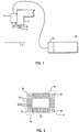
In a method for determining the presence and position of fiducials on the surface of a printed circuit substrate 6 in gray level images to sub-pixel accuracy, summation profile technique is used to decrease the amount of computation required and thereby increase throughput by enabling real time operation in a total component placement system. A robot arm 3 has an end effector 2 carrying a component 4 to be placed on a substrate 6. The substrate 6 is illuminated by a light source 10. A camera 8, carrried by the arm 3 senses the substrate 6 to obtain gray level pixel data which is transmitted through a frame grabber 22 to a vision processor 20. This latter determines, from data received, the presence or absence of a fiducial, finds the approximate centre thereof, and calculates the centre to sub-pixel accuracy.
Description
- The present invention relates to methods of locating objects and particularly to computer vision techniques for locating objects in a field of view. More specifically, but not exclusively, it relates to finding locations on a substrate at which electronic components are to be placed and in controlling other hardware in a total placement system.
- Great accuracy is required in placing electronic components on printed circuit substrates for subsequent bonding thereto. This requirement for accuracy is particularly significant when extremely fine pitch components are to be placed. It is known in the prior art to utilise computer vision techniques for such placement. However, it is conventional to perform extensive manipulation of all pixels in a camera field of view to achieve accuracy when placing surface mountable components.
- A fiducial is a piece of artwork on a printed circuit substrate whose distance from all other artwork is known. As a fiducial can be located automatically within an image by means of a vision system, the image of the fiducial space coordinates may be mapped to real world coordinates to allow automatic derivation of real world coordinates for other parts of the substrate artwork. This information is used to control a robot and other motive means for manipulating a printed circuit board and the components to be placed thereon.
- It is known to find objects within an image using gray level techniques but extensive manipulation of all pixels in the search window is traditionally necessary. Some increase in processing time may be achieved by embedding primitive operations in hardware. However, such an arrangement alters the scale of timings only, not their order. In either hardware or software the order of search is N x N, i.e. two dimensional.
- These techniques for finding fiducials as part of the process for aligning components accurately on placement sites are described in the literature. IBM Technical Disclosure Bulletin Volume 31,
Number 10, March 1989, pp. 222, discloses the use of vision techniques for calibrating a printed circuit board to a robot coordinate system using a camera and fiducials on the board as well as footprint fiducials. - IBM Technical Disclosure Bulletin
Volume 32,Number 7, December 1989, pp. 66, also discloses the use of a vision system for viewing board fiducials at the component footprint in preparation for a surface mount component placement. - IBM Technical Disclosure Bulletin
Volume 30, Number 1, June 1987, pp. 228, discloses the use of computer vision and locating board fiducials for accurate component placement. - IBM Technical Disclosure Bulletin
Volume 32, Number 8A, January 1990, pp. 5, relates to the use of vision techniques and determining fiducial mark location prior to component placement. It is desirable to use vision processing to locate fiducials with the highest possible degree of accuracy while minimising the amount of time and computational resources required. - The present invention represents an improvement over the prior art by simplifying the process for or finding fiducials. The present invention uses summation profiles to find fiducials on a printed circuit board, which leads to a great reduction in the amount of pixel data to be analysed.
- As is frequently the case, fiducials are circular in configuration and the present invention takes advantage of the symmetry of circular and convex polygonal fiducials to reduce the two-dimensional information in a search window to two one-dimensional summation profiles which, abstracted, represent the average value of pixels along rows and columns in the search window.
- A camera captures gray level images which are digitised and stored in an array of pixel values in system memory. Summation data is obtained by summing all pixels in each row and column.
- Then the edges of the fiducial in the two one-dimensional profiles are found and ordered to determine the approximate centre of the fiducial. After the approximate centre is found, a similar method of edge detection is performed on rows and columns of pixels in the neighbourhood of the approximate centre in order to determine the centre to sub-pixel accuracy.
- Thus, N x N computation is restricted to producing summation profiles which can be processed quickly as more complex processing is of the order N. Summation profiles enable the finding of the approximate centre of a fiducial and the approximate centre is used to locate a very small order subset of two dimensional data which is processed to find the centre of the fiducial to sub-pixel accuracy.
- Once the centre of a fiducial is found to sub-pixel accuracy, that information is passed in a conventional manner to downstream system controls, e.g., for guiding robotic placement of a component.
- The scope of the invention is defined by the appended claims; and how it can be carried into effect is described with reference to the accompanying drawings in which:
- Fig. 1 is the schematic diagram of a placement system in which the present invention is used;
- Fig. 2 is a plan view of a portion of the surface of a printed circuit substrate;
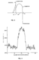
- Fig. 3 shows an idealised summation profile;
- Fig. 4 shows a summation profile;
- Fig. 5 graphically illustrates screening for finding fiducial edges;
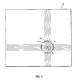
- Fig. 6 graphically illustrates finding the exact centre of a fiducial; and
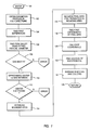
- Fig. 7 is a flowchart describing the logic performed in finding fiducial centres.
- Robot arm 3 (Fig. 1) includes an
end effector 2 carrying acomponent 4 to be placed on asubstrate 6. Acamera 8 is borne onrobot arm 3 so as to look downwardly at printedcircuit substrate 6.Camera 8 may be a 480 x 512 sensor array for obtaining gray level pixel data. Acircular light source 10 is mounted on therobot end effector 2 to illuminatesubstrate 6. Vision processor 20 includes aframe grabber 22 for accepting analog input fromcamera 8, converting the data to digital form and storing it. Whilstframe grabber 22 is shown for illustrative purposes, any apparatus for acquiring digitised gray level image data is suitable. - At a site 28 (Fig. 2) for a component on the surface of printed
circuit substrate 6, fourfiducials 30 define the position of the site and ofmetallized pads 32 on which leads of the surface mount component will be mounted. Apparatus calibration procedures include establishing the number of pixels per millimetre in both the X and Y directions. Substrate artwork specifications are also known so that predetermination of a search window forcamera 8 is facilitated. Such windows are represented generally at 36 and 38. Determination of the presence and location of the fiducials located bysearch windows - The method for such determination according to the present invention includes two phases. In the first phase, the presence/absence of a fiducial is determined and, if present, the approximate centre of the fiducial is determined. In the second phase, the location of the approximate centre of the fiducial is used in finding the centre of the fiducial to sub-pixel accuracy.
- Summation profiles of the search window are taken in the X and Y directions. High and low first differences in the profiles are deemed to correspond to the leading and trailing edges of the fiducial. Fig. 3 shows an idealised summation profile for a fiducial 30.
Leading edge 42 is found easily by taking the high first. Similarlytrailing edge 50 is found by the low first. Then thecentre point 56 is the midpoint therebetween. If the window is cluttered by objects other than the fiducial, first differences are screened to find the best match with the fiducial diameter. The presence of the fiducial is rejected if no exactly potential match for the diameter is found. - The surface mount component to be placed is a TAB device having leads with dimensions in the 40 to 12 mil range. The diameter size for a fiducial for leads in this range is typically 1.016 mn (0.040 in). The screening parameters are chosen based upon the expected contrast between the fiducial and the printed circuit board surface. However those having skill in the art will realise that other screening parameters corresponding to different printed circuit board/fiducial contrast values may be used.
- A summation profile for a typical fiducial in the Y direction is shown in Fig. 4. The corresponding summation profile in the X direction would look very much like that in Fig. 4.
- Fig. 5 shows a graph of the first differences of a summation profile similar to that in Fig. 4. The screening parameters have been selected as 1.85 sigma from the mean. Lines C and D represent the upper and lower screening levels.
- High values are those greater than 1.85 sigma from the mean. If no peaks meet this criterion, then the maximum peak is chosen. Similarly, low values are those below -1.85 sigma from the mean or the minimum value peak if it is above -1.85 sigma from the mean.
- For contiguous runs 60, 62 of high values and runs 64, 66 of low values meeting these criteria, the maxi values among highs and the minimum value among lows are chosen as shown at 70 and 72, and 74 and 76.
- All combinations of chosen high and lows whose distance apart is within one-quarter of the expected fiducial diameter as represented by
arrows high peaks low peaks - Any pairs of combinations for which both the leading and trailing edges of the two pairs are no further apart than one-quarter of the diameter of the fiducial are assumed to be the same candidate and the pair whose size is closest to the expected diameter is selected.
- If after the above screenings have been applied, exactly one candidate pair of high and low peaks is found, its approximate centre is deemed to be half way between the two peak valley pairs as shown at 88. If not exactly one candidate remains, then the fiducial is deemed absent and rejected.
- In the next phase of processing, the X, Y coordinates of the exact centre of the fiducial are found. Small arrays of pixels from
frame grabber 22 are examined. First, N rows of pixels centred at the approximate Y location are considered in order to find the X coordinate. - As shown in Fig. 6, seven rows and seven columns surrounding the
approximate centre 88 of the fiducial are considered as shown at 90. Boundingconcentric arcs - Once the pixel data is retrieved, first differences are taken by subtracting adjacent values along each row or column, then using the first differences so calculated, edges within those ranges are determined.
- The boundaries of the fiducial whose centre is halfway in between are determined. The average of the centres found in this manner is the value of the X coordinate of the centre of fiducial 30 to sub-pixel accuracy.
- In a similar manner, the Y coordinate of the exact centre is determined. First differences along each column in the bounding arcs described at points 0.75 to 1.25 times the known radius of the fiducial on both sides of the approximate Y centre are taken. Again, using first those differences enables the edges within those ranges are found.
- Refer now to Fig. 7 which is a flow chart of logic followed in vision processor 20. Logic is entered at
terminal 100 after digitised pixel data fromwindow 36 is stored. Instep 102, summation profiles in both X and Y are obtained, that is, within the area of interest, all the pixel values in rows are summed and all the pixel values in columns are summed, to yield two one-dimensional arrays. - First differences are found in
step 104, by subtracting adjacent valleys from adjacent peaks. Then, the first differences so found are screened instep 106 to yield peak-valley pairs prior to comparing the peak valley pairs with known fiducial X and Y diameters instep 108 and finding the best match. If no best match is found instep 108, an error condition is returned. Otherwise, the approximate centre is then calculated instep 110 by choosing the point halfway between the peak-valley pair chosen. - As it is necessary to find both X and Y summation profiles and to derive approximate centres therefrom, it is determined in
step 112 whether both an X centre and a Y centre have been found. If not, an error condition is returned. - When the X and Y coordinates of the approximate centre have been successfully found, the logic is ready to begin finding the X and Y coordinates of the exact centre of the fiducial to sub-pixel accuracy. In the
first step 114 in that process, two concentric bounding arcs are established, an inner bounding arc of 0.75 times the fiducial radius in the appropriate direction on either side of the approximate centre found above, and an outer bounding arc 1.25 times the fiducial radius from the approximate centre in both directions. Pixels are not square, so that the bounding arcs may not describe two concentric circles. - Up to this point all calculations have been performed on the one dimensional summation profiles due to the benefit in throughput achieved by minimising the number of calculations to be performed. While our process for finding the exact centre requires manipulation of two dimensional arrays, these are very, very small, being the pixels within the concentric bounding arcs at the four locations, as shown in Fig. 6. Thus in
step 116, those pixel arrays are retrieved from frame grabber 22 (Fig. 1). Instep 118, first differences of pixel data are found. This is followed by finding the edge coordinates within the first differences instep 120. For each row or column, a centre is calculated instep 122, and instep 124, all row centres are averaged and all column centres are averaged to provide the exact centre. The process then returns instep 126. - Two kinds of fiducials can be handled by simple profile methods. The first is a fiducial which has been shaved during the cleaning process. This causes its edge to to appear as a ramp in the image. since the entire ramp causes responses in the first derivative, the pixel which is furthermost from the centre of the fiducial and closest to the background in intensity is located as the edge of the fiducial. The second type of fiducial is unabraded, which creates a very sharp edge in its profile. Here the strongest response in the first derivative is the location of the edge.
- Differentials in etching and similar processes cause some fiducials to appear as two concentric circles resembling in the currency of the United States of America a dime stacked on a nickel. Empirically, has been discovered that the edge of the smaller inner circle produces a response in the first derivative which is approximately twice that of the outer circle. To find the edge of the fiducial, the edge of the inner circle is found first, and then first derivative responses are searched for towards the outside, until they fall below 45% of that of the inner circle.
- What follows is a Pseudo code description of our technique for finding the exact centre of a fiducial.


- While the subject invention has been described having reference to a particular preferred embodiment, various changes including those above mentioned in form and detail may be made without departing from the scope of the invention as claimed.
- Methods and apparatus for visual inspection of components prior to placement are described and claimed in EP -A- filed contemporaneously with this application and based upon US SN 07/634,675.
Claims (15)
- A method for locating a circular or symmetrical convex polygonal fiducial of known dimensions on a circuit substrate comprising the steps of: determining fiducial presence, finding approximate fiducial centre, and calculating fiducial centre to sub-pixel accuracy.
- A method according to Claim 1, wherein the determining step comprises: acquiring a two dimensional digitised image array, selecting a subarray representing a predetermined area within which a fiducial is expected, calculating summation profiles of rows and columns in the selected subarray, constructing first difference profile corresponding to each calculated summation profile, and screening the first difference profiles to choose presumptive leading and trailing edges of the fiducial.
- A method according to Claim 2, wherein the finding step comprises, taking midpoints between presumptive leading nd trailing edges.
- A method according to Claim 2 or 3, wherein the calculating step comprises, selecting from the two-dimensional digitised image array, four two-dimensional subarrays located a predetermined distance on either side of the X and Y coordinates found in the finding step, determining first differences for each of the four subarrays, choosing maximum and minimum values for X and Y from the first differences from subarrays located on either side of the X and Y values, respectively, found in the finding step, and averaging chosen values for X and Y, respectively, to find exact X and Y values.
- A method according to Claim 4 wherein the selecting step includes examining a plurality, preferably seven, rows of pixels centred about X coordinate of approximate centre, retrieving pixel data along each row from 0.75 to 1.25 times the fiducial radius distance and from -1.25 to -0.75 times the fiducial radius distance from X, examining a plurality, preferably seven, columns of pixels centred about Y coordinate of approximate centre, and retrieving pixel data along each column from 0.75 to 1.25 times the fiducial radius distance and from -1.25 to -0.75 times the fiducial radius distance from Y.
- A method according to Claim 4, 5 or 6, including the steps of examining four subarrays of pixel data selected as a function of their location in relation to established approximate X, Y centre coordinates, finding first differences in each subarray, and averaging maximum and minimum values in each subarray.
- A method according to Claim 2, 3, 4, 5 or 6, wherein the screening step includes repeatedly comparing pairs of plus and minus peaks from first differences of the summation profiles to obtain candidate peak and valley pairs separated by a distance within one fourth of expected fiducial radius dimension, and picking from the candidate peak and valley pairs, one pair whose distance apart most closely matches expected fiducial diameter dimension.
- A method of locating a fiducial centre to sub pixel accuracy, comprising the steps of finding leading and trailing edges and approximate centre coordinates through analysis of one dimensional first differences of summation profile arrays, and determining exact centre coordinates through analysis of four narrowly constrained, two dimensional pixel arrays whose locations are chosen as a function of distance from approximate centre coordinates.
- A method according to Claim 8, wherein the finding step includes, obtaining a digitised image array of whole scene, examining a predetermined two dimensional subarray wherein the fiducial is expected, and forming one-dimensional summation profiles for rows and columns of pixels in the subarray, calculating row and column summations of pixel values in the subarray for structuring a one dimensional profile array, assuming leading edge of the fiducial to correspond to a high positive derivative and trailing edge to correspond to low negative derivative in each one-dimensional profile array, and establishing approximate X, Y centre coordinates, at points midway between the high and low derivatives.
- A method accordig to Claim 8 or 9, wherein the determining step includes examining four subarrays of pixel data selected as a function of their location in relation to established approximate X, Y centre coordinates, finding first differences in each subarray, and averaging maximum and minimum values in each subarray.
- A method of precisely locating an object in a field of view, comprising the steps of obtaining a digitised image array of whole scene, examining a predetermined two dimensional subarray wherein object is expected, and forming one dimensional summation profiles for rows and columns of pixels in the subarray.
- A method according to Claim 11, wherein said forming step includes calculating row summations of pixel values in the subarray for structuring a one-dimensional profile array, and calculating column summations of pixel values in the subarray for structuring a one-dimensional profile array.
- A method according to Claim 12, including assuming leading edge of the object to correspond to a high positive derivative and trailing edge to correspond to low negative derivative in each one-dimensional profile array, and establishing approximate X, Y centre coordinates, at points midway between the high and low derivatives.
- A method according to Claim 12 or 13, wherein the calculating step comprises establishing two pairs of concentric bounding arcs about coordinates of approximate centre as a function of distance therefrom, finding first differences in pixel data within the concentric bounding arcs, and averaging maximum and minimum first difference values within concentric bounding arc pairs.
- A method according to Claim 11, 12, 13 or 14, examining four subarrays of pixel data selected as a function of their location in relation to established approximate X, Y centre coordinates, finding first differences in each subarray, and averaging maximum and minimum values in each subarray.
Applications Claiming Priority (2)
| Application Number | Priority Date | Filing Date | Title |
|---|---|---|---|
| US07/634,642 US5086478A (en) | 1990-12-27 | 1990-12-27 | Finding fiducials on printed circuit boards to sub pixel accuracy |
| US634642 | 1996-04-18 |
Publications (2)
| Publication Number | Publication Date |
|---|---|
| EP0493106A2 true EP0493106A2 (en) | 1992-07-01 |
| EP0493106A3 EP0493106A3 (en) | 1994-03-09 |
Family
ID=24544643
Family Applications (1)
| Application Number | Title | Priority Date | Filing Date |
|---|---|---|---|
| EP91312006A Ceased EP0493106A2 (en) | 1990-12-27 | 1991-12-23 | Method of locating objects |
Country Status (3)
| Country | Link |
|---|---|
| US (1) | US5086478A (en) |
| EP (1) | EP0493106A2 (en) |
| JP (1) | JPH0712520A (en) |
Families Citing this family (69)
| Publication number | Priority date | Publication date | Assignee | Title |
|---|---|---|---|---|
| US5600734A (en) * | 1991-10-04 | 1997-02-04 | Fujitsu Limited | Electron beam tester |
| USRE38559E1 (en) | 1984-12-20 | 2004-07-27 | Orbotech Ltd | Automatic visual inspection system |
| US6067379A (en) * | 1988-12-09 | 2000-05-23 | Cognex Corporation | Method and apparatus for locating patterns in an optical image |
| JP2531013B2 (en) * | 1990-11-22 | 1996-09-04 | 株式会社村田製作所 | Positioning mark detection device for cutting ceramic laminated body and positioning mark detection method for cutting |
| GB9102713D0 (en) * | 1991-02-08 | 1991-03-27 | Univ London | Centroiding method for photon counting detectors |
| CA2109943A1 (en) * | 1991-06-13 | 1992-12-23 | Herbert S. Chow | Automated specimen analyzing apparatus and method |
| US6771812B1 (en) | 1991-12-27 | 2004-08-03 | Minolta Co., Ltd. | Image processor |
| US5956420A (en) * | 1991-12-27 | 1999-09-21 | Minolta Co., Ltd. | Image processor |
| US5282254A (en) * | 1992-06-29 | 1994-01-25 | Siemens Corporate Research, Inc. | Method for locating an edge portion of an aperture in a filter member in X-ray fluoroscopy apparatus |
| JP2764224B2 (en) * | 1993-03-01 | 1998-06-11 | ユナイテツド パーセル サービス オブ アメリカ インコーポレイテツド | Method and apparatus for determining the position of a supplementary target |
| JP2710202B2 (en) * | 1993-03-24 | 1998-02-10 | インターナショナル・ビジネス・マシーンズ・コーポレイション | Method and data processor for bordering closed contour image with convex polygon |
| GB2276446B (en) * | 1993-03-26 | 1996-07-03 | Honda Motor Co Ltd | Method of measuring the position of a hole |
| JP3237975B2 (en) * | 1993-09-20 | 2001-12-10 | 富士通株式会社 | Image processing device |
| US5655030A (en) * | 1993-12-27 | 1997-08-05 | Uht Corporation | Method for detecting the center of target marks by image processing |
| US6178262B1 (en) * | 1994-03-11 | 2001-01-23 | Cognex Corporation | Circle location |
| US5602937A (en) * | 1994-06-01 | 1997-02-11 | Cognex Corporation | Methods and apparatus for machine vision high accuracy searching |
| US5638459A (en) * | 1994-09-20 | 1997-06-10 | Neopath, Inc. | Method and apparatus for detecting a microscope slide coverslip |
| US5642442A (en) * | 1995-04-10 | 1997-06-24 | United Parcel Services Of America, Inc. | Method for locating the position and orientation of a fiduciary mark |
| US5801966A (en) * | 1995-07-24 | 1998-09-01 | Cognex Corporation | Machine vision methods and articles of manufacture for determination of convex hull and convex hull angle |
| US6026176A (en) | 1995-07-25 | 2000-02-15 | Cognex Corporation | Machine vision methods and articles of manufacture for ball grid array inspection |
| US5757956A (en) * | 1995-10-31 | 1998-05-26 | Cognex Corp. | Template rotating method for locating bond pads in an image |
| US5754679A (en) * | 1995-10-31 | 1998-05-19 | Cognex Corp. | Image rotating method for locating bond pads in an image |
| US5845007A (en) * | 1996-01-02 | 1998-12-01 | Cognex Corporation | Machine vision method and apparatus for edge-based image histogram analysis |
| US5872870A (en) * | 1996-02-16 | 1999-02-16 | Cognex Corporation | Machine vision methods for identifying extrema of objects in rotated reference frames |
| GB2310716A (en) * | 1996-02-28 | 1997-09-03 | Daewoo Electronics Co Ltd | Recognition of a fiducial mark on a printed circuit board |
| US5909504A (en) * | 1996-03-15 | 1999-06-01 | Cognex Corporation | Method of testing a machine vision inspection system |
| US6259827B1 (en) | 1996-03-21 | 2001-07-10 | Cognex Corporation | Machine vision methods for enhancing the contrast between an object and its background using multiple on-axis images |
| US6298149B1 (en) | 1996-03-21 | 2001-10-02 | Cognex Corporation | Semiconductor device image inspection with contrast enhancement |
| US5949901A (en) * | 1996-03-21 | 1999-09-07 | Nichani; Sanjay | Semiconductor device image inspection utilizing image subtraction and threshold imaging |
| US5978502A (en) * | 1996-04-01 | 1999-11-02 | Cognex Corporation | Machine vision methods for determining characteristics of three-dimensional objects |
| US6137893A (en) * | 1996-10-07 | 2000-10-24 | Cognex Corporation | Machine vision calibration targets and methods of determining their location and orientation in an image |
| US5960125A (en) | 1996-11-21 | 1999-09-28 | Cognex Corporation | Nonfeedback-based machine vision method for determining a calibration relationship between a camera and a moveable object |
| US5953130A (en) * | 1997-01-06 | 1999-09-14 | Cognex Corporation | Machine vision methods and apparatus for machine vision illumination of an object |
| US5727461A (en) * | 1997-02-06 | 1998-03-17 | Amtx, Inc. | Method of forming fiducials, and stencils containing such fiducials |
| US6075881A (en) * | 1997-03-18 | 2000-06-13 | Cognex Corporation | Machine vision methods for identifying collinear sets of points from an image |
| US5974169A (en) * | 1997-03-20 | 1999-10-26 | Cognex Corporation | Machine vision methods for determining characteristics of an object using boundary points and bounding regions |
| US6141033A (en) * | 1997-05-15 | 2000-10-31 | Cognex Corporation | Bandwidth reduction of multichannel images for machine vision |
| US6608647B1 (en) | 1997-06-24 | 2003-08-19 | Cognex Corporation | Methods and apparatus for charge coupled device image acquisition with independent integration and readout |
| US5978080A (en) * | 1997-09-25 | 1999-11-02 | Cognex Corporation | Machine vision methods using feedback to determine an orientation, pixel width and pixel height of a field of view |
| US6025854A (en) * | 1997-12-31 | 2000-02-15 | Cognex Corporation | Method and apparatus for high speed image acquisition |
| US6282328B1 (en) | 1998-01-28 | 2001-08-28 | Cognex Corporation | Machine vision systems and methods for morphological transformation of an image with non-uniform offsets |
| US6236769B1 (en) | 1998-01-28 | 2001-05-22 | Cognex Corporation | Machine vision systems and methods for morphological transformation of an image with zero or other uniform offsets |
| US6381375B1 (en) | 1998-02-20 | 2002-04-30 | Cognex Corporation | Methods and apparatus for generating a projection of an image |
| US6215915B1 (en) | 1998-02-20 | 2001-04-10 | Cognex Corporation | Image processing methods and apparatus for separable, general affine transformation of an image |
| US6424734B1 (en) * | 1998-04-03 | 2002-07-23 | Cognex Corporation | Fiducial mark search using sub-models |
| US6516092B1 (en) | 1998-05-29 | 2003-02-04 | Cognex Corporation | Robust sub-model shape-finder |
| US7016539B1 (en) | 1998-07-13 | 2006-03-21 | Cognex Corporation | Method for fast, robust, multi-dimensional pattern recognition |
| US6687402B1 (en) | 1998-12-18 | 2004-02-03 | Cognex Corporation | Machine vision methods and systems for boundary feature comparison of patterns and images |
| US6381366B1 (en) | 1998-12-18 | 2002-04-30 | Cognex Corporation | Machine vision methods and system for boundary point-based comparison of patterns and images |
| US6684402B1 (en) | 1999-12-01 | 2004-01-27 | Cognex Technology And Investment Corporation | Control methods and apparatus for coupling multiple image acquisition devices to a digital data processor |
| US6748104B1 (en) | 2000-03-24 | 2004-06-08 | Cognex Corporation | Methods and apparatus for machine vision inspection using single and multiple templates or patterns |
| US7006669B1 (en) | 2000-12-31 | 2006-02-28 | Cognex Corporation | Machine vision method and apparatus for thresholding images of non-uniform materials |
| US6959112B1 (en) | 2001-06-29 | 2005-10-25 | Cognex Technology And Investment Corporation | Method for finding a pattern which may fall partially outside an image |
| US8081820B2 (en) * | 2003-07-22 | 2011-12-20 | Cognex Technology And Investment Corporation | Method for partitioning a pattern into optimized sub-patterns |
| US7190834B2 (en) * | 2003-07-22 | 2007-03-13 | Cognex Technology And Investment Corporation | Methods for finding and characterizing a deformed pattern in an image |
| EP1701231A1 (en) * | 2005-03-08 | 2006-09-13 | Mydata Automation AB | Method of calibration |
| US7639861B2 (en) | 2005-09-14 | 2009-12-29 | Cognex Technology And Investment Corporation | Method and apparatus for backlighting a wafer during alignment |
| US8111904B2 (en) * | 2005-10-07 | 2012-02-07 | Cognex Technology And Investment Corp. | Methods and apparatus for practical 3D vision system |
| US8162584B2 (en) * | 2006-08-23 | 2012-04-24 | Cognex Corporation | Method and apparatus for semiconductor wafer alignment |
| US8116550B2 (en) * | 2006-12-20 | 2012-02-14 | Cytyc Corporation | Method and system for locating and focusing on fiducial marks on specimen slides |
| US7881603B2 (en) | 2008-09-26 | 2011-02-01 | Apple Inc. | Dichroic aperture for electronic imaging device |
| US8610726B2 (en) * | 2008-09-26 | 2013-12-17 | Apple Inc. | Computer systems and methods with projected display |
| US20100079653A1 (en) * | 2008-09-26 | 2010-04-01 | Apple Inc. | Portable computing system with a secondary image output |
| US8508588B2 (en) * | 2010-05-19 | 2013-08-13 | General Electric Company | Methods and systems for identifying well wall boundaries of microplates |
| US8538132B2 (en) * | 2010-09-24 | 2013-09-17 | Apple Inc. | Component concentricity |
| US9679224B2 (en) | 2013-06-28 | 2017-06-13 | Cognex Corporation | Semi-supervised method for training multiple pattern recognition and registration tool models |
| US9356061B2 (en) | 2013-08-05 | 2016-05-31 | Apple Inc. | Image sensor with buried light shield and vertical gate |
| CN106980862B (en) * | 2017-03-17 | 2020-06-09 | 湘潭大学 | Circular image recognition feature extraction method and system |
| CN110285760A (en) * | 2019-06-27 | 2019-09-27 | 重庆矢崎仪表有限公司 | A kind of FPC assembling detection system and method |
Citations (3)
| Publication number | Priority date | Publication date | Assignee | Title |
|---|---|---|---|---|
| US4688088A (en) * | 1984-04-20 | 1987-08-18 | Canon Kabushiki Kaisha | Position detecting device and method |
| US4860374A (en) * | 1984-04-19 | 1989-08-22 | Nikon Corporation | Apparatus for detecting position of reference pattern |
| EP0358794A1 (en) * | 1988-09-14 | 1990-03-21 | Nkk Corporation | Apparatus for detecting a shape of a groove |
Family Cites Families (6)
| Publication number | Priority date | Publication date | Assignee | Title |
|---|---|---|---|---|
| JPS5369063A (en) * | 1976-12-01 | 1978-06-20 | Hitachi Ltd | Detector of position alignment patterns |
| JPS57102017A (en) * | 1980-12-17 | 1982-06-24 | Hitachi Ltd | Pattern detector |
| JPS60222860A (en) * | 1984-04-20 | 1985-11-07 | Canon Inc | Position detector |
| JPS6311804A (en) * | 1986-07-02 | 1988-01-19 | Hitachi Ltd | Mark position detection system for positioning |
| JPH0663740B2 (en) * | 1987-09-28 | 1994-08-22 | 住友重機械工業株式会社 | Alignment mark position detection method |
| JPH0228503A (en) * | 1988-07-19 | 1990-01-30 | Nippon Steel Corp | Method for recognizing circular body and detecting center position |
-
1990
- 1990-12-27 US US07/634,642 patent/US5086478A/en not_active Expired - Fee Related
-
1991
- 1991-09-13 JP JP3263293A patent/JPH0712520A/en active Pending
- 1991-12-23 EP EP91312006A patent/EP0493106A2/en not_active Ceased
Patent Citations (3)
| Publication number | Priority date | Publication date | Assignee | Title |
|---|---|---|---|---|
| US4860374A (en) * | 1984-04-19 | 1989-08-22 | Nikon Corporation | Apparatus for detecting position of reference pattern |
| US4688088A (en) * | 1984-04-20 | 1987-08-18 | Canon Kabushiki Kaisha | Position detecting device and method |
| EP0358794A1 (en) * | 1988-09-14 | 1990-03-21 | Nkk Corporation | Apparatus for detecting a shape of a groove |
Non-Patent Citations (1)
| Title |
|---|
| IBM TECHNICAL DISCLOSURE BULLETIN vol. 31, no. 10, March 1989, NY US pages 222 - 228 * |
Also Published As
| Publication number | Publication date |
|---|---|
| US5086478A (en) | 1992-02-04 |
| JPH0712520A (en) | 1995-01-17 |
| EP0493106A3 (en) | 1994-03-09 |
Similar Documents
| Publication | Publication Date | Title |
|---|---|---|
| EP0493106A2 (en) | Method of locating objects | |
| EP0107820B1 (en) | Robot vision system | |
| US5081689A (en) | Apparatus and method for extracting edges and lines | |
| US4441205A (en) | Pattern recognition system | |
| US6748104B1 (en) | Methods and apparatus for machine vision inspection using single and multiple templates or patterns | |
| JP3522280B2 (en) | Method and apparatus for a ball bond inspection system | |
| JP2773818B2 (en) | Automatic image recognition apparatus and method | |
| US5185811A (en) | Automated visual inspection of electronic component leads prior to placement | |
| JPS63163983A (en) | System for correlating outputs of laplacean and gaussian filters for quick calculation and image processing thereof | |
| EP0157299B1 (en) | Image processing apparatus | |
| EP1928578A2 (en) | An inspection system and a method for detecting defects based upon a reference frame | |
| US6075881A (en) | Machine vision methods for identifying collinear sets of points from an image | |
| US6690819B1 (en) | Method and apparatus for recognizing components | |
| JP4511942B2 (en) | POSITION DETECTION DEVICE, POSITION DETECTION METHOD, AND ELECTRONIC COMPONENT CONVEYING DEVICE | |
| EP0848245B1 (en) | Method and apparatus for measuring the height of an object | |
| US6765666B1 (en) | System and method for inspecting bumped wafers | |
| US6898333B1 (en) | Methods and apparatus for determining the orientation of an object in an image | |
| US6577758B1 (en) | Image position detection technique in which input parameters can be easily determined | |
| US6295384B1 (en) | Removing noise caused by artifacts from a digital image signal | |
| US7551762B2 (en) | Method and system for automatic vision inspection and classification of microarray slides | |
| USRE38716E1 (en) | Automatic visual inspection system | |
| US7274801B2 (en) | Automatic target recognition system with Elliptical Laplacian Pyramid filter | |
| EP0493105A2 (en) | Data processing method and apparatus | |
| JP3281946B2 (en) | 3D object recognition method | |
| KR20030005301A (en) | Method and device for processing images |
Legal Events
| Date | Code | Title | Description |
|---|---|---|---|
| PUAI | Public reference made under article 153(3) epc to a published international application that has entered the european phase |
Free format text: ORIGINAL CODE: 0009012 |
|
| AK | Designated contracting states |
Kind code of ref document: A2 Designated state(s): DE FR GB |
|
| 17P | Request for examination filed |
Effective date: 19921022 |
|
| PUAL | Search report despatched |
Free format text: ORIGINAL CODE: 0009013 |
|
| AK | Designated contracting states |
Kind code of ref document: A3 Designated state(s): DE FR GB |
|
| 17Q | First examination report despatched |
Effective date: 19950411 |
|
| STAA | Information on the status of an ep patent application or granted ep patent |
Free format text: STATUS: THE APPLICATION HAS BEEN REFUSED |
|
| 18R | Application refused |
Effective date: 19960427 |