EP0491289A1 - Double-confocal scanning microscope - Google Patents
Double-confocal scanning microscope Download PDFInfo
- Publication number
- EP0491289A1 EP0491289A1 EP91121368A EP91121368A EP0491289A1 EP 0491289 A1 EP0491289 A1 EP 0491289A1 EP 91121368 A EP91121368 A EP 91121368A EP 91121368 A EP91121368 A EP 91121368A EP 0491289 A1 EP0491289 A1 EP 0491289A1
- Authority
- EP
- European Patent Office
- Prior art keywords
- scanning microscope
- microscope according
- interference
- light
- passed
- Prior art date
- Legal status (The legal status is an assumption and is not a legal conclusion. Google has not performed a legal analysis and makes no representation as to the accuracy of the status listed.)
- Granted
Links
Images


Classifications
-
- G—PHYSICS
- G02—OPTICS
- G02B—OPTICAL ELEMENTS, SYSTEMS OR APPARATUS
- G02B21/00—Microscopes
- G02B21/0004—Microscopes specially adapted for specific applications
- G02B21/002—Scanning microscopes
- G02B21/0024—Confocal scanning microscopes (CSOMs) or confocal "macroscopes"; Accessories which are not restricted to use with CSOMs, e.g. sample holders
- G02B21/0052—Optical details of the image generation
- G02B21/0056—Optical details of the image generation based on optical coherence, e.g. phase-contrast arrangements, interference arrangements
Definitions
- the invention relates to a scanning microscope with at least one light source, at least one light detector and at least two objectives, which are located on different sides of the object plane, arranged so that they can illuminate at least one object point at the same time, with at least one objective being on different sides of the object plane.
- a scanning microscope for transmitted and incident light is known from DE-OS 3918412, which, viewed in the direction of light, has a polarization-optical beam splitter in front of and behind a beam scanning device, the rear beam splitter being switchable on and off in the beam path.
- This known scanning microscope is a microscopic construction that serves to be able to view samples both in transmitted light and in incident light. In contrast to the scanning microscope according to the invention, it is not used to improve the resolution by means of interference.
- This known scanning microscope is not suitable for producing interference in the focal area of the objective, since the polarization beam splitter leads to different polarization states in the lower and upper beam path. Light of different polarization is not capable of interference.
- the resolution in the Z direction is just as important as in the XY direction.
- the object on which the present invention is based is to propose a scanning microscope whose resolution is as large as possible.
- interference changing means are arranged such that light that has passed through one of the objectives with light that has passed through the lens arranged on the opposite side of the object plane on the object and / or is superimposed on the light detector so that interference patterns train and a targeted influencing of the interference pattern is possible.
- the interference changing means it is possible to influence the resulting interference pattern in a targeted manner, so that the interference pattern does not depend on statistical coincidences or on the arrangement of the microscope parts alone.
- constructive interference occurs at least temporarily at least one object point to be imaged and / or at least one light detector.
- Two lenses which are arranged on different sides of the object plane, are preferably directed towards one another and centered on the optical axis and on one another.
- At least one aperture is located in at least one plane that is optically conjugated to the object plane.
- This aperture is usually a pinhole.
- a diaphragm is provided in particular when the plane optically conjugate to the object plane is in front of a light detector that registers the light that has passed through the diaphragm and / or that this diaphragm serves as a light source.
- the interference changing means is a compensation device which overlays the object more coherently or partially coherently Wave trains made possible, each of which has been wholly or partially kicked by different lenses.
- This compensation device in particular causes constructive interference of the above-mentioned wave trains at least temporarily at least one object point to be imaged and / or at least one light detector.
- a compensation device is to be understood as a device which serves to change the path difference between wave trains which have passed or have passed through different objectives.
- At least one compensation device preferably has an at least partially transparent plate as a path-changing element, which plate has different optical thicknesses and is moved such that different optically thick parts of the plate are brought into the beam path in a time sequence.
- At least one compensation device is a mechanical translation device, which is attached to at least one optically active part and lengthens or shortens the optical path.
- a mechanical translation device is, for example, a piezoelectric or an electromechanically operated translator.
- the optically active part can in particular be a mirror, a beam or color splitter or another deflecting element.
- the interference changing means preferably bring about a translational movement of the objectives, so that the translational movement has a non-vanishing component in the direction of propagation of the wavefront, the objectives and the sample moving together along the optical axis.
- Interference changing means of different types can be present in one and the same structure.
- the interference changing means change the interference pattern quickly or slowly.
- the compensation device changes the path difference between the wave trains which have passed or have passed through the one lens and the wave trains which have passed or have passed through the other lens, either quickly or slowly.
- the lenses can also be translated either quickly or slowly.
- the change in the interference pattern is carried out periodically, the compensation device changes the path difference between the wave trains which have passed or have passed through one lens and the wave trains which have passed or have passed through the other object, periodically, or the lenses perform a periodic movement.
- At least one interference changing means with the control and / or regulating electronics the grid and / or with the image recording electronics in their function and / or tuned.
- the signal is further processed with the aid of sample electronics (lock-in, box car integrator or the like) and the sample clock is obtained with the aid of an interferometric structure with at least one light detector, or the sample Clock is independent of the optical structure, or the sample clock is obtained from signals which control or regulate the interference changing means.
- control or regulating signals include, in particular, the control or regulating signals of mechanical actuators, which are attached to optically active parts, and those of compensation devices.
- Photomultipliers are well suited as light detectors, but so are TV cameras and other receivers that convert light signals into electrical signals.
- the light source 1 (laser or short arc lamp) illuminates the pinhole 2.
- the lens 14 and behind this pinhole 2 the lens 3 is preferably arranged at a distance of their focal lengths from the pinhole.
- the wave front that passes the beam splitter cube 10 is split and deflected by the beam splitter 4 into at least two partial wave fronts that are coherent with one another.
- the term wavefront is also intended to include an entire wave train, ie also several wave fronts.
- the individual wavefront is here, as in the following, as an explanatory example for all wavefronts of a wave train.
- the part of the wavefront split off downward according to FIG. 1 hits the mirror 6 and is directed onto the objective 8 by this mirror 6.
- the part of the wavefront which is split upward according to FIG. 1 is directed onto the mirror 5 which is preferably arranged symmetrically with respect to the mirror 6.
- This mirror 5 now in turn directs the part of the wavefront that strikes it onto the objective 7.
- the two objectives 7 and 8 of the microscope are arranged directed towards one another, preferably centered on each other and on the common optical axis.
- the two objectives 7 and 8 focus the partial wave fronts hitting them in the object plane 9.
- the object to be examined is located in the object plane 9, so that the common location point on which the partial wave fronts are focused - generally the common focal point - the location point to be imaged is.
- the light emitted or reflected from there is detected by the objectives 7 and 8 and fed to the beam splitter cube 10 via the mirrors 5 and 6 and the beam splitter 4.
- This beam splitter cube 10 in turn directs the light or a part thereof via the lens 11, which is preferably arranged symmetrically to the lens 3, into the pinhole 12.
- the light detector 13 (detector) measures the intensity of the light reaching it through the pinhole 12.
- the compensation device 15 is arranged, which serves to change the optical path difference between the upper and lower partial wave fronts of the illumination or detection.
- the spatial coherence of the lighting is ensured at least by the pinhole 2.
- the partial illumination wavefront from above and the partial illumination wavefront from below are capable of interference because they originate from the common light source 1.
- they interfere with a point mapping function (PSF) H (x, y, z), which is spatially much more limited than the PSF h (x, y, z) in a conventional (confocal) microscope.
- PSF point mapping function
- the first intensity minimum of H (x, y, z) along the optical axis lies approximately half a wavelength, typically 250 nm, from the absolute intensity maximum at the focal point. At h (x, y, z), however, the first intensity minimum is more than 1000 nm away from the absolute intensity maximum.
- the detection wavefront consists of a partial wavefront above and a partial wavefront below. The partial wave fronts are focused in the point detector, where they interfere and (for reasons of symmetry) effect an image according to the point mapping function H (x, y, z) analogously to the illumination.
- the square PSF H2 (x, y, z) is responsible for the resolution.
- the squaring weakens the secondary maxima that result from the interference of the upper and lower wavefronts.
- the improved resolution in the direction of the optical axis also improves the effective lateral resolution, since the separation of the Z coordinates enables the resolution of lateral characteristics that would otherwise be overlaid by the lateral characteristics of the planes above or below. Since the scanning microscope shows the imaging point by point an improvement in resolution in the direction of the optical axis is equivalent to an improvement in the lateral direction.
- the double confocal microscope according to the invention has the highest resolution that a far field light microscope can have.
- the beam splitter cube 10 is a color beam splitter which allows the shorter-wave, exciting light to pass and which deflects the longer-wave to the side into the light detector 13.
- a beam deflection device can be arranged between the beam splitter cube 10 and the beam splitter 4.
- the beam splitter 4 which is designed as a mirror in the illustration, can be replaced by other beam splitters (cubes, etc.).
- An improvement in resolution compared to the conventional confocal microscope is also achieved if only the interference between the upper and lower detection partial wavefront, or if only the interference between the upper and lower illumination wavefront takes place.
- one of the illumination or detection beam paths in the wave fronts deflected upwards or downwards by the beam splitter 4 can be switched off with the aid of color filters. This is at the expense of the dissolution; however, this is larger than that of the conventional confocal microscope.
- the compensation device 15 which is, for example, an optical delay plate, is installed for optimal coordination of the interference, in particular in such a way that constructive interference arises. It can either be installed in the upper part of the wave front or as shown in the lower part of the wave front. It is used in particular to enable such coordination of the interference, the delay of which can be changed quickly. These can be fed back with the image recording electronics and / or the electronics for controlling and regulating the screening.
- the object is on a - not shown here - scan table, which allows the translation of the object in the X, Y and Z directions if possible. If beam scanning is carried out, a suitable scan table preferably moves along the optical axis (Z axis).
- FIG. 2 shows the schematic representation of a further embodiment of a scanning microscope which is particularly suitable for fluorescence microscopy, the parts which are identical to the parts shown in FIG. 1 being provided with the same reference symbols.
- the light from the light source 1 passes through the beam splitter 10 to the (geometric) beam splitter 4, which splits the wavefront into two components that are capable of interference. Part of it is deflected into the upper objective 7 of the microscope steered (upper illumination wavefront), the other via deflection elements in the lower objective 8 of the microscope (lower illumination wavefront). Both illumination wave fronts interfere in the common object plane 9.
- the light emanating from there is collected in a corresponding proportion by the objectives 7 and 8.
- the light collected by the objective 7 (upper detection wavefront) and likewise the light collected by the objective 8 (lower detection wavefront) reach the beam splitter 4 via deflection elements, which combines the two detection wavefronts.
- the detection wave fronts reach the pinhole 12 via the beam splitter 10.
- the light intensity through the pinhole 12 is measured by a light detector 13 and serves as a signal, that is to say as a characteristic of the object point to be imaged.
- interference of the upper or lower detection or illumination wave fronts takes place in at least one of the planes conjugated to the object plane 9 or in the object plane 9 itself.
- the compensation device 27 and 28 for changing the path difference between the upper and lower wave fronts is provided in the beam path between the beam splitter 4 and the objective 7. It is also possible that this compensation device in Beam path between the beam splitter 4 and the lens 8 is arranged.
- the compensation can optionally also be carried out by moving certain components, in particular the deflection elements described below.
- the compensation device or the optical paths are dimensioned such that there is in any case a high degree of coherence between the upper and lower wave fronts, so that the interference can take place in any case.
- the diameter of the beam in this embodiment is optionally enlarged or reduced in diameter with the aid of the components 60 and 60 ', which are arranged between the beam splitter cube 10 and the beam splitter 4. Furthermore, it passes the beam deflection unit 50. As already described above, the wave front striking the beam splitter 4 is divided into an upper and a lower illumination wave front.
- the beam splitter cube 10 is a color splitter cube which directs the light to be detected into the light detector and directs the illuminating light to the beam splitter. At least one color splitter is attached between the beam splitter 4 and the objective 7 and / or the beam splitter 4 and the microscope objective 8. According to FIG. 2, it is the two color dividers 20 and 21 that separate the detection wavefront from the illumination wavefront. Each of these passes separately through a compensation device 27 or 28, so that the illumination and the detection wavefront are separated can be changed in phase and / or amplitude.
- the compensation device 27 serves to compensate for the illumination wavefront and the compensation device 28 for the detection wavefront. Compensation means the change in the path difference between the partial wave fronts and / or the change in the phase of a wave front.
- the color dividers 22 and 23 are arranged in the lower beam path. These color dividers 22 and 23 are constructed analogously to the upper beam path. They can preferably be removed from the beam path and / or replaced by color dividers with other physical properties. Additional color dividers or pairs of color dividers can be installed between the beam splitter 4 and the lens 7 analogously to the color dividers 20 and 21, as well as between the beam splitter 4 and the lens 8, e.g. B. with multiple fluorescence, in order to be able to specifically change wave fronts with a further wavelength in the path difference of the partial wave fronts.
- the upper illumination wavefront reaches the compensation device 27 via the deflecting element 5 ′, which changes the optical path length or the phase of the wavefront. Arrives via the deflection element 5 the upper illumination wavefront into the lens 7, which focuses the light into the object plane 9. Via the deflection element 6 'and the deflection element 6, the lower illumination wavefront enters the lens 8, which likewise focuses the light into the common focal point. At the focal point, the two lighting wave fronts can interfere with one another.
- the object is preferably located on a table device which permits movement of the object in the Z direction, preferably in all three spatial directions.
- the light emanating from the object point arrives in the objectives 7 and 8, which form the upper and lower detection wavefront.
- the term "wavefront" is intended to generally include other wavefronts of the same wave train.
- the upper detection wavefront reaches the beam splitter 4 via the color splitter 21, the compensation device 28 and the color splitter 20, just as the lower detection wavefront reaches the beam splitter 4 via the color dividers 23 and 22.
- the detection wave fronts pass the color dividers and are directed onto the beam splitter 4 via the deflection elements 5 and 5 'or 6 and 6'.
- the beam splitter 4 merges the two detection wave fronts into one.
- the detection wave front reaches the lens 11 via the beam splitter 10.
- the detection wave front is converted into a spherical wave front converging in the pinhole 12 transformed.
- the two detection wavefronts interfere with one another in the plane of the pinhole 12 and form the object point of the object plane 9 in the plane of the pinhole 12 with an enlarged aperture in the sense of the double-confocal microscope.
- the arrangement is in the sense of the invention if interference of the illumination or detection partial wave fronts takes place on the object and / or on the light detector. It is therefore possible to omit a detection wavefront or an illumination wavefront.
- either the upper or the lower illumination wavefront is interrupted. This is done with the help of an opaque obstacle 45 or 46 in the upper or lower illumination wavefront. With the help of an opaque obstacle 47 or 48 in the upper or lower detection wavefront, the upper or lower detection wavefront is stopped. This enables one-sided detection and illumination with interfering illumination wave fronts.
- the beam deflection unit is designed such that the beam performs an angular movement with respect to the optical axis, the centers of the entrance pupils 7 'and 8' of the objectives preferably being 7 and 8 pivot points. Coordinated deflection units can also be inserted between the beam splitter 4 and the lens 7 or between the beam splitter 4 and the lens 8.
- the change in the relative path difference of the upper and lower wavefronts can also be done by rapidly changing the dimensions of the upper and lower beam paths, e.g. B. via a simultaneous movement of deflection units 5 and 5 'or the pairs of color dividers 20 and 21 in the direction of the optical axis. This movement can e.g. B. with the help of piezoelectric or electromechanical actuators.
- the frequency of the change in the path difference by the compensation device can be detected with the aid of an interferometric arrangement.
- the signal can be used as a clock for the sample electronics (lock-in, boxcar integrator).
- FIG. 3 shows the schematic representation of the beam path of a further embodiment of a scanning microscope, the parts which correspond to the parts shown in FIGS. 1 and 2 being provided with the same reference symbols. In the following, only those parts of the beam path that differ from the beam paths described so far are to be explained in more detail in accordance with FIG.
- a beam deflection unit is arranged between the beam splitter 10 and the beam splitter 4.
- the wave front coming from the light source 1 via the pinhole 2 and the lens 3 through the beam splitter 10 arrives at the mirror 51, which performs rapid tilting movements about an axis (eg perpendicular to the reflection plane).
- the mirror is on attached to the axis of a moving coil galvanometer, which is operated with the aid of a sinusoidal voltage.
- the lenses 52 and 53 are arranged so that the mirror 51 is imaged in the mirror 54.
- the mirror 54 performs a tilting movement that is arranged perpendicular to that of the mirror 51.
- the lenses 55 and 56 form the mirror 54 and thus also the mirror 51 in the entrance pupils 7 'and 8' of the objectives 7 and 8.
- the beam rotates in the entrance pupils 7 'and 8' in two mutually perpendicular directions.
- the fulcrums are located in the entrance pupils 7 'and 8'.
- the entrance pupils 7 'and 8', the mirror 54 and 51 are located in optically conjugate planes.
- the movements of the mirrors 51 and 54 are converted into two mutually perpendicular linear movements by the two objectives 7 and 8 of the microscope in the object plane 9. In this way, the object can be scanned in terms of area. If you attach one of the two mirrors on a biaxial mechanism, e.g. B. if you put one galvanometer mirror on top of the other, you can do without a mirror and two lenses. This is good for the yield of the detected light.
- a mirror can also be dispensed with if a deflection direction is replaced by an equivalent table movement in the object plane 9.
- At least one compensation device 27 or 28 is provided in the beam path between the beam splitter 4 and the objective 8 for changing the path difference between the upper and lower wave fronts.
- the compensation can optionally also be carried out by moving certain components, in particular the deflection elements 25 and 26.
- the compensation device or the optical paths are dimensioned such that there is a high degree of coherence between the upper and lower wavefronts, so that interference can take place.
- the further compensation device 29 is arranged in the beam path between the beam splitter 4 and the lens 7.
- the illuminating wavefront consists of parts and are incident from opposite directions of the optical axis and interfere with one another, or the detection wavefront consists of parts that initially in opposite directions move away from the object along the optical axis and interfere with each other in the light detector, or that both apply at the same time.
- the beam path of a further embodiment of a scanning microscope is shown schematically in FIG.
- This arrangement differs from the previously described embodiments of a scanning microscope in that the wave front is split into an upper and a lower illumination wave front in front of the pinhole. For this reason, there are two perforated diaphragms 102 and 202, which are responsible for the upper and lower wavefront, respectively.
- the detection wave fronts are also brought together only after passing through the apertures 102 and 202. As before, the illumination wave fronts interfere in the object, the detection wave fronts in the detector 13.
- the displacement of the pinhole 102 is preferably carried out together with the lens 101 and / or the mirror 5; the displacement of the pinhole 202 is carried out analogously together with the lens 201 and / or the mirror 6. Moving the pinhole 102 and 202 causes a targeted change in the interference pattern and thus a slightly different type of imaging.
- all beam splitters can also be a geometric (e.g. angular mirror) or physical wavefront splitter (e.g. Beam splitter cubes), or consist of several, possibly independently optically effective parts.
- the beam splitter 110 and / or 210 can be a color splitter.
- the beam splitter 4 serves to split the wave front coming from the laser into an upper and a lower illumination wave front.
- the prism 4 ' serves to deflect the lower illumination wavefront towards the deflection element 6'. From there, it reaches the lens 201 via the deflection element 6 and the beam splitter cube 210.
- the upper illumination wave front reaches the lens 101 via the compensation device 27, via the deflection elements 5 ′ and 5 and then via the beam splitter cube 110.
- the upper detection wave front reaches the lens aperture 102 and the lens 101 to the beam splitter 110, from where it reaches the compensation device 28 via the deflection elements 105 (eg mirror or prism), and from there to the beam splitter 304, where it is combined with the lower detection wavefront.
- the lower detection wavefront reaches the beam splitter 304 via the beam splitter 210 and the deflection element 206.
- the combined wavefront reaches the pinhole 12 via the lens 11.
- the beam splitter 4 can be both a physical and a geometric beam splitter, or can be composed of several optically active parts. This also applies to the beam splitter 304, which can also be replaced by a combination as is formed from 4 and 4 '.
Abstract
Description
Die Erfindung betrifft ein Rastermikroskop mit mindestens einer Lichtquelle, mindestens einem Lichtdetektor und mindestens zwei Objektiven, die auf verschiedenen Seiten der Objektebene liegen, so angeordnet, daß sie mindestens einen Objektpunkt gleichzeitig beleuchten können, wobei sich auf verschiedenen Seiten der Objektebene mindestens ein Objektiv befindet.The invention relates to a scanning microscope with at least one light source, at least one light detector and at least two objectives, which are located on different sides of the object plane, arranged so that they can illuminate at least one object point at the same time, with at least one objective being on different sides of the object plane.
Aus der DE-OS 3918412 ist ein Rastermikroskop für Durch- und Auflicht bekannt, das, in Lichtrichtung gesehen, vor und hinter einer Strahlscanningeinrichtung je einen polarisationsoptischen Strahlenteiler besitzt, wobei der hintere Strahlenteiler in den Strahlengang ein- und ausschaltbar ist. Dieses bekannte Rastermikroskop ist ein mikroskopischer Aufbau, der dazu dient, Proben sowohl im Durchlicht als auch im Auflicht betrachten zu können. Es dient im Gegensatz zu dem erfindungsgemäßen Rastermikroskop nicht zur Verbesserung der Auflösung mittels Interferenz.A scanning microscope for transmitted and incident light is known from DE-OS 3918412, which, viewed in the direction of light, has a polarization-optical beam splitter in front of and behind a beam scanning device, the rear beam splitter being switchable on and off in the beam path. This known scanning microscope is a microscopic construction that serves to be able to view samples both in transmitted light and in incident light. In contrast to the scanning microscope according to the invention, it is not used to improve the resolution by means of interference.
Dieses bekannte Rastermikroskop ist nicht dazu geeignet, Interferenz im Fokalbereich der Objektive herzustellen, da der Polarisationsstrahlteiler zu unterschiedlichen Polarisationszuständen im unteren und oberen Strahlengang führt. Licht unterschiedlicher Polarisation ist nicht interferenzfähig.This known scanning microscope is not suitable for producing interference in the focal area of the objective, since the polarization beam splitter leads to different polarization states in the lower and upper beam path. Light of different polarization is not capable of interference.
In der bisherigen Mikroskopentwicklung wurde besonderen Wert auf die Vergrößerung der Apertur der Mikroskopobjektive gelegt. Damit konnte man die Auflösung in XY-Richtung erhöhen. Bei einer Apertur von NA = 0,95 für Trockenobjektive (Aperturwinkel von 71°) scheint zunächst eine technische Grenze erreicht zu sein.In previous microscope development, special emphasis was placed on enlarging the aperture of the microscope objectives. This allowed the resolution in the XY direction to be increased. With an aperture of NA = 0.95 for dry lenses (aperture angle of 71 °), a technical limit appears to have been reached at first.
Dies gilt nicht für die Auflösung in Z-Richtung. Für die genaue dreidimensionale Erfassung eines Punktes transparenter oder fluoreszierender Objekte ist aber die Auflösung in Z-Richtung genauso wichtig wie in XY-Richtung.This does not apply to the resolution in the Z direction. For the precise three-dimensional detection of a point of transparent or fluorescent objects, the resolution in the Z direction is just as important as in the XY direction.
Die der vorliegenden Erfindung zugrundeliegende Aufgabe besteht darin, ein Rastermikroskop vorzuschlagen, dessen Auflösung möglichst groß ist.The object on which the present invention is based is to propose a scanning microscope whose resolution is as large as possible.
Diese Aufgabe wird erfindungsgemäß dadurch gelöst, daß bei einem Rastermikroskop der eingangs genannten Art Interferenzveränderungsmittel derart angeordnet sind, daß Licht, das durch eines der Objektive hindurchgegangen ist, mit Licht, das durch das auf der gegenüberliegenden Seite der Objektebene angeordnete Objektiv hindurchgegangen ist, am Objekt und/oder am Lichtdetektor so überlagert wird, daß sich Interferenzmuster ausbilden und eine gezielte Beeinflussung der Interferenzmuster möglich ist.This object is achieved in that in a scanning microscope of the type mentioned interference changing means are arranged such that light that has passed through one of the objectives with light that has passed through the lens arranged on the opposite side of the object plane on the object and / or is superimposed on the light detector so that interference patterns train and a targeted influencing of the interference pattern is possible.
Mit den Interferenzveränderungsmitteln ist es möglich, das entstehende Interferenzmuster gezielt zu beeinflussen, so daß das Interferenzmuster nicht von statistischen Zufällen oder von der Anordnung der Mikroskopteile alleine abhängt.With the interference changing means, it is possible to influence the resulting interference pattern in a targeted manner, so that the interference pattern does not depend on statistical coincidences or on the arrangement of the microscope parts alone.
Vorteilhafterweise tritt an mindestens einem abzubildenden Objektpunkt und/oder an mindestens einem Lichtdetektor zumindest zeitweise konstruktive Interferenz auf.Advantageously, constructive interference occurs at least temporarily at least one object point to be imaged and / or at least one light detector.
Vorzugsweise sind zwei Objektive, die auf verschiedenen Seiten der Objektebene angeordnet sind, gegeneinander gerichtet und zur optischen Achse und zueinander zentriert.Two lenses, which are arranged on different sides of the object plane, are preferably directed towards one another and centered on the optical axis and on one another.
Gemäß einer besonders bevorzugten Ausführungsform befindet sich in mindestens einer Ebene, die zur Objektebene optisch konjugiert ist, mindestens eine Blende. Diese Blende ist üblicherweise eine Lochblende. Eine Blende wird insbesondere dann vorgesehen, wenn sich die optisch zur Objektebene konjugierte Ebene vor einem Lichtdetektor befindet, der das durch die Blende gegangene Licht registriert und/oder daß diese Blende als Lichtquelle dient.According to a particularly preferred embodiment, at least one aperture is located in at least one plane that is optically conjugated to the object plane. This aperture is usually a pinhole. A diaphragm is provided in particular when the plane optically conjugate to the object plane is in front of a light detector that registers the light that has passed through the diaphragm and / or that this diaphragm serves as a light source.
Gemäß einer weiteren, besonders bevorzugten Ausführungsform, ist das Interferenzveränderungsmittel eine Kompensationsvorrichtung, die am Objekt eine Überlagerung kohärenter oder teilkohärenter Wellenzüge ermöglicht, die jeweils durch verschiedene Objektive ganz oder teilweise getreten sind. Diese Kompensationsvorrichtung ruft insbesondere an mindestens einem abzubildenden Objektpunkt und/oder an mindestens einem Lichtdetektor zumindest zeitweise konstruktive Interferenz der oben genannten Wellenzüge hervor. Unter einer Kompensationsvorrichtung soll eine Vorrichtung verstanden werden, die dazu dient, den Gangunterschied zwischen Wellenzügen, die durch verschiedene Objektive hindurchtreten oder hindurchgetreten sind, zu verändern.According to a further, particularly preferred embodiment, the interference changing means is a compensation device which overlays the object more coherently or partially coherently Wave trains made possible, each of which has been wholly or partially kicked by different lenses. This compensation device in particular causes constructive interference of the above-mentioned wave trains at least temporarily at least one object point to be imaged and / or at least one light detector. A compensation device is to be understood as a device which serves to change the path difference between wave trains which have passed or have passed through different objectives.
Vorzugsweise besitzt mindestens eine Kompensationsvorrichtung als gangunterschiedveränderndes Element eine zumindest teilweise transparente Platte, die unterschiedliche optische Dicken aufweist und so bewegt wird, daß in einer zeitlichen Abfolge unterschiedliche optisch dicke Teile der Platte in den Strahlengang gebracht werden.At least one compensation device preferably has an at least partially transparent plate as a path-changing element, which plate has different optical thicknesses and is moved such that different optically thick parts of the plate are brought into the beam path in a time sequence.
Gemäß einer weiteren besonders bevorzugten Ausführungsform ist mindestens eine Kompensationsvorrichtung eine mechanische Translationsvorrichtung, die an mindestens einem optisch wirksamen Teil angebracht ist und den optischen weg verlängert oder verkürzt. Eine mechanische Translationsvorrichtung ist beispielsweise ein piezoelektrisch oder ein elektromechanisch betriebener Translator. Das optisch wirksame Teil kann insbesondere ein Spiegel, ein Strahl- oder Farbteiler oder ein sonstiges Umlenkelement sein.According to a further particularly preferred embodiment, at least one compensation device is a mechanical translation device, which is attached to at least one optically active part and lengthens or shortens the optical path. A mechanical translation device is, for example, a piezoelectric or an electromechanically operated translator. The optically active part can in particular be a mirror, a beam or color splitter or another deflecting element.
In einer anderen Ausführungsform bewirken die Interferenzveränderungsmittel vorzugsweise eine Translationsbewegung der Objektive, so daß die Translationsbewegung eine nicht verschwindende Komponente in Ausbreitungsrichtung der Wellenfront besitzt, wobei sich die Objektive und die Probe zusammen entlang der optischen Achse bewegen. Interferenzveränderungsmittel verschiedener Bauart können in ein und demselben Aufbau vorhanden sein.In another embodiment, the interference changing means preferably bring about a translational movement of the objectives, so that the translational movement has a non-vanishing component in the direction of propagation of the wavefront, the objectives and the sample moving together along the optical axis. Interference changing means of different types can be present in one and the same structure.
Vorteilhafterweise verändern die Interferenzveränderungsmittel die Interferenzmuster schnell oder auch langsam. Insbesondere verändert die Kompensationsvorrichtung den Gangunterschied zwischen den Wellenzügen, die durch das eine Objektiv hindurchgehen oder hindurchgegangen sind und den Wellenzügen, die durch das andere Objektiv hindurchgehen oder hindurchgegangen sind, schnell oder auch langsam. Die Translation der Objektive kann ebenfalls entweder schnell oder auch langsam erfolgen.Advantageously, the interference changing means change the interference pattern quickly or slowly. In particular, the compensation device changes the path difference between the wave trains which have passed or have passed through the one lens and the wave trains which have passed or have passed through the other lens, either quickly or slowly. The lenses can also be translated either quickly or slowly.
Gemäß einer weiteren besonders bevorzugten Ausführungsform wird die Veränderung der Interferenzmuster periodisch durchgeführt, verändert die Kompensationsvorrichtung den Gangunterschied zwischen den Wellenzügen, die durch das eine Objektiv hindurchgehen oder hindurchgegangen sind, und den Wellenzügen, die durch das andere Objekt hindurchgehen oder hindurchgegangen sind, periodisch, oder die Objektive führen eine periodische Bewegung durch.According to a further particularly preferred embodiment, the change in the interference pattern is carried out periodically, the compensation device changes the path difference between the wave trains which have passed or have passed through one lens and the wave trains which have passed or have passed through the other object, periodically, or the lenses perform a periodic movement.
Vorzugsweise ist mindestens ein Interferenzveränderungsmittel mit der Steuer- und/oder Regelelektronik der Rasterung und/oder mit der Bildaufnahmeelektronik in ihrer Funktion rückgekoppelt und/oder abgestimmt.There is preferably at least one interference changing means with the control and / or regulating electronics the grid and / or with the image recording electronics in their function and / or tuned.
Gemäß einer weiteren besonders bevorzugten Ausführungsform wird das Signal mit Hilfe einer Sample-Elektronik (Lock-In, Boxcar-Integrator o. ä.) weiterverarbeitet und der Sample-Takt wird mit Hilfe eines interferometrischen Aufbaus mit mindestens einem Lichtdetektor gewonnen, oder der Sample-Takt ist vom optischen Aufbau unabhängig, oder der Sample-Takt wird von Signalen bezogen, welche die Interferenzveränderungsmittel steuern oder regeln. Zu diesen Steuer- oder Regelsignalen gehören insbesondere die Steuer- oder Regelsignale mechanischer Stellglieder, die an optisch wirksamen Teilen angebracht sind, und die von Kompensationsvorrichtungen.According to a further particularly preferred embodiment, the signal is further processed with the aid of sample electronics (lock-in, box car integrator or the like) and the sample clock is obtained with the aid of an interferometric structure with at least one light detector, or the sample Clock is independent of the optical structure, or the sample clock is obtained from signals which control or regulate the interference changing means. These control or regulating signals include, in particular, the control or regulating signals of mechanical actuators, which are attached to optically active parts, and those of compensation devices.
Als Lichtdetektoren sind Photomultiplier gut geeignet, aber auch TV-Kameras und auch andere Empfänger, die Lichtsignale in elektrische Signale umwandeln.Photomultipliers are well suited as light detectors, but so are TV cameras and other receivers that convert light signals into electrical signals.
Weitere besonders bevorzugte Ausführungsformen werden in den weiteren Unteransprüchen beschrieben.Further particularly preferred embodiments are described in the further subclaims.
Die Erfindung wird nun anhand der beigefügten Zeichnungen näher erläutert.The invention will now be explained in more detail with reference to the accompanying drawings.
Es zeigen:
Figur 1 die schematische Darstellung des Strahlenganges eines Rastermikroskops,Figur 2 die schematische Darstellung des Strahlenganges einer weiteren Ausführungsform eines Rastermikroskops,Figur 3 die schematische Darstellung des Strahlenganges einer anderen Ausführungsform eines Rastermikroskops undFigur 4 die schematische Darstellung des Strahlenganges einer weiteren Ausführungsform eines Rastermikroskops.
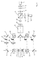
- FIG. 1 shows the schematic representation of the beam path of a scanning microscope,
- FIG. 2 shows the schematic representation of the beam path of a further embodiment of a scanning microscope,
- Figure 3 is a schematic representation of the beam path of another embodiment of a scanning microscope and
- Figure 4 is a schematic representation of the beam path of a further embodiment of a scanning microscope.
Wie in Figur 1 dargestellt, beleuchtet die Lichtquelle 1 (Laser oder Kurzbogenlampe) die Lochblende 2. Vor dieser Lochblende 2 ist die Linse 14 und hinter dieser Lochblende 2 die Linse 3 vorzugsweise im Abstand ihrer Brennweiten zur Lochblende angeordnet. Die Wellenfront, die den Strahlteilerwürfel 10 passiert, wird von dem Strahlenteiler 4 in mindestens zwei zueinander kohärente Teilwellenfronten gespalten und abgelenkt. Unter den Begriff Wellenfront soll auch ein ganzer Wellenzug fallen, d. h. auch mehrere Wellenfronten. Die einzelne Wellenfront steht hier, wie im folgenden als ein erklärendes Beispiel für alle Wellenfronten eines Wellenzuges. Der gemäß Figur 1 nach unten abgespaltete Teil der Wellenfront trifft auf den Spiegel 6 und wird von diesem Spiegel 6 auf das Objektiv 8 gelenkt. Der gemäß Figur 1 nach oben aufgespaltete Teil der Wellenfront wird auf den vorzugsweise symmetrisch zu dem Spiegel 6 angeordneten Spiegel 5 gelenkt. Dieser Spiegel 5 lenkt nunmehr seinerseits den auf ihn auftreffenden Teil der Wellenfront auf das Objektiv 7. Die beiden Objektive 7 und 8 des Mikroskops sind gegeneinander gerichtet angeordnet, vorzugsweise zueinander und zur gemeinsamen optischen Achse zentriert. Die beiden Objektive 7 und 8 fokussieren die auf sie auftreffenden Teilwellenfronten in die Objektebene 9. In der Objektebene 9 befindet sich das zu untersuchende Objekt, so daß der gemeinsame Ortspunkt, auf den die Teilwellenfronten fokussiert werden - im allgemeinen der gemeinsame Brennpunkt - der abzubildende Ortspunkt ist. Das von dort emittierte oder reflektierte Licht wird von den Objektiven 7 und 8 erfaßt und über die Spiegel 5 und 6 und den Strahlenteiler 4 dem Strahlteilerwürfel 10 zugeführt. Dieser Strahlteilerwürfel 10 lenkt nun seinerseits das Licht oder einen Teil davon über die vorzugsweise symmetrisch zu der Linse 3 angeordneten Linse 11 in die Lochblende 12. Der Lichtdetektor 13 (Detektor) mißt die Intensität des durch die Lochblende 12 zu ihm gelangenden Lichts.As shown in Figure 1, the light source 1 (laser or short arc lamp) illuminates the
Im Strahlengang zwischen dem Strahlteiler 4 und dem Spiegel 5 ist die Kompensationsvorrichtung 15 angeordnet, die zur Veränderung des optischen Gangunterschieds zwischen den oberen und unteren Teilwellenfronten der Beleuchtung oder Detektion dient.In the beam path between the
Die räumliche Kohärenz der Beleuchtung ist zumindest durch die Lochblende 2 gewährleistet. Darüberhinaus sind die Beleuchtungsteilwellenfront von oben und die Beleuchtungsteilwellenfront von unten interferenzfähig, weil sie aus der gemeinsamen Lichtquelle 1 hervorgehen. Im Fokalbereich interferieren sie zu einer Punktabbildungsfunktion (PSF) H(x,y,z), die räumlich viel stärker begrenzt ist, als die PSF h(x,y,z) in einem herkömmlichen (konfokalen) Mikroskop. Ist der Gangunterschied zwischen den beiden Beleuchtungswellenfronten gleich null, so ist das Volumen des Hauptmaximums von H(x,y,z) rund 4 mal kleiner als das Volumen des Hauptmaximums von h(x,y,z). Dies bedeutet, daß die wellenoptische Grenze der Auflösung deutlich heruntergesetzt wird. Das erste Intensitätsminimum von H(x,y,z) entlang der optischen Achse liegt etwa eine halbe Wellenlänge, typisch 250 nm, vom absoluten Intensitätsmaximum im Fokuspunkt entfernt. Bei h(x,y,z) hingegen liegt das erste Intensitätsminimum mehr als 1000 nm vom absoluten Intensitätsmaximum entfernt. Analog zur Beleuchtungswellenfront besteht die Detektionswellenfront aus einer Teilwellenfront oben und einer Teilwellenfront unten. Die Teilwellenfronten werden in den Punktdetektor fokussiert, wo sie interferieren und (aus Symmetriegründen) analog zur Beleuchtung eine Abbildung gemäß der Punktabbildungsfunktion H(x,y,z) bewirken.The spatial coherence of the lighting is ensured at least by the
In dem erfindungsgemäßen doppelkonfokalen Mikroskop ist die quadratische PSF H²(x,y,z) für die Auflösung verantwortlich. Die Quadrierung schwächt die Nebenmaxima, die durch die Interferenz der oberen und unteren Wellenfronten entstehen. Die in Richtung der optischen Achse verbesserte Auflösung, verbessert auch die effektive laterale Auflösung, da die Trennung der Z-Koordinaten die Auflösung lateraler Charakteristika ermöglicht, die sonst von den lateralen Charakteristika der Ebenen darüber oder darunter überlagert werden. Da beim Rastermikroskop die Abbildung punktweise erfolgt, ist eine Verbesserung der Auflösung in Richtung der optischen Achse mit einer Verbesserung in lateraler Richtung gleichwertig. Das erfindungsgemäße doppelkonfokale Mikroskop besitzt die höchste Auflösung, die ein Fernfeld-Lichtmikroskop haben kann.In the double confocal microscope according to the invention, the square PSF H² (x, y, z) is responsible for the resolution. The squaring weakens the secondary maxima that result from the interference of the upper and lower wavefronts. The improved resolution in the direction of the optical axis also improves the effective lateral resolution, since the separation of the Z coordinates enables the resolution of lateral characteristics that would otherwise be overlaid by the lateral characteristics of the planes above or below. Since the scanning microscope shows the imaging point by point an improvement in resolution in the direction of the optical axis is equivalent to an improvement in the lateral direction. The double confocal microscope according to the invention has the highest resolution that a far field light microscope can have.
Wird das Rastermikroskop, dessen Strahlengang in Figur 1 dargestellt ist, in der Fluoreszensmikroskopie verwendet, ist der Strahlenteilerwürfel 10 ein Farbstrahlteiler, der das kürzerwellige anregende Licht passieren läßt und das längerwellige zur Seite in den Lichtdetektor 13 ablenkt.If the scanning microscope, the beam path of which is shown in FIG. 1, is used in fluorescence microscopy, the
Ferner kann zwischen dem Strahlteilerwürfel 10 und dem Strahlenteiler 4 eine Strahlablenkeinrichtung angeordnet werden. Der Strahlenteiler 4, der in der Darstellung als Spiegel ausgestaltet ist, kann durch andere Strahlenteiler (Würfel usw.) ersetzt werden. Eine Auflösungsverbesserung gegenüber dem herkömmlichen konfokalen Mikroskop wird auch dann erzielt, wenn nur die Interferenz zwischen der oberen und unteren Detektionsteilwellenfront, oder wenn nur die Interferenz zwischen der oberen und unteren Beleuchtungswellenfront erfolgt.Furthermore, a beam deflection device can be arranged between the
Im Falle der Fluoreszenzmikroskopie kann in den von dem Strahlenteiler 4 nach oben oder unten abgelenkten Wellenfronten einer der Beleuchtungs- oder Detektionsstrahlengänge mit Hilfe von Farbfiltern ausgeschaltet werden. Dies geht auf Kosten der Auflösung; diese ist aber trotzdem größer als beim konventionellen konfokalen Mikroskop.In the case of fluorescence microscopy, one of the illumination or detection beam paths in the wave fronts deflected upwards or downwards by the
Die Kompensationsvorrichtung 15, die beispielsweise eine optische Verzögerungsplatte ist, ist zur optimalen Abstimmung der Interferenz eingebaut, insbesonders so, daß konstruktive Interferenz entsteht. Sie kann entweder wie dargestellt in dem oberen Teil der Wellenfront oder auch im unteren Teil der Wellenfront eingebaut werden. Sie dient insbesondere dazu, solche Abstimmung der Interferenz zu ermöglichen, deren Verzögerung zeitlich schnell veränderbar ist. Diese können mit der Bildaufnahmeelektronik und/oder der Elektronik zur Steuerung und Regelung der Rasterung rückgekoppelt werden.The
Falls Objektrasterung durchgeführt wird, befindet sich das Objekt auf einem - hier nicht eingezeichneten - Scan-Tisch, der die Translation des Objekts in möglichst X, Y und Z-Richtung erlaubt. Falls Strahlrasterung durchgeführt wird, bewegt sich vorzugsweise ein geeigneter Scan-Tisch entlang der optischen Achse (Z-Achse).If object scanning is carried out, the object is on a - not shown here - scan table, which allows the translation of the object in the X, Y and Z directions if possible. If beam scanning is carried out, a suitable scan table preferably moves along the optical axis (Z axis).
In Figur 2 ist die schematische Darstellung einer weiteren Ausführungsform eines Rastermikroskops dargestellt, die besonders für die Fluoreszenzmikroskopie geeignet ist, wobei die Teile, die gleich zu den in Figur 1 dargestellten Teile sind, mit gleichen Bezugszeichen versehen sind.FIG. 2 shows the schematic representation of a further embodiment of a scanning microscope which is particularly suitable for fluorescence microscopy, the parts which are identical to the parts shown in FIG. 1 being provided with the same reference symbols.
Das Licht aus der Lichtquelle 1 gelangt durch den Strahlteiler 10 auf den (geometrischen) Strahlteiler 4, der die Wellenfront in zwei interferenzfähige Anteile spaltet. Ein Teil davon wird über Umlenkelemente in das obere Objektiv 7 des Mikroskops gelenkt (obere Beleuchtungswellenfront), der andere über Umlenkelemente in das untere Objektiv 8 des Mikroskops (untere Beleuchtungswellenfront). Beide Beleuchtungswellenfronten interferieren in der gemeinsamen Objektebene 9. Das von dort ausgehende Licht wird in entsprechendem Anteil von den Objektiven 7 und 8 gesammelt. Das von dem Objektiv 7 kollektierte Licht (obere Detektionswellenfront) und ebenso das von dem Objektiv 8 kollektierte Licht (untere Detektionswellenfront) gelangen über Umlenkelemente auf den Strahlteiler 4, der die beiden Detektionswellenfronten zusammenfügt. Die Detektionswellenfronten gelangen über den Strahlenteiler 10 zu der Lochblende 12. Die durch die Lochblende 12 gelangte Lichtintensität wird von einem Lichtdetektor 13 gemessen und dient als Signal, das heißt als Charakteristikum des abzubildenden Objektpunktes.The light from the
Aufgrund des erfindungsgemäßen Aufbaues findet in mindestens einer der zur Objektebene 9 konjugierten Ebene oder in der Objektebene 9 selbst Interferenz der oberen oder unteren Detektions- oder Beleuchtungswellenfronten statt.Because of the construction according to the invention, interference of the upper or lower detection or illumination wave fronts takes place in at least one of the planes conjugated to the
Um die Interferenz zu gewährleisten, um die Interferenz kontrolliert durchführen zu können, bzw. um konstruktive Interferenz zu gewährleisten, ist im Strahlengang zwischen dem Strahlteiler 4 und dem Objektiv 7 die Kompensationsvorrichtung 27 und 28 zur Veränderung des Gangunterschieds zwischen den oberen und unteren Wellenfronten vorgesehen. Es ist auch möglich, daß diese Kompensationsvorrichtung im Strahlengang zwischen dem Strahlteiler 4 und dem Objektiv 8 angeordnet ist. Die Kompensation kann wahlweise auch durch die Bewegung bestimmter Bauteile, insbesondere der im folgenden beschriebenen Umlenkelemente durchgeführt werden. Die Kompensationsvorrichtung bzw. die optischen Wegstrecken sind so dimensioniert, daß auf jeden Fall ein hoher Kohärenzgrad zwischen oberen und unteren Wellenfronten vorhanden ist, so daß die Interferenz auf jeden Fall stattfinden kann.In order to ensure the interference, in order to be able to carry out the interference in a controlled manner, or to ensure constructive interference, the
Wie aus Figur 2 erkenntlich, wird der Strahl bei dieser Ausführungsform wahlweise in seinem Durchmesser mit Hilfe der Bausteine 60 und 60', die zwischen dem Strahlteilerwürfel 10 und dem Strahlteiler 4 angeordnet sind, in seinem Durchmesser vergrößert oder verkleinert. Des weiteren passiert er die Strahlablenkeinheit 50. Wie oben bereits beschrieben, wird die auf den Strahlteiler 4 auffallende Wellenfront in eine obere und eine untere Beleuchtungswellenfront geteilt. Der Strahlteilerwürfel 10 ist im Falle der Fluoreszenzmikroskopie gemäß Figur 2 ein Farbteilerwürfel, der das zu detektierende Licht in den Lichtdetektor lenkt und das beleuchtende dem Strahlteiler zuleitet. Zwischen dem Strahlteiler 4 und dem Objektiv 7 und/oder dem Strahlteiler 4 und dem Mikroskopobjektiv 8 ist mindestens ein Farbteiler angebracht. Gemäß Figur 2 sind es die beiden Farbteiler 20 und 21, die die Detektionswellenfront von der Beleuchtungswellenfront trennen. Diese passieren getrennt je eine Kompensationsvorrichtung 27 bzw. 28, so daß die Beleuchtungs- und die Detektionswellenfront getrennt in ihrer Phase und/oder Amplitude verändert werden könnnen.As can be seen from FIG. 2, the diameter of the beam in this embodiment is optionally enlarged or reduced in diameter with the aid of the
Für den Fall, daß das detektierte Licht eine längere Wellenlänge besitzt und die Farbteiler 20 und 21 das längerwellige Licht reflektieren und das kürzerwellige beleuchtende Licht durchlassen, dient die Kompensationsvorrichtung 27 der Kompensation der Beleuchtungswellenfront und die Kompensationsvorrichtung 28 der Detektionswellenfront. Unter Kompensation versteht man die Veränderung des Gangunterschieds zwischen den Teilwellenfronten und/oder Veränderung der Phase einer Wellenfront.In the event that the detected light has a longer wavelength and the
Analog zu den eben beschriebenen Farbteiler 20 und 21 sind im unteren Strahlengang die Farbteiler 22 und 23 angeordnet. Diese Farbteiler 22 und 23 werden analog zum oberen Strahlengang aufgebaut. Sie sind vorzugsweise aus dem Strahlengang herausnehmbar und/oder durch Farbteiler mit anderen physikalischen Eigenschaften ersetzbar. Weitere Farbteiler oder Farbteilerpaare können zwischen dem Strahlteiler 4 und dem Objektiv 7 analog zu den Farbteilern 20 und 21 installiert werden, wie auch zwischen dem Strahlteiler 4 und dem Objektiv 8, z. B. bei Mehrfachfluoreszenz, um auch Wellenfronten mit einer weiteren Wellenlänge gezielt im Gangunterschied der Teilwellenfronten verändern zu können.Analog to the
Über das Umlenkelement 5' gelangt die obere Beleuchtungswellenfront auf die Kompensationsvorrichtung 27, die die optische Weglänge oder die Phase der Wellenfront verändert. Über das Umlenkelement 5 gelangt die obere Beleuchtungswellenfront in das Objektiv 7, welches das Licht in die Objektebene 9 fokussiert. Über das Umlenkelement 6' und das Umlenkelement 6 gelangt die untere Beleuchtungswellenfront in das Objektiv 8, welches das Licht ebenso in den gemeinsamen Brennpunkt fokussiert. Im Brennpunkt können die beiden Beleuchtungswellenfronten miteinander interferieren.The upper illumination wavefront reaches the
Das Objekt befindet sich vorzugsweise auf einer Tischvorrichtung, welche eine Bewegung des Objekts in Z-Richtung, vorzugsweise in allen drei Raumrichtungen erlaubt.The object is preferably located on a table device which permits movement of the object in the Z direction, preferably in all three spatial directions.
Das vom Objektpunkt ausgehende Licht gelangt in die Objektive 7 und 8, welche die obere bzw. untere Detektionswellenfront ausbilden. Unter dem Begriff "Wellenfront" sollen andere Wellenfronten des gleichen Wellenzuges im allgemeinen miteinbegriffen sein. Im Falle des Fluoreszenzbetriebs gelangt die obere Detektionswellenfront über den Farbteiler 21, die Kompensationsvorrichtung 28 und den Farbteiler 20 auf den Strahlteiler 4, ebenso wie die untere Detektionswellenfront über die Farbteiler 23 und 22 auf den Strahlteiler 4 gelangt. In einem Nicht-Fluoreszenzbetrieb passieren die Detektionswellenfronten die Farbteiler und werden über die Umlenkelemente 5 und 5' bzw. 6 und 6' auf den Strahlteiler 4 gelenkt. Der Strahlteiler 4 fügt die beiden Detektionswellenfronten zu einer zusammen. Über den Strahlteiler 10 gelangt die Detektionswellenfront zur Linse 11. Die Detektionswellenfront wird in eine in der Lochblende 12 zusammenlaufende Kugelwellenfront verwandelt. Die beiden Detektionswellenfronten interferieren in der Ebene der Lochblende 12 miteinander und bilden den Objektpunkt der Objektebene 9 in die Ebene der Lochblende 12 mit vergrößerter Apertur im Sinne des doppelkonfokalen Mikroskops ab.The light emanating from the object point arrives in the
Die Anordnung ist im Sinne der Erfindung, wenn am Objekt und/oder am Lichtdetektor Interferenz der Beleuchtungs- oder Detektionsteilwellenfronten stattfindet. Deshalb ist es möglich, eine Detektionswellenfront bzw. eine Beleuchtungswellenfront wegzulassen.The arrangement is in the sense of the invention if interference of the illumination or detection partial wave fronts takes place on the object and / or on the light detector. It is therefore possible to omit a detection wavefront or an illumination wavefront.
Dazu wird entweder die obere oder die untere Beleuchtungswellenfront unterbrochen. Dies geschieht mit Hilfe eines opaken Hindernisses 45 bzw. 46 in der oberen bzw. unteren Beleuchtungswellenfront. Mit Hilfe eines opaken Hindernisses 47 bzw. 48 in der oberen bzw. unteren Detektionswellenfront wird die obere bzw. untere Detektionswellenfront gestoppt. Hierdurch ist eine einseitige Detektion und eine Beleuchtung mit interferierenden Beleuchtungswellenfronten möglich.To do this, either the upper or the lower illumination wavefront is interrupted. This is done with the help of an
Bei der in Figur 2 beschriebenen Ausführungsform ist die Strahlablenkeinheit so konzipiert, daß der Strahl eine Winkelbewegung bezüglich der optischen Achse durchführt, wobei vorzugsweise die Mitten der Eintrittspupillen 7' bzw. 8' der Objektive 7 bzw. 8 Drehpunkte sind. Aufeinander abgestimmte Ablenkeinheiten können auch zwischen dem Strahlteiler 4 und dem Objektiv 7 bzw. zwischen dem Strahlteiler 4 und dem Objektiv 8 eingefügt werden.In the embodiment described in FIG. 2, the beam deflection unit is designed such that the beam performs an angular movement with respect to the optical axis, the centers of the entrance pupils 7 'and 8' of the objectives preferably being 7 and 8 pivot points. Coordinated deflection units can also be inserted between the
Die Veränderung des relativen Gangunterschieds der oberen und unteren Wellenfronten kann auch durch die schnelle Veränderung der Abmessungen der oberen und unteren Strahlengänge erfolgen, z. B. über eine simultane Bewegung von Umlenkeinheiten 5 und 5' oder der Farbteilerpaare 20 und 21 in Richtung der optischen Achse. Diese Bewegung kann z. B. mit Hilfe piezoelektrischer oder elektromechanischer Stellelemente erfolgen.The change in the relative path difference of the upper and lower wavefronts can also be done by rapidly changing the dimensions of the upper and lower beam paths, e.g. B. via a simultaneous movement of
Die Frequenz der Veränderung des Gangunterschiedes durch die Kompensationsvorrichtung kann mit Hilfe einer interferometrischen Anordnung erfaßt werden. Das Signal kann als Taktgeber für die Sample-Elektronik (Lock-in, Boxcar-Integrator) benutzt werden.The frequency of the change in the path difference by the compensation device can be detected with the aid of an interferometric arrangement. The signal can be used as a clock for the sample electronics (lock-in, boxcar integrator).
In Figur 3 ist die schematische Darstellung des Strahlenganges einer weiteren Ausführungsform eines Rastermikroskops dargestellt, wobei die Teile, die den in den Figuren 1 und 2 dargestellten Teilen entsprechen, mit gleichen Bezugszeichen versehen sind. Im folgenden sollen gemäß Figur 3 nur die Teile des Strahlengangs näher erläutert werden, die sich von den bisher beschriebenen Strahlengängen unterscheiden.FIG. 3 shows the schematic representation of the beam path of a further embodiment of a scanning microscope, the parts which correspond to the parts shown in FIGS. 1 and 2 being provided with the same reference symbols. In the following, only those parts of the beam path that differ from the beam paths described so far are to be explained in more detail in accordance with FIG.
Zwischen dem Strahlteiler 10 und dem Strahlteiler 4 ist eine Strahlablenkeinheit angeordnet. Die aus der Lichtquelle 1 über die Lochblende 2 und die Linse 3 durch den Strahlteiler 10 kommende Wellenfront gelangt an den Spiegel 51, der um eine Achse (z. B. senkrecht zur Reflexionsebene) schnelle Kippbewegungen durchführt. Meistens ist der Spiegel an der Achse eines Drehspulgalvanometers angebracht, das mit Hilfe einer Sinusspannung betrieben wird. Auf diese Weise führt der Strahl nach dem Spiegel 51 eine Kippbewegung in der Reflexionsebene (= Papierebene) durch. Die Linsen 52 und 53 sind so angeordnet, daß der Spiegel 51 in den Spiegel 54 abgebildet wird. Der Spiegel 54 führt eine Kippbewegung durch, die senkrecht zu der des Spiegels 51 angeordnet ist. Die Linsen 55 und 56 bilden den Spiegel 54 und damit auch den Spiegel 51 in die Eintrittspupillen 7' und 8' der Objektive 7 und 8 ab. Der Strahl führt in den Eintrittspupillen 7' und 8' eine Drehbewegung in zwei zueinander senkrechte Richtungen durch. Die Drehpunkte befinden sich in den Eintrittspupillen 7' und 8'. Die Eintrittspupillen 7' und 8', der Spiegel 54 und 51 befinden sich in optisch zueinander konjugierten Ebenen.A beam deflection unit is arranged between the
Die Bewegungen der Spiegel 51 und 54 werden von den beiden Objektiven 7 und 8 des Mikroskops in der Objektebene 9 in zwei zueinander senkrechte lineare Bewegungen umgewandelt. Auf diese Weise kann das Objekt flächenmäßig abgerastert werden. Wenn man einen der beiden Spiegel auf einer zweiachsigen Mechanik anbringt, z. B. wenn man einen Galvanometerspiegel auf den anderen draufsetzt, so kann man auf einen Spiegel und zwei Linsen verzichten. Dies ist gut für die Ausbeute des detektierten Lichts. Man kann auch dann auf einen Spiegel verzichten, wenn eine Ablenkrichtung durch eine gleichwertige Tischbewegung in der Objektebene 9 ersetzt wird.The movements of the
Um Interferenz zu gewährleisten, um die Interferenz kontrolliert durchführen zu können bzw. um konstruktive Interferenz zu gewährleisten, ist im Strahlengang zwischen dem Strahlenteiler 4 und dem Objektiv 8 mindestens eine Kompensationsvorrichtung 27 bzw. 28 zur Veränderung des Gangunterschieds zwischen den oberen und unteren Wellenfronten vorgesehen. Die Kompensation kann wahlweise auch durch die Bewegung bestimmter Bauteile, insbesondere der Umlenkelemente 25 und 26 durchgeführt werden. Die Kompensationsvorrichtung bzw. die optischen Wegstrecken sind so dimensioniert, daß ein hoher Kohärenzgrad zwischen den oberen und unteren Wellenfronten vorhanden ist, so daß Interferenz stattfinden kann. In Figur 3 ist im Strahlengang zwischen dem Strahlteiler 4 und dem Objektiv 7 die weitere Kompensationsvorrichtung 29 angeordnet.In order to ensure interference, to be able to carry out the interference in a controlled manner, or to ensure constructive interference, at least one
Ein wesentlicher Unterschied zwischen dem konfokalen und dem hier beschriebenen doppelkonfokalen Mikroskop besteht darin, daß beim doppelkonfokalen Mikroskop entweder die Beleuchtungswellenfront aus Teilen besteht und von entgegengesetzten Richtungen der optischen Achse einfallen und miteinander interferieren, oder daß die Detektionswellenfront aus Teilen besteht, die zunächst in entgegengesetzte Richtungen der optischen Achse vom Objekt weggehen und beim Lichtdetektor miteinander interferieren, oder daß beides zugleich zutrifft.An essential difference between the confocal and the double confocal microscope described here is that in the double confocal microscope either the illuminating wavefront consists of parts and are incident from opposite directions of the optical axis and interfere with one another, or the detection wavefront consists of parts that initially in opposite directions move away from the object along the optical axis and interfere with each other in the light detector, or that both apply at the same time.
In Figur 4 ist der Strahlengang einer weiteren Ausführungsform eines Rastermikroskops schematisch dargestellt. Diese Anordnung unterscheidet sich von den bisher beschriebenen Ausführungsformen eines Rastermikroskops dadurch, daß die Aufspaltung der Wellenfront in eine obere und eine untere Beleuchtungswellenfront vor der Lochblende erfolgt. Aus diesem Grunde sind zwei Lochblenden 102 und 202 vorhanden, welche jeweils für die obere und die untere Wellenfront zuständig sind. Auch die Detektionswellenfronten werden erst nach dem Passieren der Lochblenden 102 und 202 zusammengeführt. Die Beleuchtungswellenfronten interferieren wie bisher im Objekt, die Detektionswellenfronten im Detektor 13.The beam path of a further embodiment of a scanning microscope is shown schematically in FIG. This arrangement differs from the previously described embodiments of a scanning microscope in that the wave front is split into an upper and a lower illumination wave front in front of the pinhole. For this reason, there are two
Ein weiterer Unterschied zu den bisher beschriebenen Anordnungen besteht darin, daß die beiden Lochblenden 102 und 202 Translationsbewegungen durchführen können und so gegeneinander versetzt werden können.Another difference from the arrangements described so far is that the two
Die übrigen Bauelemente erfüllen die gleiche Funktion wie bei den anderen Anordnungen.The other components perform the same function as in the other arrangements.
Die Verschiebung der Lochblende 102 wird vorzugsweise zusammen mit der Linse 101 und/oder dem Spiegel 5 durchgeführt; die Verschiebung der Lochblende 202 wird analog zusammen mit der Linse 201 und/oder dem Spiegel 6 durchgeführt. Das Verschieben der Lochblenden 102 und 202 bewirkt eine gezielte Veränderung des Interferenzmusters und damit eine etwas andere Art der Abbildung.The displacement of the
Alle Strahlteiler können wie bei den anderen Anordnungen auch ein geometrischer (z. B. eckiger Spiegel) oder physikalischer Wellenfrontteiler (z. B. Strahlteilerwürfel) sein, oder aus mehreren, eventuell auch selbständig optisch wirksamen Teilen bestehen. Im Falle von Fluoreszenzmikroskopie kann der Strahlteiler 110 und/oder 210 ein Farbteiler sein.As with the other arrangements, all beam splitters can also be a geometric (e.g. angular mirror) or physical wavefront splitter (e.g. Beam splitter cubes), or consist of several, possibly independently optically effective parts. In the case of fluorescence microscopy, the
Der Strahlteiler 4 dient der Aufteilung der vom Laser kommenden Wellenfront in eine obere und eine untere Beleuchtungswellenfront. Das Prisma 4' dient der Umlenkung der unteren Beleuchtungswellenfront hin zu dem Umlenkelement 6'. Von dort gelangt diese über das Umlenkelement 6 und den Strahlteilerwürfel 210 zur Linse 201. Die obere Beleuchtungswellenfront gelangt über die Kompensationsvorrichtung 27, über die Umlenkelemente 5' und 5 und anschließend über den Strahlteilerwürfel 110 zur Linse 101. Die obere Detektionswellenfront gelangt über die Lochblende 102 und die Linse 101 zum Strahlteiler 110, von wo sie über die Umlenkelemente 105 (z. B. Spiegel oder Prisma) zur Kompensationsvorrichtung 28, und von dort zum Strahlteiler 304 gelangt, wo sie mit der unteren Detektionswellenfront vereinigt wird. Die untere Detektionswellenfront gelangt über den Strahlteiler 210 und das Umlenkelement 206 zum Strahlenteiler 304. Die vereinigte Wellenfront gelangt über die Linse 11 zur Lochblende 12.The
In dieser Anordnung kann, wie in allen anderen Anordnungen auch, der Strahlteiler 4 sowohl ein physikalischer als auch ein geometrischer Strahlteiler sein, oder auch aus mehreren optisch wirksamen Teilen zusammengesetzt sein. Dies gilt auch für den Strahlteiler 304, der auch durch eine Kombination, wie sie aus 4 und 4' gebildet wird, ersetzbar ist.In this arrangement, as in all other arrangements, the
Claims (18)
dadurch gekennzeichnet,
daß mindestens ein Interferenzveränderungsmittel derart angeordnet ist, daß Licht, das durch mindestens eines der Objektive (7) hindurchgegangen ist, kohärent oder teilkohärent überlagert wird mit Licht, das durch mindestens ein Objektiv (8) hindurchgegangen ist, welches sich auf der anderen Seite der Objektebene (9) befindet, so daß die überlagerten Lichtwellen am Objekt und/oder an mindestens einem Lichtdetektor (13) zumindest zeitweise miteinander interferieren und daß eine gezielte Beeinflussung der Interferenz möglich ist.Scanning microscope with at least one light source (1), at least one light detector (13) and at least two objectives (7, 8), with at least one objective (7, 8) on at least one side of the object plane (9) that is on the other side of the object plane,
characterized,
that at least one interference changing means is arranged such that light that has passed through at least one of the objectives (7) is coherently or partially coherently superimposed on light that has passed through at least one objective (8) that is on the other side of the object plane (9), so that the superimposed light waves on the object and / or on at least one light detector (13) interfere with one another at least temporarily and that the interference can be influenced in a targeted manner.
dadurch gekennzeichnet,
daß an mindestens einem abzubildenden Objektpunkt und/oder an mindestens einem Lichtdetektor zumindest zeitweise konstruktive Interferenz auftritt.Scanning microscope according to claim 1,
characterized,
that at least one constructive interference occurs at least one object point to be imaged and / or at least one light detector.
dadurch gekennzeichnet,
daß zwei Objektive (7, 8), die auf verschiedenen Seiten der Objektebene (9) angeordnet sind, gegeneinander gerichtet und zur optischen Achse und zueinander zentriert sind.Scanning microscope according to claim 1 or 2,
characterized,
that two lenses (7, 8), which are arranged on different sides of the object plane (9), are directed towards each other and centered on the optical axis and on each other.
dadurch gekennzeichnet,
daß sich in mindestens einer Ebene, die zur Objektebene optisch konjugiert ist, mindestens eine Blende (12, 2) befindet.Scanning microscope according to claim 1, 2 or 3,
characterized,
that there is at least one aperture (12, 2) in at least one plane that is optically conjugated to the object plane.
dadurch gekennzeichnet,
daß das Interferenzveränderungsmittel eine Kompensationsvorrichtung (15, 27, 28, 29) ist, die an mindestens einem abzubildenden Objektpunkt und/oder an mindestens einem Lichtdetektor eine Überlagerung kohärenter oder teilkohärenter Wellenzüge ermöglicht, die jeweils durch verschiedene Objektive (7, 8) ganz oder teilweise getreten sind.Scanning microscope according to at least one of the preceding claims,
characterized,
that the interference changing means is a compensation device (15, 27, 28, 29) which, at at least one object point to be imaged and / or at least one light detector, enables a superimposition of coherent or partially coherent wave trains, each of which is wholly or partly by different objectives (7, 8) have kicked.
dadurch gekennzeichnet,
daß die Kompensationsvorrichtung (15, 27, 28, 29) an mindestens einem abzubildenden Objektpunkt und/oder an mindestens einem Lichtdetektor (13) zumindest zeitweise konstruktive Interferenz der Wellenzüge hervorruft.Scanning microscope according to claim 5,
characterized,
that the compensation device (15, 27, 28, 29) at least temporarily causes constructive interference of the wave trains at at least one object point to be imaged and / or at least one light detector (13).
dadurch gekennzeichnet,
daß mindestens eine Kompensationsvorrichtung (15, 27, 28, 29) als gangunterschiedveränderndes Element eine zumindest teilweise transparente Platte besitzt, die unterschiedliche optische Dicken aufweist und so bewegt wird, daß in einer zeitlichen Abfolge unterschiedliche optisch dicke Teile der Platte in den Strahlengang gebracht werden.Scanning microscope according to claim 5 or 6,
characterized,
that at least one compensation device (15, 27, 28, 29) has an at least partially transparent plate as a path-changing element which has different optical thicknesses and is moved in such a way that different optically thick parts of the plate are brought into the beam path in a time sequence.
dadurch gekennzeichnet,
daß mindestens eine Kompensationsvorrichtung eine mechanische Translationsvorrichtung ist, die an mindestens einem optisch wirksamen Teil angebracht ist und den optischen Weg verlängert oder verkürzt.Scanning microscope according to claim 5 or following,
characterized,
that at least one compensation device is a mechanical translation device which is attached to at least one optically active part and lengthens or shortens the optical path.
dadurch gekennzeichnet,
daß mindestens ein Interferenzveränderungsmittel eine Translationsbewegung der Objektive bewirkt, so daß die Translationsbewegung eine nicht verschwindende Komponente in Ausbreitungsrichtung der sie passierenden Wellenfront besitzt, wobei sich die Objektive und die Probe zusammen bewegen.Scanning microscope according to at least one of the preceding claims,
characterized,
that at least one interference changing means effects a translational movement of the objectives, so that the translational movement has a non-vanishing component in the direction of propagation of the wavefront passing through it, the objectives and the sample moving together.
dadurch gekennzeichnet,
daß die Interferenzveränderungsmittel die Interferenzen schnell oder auch langsam verändern.Scanning microscope according to at least one of the preceding claims,
characterized,
that the interference changing means change the interference quickly or slowly.
dadurch gekennzeichnet,
daß die Veränderung der Interferenzen periodisch durchgeführt wird, daß die Kompensationsvorrichtung den Gangunterschied zwischen den Wellenzügen, die durch das eine Objektiv hindurchgehen oder hindurchgegangen sind, und den Wellenzügen, die durch das andere Objektiv hindurchgehen oder hindurchgegangen sind, periodisch verändert, oder daß die Objektive eine periodische Bewegung durchführen.Scanning microscope according to at least one of the preceding claims,
characterized,
that the change in the interference is carried out periodically, that the compensation device changes the path difference between the wave trains which have passed or have passed through the one lens and the wave trains which have passed or have passed through the other lens, or that the lenses perform a periodic movement.
dadurch gekennzeichnet,
daß mindestens ein Interferenzveränderungsmittel mit der Steuer- und/oder Regelelektronik der Rasterung und/oder mit der Signalverarbeitungselektronik ihrer Funktion rückgekoppelt und/oder abgestimmt ist.Scanning microscope according to at least one of the preceding claims,
characterized,
that at least one interference changing means is fed back and / or coordinated with the control and / or regulating electronics of the grid and / or with the signal processing electronics of their function.
dadurch gekennzeichnet,
daß das Signal mit Hilfe einer Sample-Elektronik (Lock-in, Boxcar-Integrator o.ä.) weiter verarbeitet wird und daß der Sample-Takt mit Hilfe eines interferometrischen Aufbaus mit mindestens einem Lichtdetektor gewonnen wird, oder daß der Sample-Takt vom optischen Aufbau unabhängig ist, oder daß der Sample-Takt von Signalen bezogen wird, welche die Interferenzveränderungsmittel steuern oder regeln.Scanning microscope according to at least one of the preceding claims,
characterized,
that the signal is further processed with the aid of sample electronics (lock-in, boxcar integrator or the like) and that the sample clock is obtained with the aid of an interferometric structure with at least one light detector, or that the sample clock is from optical structure is independent, or that the sample clock is obtained from signals which control or regulate the interference changing means.
dadurch gekennzeichnet,
daß die Signalauswertung zumindest teilweise mit einer elektronischen Datenverarbeitungsmaschine (Computer) erfolgt.Scanning microscope according to at least one of the preceding claims,
characterized,
that the signal evaluation takes place at least partially with an electronic data processing machine (computer).
dadurch gekennzeichnet,
daß mindestens eine Vorrichtung zur Veränderung der Amplitude in den Beleuchtungs- und/oder den Detektionsstrahlengängen vorgesehen ist.Scanning microscope according to at least one of the preceding claims,
characterized,
that at least one device for changing the amplitude is provided in the illumination and / or the detection beam paths.
dadurch gekennzeichnet,
daß mindestens eine Vorrichtung vorhanden ist, welche Wellenfrontaberrationen, die insbesondere durch Deckgläser oder Probe entstehen, zumindest teilweise kompensieren.Scanning microscope according to at least one of the preceding claims,
characterized,
that at least one device is present, which at least partially compensates for wavefront aberrations, which arise in particular from cover glasses or samples.
dadurch gekennzeichnet,
daß die zur Objektebene optisch konjugierten Blenden entfernbar und/oder austauschbar und/oder in ihrer Öffnung variabel und/oder beweglich, d. h. Translation und/oder Rotation sind.Scanning microscope according to at least one of the preceding claims,
characterized,
that the apertures optically conjugated to the object plane are removable and / or interchangeable and / or variable in their opening and / or movable, ie translation and / or rotation.
dadurch gekennzeichnet,
daß zusätzlich optische Elemente mit mindestens einem Lichtdetektor angeordnet sind, insbesondere um zusätzlich zum doppelkonfokalen Bild, ein Bild mit konventioneller oder herkömmlich konfokaler Auflösung zu erhalten.Scanning microscope according to at least one of the preceding claims,
characterized,
that additional optical elements are arranged with at least one light detector, in particular in order to obtain an image with conventional or conventional confocal resolution in addition to the double confocal image.
Applications Claiming Priority (2)
| Application Number | Priority Date | Filing Date | Title |
|---|---|---|---|
| DE4040441 | 1990-12-18 | ||
| DE4040441A DE4040441A1 (en) | 1990-12-18 | 1990-12-18 | DOUBLE CONFOCAL GRID MICROSCOPE |
Publications (2)
| Publication Number | Publication Date |
|---|---|
| EP0491289A1 true EP0491289A1 (en) | 1992-06-24 |
| EP0491289B1 EP0491289B1 (en) | 1996-04-03 |
Family
ID=6420619
Family Applications (1)
| Application Number | Title | Priority Date | Filing Date |
|---|---|---|---|
| EP91121368A Expired - Lifetime EP0491289B1 (en) | 1990-12-18 | 1991-12-12 | Double-confocal scanning microscope |
Country Status (3)
| Country | Link |
|---|---|
| EP (1) | EP0491289B1 (en) |
| AT (1) | ATE136373T1 (en) |
| DE (2) | DE4040441A1 (en) |
Cited By (26)
| Publication number | Priority date | Publication date | Assignee | Title |
|---|---|---|---|---|
| EP1150153A1 (en) * | 2000-04-25 | 2001-10-31 | Leica Microsystems Heidelberg GmbH | Microscope |
| GB2363026A (en) * | 2000-04-13 | 2001-12-05 | Leica Microsystems | Double confocal scanning microscope |
| EP1189090A2 (en) * | 2000-09-18 | 2002-03-20 | Leica Microsystems Heidelberg GmbH | Optical assembly for illuminating objects |
| DE10010154C2 (en) * | 2000-03-03 | 2003-07-31 | Leica Microsystems | Double confocal scanning microscope |
| USRE38307E1 (en) * | 1995-02-03 | 2003-11-11 | The Regents Of The University Of California | Method and apparatus for three-dimensional microscopy with enhanced resolution |
| WO2004008217A1 (en) * | 2002-07-11 | 2004-01-22 | Universität Siegen | Confocal 3d-scanning absorption |
| US6798569B2 (en) | 2001-01-05 | 2004-09-28 | Leica Microsystems Heidelberg Gmbh | Microscope and method for operating a microscope |
| WO2004109360A2 (en) * | 2003-06-04 | 2004-12-16 | Leica Microsystems Heidelberg Gmbh | Scanning microscope with a device for fluorescence correlation spectroscopy |
| WO2005008312A1 (en) * | 2003-07-11 | 2005-01-27 | MAX-PLANCK-Gesellschaft zur Förderung der Wissenschaften e.V. | Microscope adjustment |
| WO2005033768A1 (en) * | 2003-09-27 | 2005-04-14 | Leica Microsystems Cms Gmbh | 4pi microscope |
| US6891670B2 (en) | 2001-02-14 | 2005-05-10 | Leica Microsystems Heidelberg Gmbh | Double confocal scanning microscope |
| US6909105B1 (en) | 1999-03-02 | 2005-06-21 | Max-Planck-Gesellschaft Zur Forderung Der Wissenschaften E.V. | Method and device for representing an object |
| US7031055B2 (en) | 1999-03-27 | 2006-04-18 | Leica Microsystems Cms Gmbh | Microscope |
| WO2006102861A1 (en) * | 2005-04-01 | 2006-10-05 | Leica Microsystems Cms Gmbh | Scan microscope and phase contrast microscopy method |
| US7265920B2 (en) | 2004-09-30 | 2007-09-04 | Leica Microsystems Cms Gmbh | Microscope objective and method for manufacturing a microscope objective |
| US7433119B2 (en) | 2003-10-14 | 2008-10-07 | Leica Microsystems Cms Gmbh | Scanning microscope |
| US7599115B2 (en) | 2003-09-05 | 2009-10-06 | Leica Microsystems Cms Gmbh | Raster microscope |
| EP2133725A3 (en) * | 1998-04-21 | 2010-02-10 | University of Connecticut | Apparatus for nanofabrication using multi-photon excitation |
| US7742226B2 (en) | 2001-01-05 | 2010-06-22 | Leica Microsystems Cms Gmbh | Interference microscope, and method for operating an interference microscope |
| US7772569B2 (en) | 2008-04-01 | 2010-08-10 | The Jackson Laboratory | 3D biplane microscopy |
| DE10329756B4 (en) * | 2003-06-04 | 2011-06-22 | Leica Microsystems CMS GmbH, 35578 | Scanning microscope with a device for fluorescence correlation spectroscopy |
| US8217992B2 (en) | 2007-01-11 | 2012-07-10 | The Jackson Laboratory | Microscopic imaging techniques |
| DE10300157B4 (en) * | 2003-01-07 | 2016-08-25 | Leica Microsystems Cms Gmbh | Confocal 4-Pi Microscope and Confocal 4-Pi Microscopy Method |
| JP6036684B2 (en) * | 2011-03-07 | 2016-11-30 | 株式会社ニコン | Nonlinear microscope and nonlinear observation method |
| EP3159729A1 (en) | 2015-10-21 | 2017-04-26 | FEI Company | Standing wave interferometric microscope |
| EP3421977A1 (en) * | 2017-06-29 | 2019-01-02 | Universiteit Gent | Interferometer for superresolved raman microscopy |
Families Citing this family (15)
| Publication number | Priority date | Publication date | Assignee | Title |
|---|---|---|---|---|
| US5394268A (en) * | 1993-02-05 | 1995-02-28 | Carnegie Mellon University | Field synthesis and optical subsectioning for standing wave microscopy |
| DE4326473C2 (en) * | 1993-08-06 | 1997-05-15 | European Molecular Biology Lab Embl | Confocal microscope |
| DE19632040C2 (en) * | 1996-08-08 | 1999-11-18 | Europ Lab Molekularbiolog | Confocal microscope |
| DE19653413C2 (en) | 1996-12-22 | 2002-02-07 | Stefan Hell | Scanning microscope, in which a sample is simultaneously optically excited in several sample points |
| DE19830596B4 (en) * | 1997-07-10 | 2008-08-21 | Ruprecht-Karls-Universität Heidelberg | Wave field microscope, wave field microscopy method, also for DNA sequencing, and calibration method for wave field microscopy |
| DE19834279C2 (en) * | 1998-07-30 | 2002-09-26 | Europ Lab Molekularbiolog | Compact single lens theta microscope |
| DE19851240C1 (en) * | 1998-11-06 | 2000-03-02 | Europ Lab Molekularbiolog | Fluorescence microscopy with nonconfocal fluorescence microscopes, which can be used as theta microscopes with single or double lenses where resolution is increased in at least two wavelength zones |
| DE19914049C2 (en) * | 1999-03-27 | 2003-07-31 | Leica Microsystems | Confocal laser scanning microscope |
| JP2001305430A (en) * | 2000-04-25 | 2001-10-31 | Leica Microsystems Heidelberg Gmbh | Microscope |
| US6775009B2 (en) | 2000-07-27 | 2004-08-10 | Zetetic Institute | Differential interferometric scanning near-field confocal microscopy |
| DE10133017C2 (en) | 2001-07-06 | 2003-07-03 | Leica Microsystems | Confocal microscope |
| DE10340964A1 (en) | 2003-09-05 | 2005-03-31 | Leica Microsystems Heidelberg Gmbh | Light source with a microstructured optical element |
| DE102007011305A1 (en) | 2007-03-06 | 2008-09-11 | Leica Microsystems Cms Gmbh | Apparatus and method for beam adjustment in an optical beam path |
| DE102008019957B4 (en) | 2008-04-21 | 2015-04-30 | MAX-PLANCK-Gesellschaft zur Förderung der Wissenschaften e.V. | A method of irradiating a sample with light and fluorescent light microscope with a lighting unit for irradiating a sample with light |
| CN112114422A (en) * | 2020-09-14 | 2020-12-22 | 浙江大学 | Three-dimensional super-resolution microscopic imaging method and device based on parallel STED and 4Pi |
Citations (1)
| Publication number | Priority date | Publication date | Assignee | Title |
|---|---|---|---|---|
| DE3918412A1 (en) * | 1988-08-03 | 1990-02-08 | Jenoptik Jena Gmbh | Scanning microscope for transmitted light and reflected light |
Family Cites Families (2)
| Publication number | Priority date | Publication date | Assignee | Title |
|---|---|---|---|---|
| US3511552A (en) * | 1966-08-30 | 1970-05-12 | American Optical Corp | Optical interference microscopy |
| US3563629A (en) * | 1969-06-27 | 1971-02-16 | Jenaoptik Jena Gmbh | Device for measuring path differences on objects |
-
1990
- 1990-12-18 DE DE4040441A patent/DE4040441A1/en not_active Withdrawn
-
1991
- 1991-12-12 EP EP91121368A patent/EP0491289B1/en not_active Expired - Lifetime
- 1991-12-12 AT AT91121368T patent/ATE136373T1/en not_active IP Right Cessation
- 1991-12-12 DE DE59107650T patent/DE59107650D1/en not_active Expired - Lifetime
Patent Citations (1)
| Publication number | Priority date | Publication date | Assignee | Title |
|---|---|---|---|---|
| DE3918412A1 (en) * | 1988-08-03 | 1990-02-08 | Jenoptik Jena Gmbh | Scanning microscope for transmitted light and reflected light |
Non-Patent Citations (5)
| Title |
|---|
| APPLIED PHYSICS LETTERS. Bd. 55, Nr. 17, 23. Oktober 1989, NEW YORK US Seiten 1707 - 1709; JOHNSON ET AL.: 'IMAGE FORMATION IN A SUPERRESOLUTION PHASE CONJUGATE SCANNING MICROSCOPE' * |
| JOURNAL OF PHYSICS E. SCIENTIFIC INSTRUMENTS. Bd. 22, Nr. 8, August 1989, ISHING, BRISTOL GB Seiten 532 - 547; WILSON: 'TECHNIQUES OF OPTICAL SCANNING MICROSCOPY' * |
| OPTICA ACTA Bd. 27, Nr. 5, 1980, LONDON GB Seiten 611 - 624; SHEPPARD ET AL.: 'MULTIPLE TRAVERSING OF THE OBJECT IN THE SCANNING MICROSCOPE' * |
| OPTIK. Bd. 73, Nr. 1, 1986, STUTTGART DE Seiten 30 - 33; STELZER ET AL.: 'A SETUP FOR A CONFOCAL SCANNING LASER INTERFERENCE MICROSCOPE' * |
| PATENT ABSTRACTS OF JAPAN vol. 11, no. 32 (P-541)30. Januar 1987 & JP-A-61 202 102 ( HITACHI ) 6. September 1986 * |
Cited By (36)
| Publication number | Priority date | Publication date | Assignee | Title |
|---|---|---|---|---|
| USRE38307E1 (en) * | 1995-02-03 | 2003-11-11 | The Regents Of The University Of California | Method and apparatus for three-dimensional microscopy with enhanced resolution |
| EP2133725A3 (en) * | 1998-04-21 | 2010-02-10 | University of Connecticut | Apparatus for nanofabrication using multi-photon excitation |
| US6909105B1 (en) | 1999-03-02 | 2005-06-21 | Max-Planck-Gesellschaft Zur Forderung Der Wissenschaften E.V. | Method and device for representing an object |
| US7031055B2 (en) | 1999-03-27 | 2006-04-18 | Leica Microsystems Cms Gmbh | Microscope |
| DE10010154C2 (en) * | 2000-03-03 | 2003-07-31 | Leica Microsystems | Double confocal scanning microscope |
| EP1130439A3 (en) * | 2000-03-03 | 2003-10-29 | Leica Microsystems Heidelberg GmbH | Method and apparatus for illuminating a transparent object |
| GB2363026A (en) * | 2000-04-13 | 2001-12-05 | Leica Microsystems | Double confocal scanning microscope |
| GB2363026B (en) * | 2000-04-13 | 2003-03-19 | Leica Microsystems | Double confocal scanning microscope |
| US7054062B2 (en) | 2000-04-13 | 2006-05-30 | Leica Microsystems Heidelberg Gmbh | Double confocal scanning microscope |
| EP1150153A1 (en) * | 2000-04-25 | 2001-10-31 | Leica Microsystems Heidelberg GmbH | Microscope |
| EP1189090A3 (en) * | 2000-09-18 | 2004-01-02 | Leica Microsystems Heidelberg GmbH | Optical assembly for illuminating objects |
| EP1189090A2 (en) * | 2000-09-18 | 2002-03-20 | Leica Microsystems Heidelberg GmbH | Optical assembly for illuminating objects |
| US7742226B2 (en) | 2001-01-05 | 2010-06-22 | Leica Microsystems Cms Gmbh | Interference microscope, and method for operating an interference microscope |
| US6798569B2 (en) | 2001-01-05 | 2004-09-28 | Leica Microsystems Heidelberg Gmbh | Microscope and method for operating a microscope |
| US6891670B2 (en) | 2001-02-14 | 2005-05-10 | Leica Microsystems Heidelberg Gmbh | Double confocal scanning microscope |
| WO2004008217A1 (en) * | 2002-07-11 | 2004-01-22 | Universität Siegen | Confocal 3d-scanning absorption |
| DE10300157B4 (en) * | 2003-01-07 | 2016-08-25 | Leica Microsystems Cms Gmbh | Confocal 4-Pi Microscope and Confocal 4-Pi Microscopy Method |
| DE10329756B4 (en) * | 2003-06-04 | 2011-06-22 | Leica Microsystems CMS GmbH, 35578 | Scanning microscope with a device for fluorescence correlation spectroscopy |
| WO2004109360A2 (en) * | 2003-06-04 | 2004-12-16 | Leica Microsystems Heidelberg Gmbh | Scanning microscope with a device for fluorescence correlation spectroscopy |
| JP2006526798A (en) * | 2003-06-04 | 2006-11-24 | ライカ マイクロシステムス ハイデルベルク ゲゼルシャフト ミット ベシュレンクテル ハフツング | Scanning microscope with apparatus for fluorescence correlation spectroscopy |
| WO2004109360A3 (en) * | 2003-06-04 | 2005-02-10 | Leica Microsystems | Scanning microscope with a device for fluorescence correlation spectroscopy |
| WO2005008312A1 (en) * | 2003-07-11 | 2005-01-27 | MAX-PLANCK-Gesellschaft zur Förderung der Wissenschaften e.V. | Microscope adjustment |
| US7599115B2 (en) | 2003-09-05 | 2009-10-06 | Leica Microsystems Cms Gmbh | Raster microscope |
| US7453578B2 (en) | 2003-09-27 | 2008-11-18 | Leica Microsystems Cms Gmbh | 4Pi microscope |
| WO2005033768A1 (en) * | 2003-09-27 | 2005-04-14 | Leica Microsystems Cms Gmbh | 4pi microscope |
| US7433119B2 (en) | 2003-10-14 | 2008-10-07 | Leica Microsystems Cms Gmbh | Scanning microscope |
| US7265920B2 (en) | 2004-09-30 | 2007-09-04 | Leica Microsystems Cms Gmbh | Microscope objective and method for manufacturing a microscope objective |
| WO2006102861A1 (en) * | 2005-04-01 | 2006-10-05 | Leica Microsystems Cms Gmbh | Scan microscope and phase contrast microscopy method |
| US8217992B2 (en) | 2007-01-11 | 2012-07-10 | The Jackson Laboratory | Microscopic imaging techniques |
| US7880149B2 (en) | 2008-04-01 | 2011-02-01 | The Jackson Laboratory | 3D biplane microscopy |
| US7772569B2 (en) | 2008-04-01 | 2010-08-10 | The Jackson Laboratory | 3D biplane microscopy |
| JP6036684B2 (en) * | 2011-03-07 | 2016-11-30 | 株式会社ニコン | Nonlinear microscope and nonlinear observation method |
| EP3159729A1 (en) | 2015-10-21 | 2017-04-26 | FEI Company | Standing wave interferometric microscope |
| EP3159728A1 (en) * | 2015-10-21 | 2017-04-26 | FEI Company | Standing wave interferometric microscope |
| US10401291B2 (en) | 2015-10-21 | 2019-09-03 | Fei Company | Standing wave interferometric microscope |
| EP3421977A1 (en) * | 2017-06-29 | 2019-01-02 | Universiteit Gent | Interferometer for superresolved raman microscopy |
Also Published As
| Publication number | Publication date |
|---|---|
| DE59107650D1 (en) | 1996-05-09 |
| DE4040441A1 (en) | 1992-07-02 |
| EP0491289B1 (en) | 1996-04-03 |
| ATE136373T1 (en) | 1996-04-15 |
Similar Documents
| Publication | Publication Date | Title |
|---|---|---|
| EP0491289B1 (en) | Double-confocal scanning microscope | |
| EP1430485B1 (en) | Device and method for scanning probe microscope | |
| EP1372011B1 (en) | Microscope, especially laser scanning microscope with adaptive optical device | |
| EP1359452B1 (en) | Confocal microscope having two micro-lens arrays and a pinhole array | |
| DE10063276C2 (en) | scanning microscope | |
| DE10038622A1 (en) | Scanning microscope, optical arrangement and method for image acquisition in scanning microscopy | |
| WO2014114702A1 (en) | Light microscope and microscopy method | |
| EP3948392B1 (en) | Method and device for detecting movements of a sample with respect to a lens | |
| DE4326473C2 (en) | Confocal microscope | |
| DE102012109577A1 (en) | Arrangement for illuminating sample in selective plane illumination microscope, has light source for generating light beam and unit for generating light strip from light beam, particularly for planar-like illumination of sample | |
| DE4131737A1 (en) | AUTOFOCUS ARRANGEMENT FOR A STEREOMICROSCOPE | |
| EP1128200A2 (en) | Microscope structure | |
| DE102013016368A1 (en) | Light microscope and microscopy method for examining a microscopic sample | |
| EP0859968B1 (en) | Beam diverter unit for multiaxial investigation in a microscope | |
| DE19942998B4 (en) | Microscope for incident and transmitted light microscopy | |
| DE19803106A1 (en) | Confocal microspectrometer system | |
| WO2005045501A1 (en) | Invertable light-optical microscope | |
| DE4113279C2 (en) | Confocal scanning optical microscope | |
| DE102021111949A1 (en) | Device for scanning the distance to an object | |
| DE10010154C2 (en) | Double confocal scanning microscope | |
| LU93022B1 (en) | Method and microscope for examining a sample | |
| DE3244484A1 (en) | DEVICE FOR OPTIMIZING THE COUPLING OF TWO OPTICAL SYSTEMS FOR OBSERVING AND ANALYZING OBJECTS | |
| DE102014118025B4 (en) | Light sheet microscopy device | |
| DE102016108384B3 (en) | Device and method for light sheet-like illumination of a sample | |
| DE102013021222B4 (en) | Microscope and microscopy method |
Legal Events
| Date | Code | Title | Description |
|---|---|---|---|
| PUAI | Public reference made under article 153(3) epc to a published international application that has entered the european phase |
Free format text: ORIGINAL CODE: 0009012 |
|
| AK | Designated contracting states |
Kind code of ref document: A1 Designated state(s): AT BE CH DE DK ES FR GB GR IT LI LU NL SE |
|
| RTI1 | Title (correction) | ||
| 17P | Request for examination filed |
Effective date: 19921212 |
|
| 17Q | First examination report despatched |
Effective date: 19940422 |
|
| GRAA | (expected) grant |
Free format text: ORIGINAL CODE: 0009210 |
|
| AK | Designated contracting states |
Kind code of ref document: B1 Designated state(s): AT BE CH DE DK ES FR GB GR IT LI LU NL SE |
|
| PG25 | Lapsed in a contracting state [announced via postgrant information from national office to epo] |
Ref country code: IT Free format text: LAPSE BECAUSE OF FAILURE TO SUBMIT A TRANSLATION OF THE DESCRIPTION OR TO PAY THE FEE WITHIN THE PRE;WARNING: LAPSES OF ITALIAN PATENTS WITH EFFECTIVE DATE BEFORE 2007 MAY HAVE OCCURRED AT ANY TIME BEFORE 2007. THE CORRECT EFFECTIVE DATE MAY BE DIFFERENT FROM THE ONE RECORDED.SCRIBED TIME-LIMIT Effective date: 19960403 Ref country code: ES Free format text: THE PATENT HAS BEEN ANNULLED BY A DECISION OF A NATIONAL AUTHORITY Effective date: 19960403 Ref country code: BE Effective date: 19960403 Ref country code: GR Free format text: LAPSE BECAUSE OF FAILURE TO SUBMIT A TRANSLATION OF THE DESCRIPTION OR TO PAY THE FEE WITHIN THE PRESCRIBED TIME-LIMIT Effective date: 19960403 Ref country code: DK Effective date: 19960403 |
|
| REF | Corresponds to: |
Ref document number: 136373 Country of ref document: AT Date of ref document: 19960415 Kind code of ref document: T |
|
| REG | Reference to a national code |
Ref country code: CH Ref legal event code: NV Representative=s name: A. MISRACHI |
|
| GBT | Gb: translation of ep patent filed (gb section 77(6)(a)/1977) |
Effective date: 19960409 |
|
| REF | Corresponds to: |
Ref document number: 59107650 Country of ref document: DE Date of ref document: 19960509 |
|
| ET | Fr: translation filed | ||
| PG25 | Lapsed in a contracting state [announced via postgrant information from national office to epo] |
Ref country code: SE Effective date: 19960703 |
|
| PG25 | Lapsed in a contracting state [announced via postgrant information from national office to epo] |
Ref country code: AT Effective date: 19961212 |
|
| PG25 | Lapsed in a contracting state [announced via postgrant information from national office to epo] |
Ref country code: LU Free format text: LAPSE BECAUSE OF NON-PAYMENT OF DUE FEES Effective date: 19961231 |
|
| PLBE | No opposition filed within time limit |
Free format text: ORIGINAL CODE: 0009261 |
|
| STAA | Information on the status of an ep patent application or granted ep patent |
Free format text: STATUS: NO OPPOSITION FILED WITHIN TIME LIMIT |
|
| 26N | No opposition filed | ||
| REG | Reference to a national code |
Ref country code: GB Ref legal event code: IF02 |
|
| PGFP | Annual fee paid to national office [announced via postgrant information from national office to epo] |
Ref country code: FR Payment date: 20110309 Year of fee payment: 20 Ref country code: NL Payment date: 20110228 Year of fee payment: 20 Ref country code: CH Payment date: 20110223 Year of fee payment: 20 Ref country code: DE Payment date: 20110225 Year of fee payment: 20 |
|
| PGFP | Annual fee paid to national office [announced via postgrant information from national office to epo] |
Ref country code: GB Payment date: 20110223 Year of fee payment: 20 |
|
| REG | Reference to a national code |
Ref country code: DE Ref legal event code: R071 Ref document number: 59107650 Country of ref document: DE |
|
| REG | Reference to a national code |
Ref country code: DE Ref legal event code: R071 Ref document number: 59107650 Country of ref document: DE |
|
| REG | Reference to a national code |
Ref country code: NL Ref legal event code: V4 Effective date: 20111212 |
|
| REG | Reference to a national code |
Ref country code: CH Ref legal event code: PL |
|
| REG | Reference to a national code |
Ref country code: GB Ref legal event code: PE20 Expiry date: 20111211 |
|
| PG25 | Lapsed in a contracting state [announced via postgrant information from national office to epo] |
Ref country code: NL Free format text: LAPSE BECAUSE OF EXPIRATION OF PROTECTION Effective date: 20111212 |
|
| PG25 | Lapsed in a contracting state [announced via postgrant information from national office to epo] |
Ref country code: GB Free format text: LAPSE BECAUSE OF EXPIRATION OF PROTECTION Effective date: 20111211 |
|
| PG25 | Lapsed in a contracting state [announced via postgrant information from national office to epo] |
Ref country code: DE Free format text: LAPSE BECAUSE OF EXPIRATION OF PROTECTION Effective date: 20111213 |