EP0491277B1 - A honeycomb member and a honeycomb - Google Patents
A honeycomb member and a honeycomb Download PDFInfo
- Publication number
- EP0491277B1 EP0491277B1 EP91121290A EP91121290A EP0491277B1 EP 0491277 B1 EP0491277 B1 EP 0491277B1 EP 91121290 A EP91121290 A EP 91121290A EP 91121290 A EP91121290 A EP 91121290A EP 0491277 B1 EP0491277 B1 EP 0491277B1
- Authority
- EP
- European Patent Office
- Prior art keywords
- honeycomb
- honeycomb member
- cells
- faces
- panel
- Prior art date
- Legal status (The legal status is an assumption and is not a legal conclusion. Google has not performed a legal analysis and makes no representation as to the accuracy of the status listed.)
- Expired - Lifetime
Links
Images


Classifications
-
- B—PERFORMING OPERATIONS; TRANSPORTING
- B32—LAYERED PRODUCTS
- B32B—LAYERED PRODUCTS, i.e. PRODUCTS BUILT-UP OF STRATA OF FLAT OR NON-FLAT, e.g. CELLULAR OR HONEYCOMB, FORM
- B32B3/00—Layered products comprising a layer with external or internal discontinuities or unevennesses, or a layer of non-planar form; Layered products having particular features of form
- B32B3/10—Layered products comprising a layer with external or internal discontinuities or unevennesses, or a layer of non-planar form; Layered products having particular features of form characterised by a discontinuous layer, i.e. formed of separate pieces of material
- B32B3/12—Layered products comprising a layer with external or internal discontinuities or unevennesses, or a layer of non-planar form; Layered products having particular features of form characterised by a discontinuous layer, i.e. formed of separate pieces of material characterised by a layer of regularly- arranged cells, e.g. a honeycomb structure
-
- B—PERFORMING OPERATIONS; TRANSPORTING
- B21—MECHANICAL METAL-WORKING WITHOUT ESSENTIALLY REMOVING MATERIAL; PUNCHING METAL
- B21D—WORKING OR PROCESSING OF SHEET METAL OR METAL TUBES, RODS OR PROFILES WITHOUT ESSENTIALLY REMOVING MATERIAL; PUNCHING METAL
- B21D47/00—Making rigid structural elements or units, e.g. honeycomb structures
-
- B—PERFORMING OPERATIONS; TRANSPORTING
- B29—WORKING OF PLASTICS; WORKING OF SUBSTANCES IN A PLASTIC STATE IN GENERAL
- B29D—PRODUCING PARTICULAR ARTICLES FROM PLASTICS OR FROM SUBSTANCES IN A PLASTIC STATE
- B29D24/00—Producing articles with hollow walls
- B29D24/002—Producing articles with hollow walls formed with structures, e.g. cores placed between two plates or sheets, e.g. partially filled
- B29D24/005—Producing articles with hollow walls formed with structures, e.g. cores placed between two plates or sheets, e.g. partially filled the structure having joined ribs, e.g. honeycomb
-
- B—PERFORMING OPERATIONS; TRANSPORTING
- B31—MAKING ARTICLES OF PAPER, CARDBOARD OR MATERIAL WORKED IN A MANNER ANALOGOUS TO PAPER; WORKING PAPER, CARDBOARD OR MATERIAL WORKED IN A MANNER ANALOGOUS TO PAPER
- B31D—MAKING ARTICLES OF PAPER, CARDBOARD OR MATERIAL WORKED IN A MANNER ANALOGOUS TO PAPER, NOT PROVIDED FOR IN SUBCLASSES B31B OR B31C
- B31D3/00—Making articles of cellular structure, e.g. insulating board
- B31D3/02—Making articles of cellular structure, e.g. insulating board honeycombed structures, i.e. the cells having an essentially hexagonal section
-
- E—FIXED CONSTRUCTIONS
- E04—BUILDING
- E04C—STRUCTURAL ELEMENTS; BUILDING MATERIALS
- E04C2/00—Building elements of relatively thin form for the construction of parts of buildings, e.g. sheet materials, slabs, or panels
- E04C2/30—Building elements of relatively thin form for the construction of parts of buildings, e.g. sheet materials, slabs, or panels characterised by the shape or structure
- E04C2/34—Building elements of relatively thin form for the construction of parts of buildings, e.g. sheet materials, slabs, or panels characterised by the shape or structure composed of two or more spaced sheet-like parts
- E04C2/36—Building elements of relatively thin form for the construction of parts of buildings, e.g. sheet materials, slabs, or panels characterised by the shape or structure composed of two or more spaced sheet-like parts spaced apart by transversely-placed strip material, e.g. honeycomb panels
-
- B—PERFORMING OPERATIONS; TRANSPORTING
- B32—LAYERED PRODUCTS
- B32B—LAYERED PRODUCTS, i.e. PRODUCTS BUILT-UP OF STRATA OF FLAT OR NON-FLAT, e.g. CELLULAR OR HONEYCOMB, FORM
- B32B2305/00—Condition, form or state of the layers or laminate
- B32B2305/02—Cellular or porous
- B32B2305/024—Honeycomb
-
- B—PERFORMING OPERATIONS; TRANSPORTING
- B32—LAYERED PRODUCTS
- B32B—LAYERED PRODUCTS, i.e. PRODUCTS BUILT-UP OF STRATA OF FLAT OR NON-FLAT, e.g. CELLULAR OR HONEYCOMB, FORM
- B32B2311/00—Metals, their alloys or their compounds
- B32B2311/24—Aluminium
-
- Y—GENERAL TAGGING OF NEW TECHNOLOGICAL DEVELOPMENTS; GENERAL TAGGING OF CROSS-SECTIONAL TECHNOLOGIES SPANNING OVER SEVERAL SECTIONS OF THE IPC; TECHNICAL SUBJECTS COVERED BY FORMER USPC CROSS-REFERENCE ART COLLECTIONS [XRACs] AND DIGESTS
- Y10—TECHNICAL SUBJECTS COVERED BY FORMER USPC
- Y10T—TECHNICAL SUBJECTS COVERED BY FORMER US CLASSIFICATION
- Y10T156/00—Adhesive bonding and miscellaneous chemical manufacture
- Y10T156/10—Methods of surface bonding and/or assembly therefor
- Y10T156/1002—Methods of surface bonding and/or assembly therefor with permanent bending or reshaping or surface deformation of self sustaining lamina
- Y10T156/1003—Methods of surface bonding and/or assembly therefor with permanent bending or reshaping or surface deformation of self sustaining lamina by separating laminae between spaced secured areas [e.g., honeycomb expanding]
-
- Y—GENERAL TAGGING OF NEW TECHNOLOGICAL DEVELOPMENTS; GENERAL TAGGING OF CROSS-SECTIONAL TECHNOLOGIES SPANNING OVER SEVERAL SECTIONS OF THE IPC; TECHNICAL SUBJECTS COVERED BY FORMER USPC CROSS-REFERENCE ART COLLECTIONS [XRACs] AND DIGESTS
- Y10—TECHNICAL SUBJECTS COVERED BY FORMER USPC
- Y10T—TECHNICAL SUBJECTS COVERED BY FORMER US CLASSIFICATION
- Y10T156/00—Adhesive bonding and miscellaneous chemical manufacture
- Y10T156/10—Methods of surface bonding and/or assembly therefor
- Y10T156/1002—Methods of surface bonding and/or assembly therefor with permanent bending or reshaping or surface deformation of self sustaining lamina
- Y10T156/1007—Running or continuous length work
- Y10T156/1023—Surface deformation only [e.g., embossing]
-
- Y—GENERAL TAGGING OF NEW TECHNOLOGICAL DEVELOPMENTS; GENERAL TAGGING OF CROSS-SECTIONAL TECHNOLOGIES SPANNING OVER SEVERAL SECTIONS OF THE IPC; TECHNICAL SUBJECTS COVERED BY FORMER USPC CROSS-REFERENCE ART COLLECTIONS [XRACs] AND DIGESTS
- Y10—TECHNICAL SUBJECTS COVERED BY FORMER USPC
- Y10T—TECHNICAL SUBJECTS COVERED BY FORMER US CLASSIFICATION
- Y10T428/00—Stock material or miscellaneous articles
- Y10T428/12—All metal or with adjacent metals
- Y10T428/1234—Honeycomb, or with grain orientation or elongated elements in defined angular relationship in respective components [e.g., parallel, inter- secting, etc.]
-
- Y—GENERAL TAGGING OF NEW TECHNOLOGICAL DEVELOPMENTS; GENERAL TAGGING OF CROSS-SECTIONAL TECHNOLOGIES SPANNING OVER SEVERAL SECTIONS OF THE IPC; TECHNICAL SUBJECTS COVERED BY FORMER USPC CROSS-REFERENCE ART COLLECTIONS [XRACs] AND DIGESTS
- Y10—TECHNICAL SUBJECTS COVERED BY FORMER USPC
- Y10T—TECHNICAL SUBJECTS COVERED BY FORMER US CLASSIFICATION
- Y10T428/00—Stock material or miscellaneous articles
- Y10T428/24—Structurally defined web or sheet [e.g., overall dimension, etc.]
- Y10T428/24033—Structurally defined web or sheet [e.g., overall dimension, etc.] including stitching and discrete fastener[s], coating or bond
-
- Y—GENERAL TAGGING OF NEW TECHNOLOGICAL DEVELOPMENTS; GENERAL TAGGING OF CROSS-SECTIONAL TECHNOLOGIES SPANNING OVER SEVERAL SECTIONS OF THE IPC; TECHNICAL SUBJECTS COVERED BY FORMER USPC CROSS-REFERENCE ART COLLECTIONS [XRACs] AND DIGESTS
- Y10—TECHNICAL SUBJECTS COVERED BY FORMER USPC
- Y10T—TECHNICAL SUBJECTS COVERED BY FORMER US CLASSIFICATION
- Y10T428/00—Stock material or miscellaneous articles
- Y10T428/24—Structurally defined web or sheet [e.g., overall dimension, etc.]
- Y10T428/24149—Honeycomb-like
-
- Y—GENERAL TAGGING OF NEW TECHNOLOGICAL DEVELOPMENTS; GENERAL TAGGING OF CROSS-SECTIONAL TECHNOLOGIES SPANNING OVER SEVERAL SECTIONS OF THE IPC; TECHNICAL SUBJECTS COVERED BY FORMER USPC CROSS-REFERENCE ART COLLECTIONS [XRACs] AND DIGESTS
- Y10—TECHNICAL SUBJECTS COVERED BY FORMER USPC
- Y10T—TECHNICAL SUBJECTS COVERED BY FORMER US CLASSIFICATION
- Y10T428/00—Stock material or miscellaneous articles
- Y10T428/24—Structurally defined web or sheet [e.g., overall dimension, etc.]
- Y10T428/24628—Nonplanar uniform thickness material
- Y10T428/24661—Forming, or cooperating to form cells
-
- Y—GENERAL TAGGING OF NEW TECHNOLOGICAL DEVELOPMENTS; GENERAL TAGGING OF CROSS-SECTIONAL TECHNOLOGIES SPANNING OVER SEVERAL SECTIONS OF THE IPC; TECHNICAL SUBJECTS COVERED BY FORMER USPC CROSS-REFERENCE ART COLLECTIONS [XRACs] AND DIGESTS
- Y10—TECHNICAL SUBJECTS COVERED BY FORMER USPC
- Y10T—TECHNICAL SUBJECTS COVERED BY FORMER US CLASSIFICATION
- Y10T428/00—Stock material or miscellaneous articles
- Y10T428/24—Structurally defined web or sheet [e.g., overall dimension, etc.]
- Y10T428/24942—Structurally defined web or sheet [e.g., overall dimension, etc.] including components having same physical characteristic in differing degree
Definitions
- This invention relates to a honeycomb member and a honeycomb panel.
- the honeycomb panel can be formed.
- a honeycomb core is composed of a plurality of dense close ended cells and can be used as core for a flat honeycomb panel.
- the cells typically have a hexagonal or square cross section.
- curved configurations are often required.
- a curved honeycomb core or panel is generally manufactured by merely bending plate material, but other known methods for manufacturing a curved honeycomb core or panel also exist and are now explained.
- honeycomb members composed of cells defined by curved faces are manufactured.
- the honeycomb members are then adhered, soldered or welded to one another along a desired curvature to form a honeycomb core.
- a second known method depicts a plurality of strip materials 101 which are bonded together by applying adhesive onto hatched portions 102 and then formed into a lamination 103. After a crosshatched portion 104 is removed from the lamination 103, the lamination 103 is extended to form a curved honeycomb core 105. The curved honeycomb core 105 is then sandwiched and bonded between face plates 106 and 107 to produce a curved honeycomb panel.
- Document JP-58-25531-A discloses another method as shown in Figures 11A through 11D.
- a strip material 111 is folded along folding lines 112 and 113.
- the folding lines 112 are perpendicular to a center line CL, and the folding lines 113 are slanted in relation to the center line CL.
- the strip material 111 is then folded along the folding lines 112 and 113 to form a corrugated sheet 116.
- the corrugated sheet 116 has inclined ridges 114 and grooves 115.
- the aforementioned related-art methods for manufacturing curved honeycomb cores or panels have many problems.
- the honeycomb core when a curved honeycomb core is manufactured by bending the plate material, the honeycomb core resists against the force required to bend it, thus permitting only large radii of curvature. Small radii of curvature cannot be obtained, using this method.
- the materials of the honeycomb cores have such a special configuration that positioning of the materials for forming cells is troublesome when the honeycomb cores are laminated onto one another.
- the production time is thereby significantly increased, moreover, the desired honeycomb core becomes more difficult to form as its height increases, due to the required curvature.
- the third related-art method involves multiple process steps, which increase production time. Furthermore, the honeycomb core 105 is not adequately supported perpendicular to its defined curvature, therefore the honeycomb panel produced has insufficient strength.
- a honeycomb member comprising the features of the pre-characterizing clause of claim 1 is known from document US-A-3068565, and in particular from figure 5 thereof. Adjoining side edges of two adjoining faces of this known honeycomb member define a comparatively wide opening. This opening is only closed when a plurality of the honeycomb members are arranged in the manner shown in figure 5 of this document. To provide sufficient strength to a honeycomb core made from a plurality of the known honeycomb members, the members are brazed to each other at contacting portions thereof. However, the inherent strength of a single one of the known honeycomb members is comparatively small.
- honeycomb member comprising the features of the pre-characterizing clause of claim 1 which has an improved inherent stability. It is desired that the honeycomb member can be contoured into complicated configurations such as compound curvatures, composed of multiple continuous curves. Further, it is an object of the invention to provide a honeycomb panel according to the pre-characterizing clause of claim 9 whose strength is improved by an increased stability of the at least one honeycomb member.
- honeycomb member according to claim 1 and by the honeycomb panel according to claim 9.
- the honeycomb member according to the invention is characterized by the feature that the honeycomb member is bent such that the adjoining side edges of two adjoining first faces contact each other at least at a portion thereof. This results in that the side edges of each interconnecting wall surrounding a cell contact each other at least at one point so that the individual cell has an increased resistance against external forces. Thereby, the inherent stability of the individual honeycomb member is increased.
- honeycomb members must be laminated and bonded onto one another to form cells. Therefore, to form a honeycomb panel, multiple honeycomb members need to be specifically arranged.
- the honeycomb member according to the present invention, however, utilizes individual cells each of which can independently resist external forces. Consequently, multiple honeycomb members need not to be specifically ordered to form a honeycomb core.
- Figures 1A and 1B are explanatory views of an intermediate product used for producing a honeycomb member according to this invention.
- Figures 2A through 2C are explanatory views of a final honeycomb member bent for use.
- Figures 3A and 3B are explanatory views showing inner and outer radii formed when the honeycomb member is bent.
- FIGS 4A through 4C are explanatory views explaining the flexibility of the honeycomb member according to this invention.
- Figures 5A through 5D are cross-sectional views illustrating the configuration of the cells of further embodiments of the intermediate honeycomb member.
- Figures 6A through 6C are explanatory views of a first embodiment of a honeycomb panel.
- Figures 7A and 7B are explanatory views of a second embodiment of a honeycomb panel.
- Figure 8 is an explanatory view of a further application of the honeycomb member.
- Figure 9 is a perspective view of a related-art honeycomb member.
- Figure 10 is an explanatory view showing the formation of the curvature from a related-art honeycomb member.
- Figures 11A through 11D are explanatory views illustrating a related-art honeycomb member.
- Figures 1A and 1B show a honeycomb member of an intermediate stage of the production of the final honeycomb member according to the invention.
- each cell 4 in a honeycomb member 5 is defined by a series of bottom first faces 1, a series of top faces 2, and interconnecting walls 3.
- Each of the first and second faces 1,2 and of the walls 3 has a rectangular surface and creates an equilateral triangular cross section for each cell 4.
- a connecting angle ⁇ between each first face 1 and each wall 3 is about 60 degrees.
- each cell 4 is rowed such that the first faces 1 are arranged with corners or side edges 1a and 1b between adjacent cells 4 and having a slight clearance and such that the second faces 2 are arranged with corners or side edges 2a and 2b between adjacent cells 4 with a slight clearance.
- the interval between adjoining side edges 1a and 1b is narrow and the cell 4 has a slight clearance therein.
- the honeycomb member 5 can be bent in such a direction that the adjoining side edges 1a and 1b will contact each other. Therefore, the bend direction of the entire honeycomb member 5 is settled.
- the honeycomb member 5 can bend flexibly along support points 6 and lines 7. When the honeycomb member 5 is bent, the first faces 1 define an inner bend radius.
- the honeycomb member 5 can be bent as shown in Figures 2A and 2B. Before the honeycomb member 5 is soldered to a face plate to form a honeycomb panel, the honeycomb member 5 can also be bent as follows.
- a honeycomb member can also be twisted about the axis defining its length.
- the hatched portion of the strip material for a honeycomb member can be cut out.
- the strip material is then folded along folding lines a through i to form a honeycomb member as shown in Figure 4C.
- This honeycomb member can contact a face plate with only slight clearance therebetween. Therefore, as long as the folding lines a through i are perpendicular to the length of the honeycomb member 5, the first faces 1, the second faces 2 and the walls 3 are not limited to a strictly rectangular shape.
- the honeycomb member according to this invention can be bent or twisted to various radii of curvature.
- the load-bearing force acts perpendicularly to the curved surface of the honeycomb core.
- honeycomb panel When a honeycomb panel is manufactured, a panel is first pressed to a desired curvature; the honeycomb member of this invention is then arranged onto a panel, and a face plate is fit onto the honeycomb member.
- the honeycomb member can be bent or twisted as desired. Consequently, a honeycomb panel having a complicated set of curvatures can be easily manufactured. Since the sizes of the cells composing the honeycomb member are easily adjusted, the material thickness, the cell heights and the curvature of the honeycomb core as well as other parameters can each be easily adjusted. Therefore, a honeycomb core or panel having desired strength can be easily manufactured.
- a honeycomb member can also be manufactured by folding a strip member along a series of parallel folding lines.
- the cells of the intermediate honeycomb member can alternately have an isosceles triangular or other shaped cross section.
- cells 23 can have a circular cross section composing a honeycomb member 24.
- cells 25 can have a square cross section and form a honeycomb member 26.
- curved first faces and second faces can also define cells.
- the first faces, walls and second faces of cells can include folded reinforcement ribs 28 for strengthening the honeycomb member 29.
- the honeycomb members, 24, 26, 27 and 29 the connecting angle ⁇ between each interconnecting wall and each first face of each cell is acute. Therefore, the honeycomb members, 24, 26, 27 and 29 offer the same effects as those of the honeycomb member 5 composed of the cells 4.
- honeycomb panel A first embodiment of a honeycomb panel will now be explained with reference to Figures 6A through 6C.
- cells 31 having an equilateral triangular cross section compose a honeycomb member 32, in the same way as the honeycomb member 5 composed of the cells 4 explained above and shown in Figures 1A and 1B.
- the honeycomb member 32 can be used in honeycomb panels having a variety of curvatures.
- aluminum strip material is folded to form the honeycomb member 32, such that three 11mm long sides define the cells 31.
- the aluminum strip material has a thickness of 0.2mm and a width of 13mm.
- the honeycomb member 32 is first bent in the same way as explained with reference to Figure 2A such that an inner radius Ri is 50mm.
- face plates 33 and 34 are then soldered to the inner and outer peripheries of the honeycomb member 32, respectively, thereby forming a honeycomb panel.
- the honeycomb member 32 can be bent flexibly and then soldered in place to follow the curvature of the face plates 33 and 34.
- the load-bearing force of the honeycomb member 32 acts perpendicularly to the radius of curvature of the face plates 33 and 34, thereby providing adequate strength.
- the honeycomb member 32 of the above first embodiment is formed in the same way as explained with reference to Figure 2B.
- the honeycomb member 32 is then assembled and soldered between face plates 35 and 36.
- the face plates 35 and 36 are pressed in advance to have a compound curvature.
- the compound curvature consists of a convex curvature followed by a concave curvature.
- the convex curvature has an inner radius R1 of 70mm and the concave curvature has an inner radius R2 of 45mm.
- the honeycomb member 32 follows the compound curvature of the honeycomb panel.
- the honeycomb member 32 is securely soldered between the face plates 35 and 36.
- the load-bearing force of the honeycomb member 32 acts perpendicularly to the compound radii of curvature, thereby offering adequate strength, for example a compressive strength of about 0.7kgf/mm 2 to the honeycomb panel.
- honeycomb member 32 is bent as shown in Figure 2C to form a spacer between a honeycomb core 41 and an aluminum block 42 in a honeycomb panel.
- the honeycomb core 41 is composed of known cells having a hexagonal cross section.
- a screw thread (not shown) is provided in the aluminum block 42.
- a bore 43 is made in the honeycomb core 41 to receive the aluminum block 42.
- the honeycomb member 32 is bent and wound around the aluminum block 42.
- the aluminum block 42 is then inserted into the bore 43.
- the honeycomb member 32 secures the aluminum block 42 in the honeycomb panel and strengthens the portion between the aluminum block 42 and the honeycomb core 41.
- the honeycomb member 32 can thus be used as an individual reinforcement due to its rigidity.
- the honeycomb member 32 can contour any curve of the panel.
- honeycomb member 32 fills the portion between the aluminum block 42 and the honeycomb core 41, this portion has the same strength as the other portions of the honeycomb panel and is more resistant to breakage.
- the honeycomb member 32 could also be wound around the aluminum block 42 in several layers without having to bond the layers to one another.
- Figures 5A through 5D show the cross sections of various configurations the honeycomb cells have.
- the cross section of the cells is not restricted to these configurations.
- the connecting angle between the cell walls and first faces is preferably acute. Since the cross section of the cells is not limited to that of an equilateral triangle, the cells can have an orifice therein.
- the material of the honeycomb member is not limited to the specified material.
Description
- This invention relates to a honeycomb member and a honeycomb panel. By using a single honeycomb member or by the arrangement of multiple honeycomb members, the honeycomb panel can be formed.
- Typically, a honeycomb core is composed of a plurality of dense close ended cells and can be used as core for a flat honeycomb panel. The cells typically have a hexagonal or square cross section. When a honeycomb core or panel is used for various structural applications, curved configurations are often required. A curved honeycomb core or panel is generally manufactured by merely bending plate material, but other known methods for manufacturing a curved honeycomb core or panel also exist and are now explained.
- As shown in Figure 9, flexible honeycomb members composed of cells defined by curved faces are manufactured. The honeycomb members are then adhered, soldered or welded to one another along a desired curvature to form a honeycomb core.
- A second known method, shown in Figure 10, depicts a plurality of
strip materials 101 which are bonded together by applying adhesive onto hatchedportions 102 and then formed into alamination 103. After a crosshatchedportion 104 is removed from thelamination 103, thelamination 103 is extended to form a curved honeycomb core 105. The curved honeycomb core 105 is then sandwiched and bonded betweenface plates 106 and 107 to produce a curved honeycomb panel. - Document JP-58-25531-A discloses another method as shown in Figures 11A through 11D. A
strip material 111 is folded alongfolding lines folding lines 112 are perpendicular to a center line CL, and thefolding lines 113 are slanted in relation to the center line CL. Thestrip material 111 is then folded along thefolding lines corrugated sheet 116. As shown in Figures 11B and 11C, thecorrugated sheet 116 hasinclined ridges 114 andgrooves 115. As shown in Figure 11D, when thecorrugated sheet 116 is overlapped with one another corrugated sheet, theridges 114 of onecorrugated sheet 116 are attached onto thegrooves 115 of anothercorrugated sheet 116 through spot welding, thereby defininghexagonal cells 118 thus creating acurved honeycomb core 117. - The aforementioned related-art methods for manufacturing curved honeycomb cores or panels have many problems. In the first-explained related-art method, when a curved honeycomb core is manufactured by bending the plate material, the honeycomb core resists against the force required to bend it, thus permitting only large radii of curvature. Small radii of curvature cannot be obtained, using this method.
- In the second related-art method shown in Figure 9, the materials of the honeycomb cores have such a special configuration that positioning of the materials for forming cells is troublesome when the honeycomb cores are laminated onto one another. The production time is thereby significantly increased, moreover, the desired honeycomb core becomes more difficult to form as its height increases, due to the required curvature.
- The third related-art method, shown in Figure 10, involves multiple process steps, which increase production time. Furthermore, the honeycomb core 105 is not adequately supported perpendicular to its defined curvature, therefore the honeycomb panel produced has insufficient strength.
- In the last related-art method shown in Figures 11A through 11D, it is difficult to form the
corrugated sheet 116 by folding thestrip material 111 along thefolding lines cells 118 having hexagonal cross section by positioning and attaching thecorrugated sheets 116. Additionally, thecorrugated sheets 116 are bent with only a limited radius of curvature. This method, as defined, is insufficient to provide honeycomb cores or panels having varying radii of curvature. - A honeycomb member comprising the features of the pre-characterizing clause of
claim 1 is known from document US-A-3068565, and in particular from figure 5 thereof. Adjoining side edges of two adjoining faces of this known honeycomb member define a comparatively wide opening. This opening is only closed when a plurality of the honeycomb members are arranged in the manner shown in figure 5 of this document. To provide sufficient strength to a honeycomb core made from a plurality of the known honeycomb members, the members are brazed to each other at contacting portions thereof. However, the inherent strength of a single one of the known honeycomb members is comparatively small. - It is an object of the invention to provide a honeycomb member comprising the features of the pre-characterizing clause of
claim 1 which has an improved inherent stability. It is desired that the honeycomb member can be contoured into complicated configurations such as compound curvatures, composed of multiple continuous curves. Further, it is an object of the invention to provide a honeycomb panel according to the pre-characterizing clause of claim 9 whose strength is improved by an increased stability of the at least one honeycomb member. - These objects are achieved by the honeycomb member according to
claim 1 and by the honeycomb panel according to claim 9. - The honeycomb member according to the invention is characterized by the feature that the honeycomb member is bent such that the adjoining side edges of two adjoining first faces contact each other at least at a portion thereof. This results in that the side edges of each interconnecting wall surrounding a cell contact each other at least at one point so that the individual cell has an increased resistance against external forces. Thereby, the inherent stability of the individual honeycomb member is increased.
- The related-art honeycomb members must be laminated and bonded onto one another to form cells. Therefore, to form a honeycomb panel, multiple honeycomb members need to be specifically arranged. The honeycomb member, according to the present invention, however, utilizes individual cells each of which can independently resist external forces. Consequently, multiple honeycomb members need not to be specifically ordered to form a honeycomb core.
- The structure and function of a embodiments of the invention are now explained.
- Figures 1A and 1B are explanatory views of an intermediate product used for producing a honeycomb member according to this invention.
- Figures 2A through 2C are explanatory views of a final honeycomb member bent for use.
- Figures 3A and 3B are explanatory views showing inner and outer radii formed when the honeycomb member is bent.
- Figures 4A through 4C are explanatory views explaining the flexibility of the honeycomb member according to this invention.
- Figures 5A through 5D are cross-sectional views illustrating the configuration of the cells of further embodiments of the intermediate honeycomb member.
- Figures 6A through 6C are explanatory views of a first embodiment of a honeycomb panel.
- Figures 7A and 7B are explanatory views of a second embodiment of a honeycomb panel.
- Figure 8 is an explanatory view of a further application of the honeycomb member.
- Figure 9 is a perspective view of a related-art honeycomb member.
- Figure 10 is an explanatory view showing the formation of the curvature from a related-art honeycomb member.
- Figures 11A through 11D are explanatory views illustrating a related-art honeycomb member.
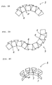
- Figures 1A and 1B show a honeycomb member of an intermediate stage of the production of the final honeycomb member according to the invention.
- As shown in Figures 1A and 1B, each
cell 4 in ahoneycomb member 5 is defined by a series of bottomfirst faces 1, a series oftop faces 2, and interconnectingwalls 3. Each of the first andsecond faces walls 3 has a rectangular surface and creates an equilateral triangular cross section for eachcell 4. A connecting angle θ between eachfirst face 1 and eachwall 3 is about 60 degrees. In thehoneycomb member 5, eachcell 4 is rowed such that thefirst faces 1 are arranged with corners orside edges adjacent cells 4 and having a slight clearance and such that thesecond faces 2 are arranged with corners orside edges adjacent cells 4 with a slight clearance. - As shown in Figures 2A and 2B, when the
honeycomb member 5 is bent to form a radius of curvature, adjoiningside edges support points 6. Thehoneycomb member 5 can then be bent flexibly in any direction on the support points 6. The support points 6, therefore, assure the stable flexibility of thehoneycomb member 5. When thehoneycomb member 5 is bent to a radius of curvature as shown in Figure 2C, adjoiningside edges support lines 7 also assure the stable flexibility of thehoneycomb member 5. The connecting angle θ is so acute that eithersupport points 6 orsupport lines 7 offer adequate and stable flexibility to thehoneycomb member 5, even when the first faces 1, the second faces 2 and thewalls 3 are thin. When the final products are manufactured, specified points P can be soldered. - In the
honeycomb member 5 shown in figures 1A and 1B, the interval between adjoiningside edges cell 4 has a slight clearance therein. Thehoneycomb member 5 can be bent in such a direction that the adjoiningside edges entire honeycomb member 5 is settled. Thehoneycomb member 5 can bend flexibly along support points 6 andlines 7. When thehoneycomb member 5 is bent, the first faces 1 define an inner bend radius. - As aforementioned, the
honeycomb member 5 can be bent as shown in Figures 2A and 2B. Before thehoneycomb member 5 is soldered to a face plate to form a honeycomb panel, thehoneycomb member 5 can also be bent as follows. - As shown in Figures 3A and 3B, upon bending the
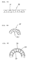
honeycomb member 5, an outer radius R1 and an inner radius R2 are formed. When L denotes the length of thefirst face 1, the bend limitation of thehoneycomb member 5 can be determined by means of the following equations.
honeycomb member 5 onto a face plate. As shown in the above equations, by adjusting the length L of thefirst face 1, small radii of curvature can be permitted. To further decrease the radius of curvature, both ends of eachfirst face 1 of thehoneycomb member 5 can be trimmed according to the curvature of a face plate, thereby minimizing the clearances d1 and d2. - As shown in Figures 4A and 4B, a honeycomb member can also be twisted about the axis defining its length. The hatched portion of the strip material for a honeycomb member can be cut out. The strip material is then folded along folding lines a through i to form a honeycomb member as shown in Figure 4C. This honeycomb member can contact a face plate with only slight clearance therebetween. Therefore, as long as the folding lines a through i are perpendicular to the length of the
honeycomb member 5, the first faces 1, the second faces 2 and thewalls 3 are not limited to a strictly rectangular shape. By cutting the part of the strip material to obtain an appropriate curve, a honeycomb member can be soldered to a face plate easily, thereby following the configuration of a honeycomb panel. - As aforementioned, the honeycomb member according to this invention can be bent or twisted to various radii of curvature. In a honeycomb core composed of the honeycomb member, the load-bearing force acts perpendicularly to the curved surface of the honeycomb core.
- When a honeycomb panel is manufactured, a panel is first pressed to a desired curvature; the honeycomb member of this invention is then arranged onto a panel, and a face plate is fit onto the honeycomb member. Through simple manufacturing steps, the honeycomb member can be bent or twisted as desired. Consequently, a honeycomb panel having a complicated set of curvatures can be easily manufactured. Since the sizes of the cells composing the honeycomb member are easily adjusted, the material thickness, the cell heights and the curvature of the honeycomb core as well as other parameters can each be easily adjusted. Therefore, a honeycomb core or panel having desired strength can be easily manufactured. A honeycomb member can also be manufactured by folding a strip member along a series of parallel folding lines.
- The cells of the intermediate honeycomb member can alternately have an isosceles triangular or other shaped cross section. For example, per Figure 5A,
cells 23 can have a circular cross section composing ahoneycomb member 24. As shown in Figure 5B,cells 25 can have a square cross section and form ahoneycomb member 26. As shown in Figure 5C, in ahoneycomb member 27, curved first faces and second faces can also define cells. In ahoneycomb member 29, per Figure 5D, the first faces, walls and second faces of cells can include foldedreinforcement ribs 28 for strengthening thehoneycomb member 29. In the honeycomb members, 24, 26, 27 and 29 the connecting angle θ between each interconnecting wall and each first face of each cell is acute. Therefore, the honeycomb members, 24, 26, 27 and 29 offer the same effects as those of thehoneycomb member 5 composed of thecells 4. - A first embodiment of a honeycomb panel will now be explained with reference to Figures 6A through 6C. In this embodiment,
cells 31 having an equilateral triangular cross section compose ahoneycomb member 32, in the same way as thehoneycomb member 5 composed of thecells 4 explained above and shown in Figures 1A and 1B. Thehoneycomb member 32 can be used in honeycomb panels having a variety of curvatures. In this embodiment, aluminum strip material is folded to form thehoneycomb member 32, such that three 11mm long sides define thecells 31. The aluminum strip material has a thickness of 0.2mm and a width of 13mm. - As shown in Figure 6B, the
honeycomb member 32 is first bent in the same way as explained with reference to Figure 2A such that an inner radius Ri is 50mm. As shown in Figure 6C,face plates honeycomb member 32, respectively, thereby forming a honeycomb panel. Thehoneycomb member 32 can be bent flexibly and then soldered in place to follow the curvature of theface plates honeycomb member 32 acts perpendicularly to the radius of curvature of theface plates - A second embodiment of a honeycomb panel will now be explained with reference to Figures 7A and 7B. In this embodiment, the
honeycomb member 32 of the above first embodiment is formed in the same way as explained with reference to Figure 2B. Thehoneycomb member 32 is then assembled and soldered betweenface plates face plates honeycomb member 32 follows the compound curvature of the honeycomb panel. Thehoneycomb member 32 is securely soldered between theface plates honeycomb member 32 acts perpendicularly to the compound radii of curvature, thereby offering adequate strength, for example a compressive strength of about 0.7kgf/mm2 to the honeycomb panel. - A further application of the honeycomb members will now be explained with reference to Figure 8. In this embodiment the
honeycomb member 32 is bent as shown in Figure 2C to form a spacer between ahoneycomb core 41 and analuminum block 42 in a honeycomb panel. Thehoneycomb core 41 is composed of known cells having a hexagonal cross section. A screw thread (not shown) is provided in thealuminum block 42. - A bore 43 is made in the
honeycomb core 41 to receive thealuminum block 42. Thehoneycomb member 32 is bent and wound around thealuminum block 42. Thealuminum block 42 is then inserted into thebore 43. Thehoneycomb member 32 secures thealuminum block 42 in the honeycomb panel and strengthens the portion between thealuminum block 42 and thehoneycomb core 41. Thehoneycomb member 32 can thus be used as an individual reinforcement due to its rigidity. At the same time, thehoneycomb member 32 can contour any curve of the panel. - Since the
honeycomb member 32 fills the portion between thealuminum block 42 and thehoneycomb core 41, this portion has the same strength as the other portions of the honeycomb panel and is more resistant to breakage. Thehoneycomb member 32 could also be wound around thealuminum block 42 in several layers without having to bond the layers to one another. - This invention has been described above with reference to preferred embodiments as shown in the drawings. Modifications and alterations may become apparent to one skilled in the art upon reading and understanding the specification.
- It should also be noted that Figures 5A through 5D show the cross sections of various configurations the honeycomb cells have. The cross section of the cells, however, is not restricted to these configurations. The connecting angle between the cell walls and first faces, however, is preferably acute. Since the cross section of the cells is not limited to that of an equilateral triangle, the cells can have an orifice therein. Furthermore, the material of the honeycomb member is not limited to the specified material.
Claims (9)
- A honeycomb member for a honeycomb core or panel, said honeycomb member (5, 24, 26, 27, 29, 32) being elongate and comprising a plurality of rectangular first faces (1) which are sequentially arranged and extend in the axial direction of said member (5, 24, 26, 27, 29, 32) and further comprising interconnecting walls (2, 3) each extending substantially perpendicular to the length of said member (5, 24, 26, 27, 29, 32) and being connected to adjoining side edges (1a, 1b) of two adjoining ones of said first faces (1), said interconnecting walls (1, 2) defining a plurality of axially spaced cells (4, 23, 25, 31), characterized in that said member (5, 24, 26, 27, 29, 32) is bent such that said adjoining side edges (1a, 1b) of said two adjoining ones of said first faces (1) contact each other at least at a portion (6, 7) thereof.
- A honeycomb member according to claim 1 in which the connecting angle formed between the interconnecting walls (2,3) and the axially spaced first faces (1) is less than 90°.
- A honeycomb member according to claim 2 in which the connecting angle is about 60°.
- A honeycomb member according to claim 1 wherein said adjoining side edges (1a,1b) contact each other along a line (7) to form a continuous load bearing surface perpendicular to a radius of curvature which said member (5,24,26,27,29,32) is bent to.
- A honeycomb member according to claim 1 wherein the cells (4) have a substantially triangular cross-section.
- A honeycomb member according to claim 1 wherein the cells (25) have a substantially rectangular cross-section.
- A honeycomb member according to claim 1 in which the cells (23) have a substantially circular cross-section.
- A honeycomb member according to claim 1 in which said member (5,24,26,27,29,32) is made from aluminum.
- A honeycomb panel comprising two face plates (33, 34, 35, 36) and at least one honeycomb member (5, 24, 26, 27, 29, 32) interposed between said two face plates and attached thereto, characterized in that said at least one honeycomb member (5, 24, 26, 27, 29, 32) is arranged as defined by one of claims 1 to 8.
Applications Claiming Priority (2)
| Application Number | Priority Date | Filing Date | Title |
|---|---|---|---|
| JP403324/90 | 1990-12-18 | ||
| JP2403324A JP2532167B2 (en) | 1990-12-18 | 1990-12-18 | Honeycomb structure unit and honeycomb panel |
Publications (2)
| Publication Number | Publication Date |
|---|---|
| EP0491277A1 EP0491277A1 (en) | 1992-06-24 |
| EP0491277B1 true EP0491277B1 (en) | 1996-09-04 |
Family
ID=18513070
Family Applications (1)
| Application Number | Title | Priority Date | Filing Date |
|---|---|---|---|
| EP91121290A Expired - Lifetime EP0491277B1 (en) | 1990-12-18 | 1991-12-11 | A honeycomb member and a honeycomb |
Country Status (4)
| Country | Link |
|---|---|
| US (1) | US5270095A (en) |
| EP (1) | EP0491277B1 (en) |
| JP (1) | JP2532167B2 (en) |
| DE (1) | DE69121862T2 (en) |
Families Citing this family (22)
| Publication number | Priority date | Publication date | Assignee | Title |
|---|---|---|---|---|
| JPH08158863A (en) * | 1994-12-02 | 1996-06-18 | Usui Internatl Ind Co Ltd | Metal honeycomb body |
| US7051489B1 (en) | 1999-08-12 | 2006-05-30 | Hunter Douglas Inc. | Ceiling system with replacement panels |
| US7377084B2 (en) * | 2000-04-24 | 2008-05-27 | Hunter Douglas Inc. | Compressible structural panel |
| US7303641B2 (en) | 2002-12-03 | 2007-12-04 | Hunter Douglas Inc. | Method for fabricating cellular structural panels |
| NZ541180A (en) * | 2002-12-09 | 2009-01-31 | Cascade Designs Inc | Film-based cellular matrix |
| DE102004025667A1 (en) * | 2004-05-26 | 2005-12-22 | Wintermantel, Erich, Dipl.-Volksw. | Core material for lightweight constructions in multi-layer construction |
| US20070022672A1 (en) * | 2005-07-11 | 2007-02-01 | Bachynski Michael R | Hurricane protection harness |
| US7762938B2 (en) | 2006-07-24 | 2010-07-27 | Tessellated Group, Llc | Three-dimensional support structure |
| FR2913137B1 (en) * | 2007-02-28 | 2009-04-03 | Aircelle Sa | METHOD FOR MANUFACTURING AN ACOUSTIC ABSORPTION PANEL, IN PARTICULAR FOR AN AIRCRAFT NACELLE |
| GB0804487D0 (en) | 2008-03-11 | 2008-04-16 | Terram Ltd | Cellular structures |
| US20090235608A1 (en) * | 2008-03-19 | 2009-09-24 | Jan Kosny | Support structures formed from triangular elements |
| US20090235507A1 (en) * | 2008-03-24 | 2009-09-24 | Arthur Henry Cashin | Method Of Repairing A Ballistics Barrier |
| US20090250675A1 (en) * | 2008-03-24 | 2009-10-08 | Arthur Henry Cashin | Vehicle Barrier |
| US20090235813A1 (en) * | 2008-03-24 | 2009-09-24 | Arthur Henry Cashin | Ballistics Barrier |
| US20090235814A1 (en) * | 2008-03-24 | 2009-09-24 | Cashin Arthur H | Mobile Reconfigurable Barricade |
| GB2493007B (en) | 2011-07-21 | 2017-08-30 | Fiberweb Holdings Ltd | Confinement structures for particulate fill materials |
| US8481143B2 (en) | 2011-08-22 | 2013-07-09 | The Boeing Company | Thick curved honeycomb core with minimal forming |
| US9221230B2 (en) | 2011-08-22 | 2015-12-29 | The Boeing Company | Honeycomb structure |
| BR102013020863B1 (en) * | 2012-08-17 | 2020-05-19 | Boeing Co | tape and method for forming a hive structure |
| ITBG20150020A1 (en) * | 2015-04-14 | 2016-10-14 | Milano Politecnico | FLEXIBLE PANEL |
| CN105599416B (en) * | 2015-09-02 | 2018-03-02 | 哈尔滨飞机工业集团有限责任公司 | A kind of big curvature metal decking interlayer part shaping indenture prevention method |
| GB201617840D0 (en) * | 2016-10-21 | 2016-12-07 | Rolls Royce Plc | Complementary structure |
Family Cites Families (8)
| Publication number | Priority date | Publication date | Assignee | Title |
|---|---|---|---|---|
| US2050074A (en) * | 1933-06-20 | 1936-08-04 | Merriam H Trytten | Folded metal section |
| US3068565A (en) * | 1958-10-16 | 1962-12-18 | Nat Distillers Chem Corp | Method of making honeycomb laminate |
| US3432379A (en) * | 1965-10-22 | 1969-03-11 | Atomic Energy Commission | Three dimensional flexible dovetail honeycomb |
| GB1390968A (en) * | 1971-07-28 | 1975-04-16 | Nissan Motor | Honeycomb structures |
| JPS5825531A (en) * | 1981-08-10 | 1983-02-15 | Nippon Denso Co Ltd | Electronically controlled fuel injection device |
| US4411381A (en) * | 1982-04-02 | 1983-10-25 | Nelson C. Ittner | Honeycomb manufacturing method |
| JPS599332A (en) * | 1982-07-06 | 1984-01-18 | Bridgestone Corp | Vibration damping material |
| JPS6393435A (en) * | 1986-10-06 | 1988-04-23 | チバ−ガイギ− アクチエンゲゼルシヤフト | Three-layer folding sheet for laminated panel core |
-
1990
- 1990-12-18 JP JP2403324A patent/JP2532167B2/en not_active Expired - Lifetime
-
1991
- 1991-12-05 US US07/803,099 patent/US5270095A/en not_active Expired - Fee Related
- 1991-12-11 EP EP91121290A patent/EP0491277B1/en not_active Expired - Lifetime
- 1991-12-11 DE DE69121862T patent/DE69121862T2/en not_active Expired - Fee Related
Also Published As
| Publication number | Publication date |
|---|---|
| JP2532167B2 (en) | 1996-09-11 |
| JPH04210829A (en) | 1992-07-31 |
| DE69121862T2 (en) | 1997-02-13 |
| US5270095A (en) | 1993-12-14 |
| EP0491277A1 (en) | 1992-06-24 |
| DE69121862D1 (en) | 1996-10-10 |
Similar Documents
| Publication | Publication Date | Title |
|---|---|---|
| EP0491277B1 (en) | A honeycomb member and a honeycomb | |
| AU2006313679B2 (en) | Method for manufacturing of cellular board, cellular board, method for producing cellular board element of steel plate strip, and production line | |
| US5431980A (en) | Formable cellular material with synclastic behavior | |
| JPS6028980B2 (en) | I-beam | |
| US3227600A (en) | Formable honeycomb | |
| US5380579A (en) | Honeycomb panel with interlocking core strips | |
| US4291515A (en) | Structural elements | |
| US5064493A (en) | Method of producing curved honeycomb core material having crimps in one edge | |
| CA2431217C (en) | Flanged honeycomb core and method of making same | |
| JPH0622957B2 (en) | Honeycomb structure for coating curved surfaces and method of making the same | |
| US3205109A (en) | Method of making a honeycomb type structure | |
| AU2011253543B2 (en) | System and Method for Manufacturing Cellular Board | |
| US4491265A (en) | Method of aligning honeycomb cells | |
| JP2842751B2 (en) | Rigid board | |
| JP3010925B2 (en) | Brazed laminated panel and method of manufacturing the same | |
| JP3479587B2 (en) | Manufacturing method of honeycomb core for curved surface forming | |
| JPS6115223B2 (en) | ||
| RU2084349C1 (en) | Volumetric member for honeycomb structure and process of manufacture of three-layer honeycomb structures with its usage | |
| EP0543636B1 (en) | Panel structure and method for producing panel | |
| AU2011253738B2 (en) | Method for Manufacturing Cellular Board and a Cellular Board | |
| JPH0486252A (en) | Honeycomb material | |
| JPH0622955B2 (en) | Manufacturing method of honeycomb panel structure | |
| JP2579503B2 (en) | Honeycomb core | |
| JPS6138307B2 (en) | ||
| JPH02171231A (en) | Honeycomb structure |
Legal Events
| Date | Code | Title | Description |
|---|---|---|---|
| PUAI | Public reference made under article 153(3) epc to a published international application that has entered the european phase |
Free format text: ORIGINAL CODE: 0009012 |
|
| AK | Designated contracting states |
Kind code of ref document: A1 Designated state(s): DE FR GB IT |
|
| 17P | Request for examination filed |
Effective date: 19921214 |
|
| 17Q | First examination report despatched |
Effective date: 19940628 |
|
| GRAH | Despatch of communication of intention to grant a patent |
Free format text: ORIGINAL CODE: EPIDOS IGRA |
|
| GRAA | (expected) grant |
Free format text: ORIGINAL CODE: 0009210 |
|
| GRAH | Despatch of communication of intention to grant a patent |
Free format text: ORIGINAL CODE: EPIDOS IGRA |
|
| AK | Designated contracting states |
Kind code of ref document: B1 Designated state(s): DE FR GB IT |
|
| REF | Corresponds to: |
Ref document number: 69121862 Country of ref document: DE Date of ref document: 19961010 |
|
| ET | Fr: translation filed | ||
| ITF | It: translation for a ep patent filed |
Owner name: SAIC BREVETTI S.R.L. |
|
| PLBE | No opposition filed within time limit |
Free format text: ORIGINAL CODE: 0009261 |
|
| STAA | Information on the status of an ep patent application or granted ep patent |
Free format text: STATUS: NO OPPOSITION FILED WITHIN TIME LIMIT |
|
| 26N | No opposition filed | ||
| PGFP | Annual fee paid to national office [announced via postgrant information from national office to epo] |
Ref country code: GB Payment date: 19991126 Year of fee payment: 9 |
|
| PGFP | Annual fee paid to national office [announced via postgrant information from national office to epo] |
Ref country code: FR Payment date: 19991217 Year of fee payment: 9 |
|
| PGFP | Annual fee paid to national office [announced via postgrant information from national office to epo] |
Ref country code: DE Payment date: 20000131 Year of fee payment: 9 |
|
| PG25 | Lapsed in a contracting state [announced via postgrant information from national office to epo] |
Ref country code: GB Free format text: LAPSE BECAUSE OF NON-PAYMENT OF DUE FEES Effective date: 20001211 |
|
| GBPC | Gb: european patent ceased through non-payment of renewal fee |
Effective date: 20001211 |
|
| PG25 | Lapsed in a contracting state [announced via postgrant information from national office to epo] |
Ref country code: FR Free format text: LAPSE BECAUSE OF NON-PAYMENT OF DUE FEES Effective date: 20010831 |
|
| REG | Reference to a national code |
Ref country code: FR Ref legal event code: ST |
|
| PG25 | Lapsed in a contracting state [announced via postgrant information from national office to epo] |
Ref country code: DE Free format text: LAPSE BECAUSE OF NON-PAYMENT OF DUE FEES Effective date: 20011002 |
|
| PG25 | Lapsed in a contracting state [announced via postgrant information from national office to epo] |
Ref country code: IT Free format text: LAPSE BECAUSE OF NON-PAYMENT OF DUE FEES;WARNING: LAPSES OF ITALIAN PATENTS WITH EFFECTIVE DATE BEFORE 2007 MAY HAVE OCCURRED AT ANY TIME BEFORE 2007. THE CORRECT EFFECTIVE DATE MAY BE DIFFERENT FROM THE ONE RECORDED. Effective date: 20051211 |