EP0490734A1 - Method and device for the automatic adjustment of a reflective surface - Google Patents
Method and device for the automatic adjustment of a reflective surface Download PDFInfo
- Publication number
- EP0490734A1 EP0490734A1 EP91403299A EP91403299A EP0490734A1 EP 0490734 A1 EP0490734 A1 EP 0490734A1 EP 91403299 A EP91403299 A EP 91403299A EP 91403299 A EP91403299 A EP 91403299A EP 0490734 A1 EP0490734 A1 EP 0490734A1
- Authority
- EP
- European Patent Office
- Prior art keywords
- reflecting surface
- around
- axis
- automatic positioning
- reference point
- Prior art date
- Legal status (The legal status is an assumption and is not a legal conclusion. Google has not performed a legal analysis and makes no representation as to the accuracy of the status listed.)
- Withdrawn
Links
Images

Classifications
-
- H—ELECTRICITY
- H01—ELECTRIC ELEMENTS
- H01Q—ANTENNAS, i.e. RADIO AERIALS
- H01Q3/00—Arrangements for changing or varying the orientation or the shape of the directional pattern of the waves radiated from an antenna or antenna system
- H01Q3/02—Arrangements for changing or varying the orientation or the shape of the directional pattern of the waves radiated from an antenna or antenna system using mechanical movement of antenna or antenna system as a whole
- H01Q3/08—Arrangements for changing or varying the orientation or the shape of the directional pattern of the waves radiated from an antenna or antenna system using mechanical movement of antenna or antenna system as a whole for varying two co-ordinates of the orientation
-
- B—PERFORMING OPERATIONS; TRANSPORTING
- B60—VEHICLES IN GENERAL
- B60R—VEHICLES, VEHICLE FITTINGS, OR VEHICLE PARTS, NOT OTHERWISE PROVIDED FOR
- B60R1/00—Optical viewing arrangements; Real-time viewing arrangements for drivers or passengers using optical image capturing systems, e.g. cameras or video systems specially adapted for use in or on vehicles
- B60R1/02—Rear-view mirror arrangements
- B60R1/06—Rear-view mirror arrangements mounted on vehicle exterior
- B60R1/062—Rear-view mirror arrangements mounted on vehicle exterior with remote control for adjusting position
- B60R1/07—Rear-view mirror arrangements mounted on vehicle exterior with remote control for adjusting position by electrically powered actuators
- B60R1/072—Rear-view mirror arrangements mounted on vehicle exterior with remote control for adjusting position by electrically powered actuators for adjusting the mirror relative to its housing
-
- G—PHYSICS
- G05—CONTROLLING; REGULATING
- G05B—CONTROL OR REGULATING SYSTEMS IN GENERAL; FUNCTIONAL ELEMENTS OF SUCH SYSTEMS; MONITORING OR TESTING ARRANGEMENTS FOR SUCH SYSTEMS OR ELEMENTS
- G05B19/00—Programme-control systems
- G05B19/02—Programme-control systems electric
- G05B19/18—Numerical control [NC], i.e. automatically operating machines, in particular machine tools, e.g. in a manufacturing environment, so as to execute positioning, movement or co-ordinated operations by means of programme data in numerical form
- G05B19/406—Numerical control [NC], i.e. automatically operating machines, in particular machine tools, e.g. in a manufacturing environment, so as to execute positioning, movement or co-ordinated operations by means of programme data in numerical form characterised by monitoring or safety
- G05B19/4061—Avoiding collision or forbidden zones
-
- G—PHYSICS
- G05—CONTROLLING; REGULATING
- G05B—CONTROL OR REGULATING SYSTEMS IN GENERAL; FUNCTIONAL ELEMENTS OF SUCH SYSTEMS; MONITORING OR TESTING ARRANGEMENTS FOR SUCH SYSTEMS OR ELEMENTS
- G05B2219/00—Program-control systems
- G05B2219/30—Nc systems
- G05B2219/34—Director, elements to supervisory
- G05B2219/34215—Microprocessor
-
- G—PHYSICS
- G05—CONTROLLING; REGULATING
- G05B—CONTROL OR REGULATING SYSTEMS IN GENERAL; FUNCTIONAL ELEMENTS OF SUCH SYSTEMS; MONITORING OR TESTING ARRANGEMENTS FOR SUCH SYSTEMS OR ELEMENTS
- G05B2219/00—Program-control systems
- G05B2219/30—Nc systems
- G05B2219/37—Measurements
- G05B2219/37462—Resistor, potentiometers
-
- G—PHYSICS
- G05—CONTROLLING; REGULATING
- G05B—CONTROL OR REGULATING SYSTEMS IN GENERAL; FUNCTIONAL ELEMENTS OF SUCH SYSTEMS; MONITORING OR TESTING ARRANGEMENTS FOR SUCH SYSTEMS OR ELEMENTS
- G05B2219/00—Program-control systems
- G05B2219/30—Nc systems
- G05B2219/45—Nc applications
- G05B2219/45185—Auto mirror
-
- G—PHYSICS
- G05—CONTROLLING; REGULATING
- G05B—CONTROL OR REGULATING SYSTEMS IN GENERAL; FUNCTIONAL ELEMENTS OF SUCH SYSTEMS; MONITORING OR TESTING ARRANGEMENTS FOR SUCH SYSTEMS OR ELEMENTS
- G05B2219/00—Program-control systems
- G05B2219/30—Nc systems
- G05B2219/49—Nc machine tool, till multiple
- G05B2219/49143—Obstacle, collision avoiding control, move so that no collision occurs
Definitions
- the invention relates to an automatic action method and device for replacing a reflecting surface such as a mirror glass in a previously memorized position.
- the publication FR 2.509.675 describes a memorized rear view mirror, the mirror support of which is mounted on a base and can pivot around two independent axes. This support is coupled to the shafts of two electrically controlled adjustment motors, which can be supplied selectively. At least one adjustable nominal position of the support, relative to the two axes, is memorized under the control of the driver. A return to the memorized position is possible by reading the memorized position information and the appropriate control of the adjustment motors.
- the invention provides a method and a device eliminating any risk of blockage. It finds in particular its application on an exterior mirror of a motor vehicle; however, this application does not limit the scope of the invention, which can be implemented on other types of functional surfaces articulated around two axes.
- the invention relates to an automatic positioning method, with memory recall, of a reflective surface mounted on a ball joint allowing its angular displacement with the same amplitude relative to a central position around a first up-down pivot axis, and around a second left-right pivot axis.
- This method is characterized in that the reflective surface is coupled to top-bottom and left-right position sensors, the output voltages of which are exploited in order to impose its trajectory at a fixed reference point relative to the reflective surface , during automatic positioning of the latter in a target position recalled in memory.
- the reference point moves rectilinearly during the angular displacement of the reflecting surface around the first axis and during its displacement around the second axis, so that it can geometrically join the target position by two different waypoints, defining with the starting point and this target position, a rectangle.
- the coordinates of the two possible crossing points are calculated from the coordinates of the target position and the starting position of the reference point.
- the reference point is located on the normal to the center of the reflecting surface, and can move inside a circle delimiting all the positions of the reflecting surface authorized by the kneecap.
- the path imposed on the reflecting surface corresponds to the point of passage closest to the center of the circle.
- the reflecting surface is moved first around the pivot axis right-left until the reference point reaches the right-left coordinate of the target position.
- the reflecting surface is moved first around the up-down pivot axis until the reference point reaches the up-down coordinate of the target position.
- the invention also relates to an automatic positioning device with memory recall of a reflective surface mounted on a ball joint allowing its movement with the same amplitude around two orthogonal axes.
- This device comprises a first motor driving through a first pinion a first rack whose longitudinal displacement rotates the reflecting surface around the first axis, and a second motor driving, via a second pinion a second rack whose displacement longitudinal rotates the reflecting surface around the second axis. It also includes a first position sensor determining the position of the reflecting surface around the first axis and a second position sensor determining the position of the reflecting surface around the second axis.
- This device is characterized in that the output voltages of the first and of the second sensor are used to determine which motor must be actuated first, during the automatic positioning of the reflecting surface towards a position recalled in memory.
- the first and the second rack are parallel, each being orthogonal to the axis around which it rotates the reflecting surface, and carry at one of their ends a spherical articulation head on which is engaged by clipping a cap secured to the reflecting surface.
- the first and the second sensor are connected to a unit for acquiring parameter values, and deliver signals to the position memory of the central unit, operating buttons, memory buttons and memory recall buttons provide instructions to the central unit, the central unit delivers to a power control block excitation signals from the first and from the second motor, for positioning the surface reflecting around the first and second axis in a determined order.
- the reflecting surface is a rear-view mirror.
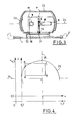
- the mirror shown in FIG. 1 comprises a support 2 articulated on a base 3 and a reflecting surface or mirror 4. Behind the reflecting surface 4 are housed the articulation ball 22, 23, a first motor 5, responsible for the positioning up bottom of the reflecting surface 4, a first pinion 6 driven by the first motor 5, and the first corresponding rack 7 on which the first pinion 6 is engaged, a first position sensor 8 or up-down position sensor, being associated to the first motor 5.
- the second motor 9, responsible for the left-right positioning of the reflecting surface 4 is provided with a second output pinion 10, engaged on a second rack 11.
- the second motor 9 is associated with a second sensor position sensor 12, or left-right position sensor 12 of the reflecting surface 4.
- a set of electrical connection cables not shown respectively connects the first motor 5, the first sensor 8, the second motor 9, and the second sensor 12 to the central control unit of the device 17, on board the vehicle.
- FIGs 2 and 3 show that each rack 7-11 is provided at one of its ends with a spherical head 18-19 on which is engaged by clipping a cap 20-21 secured to the reflecting surface 4.
- the structure of the ball joint 22, 23 is highlighted in Figure 3, where it is also seen that the teeth of the first and second rack 7-11 are perpendicular to each other.
- the ball joint 22, 23 allows, thanks to the movement of the racks 7-11 in front of the pinions 6-10, the pivoting of the reflecting surface 4 around two orthogonal axes 24-25 called respectively up-down pivot axis 24, and left-right pivot axis 25.
- the pivoting of the reflecting surface 4 is determined by the structure of the ball 22, 23 and the length of the racks 7-11. Conventionally, the possibilities of up-down movement of the reflecting surface 4 are all the more limited as one approaches the extreme positions all to the left or all to the right.
- the circle 26 is shown in Figure 4 in an orthonormal coordinate system.
- the abscissa x and the ordinate y of each point M placed in this coordinate system represent the position coordinates of the reference point M around the two pivot axes 24-25.
- Figure 4 shows that to move the reference point M from a starting position A to an ending position or target position C, not located on a line parallel to the horizontal axis 24 or the vertical axis 25, there are two possible trajectories. Each of these trajectories is made up of two orthogonal segments corresponding to the respective actuation of each motor. They together form a rectangle (A - B - C - D). Reading this diagram, we can see that certain trajectories are impossible to perform, because they leave all the authorized positions at the reference point M, delimited by the circle 26.
- the rectangle having for its summit the starting point A, the two theoretical points of, passage B, D, and the target position C highlights that, when a first trajectory is impossible because it leaves the circle of authorized positions, the second trajectory, on the other hand is possible.
- the invention proposes a control strategy allowing the reflective surface 4 to always engage on a possible trajectory. This strategy is as follows:
- the reflecting surface 4 is moved first around the left-right pivot axis 25,
- the reflective surface is first moved around the up-down pivot axis 24.
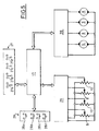
- the control assembly shown in FIG. 5 comprises a central unit 17 provided with a microprocessor, to which are connected a manual control block 27, a block of storage 28, a block for acquiring position information 29, and a power control block 30.
- the memory block has a memory key 28a, and several memory recall keys, for example three, 28b, 28c, 28d.
- the position information acquisition block 29 receives the information transmitted by the up-down and right-left position sensors of the driver's rear view mirror 8, 12, and of the passenger's rear view mirror 8 ′, 12 ′.
- the power control block 30 sends orders to the up-down and right-left actuation motors of the driver's mirror 5, 9 and of the passenger's mirror 5 ′, 9 ′.
- Appendix Calculations determining the strategy of displacement of the reflecting surface.
Landscapes
- Engineering & Computer Science (AREA)
- Multimedia (AREA)
- Mechanical Engineering (AREA)
- Human Computer Interaction (AREA)
- Manufacturing & Machinery (AREA)
- Physics & Mathematics (AREA)
- General Physics & Mathematics (AREA)
- Automation & Control Theory (AREA)
- Control Of Position Or Direction (AREA)
- Rear-View Mirror Devices That Are Mounted On The Exterior Of The Vehicle (AREA)
Abstract
Description
L'invention concerne un procédé et un dispositif à action automatique permettant de replacer une surface réfléchissante telle qu'une glace de rétroviseur dans une position préalablement mémorisée.The invention relates to an automatic action method and device for replacing a reflecting surface such as a mirror glass in a previously memorized position.
La publication FR 2.509.675 décrit un rétroviseur mémorisé, dont le support du miroir est monté sur un socle et peut pivoter autour de deux axes indépendants. Ce support est couplé aux arbres de deux moteurs de réglage commandés électriquement, et pouvant être alimentés sélectivement. Au moins une position nominale réglable du support, par rapport aux deux axes, est mémorisée sous la commande du conducteur. Un retour dans la position mémorisée est possible par la lecture des informations de position mémorisées, et la commande appropriée des moteurs de réglage.The publication FR 2.509.675 describes a memorized rear view mirror, the mirror support of which is mounted on a base and can pivot around two independent axes. This support is coupled to the shafts of two electrically controlled adjustment motors, which can be supplied selectively. At least one adjustable nominal position of the support, relative to the two axes, is memorized under the control of the driver. A return to the memorized position is possible by reading the memorized position information and the appropriate control of the adjustment motors.
Ce type de dispositif, bien que satisfaisant sur de nombreux plans présente toutefois un inconvénient majeur. En effet, pour déplacer le rétroviseur d'une position de départ à une position cible rappelée en mémoire, en actionnant successivement les deux moteurs de réglage, il existe deux trajectoires possibles, selon l'ordre d'actionnement des moteurs. Il n'est pas rare que l'une de ces deux trajectoires sorte de l'ensemble des positions permises au rétroviseur par son système d'articulation. De fait, si l'ordre d'actionnement des moteurs est imposé par la logique de commande, le rétroviseur ne pourra pas rejoindre la position rappelée en mémoire, dans le cas où la trajectoire imposée sort de l'ensemble des positions autorisées.This type of device, although satisfactory in many respects, however has a major drawback. Indeed, to move the mirror from a starting position to a target position recalled in memory, by successively actuating the two adjustment motors, there are two possible trajectories, according to the order of actuation of the motors. It is not uncommon for one of these two trajectories to come out of the set of positions permitted to the mirror by its articulation system. In fact, if the engine actuation order is imposed by the control unit, the mirror will not be able to reach the position recalled in memory, in the event that the imposed trajectory leaves all the authorized positions.
Pour pallier à cet inconvénient, l'invention propose un procédé et un dispositif supprimant tout risque de blocage. Elle trouve notamment son application sur un rétroviseur extérieur de véhicule automobile ; toutefois, cette application ne limite pas la portée de l'invention, qui peut être mise en oeuvre sur d'autres types de surfaces fonctionnelles articulées autour de deux axes.To overcome this drawback, the invention provides a method and a device eliminating any risk of blockage. It finds in particular its application on an exterior mirror of a motor vehicle; however, this application does not limit the scope of the invention, which can be implemented on other types of functional surfaces articulated around two axes.
L'invention concerne un procédé de positionnement automatique, avec rappel de mémoire, d'une surface réfléchissante montée sur une rotule autorisant avec la même amplitude son déplacement angulaire par rapport à une position centrale autour d'un premier axe de pivotement haut-bas, et autour d'un second axe de pivotement gauche-droite. Ce procédé est caractérisé en ce que la surface réfléchissante est couplée à des capteurs de position haut-bas et gauche-droite, dont les tensions de sortie sont exploitées afin d'imposer sa trajectoire à un point de référence fixe par rapport à la surface réfléchissante, lors du positionnement automatique de celle-ci dans une position cible rappelée en mémoire.The invention relates to an automatic positioning method, with memory recall, of a reflective surface mounted on a ball joint allowing its angular displacement with the same amplitude relative to a central position around a first up-down pivot axis, and around a second left-right pivot axis. This method is characterized in that the reflective surface is coupled to top-bottom and left-right position sensors, the output voltages of which are exploited in order to impose its trajectory at a fixed reference point relative to the reflective surface , during automatic positioning of the latter in a target position recalled in memory.
Selon un mode de réalisation de l'invention, le point de référence se déplace de façon rectiligne lors du déplacement angulaire de la surface réfléchissante autour du premier axe et lors de son déplacement autour du second axe, si bien qu'il peut rejoindre géométriquement la position cible par deux points de passage différents, définissant avec le point de départ et cette position cible, un rectangle.According to one embodiment of the invention, the reference point moves rectilinearly during the angular displacement of the reflecting surface around the first axis and during its displacement around the second axis, so that it can geometrically join the target position by two different waypoints, defining with the starting point and this target position, a rectangle.
Selon un mode de réalisation de l'invention, les coordonnées des deux points de passage possibles sont calculées à partir des coordonnées de la position cible et de la position de départ du point de référence.According to one embodiment of the invention, the coordinates of the two possible crossing points are calculated from the coordinates of the target position and the starting position of the reference point.
Selon un mode de réalisation de l'invention, le point de référence est situé sur la normale au centre de la surface réfléchissante, et peut se déplacer à l'intérieur d'un cercle délimitant l'ensemble des positions de la surface réfléchissante autorisées par la rotule.According to one embodiment of the invention, the reference point is located on the normal to the center of the reflecting surface, and can move inside a circle delimiting all the positions of the reflecting surface authorized by the kneecap.
Selon un mode de réalisation de l'invention, la trajectoire imposée à la surface réfléchissante correspond au point de passage le plus proche du centre du cercle.According to one embodiment of the invention, the path imposed on the reflecting surface corresponds to the point of passage closest to the center of the circle.
Selon un mode de réalisation de l'invention, si le point de passage le plus proche du centre du cercle a la même coordonnée haut-bas que le point de départ, la surface réfléchissante est déplacée en premier lieu autour de l'axe de pivotement droite-gauche jusqu'à ce que le point de référence atteigne la coordonnée droite-gauche de la position cible.According to one embodiment of the invention, if the passage point closest to the center of the circle has the same up-down coordinate as the starting point, the reflecting surface is moved first around the pivot axis right-left until the reference point reaches the right-left coordinate of the target position.
Selon un mode de réalisation de l'invention, si le point de passage le plus proche du centre du cercle n'a pas la même coordonnée haut-bas que le point de départ, la surface réfléchissante est déplacée en premier lieu autour de l'axe de pivotement haut-bas jusqu'à ce que le point de référence atteigne la coordonnée haut-bas de la position cible.According to an embodiment of the invention, if the crossing point closest to the center of the circle does not have the same up-down coordinate as the starting point, the reflecting surface is moved first around the up-down pivot axis until the reference point reaches the up-down coordinate of the target position.
L'invention concerne également un dispositif de positionnement automatique avec rappel de mémoire d'une surface réfléchissante montée sur une rotule autorisant avec la même amplitude son déplacement autour de deux axes orthogonaux. Ce dispositif comporte un premier moteur entrainant par l'intermédiaire d'un premier pignon une première crémaillère dont le déplacement longitudinal fait tourner la surface réfléchissante autour du premier axe, et un second moteur entrainant, par l'intermédiaire d'un second pignon une seconde crémaillère dont le déplacement longitudinal fait tourner la surface réfléchissante autour du second axe. Il comporte également un premier capteur de position déterminant la position de la surface réfléchissante autour du premier axe et un second capteur de position déterminant la position de la surface réfléchissante autour du second axe. Ce dispositif est caractérisé en ce que les tensions de sortie du premier et du second capteur sont exploitées pour déterminer quel moteur doit être actionné en premier, lors du positionnement automatique de la surface réfléchissante vers une position rappelée en mémoire.The invention also relates to an automatic positioning device with memory recall of a reflective surface mounted on a ball joint allowing its movement with the same amplitude around two orthogonal axes. This device comprises a first motor driving through a first pinion a first rack whose longitudinal displacement rotates the reflecting surface around the first axis, and a second motor driving, via a second pinion a second rack whose displacement longitudinal rotates the reflecting surface around the second axis. It also includes a first position sensor determining the position of the reflecting surface around the first axis and a second position sensor determining the position of the reflecting surface around the second axis. This device is characterized in that the output voltages of the first and of the second sensor are used to determine which motor must be actuated first, during the automatic positioning of the reflecting surface towards a position recalled in memory.
Selon un mode de réalisation de l'invention, la première et la seconde crémaillère sont parallèles, chacune étant orthogonale à l'axe autour duquel elle fait tourner la surface réfléchissante, et portent à l'une de leurs extrémités une tête d'articulation sphérique sur laquelle est engagée par clipsage une calotte solidaire de la surface réfléchissante.According to one embodiment of the invention, the first and the second rack are parallel, each being orthogonal to the axis around which it rotates the reflecting surface, and carry at one of their ends a spherical articulation head on which is engaged by clipping a cap secured to the reflecting surface.
Selon un mode de réalisation de l'invention, le premier et le second capteur sont branchés sur une unité d'acquisition de valeurs de paramètres, et délivrent des signaux à la mémoire de position de l'unité centrale, des boutons de manoeuvre, des boutons de mémorisation et des boutons de rappel de mémoire fournissent des instructions à l'unité centrale, l'unité centrale délivre à un bloc de commande en puissance des signaux d'excitation du premier et du second moteur, pour effectuer le positionnement de la surface réfléchissante autour du premier et du second axe dans un ordre déterminé.According to one embodiment of the invention, the first and the second sensor are connected to a unit for acquiring parameter values, and deliver signals to the position memory of the central unit, operating buttons, memory buttons and memory recall buttons provide instructions to the central unit, the central unit delivers to a power control block excitation signals from the first and from the second motor, for positioning the surface reflecting around the first and second axis in a determined order.
Selon un mode de réalisation de l'invention, la surface réfléchissante est un miroir de rétroviseur.According to one embodiment of the invention, the reflecting surface is a rear-view mirror.
D'autres caractéristiques et avantages de l'invention apparaitront à la lecture de la description suivante d'un mode de réalisaltion de l'invention, en liaison avec les dessins annexés sur lesquels :
- la figure 1 est une vue de face du rétroviseur sur son support, laissant apparaitre en transparence derrière la surface de la glace, les moteurs de positionnement du rétroviseur,
- la figure 2 représente un moteur de positionnement,
- la figure 3 est une coupe selon III - III de la figure 1,
- la figure 4 se rapporte aux coordonnées de position d'un point de référence de la surface réfléchissante,
- la figure 5 est un schéma fonctionnel des organes de commande du dispositif.
- FIG. 1 is a front view of the mirror on its support, revealing in transparency behind the surface of the glass, the positioning motors of the mirror,
- FIG. 2 represents a positioning motor,
- FIG. 3 is a section on III - III of FIG. 1,
- FIG. 4 relates to the position coordinates of a reference point of the reflecting surface,
- Figure 5 is a block diagram of the control members of the device.
Le rétroviseur représenté sur la figure 1 comporte un support 2 articulé sur un socle 3 et une surface réfléchissante ou miroir 4. Derrière la surface réfléchissante 4 sont logés la rotule d'articulation 22, 23, un premier moteur 5, responsable du positionnement haut-bas de la surface réfléchissante 4, un premier pignon 6 entrainé par le premier moteur 5, et la première crémaillère 7 correspondante sur laquelle est en prise le premier pignon 6, un premier capteur de position 8 ou capteur de position haut-bas, étant associé au premier moteur 5. Le second moteur 9, responsable du positionnement gauche-droite de la surface réfléchissante 4 est muni d'un second pignon de sortie 10, en prise sur une seconde crémaillère 11. Le second moteur 9 est associé à un second capteur de position 12, ou capteur de position gauche-droite 12 de la surface réfléchissante 4.The mirror shown in FIG. 1 comprises a
Un ensemble de cables de liaison électrique non représenté relie respectivement le premier moteur 5, le premier capteur 8, le second moteur 9, et le second capteur 12 à l'unité centrale de commande du dispositif 17, embarquée sur le véhicule.A set of electrical connection cables not shown respectively connects the
Les figures 2 et 3 montrent que chaque crémaillère 7-11 est pourvue à une de ses extrémités d'une tête sphérique 18-19 sur laquelle est engagée par clipsage une calotte 20-21 solidaire de la surface réfléchissante 4. La structure de la rotule 22, 23 est mise en évidence sur la figure 3, où on voit également que les dentures de la première et de la seconde crémaillère 7- 11 sont perpendiculaires l'une à l'autre.Figures 2 and 3 show that each rack 7-11 is provided at one of its ends with a spherical head 18-19 on which is engaged by clipping a cap 20-21 secured to the reflecting
Sous l'action du premier et du second moteur 5-9 la rotule 22, 23 permet grâce au défilement des crémaillères 7-11 devant les pignons 6-10, le pivotement de la surface réfléchissante 4 autour de deux axes orthogonaux 24-25 appelés respectivement axe de pivotement haut-bas 24, et axe de pivotement gauche-droite 25.Under the action of the first and second motors 5-9, the
Le pivotement de la surface réfléchissante 4 est déterminé par la structure de la rotule 22, 23 et la longueur des crémaillères 7-11. De façon classique, les possibilités de débattement haut-bas de la surface réfléchissante 4 sont d'autant plus limitées qu'on se rapproche des positions extrêmes tout à gauche ou tout à droite.The pivoting of the reflecting
De même, les possibilités de débattement gauche-droite sont d'autant plus limitées qu'on se rapproche des positions extrêmes tout en haut ou tout en bas. La surface réfléchissante 4 a en fait la possibilité de se déplacer entre ces quatre positions extrêmes. Si on considère la normale au plan de la surface réfléchissante en son centre, tout point de cette droite, y compris son point d'intersection avec le plan, évolue à l'intérieur d'un cercle 26 centré sur la position O de ce point M qui correspond à la position centrale de la surface 4, vis-à-vis des deux axes de positionnement 24-25. Soit M un point de référence choisi arbitrairement sur la normale.Similarly, the possibilities of left-right travel are all the more limited as one approaches the extreme positions at the very top or at the very bottom. The reflecting
Le cercle 26 est représenté sur la figure 4 dans un repère orthonormé. L'abcisse x et l'ordonnée y de chaque point M placé dans ce repère représentent les coordonnées de position du point de référence M autour des deux axes de pivotement 24-25. Sur l'axe horizontal 24, on lit la coordonnée x de position gauche-droite du point de référence M, et sur l'axe vertical 25 on lit sa coordonnée y de position haut-bas.The
La figure 4 met en évidence que pour déplacer le point de référence M d'une position de départ A à une position d'arrivée ou position cible C, non située sur une ligne parallèle à l'axe horizontal 24 ou à l'axe vertical 25, il existe deux trajectoires possibles. Chacune de ces trajectoires est constituée de deux segments orthogonaux correspondants à l'actionnement respectif de chaque moteur. Elles forment ensemble un rectangle (A - B - C - D). A la lecture de ce schéma on s'aperçoit que certaines trajectoires sont impossibles à effectuer, parce qu'elles sortent de l'ensemble des positions autorisées au point de référence M, délimité par le cercle 26.Figure 4 shows that to move the reference point M from a starting position A to an ending position or target position C, not located on a line parallel to the
Ceci signifie que, pour certains réglages mémorisés, le choix arbitraire de l'ordre d'actionnement des moteurs peut conduire un blocage : dans ce cas, le point de référence M ne peut rejoindre la position cible C rappelée en mémoire, et il en résulte un mauvais réglage, dont le conducteur ne sera pas satisfait.This means that, for certain memorized settings, the arbitrary choice of the actuation order of the motors can lead to a blocking: in this case, the reference point M cannot reach the target position C recalled in memory, and this results a wrong setting, with which the driver will not be satisfied.
Le rectangle ayant pour sommet le point de départ A, les deux points de ,passage théoriques B, D, et la position cible C met en évidence que, lorsqu'une première trajectoire est impossible car elle sort du cercle des positions autorisées, la seconde trajectoire, par contre est possible. L'invention propose une stratégie de commande permettant à la surface réfléchissante 4, de s'engager toujours sur une trajectoire possible. Cette stratégie est la suivante :The rectangle having for its summit the starting point A, the two theoretical points of, passage B, D, and the target position C highlights that, when a first trajectory is impossible because it leaves the circle of authorized positions, the second trajectory, on the other hand is possible. The invention proposes a control strategy allowing the
- Si le point de passage le plus proche du centre du cercle a la même coordonnée haut-bas y que le point de départ A, la surface réfléchissante 4 est déplacée en premier lieu autour de l'axe de pivotement gauche-droite 25,- If the crossing point closest to the center of the circle has the same up-down y coordinate as the starting point A, the reflecting
- Si le point de passage le plus proche du centre du cercle a la même coordonnée x gauche-droite que le point de départ, la surface réfléchissante est déplacée en premier lieu autour de l'axe de pivotement haut-bas 24.- If the crossing point closest to the center of the circle has the same x left-right coordinate as the starting point, the reflective surface is first moved around the up-down
Ainsi, en choisissant judicieusement quel moteur 5, 9 doit être actionné en premier, tous les réglages autorisés par la structure géométrique de la rotule 23, et mémorisés, peuvent être effectués, quelque soit la position de départ.Thus, by judiciously choosing which
Cette stratégie, développée pour des miroirs de rétroviseurs, peut être appliquée à d'autres systèmes articulés sur une rotule tels qu'une antenne parabolique. Les calculs sur lesquels elle repose sont explicités en annexe.This strategy, developed for rear-view mirrors, can be applied to other systems articulated on a ball joint such as a satellite dish. The calculations on which it is based are explained in the appendix.
L'ensemble de commande représenté sur la figure 5 comporte une unité centrale 17 munie d'un microprocesseur, à laquelle sont reliés un bloc de commande manuelle 27, un bloc de mémorisation 28, un bloc d'acquisition des informations 29 de position, et un bloc de commande en puissance 30.The control assembly shown in FIG. 5 comprises a
Le bloc de commande manuelle 27 présente :
- une touche de commande haut-bas du rétroviseur conducteur 27a,
- une touche de commande gauche-droite du rétroviseur conducteur 27b,
- une touche de commande haut-bas du rétroviseur passager 27c
- une touche de commande gauche-droite du rétroviseur passager 27d.
- a top-down control button for the driver's mirror 27a,
- a left-right control button for the driver's rear view mirror 27b,
- up-down control button for
passenger mirror 27c - a left-right control button for the
passenger mirror 27d.
Le bloc de mémorisation présente une touche de mémorisation 28a, et plusieurs touches de rappel de mémoire, par exemple trois, 28b, 28c, 28d.The memory block has a memory key 28a, and several memory recall keys, for example three, 28b, 28c, 28d.
Le bloc d'acquisition d'informations 29 de position reçoit les informations émises par les capteurs de position haut-bas et droite-gauche du rétroviseur conducteur 8, 12, et du rétroviseur passager 8′, 12′.The position
Enfin le bloc de commande en puissance 30 envoie des ordres aux moteurs d'actionnement haut-bas et droite-gauche du rétroviseur conducteur 5, 9 et du rétroviseur passager 5′, 9′.Finally, the
Annexe : Calculs déterminant la stratégie du déplacement de la surface réfléchissante. Appendix : Calculations determining the strategy of displacement of the reflecting surface.
Soient xo et yo les coordonnées du point O, centre d'articulation de la surface réfléchissante, apparaissant sur la figure 4. Le choix de la trajectoire adoptée par le point de référence M (x, y) pour passer d'une position de départ A (x₁, y₁) à une position d'arrivée B (x₂, y₂) nécessite les calculs suivants :
- 1) Déterminer pour le point de départ A, son écart par rapport à la position centrale, dans le sens horizontal puis dans le sens vertical.
- a) Ecart horizontal

- b) Ecart vertical

- a) Ecart horizontal
- 2) Déterminer pour le point d'arrivée B, son écart par rapport à la position centrale, dans le sens horizontal puis dans le sens vertical.
- a) Ecart horizonrtal

- b) Ecart vertical

- a) Ecart horizonrtal
- 3) Les résultats des calculs précédents nous permettent de déterminer les coordonées des deux points de passage possibles, et de là leur distance par rapport au "centre d'articulation".
- 1) Determine for the starting point A, its deviation from the central position, in the horizontal direction then in the vertical direction.
- a) Horizontal deviation
- b) Vertical deviation
- a) Horizontal deviation
- 2) Determine for the end point B, its deviation from the central position, in the horizontal direction then in the vertical direction.
- a) Horizontal deviation
- b) Vertical deviation
- a) Horizontal deviation
- 3) The results of the previous calculations allow us to determine the coordinates of the two possible crossing points, and hence their distance from the "center of articulation".
On choisira donc de passer par le point dont la distance par rapport au "centre d'articulation" est petite.We will therefore choose to go through the point whose distance from the "center of articulation" is small.
Les calculs précedemment exposés consistent à effectuer une comparaison entre deux sommes de deux nombres élevés au carré. On peut cependant effectuer des calculs plus simples (pas d'élévation au carré) qui donnent aussi le résultat escompté au niveau du choix du premier mouvement à effectuer en premier. Ce choix sera alors déterminé de la façon suivante :The calculations previously exposed consist in making a comparison between two sums of two numbers squared. One can however carry out simpler calculations (no elevation squared) which also give the expected result at the level of the choice of the first movement to be carried out first. This choice will then be determined as follows:
Si (EH₁ + EV₂) > (EH₂ + EV₁) on exécute le mouvement horizontal en premier.If (EH₁ + EV₂)> (EH₂ + EV₁) we execute the horizontal movement first.
Si (EH₁ + EV₂) < (EH₂ = EV₁) on exécute le mouvement vertical en premier.If (EH₁ + EV₂) <(EH₂ = EV₁) we execute the vertical movement first.
De même que dans le calcul non simplifié, dans le cas où (EH₁ + EV₂) = (EH₂ + EV₁) il sera possible de rejoindre le point par chacune des deux trajectoires possibles. Le choix se fera donc arbitrairement.As in the non-simplified calculation, in the case where (EH₁ + EV₂) = (EH₂ + EV₁) it will be possible to reach the point by each of the two possible trajectories. The choice will therefore be made arbitrarily.
Claims (11)
Applications Claiming Priority (2)
| Application Number | Priority Date | Filing Date | Title |
|---|---|---|---|
| FR9015343A FR2670306B1 (en) | 1990-12-07 | 1990-12-07 | METHOD AND DEVICE FOR AUTOMATIC POSITIONING OF A REFLECTIVE SURFACE. |
| FR9015343 | 1990-12-07 |
Publications (1)
| Publication Number | Publication Date |
|---|---|
| EP0490734A1 true EP0490734A1 (en) | 1992-06-17 |
Family
ID=9403001
Family Applications (1)
| Application Number | Title | Priority Date | Filing Date |
|---|---|---|---|
| EP91403299A Withdrawn EP0490734A1 (en) | 1990-12-07 | 1991-12-06 | Method and device for the automatic adjustment of a reflective surface |
Country Status (2)
| Country | Link |
|---|---|
| EP (1) | EP0490734A1 (en) |
| FR (1) | FR2670306B1 (en) |
Cited By (6)
| Publication number | Priority date | Publication date | Assignee | Title |
|---|---|---|---|---|
| EP0519618A2 (en) * | 1991-06-17 | 1992-12-23 | UNITED TECHNOLOGIES AUTOMOTIVE, Inc. | Automatic mirror repositioning |
| EP0525951A2 (en) * | 1991-08-02 | 1993-02-03 | UNITED TECHNOLOGIES AUTOMOTIVE, Inc. | Automatic repositioning of mirrors mounted within concave-shaped boundaries |
| EP0761502A1 (en) * | 1995-08-23 | 1997-03-12 | BECKER GROUP EUROPE GmbH | Security device for vehicles |
| US5706144A (en) * | 1994-11-25 | 1998-01-06 | Brandin; Bertil A. | Methods and apparatus for automating the adjustment of rearview mirrors |
| US5721646A (en) * | 1996-02-23 | 1998-02-24 | Kam Truck Components, Inc. | Exterior rearview mirror for vehicles |
| WO1998023464A1 (en) * | 1996-11-27 | 1998-06-04 | Brandin Boerje A | Mirror support orientation apparatus |
Citations (3)
| Publication number | Priority date | Publication date | Assignee | Title |
|---|---|---|---|---|
| US4937759A (en) * | 1986-02-18 | 1990-06-26 | Robotics Research Corporation | Industrial robot with controller |
| US4953422A (en) * | 1988-03-28 | 1990-09-04 | Hughes Aircraft Company | Compound angle limiting device |
| EP0278310B1 (en) * | 1987-02-11 | 1993-06-09 | COMMER S.p.A. | Rear-vision mirror for auto-vehicles |
Family Cites Families (2)
| Publication number | Priority date | Publication date | Assignee | Title |
|---|---|---|---|---|
| JPS59195451A (en) * | 1983-04-20 | 1984-11-06 | Nissan Motor Co Ltd | Control system for returning operation in preset electromotive mirror |
| JPS61147307A (en) * | 1984-12-20 | 1986-07-05 | Toyoda Mach Works Ltd | Robot controller provided with interference avoiding function |
-
1990
- 1990-12-07 FR FR9015343A patent/FR2670306B1/en not_active Expired - Fee Related
-
1991
- 1991-12-06 EP EP91403299A patent/EP0490734A1/en not_active Withdrawn
Patent Citations (3)
| Publication number | Priority date | Publication date | Assignee | Title |
|---|---|---|---|---|
| US4937759A (en) * | 1986-02-18 | 1990-06-26 | Robotics Research Corporation | Industrial robot with controller |
| EP0278310B1 (en) * | 1987-02-11 | 1993-06-09 | COMMER S.p.A. | Rear-vision mirror for auto-vehicles |
| US4953422A (en) * | 1988-03-28 | 1990-09-04 | Hughes Aircraft Company | Compound angle limiting device |
Non-Patent Citations (2)
| Title |
|---|
| PATENT ABSTRACTS OF JAPAN vol. 10, no. 348 (P-519)(2404) 22 Novembre 1986 & JP-A-61 147 307 ( TOYODA MACH WORKS LTD ) 5 Juillet 1986 * |
| PATENT ABSTRACTS OF JAPAN vol. 9, no. 60 (M-364)(1783) 16 Mars 1985 & JP-A-59 195 451 ( NISSAN JIDOSHA K.K. ) 6 Novembre 1984 * |
Cited By (8)
| Publication number | Priority date | Publication date | Assignee | Title |
|---|---|---|---|---|
| EP0519618A2 (en) * | 1991-06-17 | 1992-12-23 | UNITED TECHNOLOGIES AUTOMOTIVE, Inc. | Automatic mirror repositioning |
| EP0519618A3 (en) * | 1991-06-17 | 1994-10-19 | United Technologies Automotive | Automatic mirror repositioning |
| EP0525951A2 (en) * | 1991-08-02 | 1993-02-03 | UNITED TECHNOLOGIES AUTOMOTIVE, Inc. | Automatic repositioning of mirrors mounted within concave-shaped boundaries |
| EP0525951A3 (en) * | 1991-08-02 | 1994-10-19 | United Technologies Automotive | Automatic repositioning of mirrors mounted within concave-shaped boundaries |
| US5706144A (en) * | 1994-11-25 | 1998-01-06 | Brandin; Bertil A. | Methods and apparatus for automating the adjustment of rearview mirrors |
| EP0761502A1 (en) * | 1995-08-23 | 1997-03-12 | BECKER GROUP EUROPE GmbH | Security device for vehicles |
| US5721646A (en) * | 1996-02-23 | 1998-02-24 | Kam Truck Components, Inc. | Exterior rearview mirror for vehicles |
| WO1998023464A1 (en) * | 1996-11-27 | 1998-06-04 | Brandin Boerje A | Mirror support orientation apparatus |
Also Published As
| Publication number | Publication date |
|---|---|
| FR2670306A1 (en) | 1992-06-12 |
| FR2670306B1 (en) | 1994-08-05 |
Similar Documents
| Publication | Publication Date | Title |
|---|---|---|
| FR2635491A1 (en) | EXTERIOR MIRROR FOR VEHICLE | |
| EP0574330B1 (en) | Robot for guiding movements and control method | |
| EP2448804B1 (en) | System for electrically locking a steering column, and steering column including such a locking system | |
| US8087791B2 (en) | Methods and systems for adjusting the position of vehicle outside mirrors | |
| EP0239592A1 (en) | Servo steering device for an articulated vehicle. | |
| JPH10509933A (en) | Method and apparatus for automating rearview mirror adjustment | |
| FR2525166A1 (en) | MIRROR OF MOTOR VEHICLE | |
| EP0490734A1 (en) | Method and device for the automatic adjustment of a reflective surface | |
| EP2094531B1 (en) | Electronic rear-view device | |
| EP1514763B1 (en) | Steering column module having a single displacement sensor | |
| FR2725062A1 (en) | Video camera surveillance method e.g. for warehouse, supermarket | |
| FR3048394A1 (en) | TWO AXIS MOTORIZED SCREEN FOR AUTOMOBILE DASHBOARD | |
| CA2300577C (en) | Digital video image transmission device | |
| EP1649699B1 (en) | Method for calibrating at least two video cameras relatively to each other for stereoscopic filming and device therefor | |
| EP3427334B1 (en) | Electronic parking assistance device for a motor vehicle | |
| FR2936479A1 (en) | CONTROL METHOD AND DRIVING ASSISTANCE SYSTEM THEREFOR | |
| FR2537645A1 (en) | ELECTRIC WINDOW DEVICE FOR MOTOR VEHICLE | |
| FR2883534A1 (en) | Industrial vehicle e.g. straight truck, skip and obstacle collision detecting system, has correction unit to constantly maintain aimed direction, and control unit to control automatic descending of skip, when obstacle is detected | |
| FR2677780A1 (en) | Process and device for positioning a prismatic pane mounted on an external rear view mirror | |
| FR2578046A1 (en) | Device and method for measuring the angle formed between the two parts of an articulated vehicle, and its application to automatically directing an outside rear view mirror | |
| FR2907052A1 (en) | Convertible type motor vehicle e.g. car, has logic controller comparing data i.e. frequency, of signal emitted by sensor with set point to stop processing cycle when data is higher than set point, where sensor is placed on rear bumper | |
| WO2004094192A1 (en) | Lateral observation device for a motor vehicle | |
| BE1005958A6 (en) | Device for expanding the scope of an optical mirror mirror for vehicle. | |
| FR2787763A1 (en) | Helicopter pilot control stick command recentering assistance mechanism having stick position detector calculation unit information passing and relative position calculating/ pilot display mechanism position adjustment showing | |
| FR2834676A1 (en) | Motor vehicle rear view system has pair of facing mirrors angle to show any obstacles in blind spot |
Legal Events
| Date | Code | Title | Description |
|---|---|---|---|
| PUAI | Public reference made under article 153(3) epc to a published international application that has entered the european phase |
Free format text: ORIGINAL CODE: 0009012 |
|
| AK | Designated contracting states |
Kind code of ref document: A1 Designated state(s): DE ES GB |
|
| 17P | Request for examination filed |
Effective date: 19921116 |
|
| 17Q | First examination report despatched |
Effective date: 19930601 |
|
| STAA | Information on the status of an ep patent application or granted ep patent |
Free format text: STATUS: THE APPLICATION HAS BEEN WITHDRAWN |
|
| 18W | Application withdrawn |
Withdrawal date: 19971006 |