EP0485105A2 - Coding for digital transmission - Google Patents
Coding for digital transmission Download PDFInfo
- Publication number
- EP0485105A2 EP0485105A2 EP91310009A EP91310009A EP0485105A2 EP 0485105 A2 EP0485105 A2 EP 0485105A2 EP 91310009 A EP91310009 A EP 91310009A EP 91310009 A EP91310009 A EP 91310009A EP 0485105 A2 EP0485105 A2 EP 0485105A2
- Authority
- EP
- European Patent Office
- Prior art keywords
- signal
- data
- constellation
- data elements
- information
- Prior art date
- Legal status (The legal status is an assumption and is not a legal conclusion. Google has not performed a legal analysis and makes no representation as to the accuracy of the status listed.)
- Granted
Links
Images


Classifications
-
- H—ELECTRICITY
- H04—ELECTRIC COMMUNICATION TECHNIQUE
- H04L—TRANSMISSION OF DIGITAL INFORMATION, e.g. TELEGRAPHIC COMMUNICATION
- H04L27/00—Modulated-carrier systems
- H04L27/32—Carrier systems characterised by combinations of two or more of the types covered by groups H04L27/02, H04L27/10, H04L27/18 or H04L27/26
- H04L27/34—Amplitude- and phase-modulated carrier systems, e.g. quadrature-amplitude modulated carrier systems
- H04L27/3405—Modifications of the signal space to increase the efficiency of transmission, e.g. reduction of the bit error rate, bandwidth, or average power
- H04L27/3416—Modifications of the signal space to increase the efficiency of transmission, e.g. reduction of the bit error rate, bandwidth, or average power in which the information is carried by both the individual signal points and the subset to which the individual points belong, e.g. using coset coding, lattice coding, or related schemes
- H04L27/3427—Modifications of the signal space to increase the efficiency of transmission, e.g. reduction of the bit error rate, bandwidth, or average power in which the information is carried by both the individual signal points and the subset to which the individual points belong, e.g. using coset coding, lattice coding, or related schemes in which the constellation is the n - fold Cartesian product of a single underlying two-dimensional constellation
-
- H—ELECTRICITY
- H04—ELECTRIC COMMUNICATION TECHNIQUE
- H04N—PICTORIAL COMMUNICATION, e.g. TELEVISION
- H04N7/00—Television systems
- H04N7/12—Systems in which the television signal is transmitted via one channel or a plurality of parallel channels, the bandwidth of each channel being less than the bandwidth of the television signal
-
- H—ELECTRICITY
- H04—ELECTRIC COMMUNICATION TECHNIQUE
- H04L—TRANSMISSION OF DIGITAL INFORMATION, e.g. TELEGRAPHIC COMMUNICATION
- H04L27/00—Modulated-carrier systems
- H04L27/32—Carrier systems characterised by combinations of two or more of the types covered by groups H04L27/02, H04L27/10, H04L27/18 or H04L27/26
- H04L27/34—Amplitude- and phase-modulated carrier systems, e.g. quadrature-amplitude modulated carrier systems
- H04L27/3488—Multiresolution systems
-
- H—ELECTRICITY
- H04—ELECTRIC COMMUNICATION TECHNIQUE
- H04N—PICTORIAL COMMUNICATION, e.g. TELEVISION
- H04N21/00—Selective content distribution, e.g. interactive television or video on demand [VOD]
- H04N21/40—Client devices specifically adapted for the reception of or interaction with content, e.g. set-top-box [STB]; Operations thereof
- H04N21/41—Structure of client; Structure of client peripherals
- H04N21/426—Internal components of the client ; Characteristics thereof
-
- H—ELECTRICITY
- H04—ELECTRIC COMMUNICATION TECHNIQUE
- H04N—PICTORIAL COMMUNICATION, e.g. TELEVISION
- H04N7/00—Television systems
- H04N7/08—Systems for the simultaneous or sequential transmission of more than one television signal, e.g. additional information signals, the signals occupying wholly or partially the same frequency band, e.g. by time division
Abstract
Description
- The present invention relates to the transmission of digital data, including, but not limited to, the transmission of digital data which represents television signals.
- It is generally acknowledged that some form of digital transmission will be required for the next generation of television (TV) technology, conventionally referred to as high definition television, or HDTV. This requirement is due mostly to the fact that much more powerful video compression schemes can be implemented with digital signal processing than with analog signal processing. However, there has been some concern about getting committed to an all-digital transmission system because of the potential sensitivity of digital transmission to small variations in signal-to-noise ratio, or SNR, at the various receiving locations.
- This phenomenon--sometimes referred to as the "threshold effect"--can be illustrated by considering the case of two television receivers that are respectively located at 50 and 63 miles from a television broadcast station. Since the power of the broadcast signal varies roughly as the inverse square of the distance, it is easily verified that the difference in the amount of signal power received by the television receivers is about 2 dB. Assume, now, that a digital transmission scheme is used and that transmission to the receiver that is 50 miles distant exhibits a bit-error rate of 10⁻⁶. If the 2 dB of additional signal loss for the other TV set translates into a 2 dB decrease of the SNR at the input of the receiver, then this receiver will operate with a bit-error rate of about 10⁻⁴. With these kinds of bit-error rates, the TV set that is 50 miles away would have a very good reception, whereas reception for the other TV set would probably be very poor. This kind of quick degradation in performance over short distances is generally not considered acceptable by the broadcasting industry. (By comparison, the degradation in performance for presently used analog TV transmission schemes is much more graceful.)
- There is thus required a digital transmission scheme adaptable for use in television applications which overcomes this problem. Solutions used in other digital transmission environments--such as the use of a) regenerative repeaters in cable-based transmission systems or b) fall-back data rates or conditioned telephone lines in voiceband data applications--are clearly inapplicable to the free-space broadcast environment of television.
- At the heart of our invention is the realization that a particular characteristic of prior art digital transmission systems is disadvantageous when carried over into, for example, the television transmission environment and that that characteristic lies at the crux of the problem. In particular, digital transmission systems have traditionally been engineered to provide about the same amount of protection against impairments to all the data elements--typically bits--that are transmitted over the communication channel. Such an approach is desirable when the digital transport mechanism is transparent to the user's data and no prior knowledge of the data's content is available--as is the case, for example, in voiceband data or digital radio applications. However, when all the bits are treated as equal, they are also all affected in the same way by changing channel conditions and the result may be catastrophic, as illustrated by the above example.
- In accordance with the present invention, the shortcomings of standard digital transmission for over-the-air broadcasting of digital TV signals are overcome by a method comprising a particular type of source coding followed by a particular type of channel mapping--the latter being referred to herein as a catastrophe-resistant (C-R) mapping.
- More specifically, the source coding step causes the television signal to be represented by two or more data streams while, in the channel mapping step, the mapping is such that the data elements of the various data streams have differing probabilities of being erroneously detected at the receiver. In preferred embodiments, a first one of the aforementioned data streams carries components of the overall television signal which are regarded as the most important--as discussed in further detail hereinbelow--and that data stream is mapped such that its data elements have the lowest probability of error. A second one of the data streams carries components of the overall television signal which are regarded as less important than those of the first data stream and that data stream is mapped such that its data elements have a probability of error that is not as low as those of the first data stream. In general, it is possible to represent the overall television signal with any number of data streams, each carrying components of varying importance and each having a respective probability of error. This approach allows a graceful degradation in reception quality at the TV set location because as the bit error rate at the receiver begins to increase with increasing distance from the broadcast transmitter, it will be the bits that represent the less important TV signal information that will be the first to be affected.
- The invention is not limited to television signals but, rather, can be used in virtually any environment in which it is desired to provide different levels of error protection to different components of the intelligence being communicated.
- In the drawing,
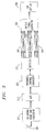
- FIG. 1 is a block diagram of a transmitter embodying the principles of the invention, illustratively in the context of a four-dimensional channel mapping scheme for HDTV;
- FIG. 2 is a block diagram of another transmitter embodying the principles of the invention in the context of a two-dimensional channel mapping scheme for HDTV, this scheme including trellis coding;
- FIG. 3 is a block diagram of a receiver for transmitted signals transmitted by the transmitter of FIG. 1; and
- FIGS. 4-11 are signal constellation maps useful in explaining the principles of the invention.
- Before proceeding with a specific description of the transmitters of FIGS. 1 and 2 and the receiver of FIG. 3, it will be helpful to first consider the theoretical underpinnings of the invention.
- First off, it should be noted that the various digital signalling concepts described herein (with the exception, of course, of the inventive concept itself) are all well known in, for example, the digital radio and voiceband data transmission (modem) arts and thus need not be described in detail herein. These include such concepts as multidimensional signalling using N-dimensional signal constellations, where N is some integer; trellis coding; scrambling; passband shaping; equalization; Viterbi, or maximum-likelihood, decoding; etc. These concepts are described in such U.S. patents as U.S. 3,810,021, issued May 7, 1974 to I. Kalet et al.; U.S. 4,015,222, issued March 29, 1977 to J. Werner; U.S. 4,170,764, issued October 9, 1979 to J. Salz et al.; U.S. 4,247,940, issued January 27, 1981 to K. H. Mueller et al.; U.S. 4,304,962, issued December 8, 1981 to R. D. Fracassi et al.; U.S. 4,457,004, issued June 26, 1984 to A. Gersho et al.; U.S. 4,489,418, issued December 18, 1984 to J. E. Mazo; U.S. 4,520,490, issued May 28, 1985 to L. Wei; and U.S. 4,597,090, issued June 24, 1986 to G. D. Forney, Jr.--all of which are hereby incorporated by reference.
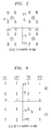
- Turning now to the drawing, FIG. 4 depicts a standard two-dimensional data transmission constellation of the type conventionally used in digital radio and voiceband data transmission systems. In this standard scheme--conventionally referred to as quadrature-amplitude modulation (QAM)--data words each comprised of four bits are each mapped into one of 16 possible two-dimensional signal points. The constellation is thus labelled "Standard 16-QAM". Each signal point has an in-phase, or I, coordinate on the horizontal axis and has a quadrature-phase, or Q, coordinate on the vertical axis. Note that, on each axis, the signal point coordinates are ± 1 or ± 3 so that the distance between each point and each of the points that are horizontally or vertically adjacent to it is the same for all points--that distance being "2".
- (The process of mapping the data words into particular signal points is referred to herein as "channel mapping" and the signal points are sometimes referred to as "channel symbols".)
- Now consider the 16-point constellation of FIG. 5, which embodies the principles of the invention. The difference between this constellation and that of FIG. 4 is the relative distance between the different signal points.
- Specifically, since the distance between all the adjacent points in FIG. 4 is the same, essentially the same probability of error is provided for all the bits which the signal points represent. (Transmission errors arise when, as the result of noise, phase jitter and various other channel phenomena/impairments, a transmitted signal point is displaced from its original position in the constellation to such an extent that it appears at the receiver that a different signal point was transmitted.) On the other hand, the distance between adjacent points in FIG. 5 is not the same for all the points. Specifically, the minimum distance between points within a particular quadrant in FIG. 5 is d = √


stream dibit 00 from those in the second quadrant representing the first-stream dibit 01--is greater than the minimum distance between the signal points representing the different values of the data elements of the second data stream--e.g., the minimum distance ( √
stream dibit 00 and the point in that same quadrant representing the second-stream dibit 01. - Assume now that two out of the four bits of each transmitted data word need more protection from error than the other two bits because they are more important than the other two bits. This is achieved in accordance with the invention by using those two, more important bits to select one of the four quadrants (as indicated by the circled dibits in FIG. 5), and using the other two bits to select one of the four points within each quadrant, as indicated by the dibits next to each point. Since the probability of not correctly identifying the quadrant of the transmitted signal point is smaller than the probability of not correctly identifying the signal point itself, the desired protection is thereby achieved.
- More generally stated, the constellation is divided into groups of signal points and each group is divided into subgroups, each of the latter being comprised of one or more signal points. At least one data element, e.g., bit, from each data word to be mapped identifies the group from which is to come the signal point that is to represent that data word, and at least one other data element identifies the subgroup within that group. If the subgroup contains more than one signal point, then further data elements are used to ultimately identify a particular one of those signal points (to which end the subgroup may be further divided into sub-subgroups). In accordance with the invention, a)the groups and subgroups are arranged such that the probability of the receiver erroneously determining which group a transmitted signal point is from is less than the probability of the receiver erroneously determining which subgroup it is from, and b) the data elements that identify the group represent information that is more important than the information represented by data elements that identify the subgroup.
- A generic version of the constellation of FIG. 5 is shown in FIG. 6 in which the coordinate values, instead of being at ± √


- Before proceeding, it is useful to make some formal definitions. As noted above, channel mapping in accordance with the invention is referred to herein as catastrophe-resistant (C-R) mapping. In general, a (n₁ , n₂ , · · ·, n k ; m ) C-R mapping will be a mapping that provides the first (best) level of protection to n₁ bits; the second level of protection to n₂ bits; and so forth. The last entry in the mapping identification is a reminder of the total number m of information bits that are transmitted, that is:

- We now briefly discuss the kind of trade-offs that are possible in the design of C-R mappings. First, we will assume that the power in the transmitted signal is subject to an average power constraint. Let a i and b i denote the I and Q discrete signal point levels, and assume that these signal points are uncorrelated. The average power constraint then requires that

for all the signal point level scenarios under consideration. Now let
denote the amount of SNR required to achieve a certain performance for the bits with the i th level of protection. The change in the amount of SNR required by these bits to achieve that level of performance compared to a standard ( m ; m ) mapping is then defined by

where SNR m is the amount of SNR required by the ( m ; m ) mapping to achieve the same performance. (This is the mapping that provides the same amount of protection to all the bits.) With the expressions in (1) and (2), we get the following relationships for the ( 2, 2 ; 4 ) mapping shown in FIG. 6:
where the incremental SNRs are expressed in dB. Using α in FIG. 6 as a parameter in (3), we can first determine the value of β and then the incremental SNRs. Some computed values are given in Table I.
- In order to give some meaning to the entries in Table I, we consider some specifics, such as the case α = √

- The trade-off that has been achieved in the previous example may seem quite brutal: On one hand, we decrease the sensitivity to noise by 3 dB for the first two bits; and then, on the other hand, we increase this sensitivity by the same 3 dB for the other two bits. Such a clean trade-off rarely happens, as should be apparent from the other entries in Table I. For example, for α = 1.2 more robustness against noise is gained by the most protected bits than is lost by the least protected bits. This is the kind of behavior to be sought in the design of efficient C-R mappings.
- The invention is not limited to two-dimensional constellations but, indeed, can be implemented with N-dimensional constellations where N ≧ 2. Indeed, an increase in the number of dimensions gives more flexibility in the design of efficient mappings. One way of implementing multidimensional C-R mappings with a QAM system is to use different two-dimensional C-R mappings in successive signal point intervals. As an example, a four-dimensional constellation can be created by concatenating all of the possible two-dimensional signal points from the ( 2, 2 ; 4 ) mapping of FIG. 5 with all of the possible two-dimensional signal points from the ( 1, 2, 1 ; 4 ) mapping of FIG. 9, as explained hereinbelow.
- It is easily shown that such a mapping procedure provides a ( 3, 2, 3 ; 8 ) four-dimensional C-R mapping. Specifically, the greatest spacing between points in the constellation of FIG. 5 is the
distance 2√

- It will thus be appreciated, by way of example, that the 8-bit word 01110100 would result in the selection of the four-dimensional signal point made up of the concatenation of point A from FIG. 5 and point A' from FIG. 9. Specifically, the first and second bits, 01, select the upper left quadrant of FIG. 5; the third bit, 1, selects the lower half of FIG. 9; the fourth and fifth bits, 10, select the second-from-right column of FIG. 9; the sixth and seventh bits, 10, select point A from the previously selected quadrant of FIG. 5; and the eighth bit, 0, selects point A' from the previously selected half and column of FIG. 9.
- For this mapping, the SNR requirements for the two bits with the second level of protection are the same as the SNR requirements for the standard QAM signal constellation in FIG. 4. The three most protected bits and the three least protected bits have the SNR requirements that were derived in the previous section for the two-dimensional ( 2, 2 ; 4 ) mapping.
- We are now in a position to consider the transmitter of FIG. 1.
-
Television signal source 101 generates an analog television signal which is passed on tosource coder 104. The latter generates a digital signal in which at least one subset of the data elements represents information that is more important than the information represented by the rest of the data elements. Two examples of how such a signal might be generated are given hereinbelow. - The source-coded signal is illustratively C-R mapped, in accordance with the invention, using the four-dimensional mapping mentioned above in which each four-dimensional signal point is comprised of a two-dimensional signal point from the constellation of FIG. 5 concatenated with a two-dimensional signal point from the constellation of FIG. 9. In accordance with a feature of the invention, it has been recognized that it is desirable to preserve the distinctness of the bits which are to be accorded a particular level of protection by the mapping, notwithstanding any processing of the bits that may be necessary prior to their being mapped into four-dimensional signal points by four-
dimensional mapper 121. Unless such distinctness is maintained, then, of course, it will not be possible to allocate the different levels of protection to the various data streams which represent the television signal. - In the present embodiment, in particular, it is desired to scramble the bits which comprise the digital signal in order to ensure a relatively uniform distribution of energy across the frequency band that the signal takes up. Accordingly, those bits are scrambled in three separate groups. Bits b₁, b₂ and b₃, which contain the most important information and are therefore to be accorded the highest level of protection, are scrambled by a
first scrambler 111; bits b₄ and b₅, which contain the second-most-important information and are therefore to be accorded the second-highest level of protection, are scrambled by asecond scrambler 112; and bits b₆, b₇ and b₈, which contain the least important amount of information and are therefore to be accorded the lowest level of protection, are scrambled by athird scrambler 113. (Scrambling is customarily carried out on a serial bit stream. Thus although not explicitly shown in FIG. 1,scramblers - The eight scrambled bits are applied in parallel in a four-
dimensional mapper 121, mentioned above, which identifies a four-dimensional signal point to be generated using, for example, the bit-assignment scheme described above.Mapper 121 may be, for example, realized using table look-up. Conventional passband shaping and television modulation are then performed bypassband shaper 141 andtelevision modulator 151, respectively. The resultant analog television signal is then broadcast viaantenna 152. - Turning now to the receiver of FIG. 3, the analog television signal is received by
antenna 301, is subjected to conventional television front-end processing including, for example, demodulation inprocessing unit 311, and is converted to digital form by A/D converter 312. The signal is then equalized bypassband channel equalizer 321 and passed on todetector 331. The latter stores information relating to the mapping--specifically, information indicative of the positions of the signal points of the constellation and the manner in which they are divided into groups and subgroups--and performs a so-called "slicing" operation on the equalized signal in order to form decisions as to what the transmitted signal points were in response to the stored information. Apart from having knowledge about the way in which the constellations of FIGS. 5 and 9 are configured pursuant to the invention, the detector is otherwise standard. - The 8-bit words output by
detector 331 are descrambled bydescramblers scramblers picture signal generator 353. That signal is then applied toCRT display 360. - One more step of sophistication in the design of efficient C-R mappings can be achieved by adding redundancy to the signal constellations. Adding redundancy allows the usage of forward-error-correction coding, such as trellis coding. One of the issues with trellis coding is that its effect on the error rate of individual bits is not well understood. The published studies seem to have concentrated on the probability of error events, which is not easily related to the bit-error rate for trellis-coded systems. Nevertheless, even a simple example can show how more powerful C-R mappings can be obtained by using trellis coding.
- Assume that we want to transmit three bits per signal point, and that one of the bits requires much more protection than the other bits. For a non-trellis-coded system, this can be done by using a ( 1, 2 ; 3 ) C-R mapping that has the signal constellation shown in FIG. 10. The most important bit defines the upper or lower half plane, and the other two bits define one of four possible points in each half plane. It is easily verified that the most valuable bit has 7 dB more margin against noise than the other two bits. We now assume that independent one-dimensional trellis codes are used along each axis in FIG. 10, thereby, in practical effect, increasing the distance between the rows and, independently, the distance between the points within a row. This leads to the signal constellation shown in FIG. 11. Specifically, one of the three bits is trellis-coded to become two bits which select one of the four rows in FIG. 11, and the other two bits are trellis-coded independently of the first bit to become three bits which select one of the eight columns in FIG. 11.
- FIG. 2 shows a block diagram of a transmitter utilizing the constellation of FIG. 11.
Television signal source 201 generates an analog television signal which is passed on tosource coder 204. The latter generates a digital signal comprised of 3-bit binary data words c₁, c₂, c₃, in which it is assumed that bit c₁ is more important than the the other two bits c₂ and c₃. Bit c₁ is scrambled by afirst scrambler 211, while bits c₂ and c₃ are scrambled by asecond scrambler 212. - The output of
scrambler 211 is trellis-encoded by quadrature-phase trellis coder 215, while the output ofscrambler 212 is trellis-encoded by in-phase trellis coder 216. The 2-bit output oftrellis coder 215 identifies one of the four rows of the FIG. 11 constellation, as described above. Those two bits are applied to quadrature-phase one-dimensional mapper 221, which generates an output identifying one of the four y-axis coordinates ± 1, ± 3. At the same time, the 3-bit output oftrellis coder 216 identifies one of the eight columns of the FIG. 11 constellation. Those three bits are applied to in-phase one-dimensional mapper 222, which generates an output identifying one of the eight x-axis coordinates ± 0.5, ± 1.5, ± 2.5 and ± 3.5. Conventional passband shaping is then performed by quadrature-phase passband shaper 241 and in-phase passband shaper 242, whose outputs are combined in anadder 243. The resulting combined signal is then applied totelevision modulator 251, whose output analog signal is broadcast viaantenna 252. - A specific receiver for the signal generated by the transmitter of FIG. 2 is not shown. Those skilled in the art will, however, be readily able to design such a receiver using standard building blocks similar to those used in FIG. 3, although in this case the detector stage preferably includes a maximum likelihood, or Viterbi, decoder in order to take advantage of the coding gain afforded by the trellis codes.
- With this kind of trellis coding, we can decrease the sensitivity to noise by 3 dB for all the bits. For a probability of error of 10⁻⁶, the most important bit then requires an SNR of about 11 dB, and the other two bits require an SNR of about 18 dB. (For simplicity, we assume here that the channel has a flat amplitude response.) If standard 8-point uncoded and 16-point trellis-coded signal constellations were utilized instead, the SNR requirements would be 18 dB and 15 dB, respectively, for the same error rate. Designs for trellis-coded C-R mappings that are directly carried out in a multidimensional space should be even more powerful.
- The foregoing merely illustrates the principles of the invention. For example, the invention is illustrated herein in the context of a digital TV transmission system. However, it is equally applicable to other types of digital transmission systems. Moreover, although particular constellations are shown herein, numerous other constellations, which may be of any desired dimensionality, can be used. For example, the various constituent two-dimensional C-R mappings that are used to provide higher-dimensional, e.g., four-dimensional, mappings may be used in unequal proportions. Alternatively, signal constellations with a different number of points may also be used in successive signal point intervals. All these possibilities provide a great flexibility for the design of efficient multidimensional C-R mappings. Additionally, it should be pointed out that four dimensions are naturally available in HDTV applications because of the possibility of using horizontal and vertical polarizations at the same time. Theoretically, this allows the simultaneous transmission of two independent QAM signals. Thus, for this application, there is an opportunity to implement multidimensional C-R mappings both in time (over different signal point periods) and in space (between polarizations).
- Additionally, although a particular type of source coding is used in the illustrative embodiment hereof, it is envisioned that various other approaches to the digital representation of the television signal, i.e., other types of source coding, can be employed in order to give more protection to some of the transmitted bits. Such approaches might include the use of, for example, trellis/convolutional codes, BCH codes, Reed-Solomon codes, and/or concatenations of same. Disadvantageously, some channel mapping schemes may expand the bandwidth of the transmitted signal or may have potential synchronisation problems, and may not be cost effective. In any case, if these problems can be resolved, the present invention can always be combined with any such approachs since the latter operate on the bit stream. Also, it is envisioned that the source coding may well include other types of processing, such as any of various forms of television signal compression.
- It may also be noted that although the invention is illustrated herein as being implemented with discrete functional building blocks, e.g., source coders, scramblers, etc., the functions of any one or more of those building blocks can be carried out using one or more appropriate programmed processors, digital signal processing (DSP) chips, etc.
- It will thus be appreciated that those skilled in the art will be able to devise numerous and various alternative arrangements which, although not explicitly shown or described herein, embody the principles of the invention and are within its spirit and scope.
Claims (24)
- A method for communicating information
CHARACTERIZED BY
the steps of
generating a digital signal representing the information, the digital signal being comprised of at least first and second data streams of data elements,
channel mapping the digital signal, and
transmitting the mapped signal over a communication channel,
the mapping step being such that the probability of channel-induced error for the data elements of the first data stream is less than the probability of channel-induced error for the data elements of the second data stream. - The invention of claim 1
CHARACTERIZED IN THAT
said information is television signal information. - The invention of claim 1
CHARACTERIZED IN THAT
said mapping step includes the step of trellis coding the digital signal. - The invention of claim 1
CHARACTERIZED IN THAT
said generating step includes the steps of receiving the information, and
source coding the information using a predetermined source code. - The invention of claim 1
CHARACTERIZED IN THAT
the mapping step comprises the step of
selecting a sequence of signal points from a predefined constellation of signal points to represent the data elements, the constellation being such that the minimum distance between signal points representing different values of the data elements of said first data stream is greater than the minimum distance between signal points representing the different values of the data elements of said second data stream. - The invention of claim 5
CHARACTERIZED IN THAT
said constellation is an N-dimensional constellation, where N ≧ 2. - The invention of claim 5
CHARACTERIZED IN THAT
said generating step includes the steps of receiving the information, and
source coding the information using a predetermined source code. - The invention of claim 7
CHARACTERIZED IN THAT
said generating step includes the further step of processing the source-coded information using at least a first predetermined processing algorithm, said processing being carried out for the data elements of said first data stream independently of the processing carried out for the data elements of said second data stream. - Apparatus for use in a digital transmission system of the type in which signal points from a predetermined signal point constellation representing respective associated data words are communicated from said transmitter over a communication channel to a receiver, said data words being comprised of individual data elements, said constellation being divided into groups of signal points and each of said groups being divided into subgroups of signal points, said apparatus including
means responsive to at least one of the data elements of each said data word for identifying which particular one of said groups includes the signal point associated with said data word and responsive to at least one other of the data elements of that word for identifying which particular one of the subgroups within said particular group includes the signal point associated with said data word, and
means for generating a signal representing a signal point from the identified subgroup and for applying that signal to said communication channel,
CHARACTERIZED IN THAT
said groups and subgroups are arranged such that the probability of said receiver erroneously determining which group a transmitted signal point is from is less than the probability of said receiver erroneously determining which subgroup it is from. - The invention of claim 9
FURTHER CHARACTERIZED IN THAT
the data elements that identify said particular group represent more important information than the data elements that identify said particular subgroup. - The invention of claim 9
CHARACTERIZED IN THAT
said information is television signal information. - The invention of claim 9
CHARACTERIZED IN THAT
said data words are trellis encoded data words. - The invention of claim 9
CHARACTERIZED IN THAT
said constellation is an N-dimensional constellation, where N ≧ 2. - An arrangement for use in a receiver which receives intelligence communicated to said receiver by a transmitter, said transmitter including apparatus for a) generating a digital signal representing the intelligence, the digital signal being comprised of at least first and second data streams of data elements; b) channel mapping the digital signal using a predetermined signal constellation; and c) transmitting the mapped signal over a communication channel to the receiver, said mapping being such that the probability of channel-induced error for the data elements of the first data stream is less than the probability of channel-induced error for the data elements of the second data stream, said arrangement
CHARACTERIZED BY
means for receiving the transmitted signal, and
means for storing information relating to said signal constellation and for recovering said intelligence from the received signal in response to said stored information. - The invention of claim 14
CHARACTERIZED IN THAT
said intelligence is television signal information. - The invention of claim 15
CHARACTERIZED IN THAT
said mapping includes trellis coding of the digital signal and
FURTHER CHARACTERIZED IN THAT
said recovering means includes a maximum-likelihood decoder. - The invention of claim 14
CHARACTERIZED IN THAT
said mapping includes the selecting of a sequence of signal points from a predefined constellation of signal points to represent the data elements and
FURTHER CHARACTERIZED IN THAT
said stored information is indicative of the positions of the signal points of said constellation. - The invention of claim 17
CHARACTERIZED IN THAT
said constellation is an N-dimensional constellation, where N ≧ 2. - The invention of claim 14 CHARACTERIZED IN THAT
said mapping includes the selecting of a sequence of signal points from a predefined constellation of signal points to represent the data elements, the constellation being such that the minimum distance between signal points representing different values of the data elements of said first data stream is greater than the minimum distance between signal points representing the different values of the data elements of said second data stream, and
FURTHER CHARACTERIZED IN THAT
the stored information is indicative of the positions of the signal points of said constellation. - A method for use in a receiver of a digital transmission system, said system being of a type in which signal points selected from a predetermined signal point constellation to represent respective associated data words are communicated from said transmitter over a communication channel to a receiver, said data words being comprised of individual data elements, said constellation being divided into groups of signal points and each of said groups being divided into subgroups of signal points, and said signal points being selected by following the steps ofa) identifying, in response to at least one of the data elements of each said data word, which particular one of said groups includes the signal point associated with said data word and, in response to at least one other of the data elements of that word, which particular one of the subgroups within said particular group includes the signal point associated with said data word, andb) generating a signal representing a signal point from the identified subgroup and applying that signal to said communication channel, said groups and subgroups being arranged such that the probability of said receiver erroneously determining which group a transmitted signal point is from is less than the probability of said receiver erroneously determining which subgroup it is from,said method
CHARACTERIZED BY
the steps of
receiving the transmitted signal points, and
recovering from the received signal points the data words represented thereby, said recovering being carried out in response to information stored, in said receiver, about said constellation and the manner in which it is divided into said groups and subgroups. - The invention of claim 20
FURTHER CHARACTERIZED IN THAT
the data elements that are used to identify said particular group represent more important intelligence than the data elements that identify said particular subgroup. - The invention of claim 20
CHARACTERIZED IN THAT
said information is television signal information. - The invention of claim 20
CHARACTERIZED IN THAT
said data words are trellis encoded data words. - The invention of claim 20
CHARACTERIZED IN THAT
said constellation is an N-dimensional constellation, where N ≧ 2.
Applications Claiming Priority (2)
| Application Number | Priority Date | Filing Date | Title |
|---|---|---|---|
| US611225 | 1984-05-17 | ||
| US07/611,225 US5164963A (en) | 1990-11-07 | 1990-11-07 | Coding for digital transmission |
Publications (3)
| Publication Number | Publication Date |
|---|---|
| EP0485105A2 true EP0485105A2 (en) | 1992-05-13 |
| EP0485105A3 EP0485105A3 (en) | 1992-09-30 |
| EP0485105B1 EP0485105B1 (en) | 1997-01-02 |
Family
ID=24448144
Family Applications (1)
| Application Number | Title | Priority Date | Filing Date |
|---|---|---|---|
| EP91310009A Expired - Lifetime EP0485105B1 (en) | 1990-11-07 | 1991-10-30 | Coding for digital transmission |
Country Status (7)
| Country | Link |
|---|---|
| US (2) | US5164963A (en) |
| EP (1) | EP0485105B1 (en) |
| JP (1) | JP2665092B2 (en) |
| KR (1) | KR950011198B1 (en) |
| DE (1) | DE69123948T2 (en) |
| HK (1) | HK42697A (en) |
| SG (1) | SG43761A1 (en) |
Cited By (23)
| Publication number | Priority date | Publication date | Assignee | Title |
|---|---|---|---|---|
| EP0506400A2 (en) * | 1991-03-27 | 1992-09-30 | Matsushita Electric Industrial Co., Ltd. | Signal transmission system |
| EP0540231A2 (en) * | 1991-10-31 | 1993-05-05 | AT&T Corp. | Coded modulation with unequal error protection |
| EP0540232A2 (en) * | 1991-10-31 | 1993-05-05 | AT&T Corp. | Coded modulation with unequal error protection |
| EP0562875A1 (en) * | 1992-03-26 | 1993-09-29 | Matsushita Electric Industrial Co., Ltd. | Multiresolution QAM system |
| US5289501A (en) * | 1991-11-26 | 1994-02-22 | At&T Bell Laboratories | Coded modulation with unequal error protection for fading channels |
| EP0589709A2 (en) * | 1992-09-25 | 1994-03-30 | Matsushita Electric Industrial Co., Ltd. | Multiresolution transmission system |
| EP0594505A1 (en) * | 1992-10-22 | 1994-04-27 | France Telecom | Method for hierarchical coding/decoding of a digital signal and corresponding system used for digital television |
| EP0609017A2 (en) * | 1993-01-29 | 1994-08-03 | AT&T Corp. | Scheme for transmitting encoded blocks of video signals at different channel rates |
| EP0616454A1 (en) * | 1993-03-17 | 1994-09-21 | Laboratoires D'electronique Philips S.A.S. | Multi-resolution digital transmission system |
| EP0617531A1 (en) * | 1993-03-25 | 1994-09-28 | Matsushita Electric Industrial Co., Ltd. | Multiresolution transmission system |
| EP0624033A2 (en) * | 1993-05-07 | 1994-11-09 | Koninklijke Philips Electronics N.V. | QAM television transmission system |
| EP0632661A1 (en) * | 1993-06-30 | 1995-01-04 | Laboratoires D'electronique Philips S.A.S. | System for receiving and decoding digital signals according to two image definition levels |
| US5802241A (en) * | 1992-03-26 | 1998-09-01 | Matsushita Electric Industrial Co., Ltd. | Communication system |
| EP0869674A1 (en) * | 1997-04-04 | 1998-10-07 | Harris Corporation | Transmitting system and method |
| US5892879A (en) * | 1992-03-26 | 1999-04-06 | Matsushita Electric Industrial Co., Ltd. | Communication system for plural data streams |
| GB2378869A (en) * | 2001-06-09 | 2003-02-19 | Samsung Electronics Co Ltd | Rearranging codeword sequences for prioritising the mapping of bits |
| EP1387540A2 (en) | 2002-03-06 | 2004-02-04 | Nokia Corporation | Method and apparatus for modulation, using a constellation of at least dimensions |
| USRE38483E1 (en) | 1992-03-26 | 2004-03-30 | Matsushita Electric Industrial Co., Ltd. | Communication system |
| US6724976B2 (en) | 1992-03-26 | 2004-04-20 | Matsushita Electric Industrial Co., Ltd. | Communication system |
| US6728467B2 (en) | 1992-03-26 | 2004-04-27 | Matsushita Electric Industrial Co., Ltd. | Communication system |
| USRE39928E1 (en) | 1991-03-27 | 2007-11-27 | Matsushita Electric Industrial Co., Ltd. | Communication system |
| USRE40242E1 (en) | 1991-03-27 | 2008-04-15 | Matsushita Electric Industrial Co., Ltd. | Communication system |
| CN102131104A (en) * | 2011-03-22 | 2011-07-20 | 中广传播集团有限公司 | Method for scrambling service |
Families Citing this family (78)
| Publication number | Priority date | Publication date | Assignee | Title |
|---|---|---|---|---|
| US5285276A (en) * | 1991-03-12 | 1994-02-08 | Zenith Electronics Corp. | Bi-rate high definition television signal transmission system |
| US5600672A (en) | 1991-03-27 | 1997-02-04 | Matsushita Electric Industrial Co., Ltd. | Communication system |
| USRE42643E1 (en) | 1991-03-27 | 2011-08-23 | Panasonic Corporation | Communication system |
| US6487362B1 (en) | 1991-08-19 | 2002-11-26 | Index Systems, Inc. | Enhancing operations of video tape cassette players |
| US6091884A (en) * | 1991-08-19 | 2000-07-18 | Index Systems, Inc. | Enhancing operations of video tape cassette players |
| DE4135070C1 (en) * | 1991-10-24 | 1993-05-19 | Institut Fuer Rundfunktechnik Gmbh, 8000 Muenchen, De | |
| US5243419A (en) * | 1991-10-31 | 1993-09-07 | At&T Bell Laboratories | Soft coding for HDTV |
| DE69332849T2 (en) | 1992-01-14 | 2003-12-18 | Fujitsu Ltd | Simultaneous transmission of data and analogue voice band signals |
| US7158577B1 (en) | 1992-03-26 | 2007-01-02 | Matsushita Electric Industrial Co., Ltd. | Communication system |
| US7894541B2 (en) * | 1992-03-26 | 2011-02-22 | Panasonic Corporation | Communication system |
| US5282226A (en) * | 1992-04-27 | 1994-01-25 | Hughes Aircraft Company | System and method for transmission of bursts of digital information |
| US5311553A (en) * | 1992-06-15 | 1994-05-10 | General Electric Company | Trellis coding technique to increase adjacent channel interference protection ratio in land mobile radio systems under peak power constraints |
| US5311552A (en) * | 1992-06-15 | 1994-05-10 | General Electric Company | Trellis coding technique to improve adjacent channel interference protection ratio in land mobile radio systems |
| US5289276A (en) * | 1992-06-19 | 1994-02-22 | General Electric Company | Method and apparatus for conveying compressed video data over a noisy communication channel |
| US5331348A (en) * | 1992-07-27 | 1994-07-19 | At&T Bell Laboratories | Adaptive leak HDTV encoder |
| US5438369A (en) * | 1992-08-17 | 1995-08-01 | Zenith Electronics Corporation | Digital data interleaving system with improved error correctability for vertically correlated interference |
| US5565926A (en) * | 1993-05-07 | 1996-10-15 | Philips Electronics North America Corporation | Method and apparatus for communicating digital television signals using a signal constellation formed by four signal constellations placed in the quadrants |
| KR950002458A (en) * | 1993-06-02 | 1995-01-04 | 이헌조 | Video signal compression / extension device |
| US5440585A (en) * | 1993-06-14 | 1995-08-08 | At&T Corp. | Applications of simultaneous analog and digital communication |
| US5376969A (en) * | 1993-11-15 | 1994-12-27 | Rca Thomson Licensing Corporation | Method and apparatus for conveying compressed video data over a noisy communication channel |
| US5452009A (en) * | 1993-12-29 | 1995-09-19 | Zenith Electronics Corp. | Digital transmission system with data rate optimized for noise in transmission medium |
| TW249873B (en) * | 1994-03-21 | 1995-06-21 | At & T Corp | Time division multiplexing data communication arrangement with different signal constellation |
| US5398073A (en) * | 1994-04-12 | 1995-03-14 | At&T Corp. | Concatenated coded vestigial sideband modulation for high definition television |
| US5465273A (en) * | 1994-04-20 | 1995-11-07 | General Datacomm, Inc. | Modem utilizing parity and convolutional encoder feedback |
| US5583889A (en) * | 1994-07-08 | 1996-12-10 | Zenith Electronics Corporation | Trellis coded modulation system for HDTV |
| US5617541A (en) * | 1994-12-21 | 1997-04-01 | International Computer Science Institute | System for packetizing data encoded corresponding to priority levels where reconstructed data corresponds to fractionalized priority level and received fractionalized packets |
| US5570391A (en) * | 1995-03-06 | 1996-10-29 | Chung-Chin Chen | Trellis coding method using a multilevel delay device |
| JP3170193B2 (en) * | 1995-03-16 | 2001-05-28 | 松下電器産業株式会社 | Image signal encoding apparatus and decoding apparatus |
| US5621762A (en) * | 1995-06-12 | 1997-04-15 | Motorola, Inc. | Radio with peak power and bandwidth efficient modulation |
| US6049572A (en) * | 1996-12-30 | 2000-04-11 | Intel Corporation | Optimization of QAM constellation space for auxiliary I-Q signaling |
| US6043844A (en) * | 1997-02-18 | 2000-03-28 | Conexant Systems, Inc. | Perceptually motivated trellis based rate control method and apparatus for low bit rate video coding |
| US6167085A (en) * | 1997-07-31 | 2000-12-26 | Sony Corporation | Image data compression |
| US6031874A (en) * | 1997-09-26 | 2000-02-29 | Ericsson Inc. | Unequal error protection in coded modulation schemes |
| US6307487B1 (en) | 1998-09-23 | 2001-10-23 | Digital Fountain, Inc. | Information additive code generator and decoder for communication systems |
| US7068729B2 (en) | 2001-12-21 | 2006-06-27 | Digital Fountain, Inc. | Multi-stage code generator and decoder for communication systems |
| US6603809B1 (en) * | 1999-12-29 | 2003-08-05 | Nokia Corporation | Apparatus, and associated method, for forming a signal for communication upon a fading channel |
| JP3506330B2 (en) | 2000-12-27 | 2004-03-15 | 松下電器産業株式会社 | Data transmission device |
| US7693179B2 (en) * | 2002-11-29 | 2010-04-06 | Panasonic Corporation | Data transmission apparatus using a constellation rearrangement |
| BR0110161A (en) * | 2001-02-21 | 2002-12-31 | Matsushita Electric Ind Co Ltd | Hybrid file method with redisposition of signal constellation |
| US20060203927A1 (en) | 2001-03-27 | 2006-09-14 | Aware, Inc. | Systems and methods for implementing receiver transparent Q-mode |
| KR100539862B1 (en) | 2001-04-04 | 2005-12-28 | 삼성전자주식회사 | Method and apparatus for transporting and receiving data in cdma mobile system |
| DE60113128T2 (en) | 2001-11-16 | 2006-03-02 | Matsushita Electric Industrial Co., Ltd., Kadoma | Hybrid ARQ method for data packet transmission |
| EP1313247B1 (en) * | 2001-11-16 | 2005-11-09 | Matsushita Electric Industrial Co., Ltd. | Incremental redundancy ARQ retransmission method using bit reordering schemes |
| KR20030049302A (en) * | 2001-12-14 | 2003-06-25 | 한국전자통신연구원 | Frequency modulation method to use base-band encoding apparatus in digital broadcasting system |
| JP3815344B2 (en) * | 2002-02-21 | 2006-08-30 | 株式会社日立製作所 | Codeword mapping method suitable for multilevel modulation |
| US9240810B2 (en) | 2002-06-11 | 2016-01-19 | Digital Fountain, Inc. | Systems and processes for decoding chain reaction codes through inactivation |
| EP2348640B1 (en) | 2002-10-05 | 2020-07-15 | QUALCOMM Incorporated | Systematic encoding of chain reaction codes |
| KR101170629B1 (en) | 2003-10-06 | 2012-08-02 | 디지털 파운튼, 인크. | Error-correcting multi-stage code generator and decoder for communication systems having single transmitters or multiple transmitters |
| EP1706946A4 (en) * | 2003-12-01 | 2006-10-18 | Digital Fountain Inc | Protection of data from erasures using subsymbol based codes |
| EP1743431A4 (en) | 2004-05-07 | 2007-05-02 | Digital Fountain Inc | File download and streaming system |
| KR100714973B1 (en) * | 2004-08-16 | 2007-05-04 | 삼성전자주식회사 | Apparatus and method for changing signal point mapping rule in harq system |
| JP2008532192A (en) * | 2004-11-08 | 2008-08-14 | コーニンクレッカ フィリップス エレクトロニクス エヌ ヴィ | Bit detection in multitrack digital data storage |
| CN101686107B (en) | 2006-02-13 | 2014-08-13 | 数字方敦股份有限公司 | Streaming and buffering using variable FEC overhead and protection periods |
| US9270414B2 (en) * | 2006-02-21 | 2016-02-23 | Digital Fountain, Inc. | Multiple-field based code generator and decoder for communications systems |
| WO2007100184A1 (en) * | 2006-02-28 | 2007-09-07 | Lg Electronics Inc. | Digital broadcasting system and method of processing data |
| WO2007134196A2 (en) | 2006-05-10 | 2007-11-22 | Digital Fountain, Inc. | Code generator and decoder using hybrid codes |
| US9386064B2 (en) | 2006-06-09 | 2016-07-05 | Qualcomm Incorporated | Enhanced block-request streaming using URL templates and construction rules |
| US9380096B2 (en) | 2006-06-09 | 2016-06-28 | Qualcomm Incorporated | Enhanced block-request streaming system for handling low-latency streaming |
| US9178535B2 (en) | 2006-06-09 | 2015-11-03 | Digital Fountain, Inc. | Dynamic stream interleaving and sub-stream based delivery |
| US9432433B2 (en) | 2006-06-09 | 2016-08-30 | Qualcomm Incorporated | Enhanced block-request streaming system using signaling or block creation |
| US9419749B2 (en) | 2009-08-19 | 2016-08-16 | Qualcomm Incorporated | Methods and apparatus employing FEC codes with permanent inactivation of symbols for encoding and decoding processes |
| US9209934B2 (en) | 2006-06-09 | 2015-12-08 | Qualcomm Incorporated | Enhanced block-request streaming using cooperative parallel HTTP and forward error correction |
| US20080205229A1 (en) * | 2007-02-26 | 2008-08-28 | Yung-Chih Li | Method of identifying optical disc |
| US9237101B2 (en) | 2007-09-12 | 2016-01-12 | Digital Fountain, Inc. | Generating and communicating source identification information to enable reliable communications |
| US9281847B2 (en) | 2009-02-27 | 2016-03-08 | Qualcomm Incorporated | Mobile reception of digital video broadcasting—terrestrial services |
| US9288010B2 (en) | 2009-08-19 | 2016-03-15 | Qualcomm Incorporated | Universal file delivery methods for providing unequal error protection and bundled file delivery services |
| US9917874B2 (en) | 2009-09-22 | 2018-03-13 | Qualcomm Incorporated | Enhanced block-request streaming using block partitioning or request controls for improved client-side handling |
| US9225961B2 (en) | 2010-05-13 | 2015-12-29 | Qualcomm Incorporated | Frame packing for asymmetric stereo video |
| US9596447B2 (en) | 2010-07-21 | 2017-03-14 | Qualcomm Incorporated | Providing frame packing type information for video coding |
| US8806050B2 (en) | 2010-08-10 | 2014-08-12 | Qualcomm Incorporated | Manifest file updates for network streaming of coded multimedia data |
| US9270299B2 (en) | 2011-02-11 | 2016-02-23 | Qualcomm Incorporated | Encoding and decoding using elastic codes with flexible source block mapping |
| US8958375B2 (en) | 2011-02-11 | 2015-02-17 | Qualcomm Incorporated | Framing for an improved radio link protocol including FEC |
| US9253233B2 (en) | 2011-08-31 | 2016-02-02 | Qualcomm Incorporated | Switch signaling methods providing improved switching between representations for adaptive HTTP streaming |
| US9843844B2 (en) | 2011-10-05 | 2017-12-12 | Qualcomm Incorporated | Network streaming of media data |
| US9047203B1 (en) * | 2011-12-21 | 2015-06-02 | Altera Corporation | Systems and methods for encoding and decoding data |
| US9294226B2 (en) | 2012-03-26 | 2016-03-22 | Qualcomm Incorporated | Universal object delivery and template-based file delivery |
| KR20140048004A (en) * | 2012-10-15 | 2014-04-23 | 콘티넨탈 오토모티브 시스템 주식회사 | Method and apparatus for controlling shift quality of hybrid vehicle |
| US10153935B2 (en) * | 2016-07-18 | 2018-12-11 | Intel Corporation | Apparatus, system and method of communicating a transmission according to a rotated 256 quadrature amplitude modulation (QAM) scheme |
Citations (7)
| Publication number | Priority date | Publication date | Assignee | Title |
|---|---|---|---|---|
| US4015222A (en) | 1975-12-01 | 1977-03-29 | Bell Telephone Laboratories, Incorporated | Modulated passband signal generator |
| US4247940A (en) | 1979-10-15 | 1981-01-27 | Bell Telephone Laboratories, Incorporated | Equalizer for complex data signals |
| US4457004A (en) | 1982-02-08 | 1984-06-26 | Bell Telephone Laboratories, Incorporated | Multidimensional channel coding |
| US4489418A (en) | 1983-04-18 | 1984-12-18 | At&T Bell Laboratories | Differential encoding technique |
| US4520490A (en) | 1983-08-05 | 1985-05-28 | At&T Information Systems Inc. | Differentially nonlinear convolutional channel coding with expanded set of signalling alphabets |
| US4597090A (en) | 1983-04-14 | 1986-06-24 | Codex Corporation | Block coded modulation system |
| EP0282298A2 (en) | 1987-03-13 | 1988-09-14 | Space Systems / Loral, Inc. | Method and apparatus for combining encoding and modulation |
Family Cites Families (16)
| Publication number | Priority date | Publication date | Assignee | Title |
|---|---|---|---|---|
| US3909721A (en) * | 1972-01-31 | 1975-09-30 | Signatron | Signal processing system |
| US4346473A (en) * | 1980-02-26 | 1982-08-24 | Harris Corporation | Error correction coding method and apparatus for multilevel signaling |
| US4644537A (en) * | 1984-12-24 | 1987-02-17 | American Telephone And Telegraph Company | Inband coding of secondary data |
| US4651320A (en) * | 1984-12-24 | 1987-03-17 | American Telephone And Telegraph Company | Inband coding of secondary data |
| US4823346A (en) * | 1986-04-16 | 1989-04-18 | Hitachi, Ltd. | Maximum likelihood decoder |
| AU621536B2 (en) * | 1987-02-24 | 1992-03-19 | General Electric Capital Corporation | Partial response channel signaling systems |
| CA1274929A (en) * | 1987-08-06 | 1990-10-02 | John Duncan Mcnicol | Method of communicating stuffing indications in a multi-level communications system |
| US4891806A (en) * | 1987-09-18 | 1990-01-02 | Racal Data Communications Inc. | Constellation multiplexed inband secondary channel for voiceband modem |
| US4924492A (en) * | 1988-03-22 | 1990-05-08 | American Telephone And Telegraph Company | Method and apparatus for wideband transmission of digital signals between, for example, a telephone central office and customer premises |
| US4980897A (en) * | 1988-08-12 | 1990-12-25 | Telebit Corporation | Multi-channel trellis encoder/decoder |
| US4901331A (en) * | 1989-05-19 | 1990-02-13 | American Telephone And Telegraph Company | Trellis codes with passband spectral nulls |
| US5128758A (en) * | 1989-06-02 | 1992-07-07 | North American Philips Corporation | Method and apparatus for digitally processing a high definition television augmentation signal |
| US5140417A (en) * | 1989-06-20 | 1992-08-18 | Matsushita Electric Co., Ltd. | Fast packet transmission system of video data |
| GB8929152D0 (en) * | 1989-12-22 | 1990-02-28 | Gen Electric | A digital augmentation system for actv-ii |
| US5148274A (en) * | 1990-03-19 | 1992-09-15 | At&T Bell Laboratories | PAM signals modulation with mappings to improve utilization of available transmission capacity |
| US5159453A (en) * | 1990-09-07 | 1992-10-27 | New York Institute Of Technology | Video processing method and apparatus |
-
1990
- 1990-11-07 US US07/611,225 patent/US5164963A/en not_active Expired - Lifetime
-
1991
- 1991-10-23 JP JP3302629A patent/JP2665092B2/en not_active Expired - Lifetime
- 1991-10-30 SG SG1996000660A patent/SG43761A1/en unknown
- 1991-10-30 EP EP91310009A patent/EP0485105B1/en not_active Expired - Lifetime
- 1991-10-30 DE DE69123948T patent/DE69123948T2/en not_active Expired - Lifetime
- 1991-11-01 KR KR1019910019377A patent/KR950011198B1/en not_active IP Right Cessation
-
1992
- 1992-11-16 US US07/976,625 patent/US5524025A/en not_active Expired - Lifetime
-
1997
- 1997-04-03 HK HK42697A patent/HK42697A/en not_active IP Right Cessation
Patent Citations (7)
| Publication number | Priority date | Publication date | Assignee | Title |
|---|---|---|---|---|
| US4015222A (en) | 1975-12-01 | 1977-03-29 | Bell Telephone Laboratories, Incorporated | Modulated passband signal generator |
| US4247940A (en) | 1979-10-15 | 1981-01-27 | Bell Telephone Laboratories, Incorporated | Equalizer for complex data signals |
| US4457004A (en) | 1982-02-08 | 1984-06-26 | Bell Telephone Laboratories, Incorporated | Multidimensional channel coding |
| US4597090A (en) | 1983-04-14 | 1986-06-24 | Codex Corporation | Block coded modulation system |
| US4489418A (en) | 1983-04-18 | 1984-12-18 | At&T Bell Laboratories | Differential encoding technique |
| US4520490A (en) | 1983-08-05 | 1985-05-28 | At&T Information Systems Inc. | Differentially nonlinear convolutional channel coding with expanded set of signalling alphabets |
| EP0282298A2 (en) | 1987-03-13 | 1988-09-14 | Space Systems / Loral, Inc. | Method and apparatus for combining encoding and modulation |
Cited By (57)
| Publication number | Priority date | Publication date | Assignee | Title |
|---|---|---|---|---|
| EP0975170A1 (en) * | 1991-03-27 | 2000-01-26 | Matsushita Electric Industrial Co., Ltd. | Signal transmission system |
| EP0766478A3 (en) * | 1991-03-27 | 2000-01-19 | Matsushita Electric Industrial Co., Ltd. | Signal transmission system |
| EP1359761A3 (en) * | 1991-03-27 | 2006-01-18 | Matsushita Electric Industrial Co., Ltd. | Signal transmission system |
| EP0506400A3 (en) * | 1991-03-27 | 1993-05-26 | Matsushita Electric Industrial Co., Ltd. | Signal transmission system |
| EP0506400A2 (en) * | 1991-03-27 | 1992-09-30 | Matsushita Electric Industrial Co., Ltd. | Signal transmission system |
| EP0975168A1 (en) * | 1991-03-27 | 2000-01-26 | Matsushita Electric Industrial Co., Ltd. | Signal transmission system |
| USRE40242E1 (en) | 1991-03-27 | 2008-04-15 | Matsushita Electric Industrial Co., Ltd. | Communication system |
| US5555275A (en) * | 1991-03-27 | 1996-09-10 | Matsushita Electric Industrial Co., Ltd. | Multi-threshold and hierarchical television signal transmission system |
| USRE39928E1 (en) | 1991-03-27 | 2007-11-27 | Matsushita Electric Industrial Co., Ltd. | Communication system |
| EP1359761A2 (en) * | 1991-03-27 | 2003-11-05 | Matsushita Electric Industrial Co., Ltd. | Signal transmission system |
| EP0975169A1 (en) * | 1991-03-27 | 2000-01-26 | Matsushita Electric Industrial Co., Ltd. | Signal transmission system |
| EP0975173A1 (en) * | 1991-03-27 | 2000-01-26 | Matsushita Electric Industrial Co., Ltd. | Signal transmission system |
| EP0975174A1 (en) * | 1991-03-27 | 2000-01-26 | Matsushita Electric Industrial Co., Ltd. | Signal transmission system |
| EP1049334A1 (en) * | 1991-03-27 | 2000-11-02 | Matsushita Electric Industrial Co., Ltd. | Signal transmission system |
| EP0975171A1 (en) * | 1991-03-27 | 2000-01-26 | Matsushita Electric Industrial Co., Ltd. | Signal transmission system |
| EP0973335A1 (en) * | 1991-03-27 | 2000-01-19 | Matsushita Electric Industrial Co., Ltd. | Signal transmission system |
| EP0975172A1 (en) * | 1991-03-27 | 2000-01-26 | Matsushita Electric Industrial Co., Ltd. | Signal transmission system |
| US5305352A (en) * | 1991-10-31 | 1994-04-19 | At&T Bell Laboratories | Coded modulation with unequal error protection |
| EP0540231A2 (en) * | 1991-10-31 | 1993-05-05 | AT&T Corp. | Coded modulation with unequal error protection |
| EP0540232A2 (en) * | 1991-10-31 | 1993-05-05 | AT&T Corp. | Coded modulation with unequal error protection |
| EP0540231A3 (en) * | 1991-10-31 | 1993-08-11 | American Telephone And Telegraph Company | Coded modulation with unequal error protection |
| EP0540232A3 (en) * | 1991-10-31 | 1993-08-11 | American Telephone And Telegraph Company | Coded modulation with unequal error protection |
| US5289501A (en) * | 1991-11-26 | 1994-02-22 | At&T Bell Laboratories | Coded modulation with unequal error protection for fading channels |
| US6724976B2 (en) | 1992-03-26 | 2004-04-20 | Matsushita Electric Industrial Co., Ltd. | Communication system |
| USRE41003E1 (en) * | 1992-03-26 | 2009-11-24 | Panasonic Corporation | Communication system |
| USRE39111E1 (en) | 1992-03-26 | 2006-05-30 | Matsushita Electric Industrial Co., Ltd. | Communication system |
| US5802241A (en) * | 1992-03-26 | 1998-09-01 | Matsushita Electric Industrial Co., Ltd. | Communication system |
| US5892879A (en) * | 1992-03-26 | 1999-04-06 | Matsushita Electric Industrial Co., Ltd. | Communication system for plural data streams |
| US7352822B2 (en) | 1992-03-26 | 2008-04-01 | Matsushita Electric Industrial Co., Ltd. | Telephone for transmitting an uplink signal to a base station and for receiving first and second downlink signals from the base station, and a base station for receiving an uplink signal from a telephone and transmitting first and second downlink signals to the telephone |
| USRE38513E1 (en) | 1992-03-26 | 2004-05-11 | Matsushita Electric Industrial Co., Ltd. | Communication system |
| EP0562875A1 (en) * | 1992-03-26 | 1993-09-29 | Matsushita Electric Industrial Co., Ltd. | Multiresolution QAM system |
| US6728467B2 (en) | 1992-03-26 | 2004-04-27 | Matsushita Electric Industrial Co., Ltd. | Communication system |
| USRE38483E1 (en) | 1992-03-26 | 2004-03-30 | Matsushita Electric Industrial Co., Ltd. | Communication system |
| US6049651A (en) * | 1992-03-26 | 2000-04-11 | Matsushita Electric Industrial Co., Ltd. | Communication system |
| US6549716B1 (en) | 1992-03-26 | 2003-04-15 | Matsushita Electric Industrial Co., Ltd. | Communication system |
| US6256357B1 (en) | 1992-03-26 | 2001-07-03 | Matsushita Electric Industrial Co., Ltd. | Communication system |
| EP0589709A2 (en) * | 1992-09-25 | 1994-03-30 | Matsushita Electric Industrial Co., Ltd. | Multiresolution transmission system |
| EP0589709A3 (en) * | 1992-09-25 | 1994-09-28 | Matsushita Electric Ind Co Ltd | Multiresolution transmission system |
| EP0594505A1 (en) * | 1992-10-22 | 1994-04-27 | France Telecom | Method for hierarchical coding/decoding of a digital signal and corresponding system used for digital television |
| EP0609017A3 (en) * | 1993-01-29 | 1994-12-14 | At & T Corp | Scheme for transmitting encoded blocks of video signals at different channel rates. |
| EP0609017A2 (en) * | 1993-01-29 | 1994-08-03 | AT&T Corp. | Scheme for transmitting encoded blocks of video signals at different channel rates |
| EP0616454A1 (en) * | 1993-03-17 | 1994-09-21 | Laboratoires D'electronique Philips S.A.S. | Multi-resolution digital transmission system |
| EP0617531A1 (en) * | 1993-03-25 | 1994-09-28 | Matsushita Electric Industrial Co., Ltd. | Multiresolution transmission system |
| CN100373829C (en) * | 1993-03-25 | 2008-03-05 | 松下电器产业株式会社 | Telecommunication system |
| EP0624033A2 (en) * | 1993-05-07 | 1994-11-09 | Koninklijke Philips Electronics N.V. | QAM television transmission system |
| EP0624033A3 (en) * | 1993-05-07 | 1995-03-22 | Koninkl Philips Electronics Nv | QAM television transmission system. |
| EP0632661A1 (en) * | 1993-06-30 | 1995-01-04 | Laboratoires D'electronique Philips S.A.S. | System for receiving and decoding digital signals according to two image definition levels |
| FR2707130A1 (en) * | 1993-06-30 | 1995-01-06 | Philips Laboratoire Electroniq | System for receiving and decoding digital signals according to two levels of image definition. |
| EP0869674A1 (en) * | 1997-04-04 | 1998-10-07 | Harris Corporation | Transmitting system and method |
| GB2392069A (en) * | 2001-06-09 | 2004-02-18 | Samsung Electronics Co Ltd | Rearranging codeword sequences for prioritising the mapping of bits |
| US7130358B2 (en) | 2001-06-09 | 2006-10-31 | Samsung Electronics Co., Ltd. | Method and apparatus for rearranging codeword sequence in a communication system |
| US7340008B2 (en) | 2001-06-09 | 2008-03-04 | Samsung Electronics Co., Ltd | Method and apparatus for rearranging codeword sequence in a communication system |
| GB2378869B (en) * | 2001-06-09 | 2005-05-04 | Samsung Electronics Co Ltd | Method and apparatus for rearranging codeword sequence in a communication system |
| GB2378869A (en) * | 2001-06-09 | 2003-02-19 | Samsung Electronics Co Ltd | Rearranging codeword sequences for prioritising the mapping of bits |
| EP1387540A3 (en) * | 2002-03-06 | 2006-10-25 | Nokia Corporation | Method and apparatus for modulation, using a constellation of at least dimensions |
| EP1387540A2 (en) | 2002-03-06 | 2004-02-04 | Nokia Corporation | Method and apparatus for modulation, using a constellation of at least dimensions |
| CN102131104A (en) * | 2011-03-22 | 2011-07-20 | 中广传播集团有限公司 | Method for scrambling service |
Also Published As
| Publication number | Publication date |
|---|---|
| JPH04313983A (en) | 1992-11-05 |
| EP0485105B1 (en) | 1997-01-02 |
| DE69123948D1 (en) | 1997-02-13 |
| US5164963A (en) | 1992-11-17 |
| EP0485105A3 (en) | 1992-09-30 |
| SG43761A1 (en) | 1997-11-14 |
| HK42697A (en) | 1997-04-11 |
| KR920011270A (en) | 1992-06-27 |
| KR950011198B1 (en) | 1995-09-29 |
| JP2665092B2 (en) | 1997-10-22 |
| DE69123948T2 (en) | 1997-04-30 |
| US5524025A (en) | 1996-06-04 |
Similar Documents
| Publication | Publication Date | Title |
|---|---|---|
| EP0485105B1 (en) | Coding for digital transmission | |
| EP0485108B1 (en) | Coded modulation with unequal levels of error protection | |
| EP0540232B1 (en) | Coded modulation with unequal error protection | |
| EP0540231B1 (en) | Coded modulation with unequal error protection | |
| EP0677966B1 (en) | Concatenated coded vestigial sideband modulation for high definition television | |
| EP0490552B1 (en) | Multiplexed coded modulation with unequal error protection | |
| EP0641101B1 (en) | Digital communications system with symbol multiplexers | |
| US5598432A (en) | Equalizing received signal samples by receiving input in a first register at a first rate greater than or equal to the transmission rate and further receiving samples into a plurality of register at a second rate lower than the first rate | |
| US7609787B2 (en) | Reception of a signal modulated according to a multilevel coding technique | |
| US5396518A (en) | Apparatus and method for communicating digital data using trellis coding with punctured convolutional codes | |
| CA2170239C (en) | Coded modulation with shaping gain | |
| EP0525641B1 (en) | Communication system using trellis coded QAM | |
| EP1324558B1 (en) | Multiresolution broadcast transmitter and method using Gaussian trellis shaping to reduce average signal power and corresponding multi-stage decoder | |
| JP2779973B2 (en) | Trellis coding for modulation scheme | |
| EP0641087A2 (en) | Concatenated Reed-Solomon code and trellis coded modulation |
Legal Events
| Date | Code | Title | Description |
|---|---|---|---|
| PUAI | Public reference made under article 153(3) epc to a published international application that has entered the european phase |
Free format text: ORIGINAL CODE: 0009012 |
|
| AK | Designated contracting states |
Kind code of ref document: A2 Designated state(s): DE FR GB NL |
|
| PUAL | Search report despatched |
Free format text: ORIGINAL CODE: 0009013 |
|
| AK | Designated contracting states |
Kind code of ref document: A3 Designated state(s): DE FR GB NL |
|
| 17P | Request for examination filed |
Effective date: 19930319 |
|
| RAP3 | Party data changed (applicant data changed or rights of an application transferred) |
Owner name: AT&T CORP. |
|
| 17Q | First examination report despatched |
Effective date: 19950316 |
|
| GRAG | Despatch of communication of intention to grant |
Free format text: ORIGINAL CODE: EPIDOS AGRA |
|
| GRAH | Despatch of communication of intention to grant a patent |
Free format text: ORIGINAL CODE: EPIDOS IGRA |
|
| GRAH | Despatch of communication of intention to grant a patent |
Free format text: ORIGINAL CODE: EPIDOS IGRA |
|
| GRAH | Despatch of communication of intention to grant a patent |
Free format text: ORIGINAL CODE: EPIDOS IGRA |
|
| GRAA | (expected) grant |
Free format text: ORIGINAL CODE: 0009210 |
|
| AK | Designated contracting states |
Kind code of ref document: B1 Designated state(s): DE FR GB NL |
|
| ET | Fr: translation filed | ||
| REF | Corresponds to: |
Ref document number: 69123948 Country of ref document: DE Date of ref document: 19970213 |
|
| PLBE | No opposition filed within time limit |
Free format text: ORIGINAL CODE: 0009261 |
|
| STAA | Information on the status of an ep patent application or granted ep patent |
Free format text: STATUS: NO OPPOSITION FILED WITHIN TIME LIMIT |
|
| 26N | No opposition filed | ||
| REG | Reference to a national code |
Ref country code: GB Ref legal event code: IF02 |
|
| PGFP | Annual fee paid to national office [announced via postgrant information from national office to epo] |
Ref country code: NL Payment date: 20101013 Year of fee payment: 20 Ref country code: FR Payment date: 20101104 Year of fee payment: 20 |
|
| PGFP | Annual fee paid to national office [announced via postgrant information from national office to epo] |
Ref country code: DE Payment date: 20101022 Year of fee payment: 20 |
|
| PGFP | Annual fee paid to national office [announced via postgrant information from national office to epo] |
Ref country code: GB Payment date: 20101021 Year of fee payment: 20 |
|
| REG | Reference to a national code |
Ref country code: DE Ref legal event code: R071 Ref document number: 69123948 Country of ref document: DE |
|
| REG | Reference to a national code |
Ref country code: DE Ref legal event code: R071 Ref document number: 69123948 Country of ref document: DE |
|
| REG | Reference to a national code |
Ref country code: NL Ref legal event code: V4 Effective date: 20111030 |
|
| REG | Reference to a national code |
Ref country code: GB Ref legal event code: PE20 Expiry date: 20111029 |
|
| PG25 | Lapsed in a contracting state [announced via postgrant information from national office to epo] |
Ref country code: NL Free format text: LAPSE BECAUSE OF EXPIRATION OF PROTECTION Effective date: 20111030 |
|
| PG25 | Lapsed in a contracting state [announced via postgrant information from national office to epo] |
Ref country code: GB Free format text: LAPSE BECAUSE OF EXPIRATION OF PROTECTION Effective date: 20111029 |
|
| PG25 | Lapsed in a contracting state [announced via postgrant information from national office to epo] |
Ref country code: DE Free format text: LAPSE BECAUSE OF EXPIRATION OF PROTECTION Effective date: 20111031 |