EP0483300B1 - Temperature controlled chamber for diagnostic analyzer - Google Patents
Temperature controlled chamber for diagnostic analyzer Download PDFInfo
- Publication number
- EP0483300B1 EP0483300B1 EP91906830A EP91906830A EP0483300B1 EP 0483300 B1 EP0483300 B1 EP 0483300B1 EP 91906830 A EP91906830 A EP 91906830A EP 91906830 A EP91906830 A EP 91906830A EP 0483300 B1 EP0483300 B1 EP 0483300B1
- Authority
- EP
- European Patent Office
- Prior art keywords
- conveyor
- chamber
- temperature
- temperature controlled
- assay
- Prior art date
- Legal status (The legal status is an assumption and is not a legal conclusion. Google has not performed a legal analysis and makes no representation as to the accuracy of the status listed.)
- Expired - Lifetime
Links
Images


Classifications
-
- B—PERFORMING OPERATIONS; TRANSPORTING
- B01—PHYSICAL OR CHEMICAL PROCESSES OR APPARATUS IN GENERAL
- B01L—CHEMICAL OR PHYSICAL LABORATORY APPARATUS FOR GENERAL USE
- B01L7/00—Heating or cooling apparatus; Heat insulating devices
-
- G—PHYSICS
- G01—MEASURING; TESTING
- G01N—INVESTIGATING OR ANALYSING MATERIALS BY DETERMINING THEIR CHEMICAL OR PHYSICAL PROPERTIES
- G01N35/00—Automatic analysis not limited to methods or materials provided for in any single one of groups G01N1/00 - G01N33/00; Handling materials therefor
- G01N35/00029—Automatic analysis not limited to methods or materials provided for in any single one of groups G01N1/00 - G01N33/00; Handling materials therefor provided with flat sample substrates, e.g. slides
-
- G—PHYSICS
- G05—CONTROLLING; REGULATING
- G05D—SYSTEMS FOR CONTROLLING OR REGULATING NON-ELECTRIC VARIABLES
- G05D23/00—Control of temperature
- G05D23/19—Control of temperature characterised by the use of electric means
- G05D23/1919—Control of temperature characterised by the use of electric means characterised by the type of controller
-
- G—PHYSICS
- G01—MEASURING; TESTING
- G01N—INVESTIGATING OR ANALYSING MATERIALS BY DETERMINING THEIR CHEMICAL OR PHYSICAL PROPERTIES
- G01N35/00—Automatic analysis not limited to methods or materials provided for in any single one of groups G01N1/00 - G01N33/00; Handling materials therefor
- G01N35/00029—Automatic analysis not limited to methods or materials provided for in any single one of groups G01N1/00 - G01N33/00; Handling materials therefor provided with flat sample substrates, e.g. slides
- G01N2035/00039—Transport arrangements specific to flat sample substrates, e.g. pusher blade
- G01N2035/00049—Transport arrangements specific to flat sample substrates, e.g. pusher blade for loading/unloading a carousel
-
- G—PHYSICS
- G01—MEASURING; TESTING
- G01N—INVESTIGATING OR ANALYSING MATERIALS BY DETERMINING THEIR CHEMICAL OR PHYSICAL PROPERTIES
- G01N35/00—Automatic analysis not limited to methods or materials provided for in any single one of groups G01N1/00 - G01N33/00; Handling materials therefor
- G01N35/00029—Automatic analysis not limited to methods or materials provided for in any single one of groups G01N1/00 - G01N33/00; Handling materials therefor provided with flat sample substrates, e.g. slides
- G01N2035/00099—Characterised by type of test elements
-
- G—PHYSICS
- G01—MEASURING; TESTING
- G01N—INVESTIGATING OR ANALYSING MATERIALS BY DETERMINING THEIR CHEMICAL OR PHYSICAL PROPERTIES
- G01N35/00—Automatic analysis not limited to methods or materials provided for in any single one of groups G01N1/00 - G01N33/00; Handling materials therefor
- G01N2035/00346—Heating or cooling arrangements
- G01N2035/00356—Holding samples at elevated temperature (incubation)
-
- G—PHYSICS
- G01—MEASURING; TESTING
- G01N—INVESTIGATING OR ANALYSING MATERIALS BY DETERMINING THEIR CHEMICAL OR PHYSICAL PROPERTIES
- G01N35/00—Automatic analysis not limited to methods or materials provided for in any single one of groups G01N1/00 - G01N33/00; Handling materials therefor
- G01N35/02—Automatic analysis not limited to methods or materials provided for in any single one of groups G01N1/00 - G01N33/00; Handling materials therefor using a plurality of sample containers moved by a conveyor system past one or more treatment or analysis stations
- G01N35/04—Details of the conveyor system
- G01N2035/0439—Rotary sample carriers, i.e. carousels
- G01N2035/0444—Rotary sample carriers, i.e. carousels for cuvettes or reaction vessels
-
- G—PHYSICS
- G01—MEASURING; TESTING
- G01N—INVESTIGATING OR ANALYSING MATERIALS BY DETERMINING THEIR CHEMICAL OR PHYSICAL PROPERTIES
- G01N35/00—Automatic analysis not limited to methods or materials provided for in any single one of groups G01N1/00 - G01N33/00; Handling materials therefor
- G01N35/02—Automatic analysis not limited to methods or materials provided for in any single one of groups G01N1/00 - G01N33/00; Handling materials therefor using a plurality of sample containers moved by a conveyor system past one or more treatment or analysis stations
- G01N35/025—Automatic analysis not limited to methods or materials provided for in any single one of groups G01N1/00 - G01N33/00; Handling materials therefor using a plurality of sample containers moved by a conveyor system past one or more treatment or analysis stations having a carousel or turntable for reaction cells or cuvettes
-
- Y—GENERAL TAGGING OF NEW TECHNOLOGICAL DEVELOPMENTS; GENERAL TAGGING OF CROSS-SECTIONAL TECHNOLOGIES SPANNING OVER SEVERAL SECTIONS OF THE IPC; TECHNICAL SUBJECTS COVERED BY FORMER USPC CROSS-REFERENCE ART COLLECTIONS [XRACs] AND DIGESTS
- Y10—TECHNICAL SUBJECTS COVERED BY FORMER USPC
- Y10S—TECHNICAL SUBJECTS COVERED BY FORMER USPC CROSS-REFERENCE ART COLLECTIONS [XRACs] AND DIGESTS
- Y10S435/00—Chemistry: molecular biology and microbiology
- Y10S435/8215—Microorganisms
- Y10S435/822—Microorganisms using bacteria or actinomycetales
- Y10S435/909—Vibrio
-
- Y—GENERAL TAGGING OF NEW TECHNOLOGICAL DEVELOPMENTS; GENERAL TAGGING OF CROSS-SECTIONAL TECHNOLOGIES SPANNING OVER SEVERAL SECTIONS OF THE IPC; TECHNICAL SUBJECTS COVERED BY FORMER USPC CROSS-REFERENCE ART COLLECTIONS [XRACs] AND DIGESTS
- Y10—TECHNICAL SUBJECTS COVERED BY FORMER USPC
- Y10T—TECHNICAL SUBJECTS COVERED BY FORMER US CLASSIFICATION
- Y10T436/00—Chemistry: analytical and immunological testing
- Y10T436/11—Automated chemical analysis
- Y10T436/113332—Automated chemical analysis with conveyance of sample along a test line in a container or rack
- Y10T436/114165—Automated chemical analysis with conveyance of sample along a test line in a container or rack with step of insertion or removal from test line
-
- Y—GENERAL TAGGING OF NEW TECHNOLOGICAL DEVELOPMENTS; GENERAL TAGGING OF CROSS-SECTIONAL TECHNOLOGIES SPANNING OVER SEVERAL SECTIONS OF THE IPC; TECHNICAL SUBJECTS COVERED BY FORMER USPC CROSS-REFERENCE ART COLLECTIONS [XRACs] AND DIGESTS
- Y10—TECHNICAL SUBJECTS COVERED BY FORMER USPC
- Y10T—TECHNICAL SUBJECTS COVERED BY FORMER US CLASSIFICATION
- Y10T436/00—Chemistry: analytical and immunological testing
- Y10T436/11—Automated chemical analysis
- Y10T436/115831—Condition or time responsive
Definitions
- the invention relates to a temperature control system for a temperature controlled chamber in an analytical instrument and, more particularly, to such a system which utilizes heating elements to control the temperature at a predetermined location within the chamber at a desired level.
- Automated test equipment allows large numbers of test samples to be processed rapidly. Such equipment is employed in health care institutions including hospitals and laboratories. Biological fluids, such as whole blood, plasma or serum are tested to find evidence of disease, to monitor therapeutic drug levels, etc.
- a sample of the test fluid is typically provided in a sample cup and all of the process steps including pipetting of the sample onto an assay test element, incubation and readout of the signal obtained are carried out automatically.
- the test instrument typically includes a series of work stations each of which performs a specific step in the test procedure.
- the assay element or cartridge is typically transported from one work station to the next by means of a conveyor such as a carousel to enable the test steps to be accomplished sequentially.
- the conveyor usually carries a plurality of the assay cartridges, each secured to a specific location on the upper surface of the conveyor. In the usual arrangement, the assay cartridges are spaced apart from each other in berths which are located along the periphery of the conveyor to facilitate automatic insertion and extraction.
- the conveyor carrying the assay elements is arranged within a temperature controlled chamber since it is necessary that the assay be carried out at a a very precisely controlled temperature, for example at 37° ⁇ 0.5°C.
- the assay elements are maintained in the temperature controlled chamber for a period of time sufficient to bring the assay element to the desired temperature prior to beginning the assay procedure and are maintained at that temperature for the duration of the process.
- This lack of adequate control can be attributed to the poor thermal conductivity of some polymeric materials together with the frequent introduction and removal of assay elements via the port in the sidewall.
- new assay elements which are at a temperature less than that of the chamber may be introduced into the chamber at a rate of one assay element every ten seconds over a relatively short period of time.
- US-A-3 549 330 discloses a temperature controlled chamber for use in an analytical instrument in which a fluid sample is dispensed to an assay element carried by a circular conveyor.
- Said chamber is in the shape of a three dimensional disk and does not have a double side wall.
- the chamber is filled with a liquid.
- the heat of the liquid is thermally controlled.
- the samples are mounted on a rotatable disk within the chamber.
- the chamber is placed within another chamber, the space therebetween being filled with a heat insulating material.
- a temperature controlled chamber for an analytical instrument which includes a circular conveyor for transporting assay cartridges, the chamber enclosing the outer-peripheral part of the conveyor on which the assay cartridges reside.
- the temperature controlled chamber comprises a bottom wall of polymeric material located beneath the conveyor, an outer sidewall of polymeric material extending upward above the conveyor, a metallic top wall and a metallic inner sidewall which extends downward to the upper surface of the conveyor.
- a shaft extends from a conveyor drive mechanism upward through an aperture in the bottom wall to support the conveyor and to impart rotation to the conveyor.
- the aperture in the bottom wall is sufficiently small to provide no more than a clearance space around the shaft so that the wall can serve as a baffle to prevent a flow of air between the interior space of the chamber and the external environment.
- an airlock is provided at the junction of the inner wall and a top surface of the conveyor to prevent a flow of air between the interior space of the chamber and the external environment.
- a port is provided in the outer sidewall for entry and egress of the assay cartridges, and in a preferred embodiment a slotted opening is provided in the top wall to allow for entry of a pipette to dispense fluid to the assay cartridges while they are being transported within the chamber.
- the volume of an upper region of the chamber is minimized by spacing the inner and the outer sidewalls apart, along the radial dimension of the conveyor, by a distance commensurate with the length of a cartridge, the cartridges being arranged in side-by-side relationship along a peripheral region of the conveyor. Also the height of the top wall above the conveyor is sufficiently small to accommodate only the environmental sensors, the assay cartridges, and a clearance space between the sensors and the cartridges.
- the heating elements are arranged above and below the conveyor and are energized with pulses of electric current applied at a rate substantially faster and preferably at least double the rate at which new assay cartridges are inserted through the port into the chamber.
- the duration of the pulses is increased or decreased by pulse-width modulation, respectively, to raise or to lower the chamber temperature. It will be appreciated by those skilled in the art that there may exist a temperature gradient across the vertical dimension of the chamber with the areas closest to the top and bottom walls, respectively, being at higher temperatures than the areas more distant from such walls.
- a microprocessor may be programmed to receive readings from a temperature sensor located at an area of the chamber which is at a temperature outside the range desired for the assay cartridges and to energize the heaters at a rate which is effective to maintain the assay cartridges within the desired range.
- the bottom wall and the outer sidewall of the chamber are constructed of polymeric material. To maximize the rate of heat transfer between the heaters and the interior regions of the chamber, the bottom heater is mounted on the chamber floor directly beneath the conveyor.
- the top wall and the inner sidewall are constructed of a thermally conductive material, namely, a metal, and the top heater is mounted on the metal top wall.
- FIG. 1 there is shown an analytical instrument 20 which provides automatically a sequence of process steps to accomplish an assay of a test sample.
- a plurality of cartridges 22 are employed within the instrument 20 to increase the throughput rate, one process step being carried out with one cartridge concurrently with the performance of other process steps with other cartridges.
- the cartridges 22 are illustrated with respect to a preferred embodiment thereof which includes one or more chambers in the housing. Such chambers may be configured as wells, or reservoirs, for the storage and/or mixing of fluids which are used in the assay procedure or the chambers may culminate in an opening to permit fluids to be provided to a reaction zone within the cartridge.
- the chambers are formed integrally within the housing of the cartridge.
- the analytical instrument 20 includes a conveyor, or carousel, 24, which is rotated about an axle 26 by a motor 28.
- the motor 28 may be mechanically coupled to the carousel 24 by a gear 30 or by a belt drive (not shown).
- the carousel 24 carries the cartridges 22 from one work station to another work station, two such work stations 32 and 34 being shown, by way of example, in Fig. 1.
- the carousel 24 rotates within a temperature controlled chamber 36 having a heater 38 for maintaining a desired temperature at the various work stations so as to allow for a process step of incubation.
- Work station 32 is a pipetting station whereat sample fluid and any other required fluid test reagent(s) are delivered to the assay cartridges 22.
- sample fluid and any other required fluid test reagent(s) are delivered to the assay cartridges 22.
- the pipettes, 40 and 42 are positioned and operated by a pipette mechanism 44 mechanically connected to the pipettes 40 and 42, as indicated by dashed lines.
- a detectable change is effected corresponding to the presence of an analyte or component of interest in the sample fluid.
- the detectable change may be a color change which may be read spectrophotometrically such as with a densitometer or, in an assay method based on fluorescent-labeled biologically active species or one which involves the generation of a fluorescent species as a result of a reaction between test reagents, a fluorescent output signal can be generated and read spectrofluorometrically.
- Such detectable changes may be read from above or below the assay cartridge.
- a fluorometer 46 for irradiating the reaction zone within the assay cartridge and for measuring the fluorescence emitted from the fluorescent species present therein.
- the carousel 24 may be arranged so as to accommodate varying numbers of assay cartridges 22.
- Each position, or berth 54 for holding an assay cartridge is provided in this embodiment with a small aperture 56 to allow the irradiating illumination to reach the reaction zone in the assay cartridge and to permit the reflected fluorescent emissions to be collected and measured.
- an injector 58 for inserting a cartridge 22 in an empty berth 54 the injector 58 having an arm 60 for gripping a cartridge 22 during the insertion operation.
- the injector 58 also serves to extract a cartridge from a berth 54 by use of the arm 60 upon completion of a test procedure. Operation of the motor 28, the pipette mechanism 44, the fluorometer 46 and the injector 58 are synchronized by means of a microprocessor unit 62.
- the pipette mechanism 44 comprises a transport 64 for moving the pipette 40 in a radial direction (X) of the chamber 36 between the chamber 36 and a selectable reservoir 66 of a plurality of reservoirs 66.
- the reservoirs 66 are carried upon a table 68 which may be translated in a direction (Y) perpendicular to the pipette movement, X, of the transport 64 so as to enable two axes (X and Y) selection of a reservoir 66 containing a desired fluid.
- the table 68 carries a supply of tips 70 to be inserted upon a stem 72 of the pipette 40.
- a tip 70 is attached to the stem 72 with frictional force by pushing the stem 72 down into a tip 70 on the table 68.
- the tip 70 is extracted from the stem 72 by an extractor 74 located alongside the table 68, the extractor 74 having a hooked flange 76 which envelops the tip 70 to pull off the tip 70 during an upward motion of the tip 70.
- the temperature controlled chamber 36 comprises a top wall 78, located above the carousel 24, a bottom wall 80 located below the carousel 24, and two sidewalls wherein one of the sidewalls is an outer wall 82 which extends from the top wall 78 to the bottom wall 80 and the second of the sidewalls is an inner wall 84 which extends from the top wall 78 toward a central portion of the carousel 24.
- the top wall 82 has an annular shape.
- An upper region 86 of the chamber 36 is bounded by the top wall 78, the top surface 88 of the carousel 24, the outer sidewlll 82 and the inner sidewall 84.
- a slot 90 is provided in the top wall 78 of the chamber 36.
- the slot 90 extends in a radial direction of the chamber 36, parallel to the X direction.
- the slot 90 is located relative to the transport 64 to permit the stem 72 of the pipette 40 to be lowered through the slot 90 selectively above a desired compartment of a plurality of compartments 92 of the assay cartridge 22.
- the length of the slot 90 is commensurate with the length of the cartridge 22 to permit displacement of the stem 72 in the X direction for alignment with a selected one of the compartments 92.
- the slot 90 is relatively narrow, and is surrounded by a grommet 94.
- the slot 90 has a width large enough to clear the stem 72 and the tip 70 mounted on the distal end of the stem 72.
- the area occupied by the slot 90 is sufficiently small to preclude any significant amount of air flow between the interior and the exterior of the chamber 36. Thereby, the slot 90 has no more than a negligible effect in the control of the temperature of the chamber.
- the chamber 36 further comprises two heaters, namely, a top heater 96 supported by the top wall 78, and a bottom heater 98 supported by the bottom wall 80 for controlling the chamber temperature.
- the bottom heater 98 is located in a lower region 100 of the chamber 36, between the carousel 24 and the bottom wall 80.
- An injection port 102 is provided in the outer sidewall 82 facing the injector 58 to provide access to the arm 60 for inserting a cartridge 22 in a berth 54 of the carousel 24, and for extracting the cartridge 22 from the berth 54.
- a frame 104 is located within the upper region 86 for supporting sensors useful in the operation of the temperature control system, one such sensor 106 being provided for sensing the chamber temperature.
- the frame 104 is secured by a bracket 108 to the outer wall 82.
- the frame 104 may be constructed as a circuit board for supporting electronic circuitry (not shown in Fig. 3) such as a preamplifier for amplifying electrical signals provided by the sensor 106.
- Electrical cables 112, 114, and 116 connect respectively with the top heater 96, the bottom heater 98, and the sensors 106 and 110 for connecting these components to circuitry outside of the chamber.
- the inner sidewall 84 meets the top surface 88 of the carousel 24 at an airlock 118 which provides sufficient clearance of space between the inner sidewall 84 and the carousel 24 to allow for relative motion between the carousel 24 and the inner sidewall 84, the clearance space being sufficiently narrow to inhibit flow of air between the interior of the chamber 36 and the external environment.
- the airlock 118 comprises an inner circular rib 120 and an outer circular rib 122 which are spaced apart radially from each other to form a channel for receiving a lip 124 of the inner sidewall 84.
- the shaft 26 which supports the carousel 24 passes through an aperture 126 in the bottom wall 80.
- the aperture 126 provides a clearance space which permits rotation of the shaft 26, the rotation being provided by a drive unit 128.
- the clearance space of the aperture 126 inhibits the flow of air between the interior of the chamber 36 and the external environment.
- the bottom wall 80, in combination with the clearance space of the aperture 126 may be regarded as an airlock 130.
- the remaining openings in which air may be exchanged between the interior and exterior of the chamber 36 are the injection port 102 and the pipette slot 90.
- the port 102 is essentially closed off by the structure of the injector 58 except during passage of a cartridge 22 through the port 102.
- the slot 90 has dimensions such that no more than a negligible amount of air is interchanged between the interior of the chamber and the external environment. For example, for a carousel 24 having a diameter of about 33 cm (13 inches), the slot 90 can have a width less than about 0.64 cm (one-quarter inch) and a length less than about 3.3 cm (1.3 inches).
- the volume of the lower region 100 is sufficiently small, and a gap 132 between the carousel 24 and the outer wall 82 is sufficiently small as to minimize airflow between the upper region 86 and the lower region 100 of the chamber 36.
- the volume of the upper region 86 is no larger than necessary to accommodate the physical sizes of the cartridges 22 and the sensor assembly 134 comprising the frame 104 and the sensor 106. Minimizing the interior volume of the upper region 86 increases the dynamic response of a temperature control system 136 and reduces transients in the reponse of the temperature control system 136 to be described below with reference to Fig. 4.
- the toroidal shape of the upper region 86 aids in reducing the volume of the upper region 86.
- One such aperture 110 is shown with the fin 111 for purposes of illustration.
- the carousel may be rotated in either direction it is preferred to arrange half of the fins in each direction to facilitate circulation of air irrespective of the direction of rotation.
- the temperature control system 136 comprises the temperature sensor 106 and the heaters 96 and 98 disclosed previously in Fig. 3.
- the temperature control system 136 comprises a temperature setting potentiometer 138, a subtracter 140, a filter 142, a summer 144, a source 146 of a reference voltage, a pulse width modulator 148, a clock pulse generator 150, and a power source 152.
- the potentiometer 138 is connected between a voltage, V, and ground to provide a manually adjustable output voltage at terminal 154 which is applied to a first terminal of the subtracter 140.
- An output voltage of the sensor 106 is connected to a second input terminal of the subtracter 140.
- the subtracter 140 comprises well-known circuitry, such as that of an operational amplifier (not shown), for forming the difference between the voltages of the potentiometer 138 and the sensor 106, and applies the difference to the filter 142.
- the heaters 96 and 98 are connected serially between output terminals of the power source 152, the source 152 applying electric current to the heaters 96 and 98 for the generation of heat. The heat is indicated symbolically by waves 156 propagating from the heaters 96 and 98 toward the temperature sensor 106.
- the power source 152 is gated on and off by pulses provided by the generator 150 via the modulator 148.
- the voltage reference of the source 146 is applied via the summer 144 to the modulator 148 to establish a basic width to pulses outputted by the modulator 148 to the power source 152.
- the repetition frequency of the pulses is established by the generator 150.
- the basic pulse width in combination with the repetition frequency, establishes a duty cycle for the administration of energizing current to the heaters 96 and 98 which is approximately correct for maintaining a temperature in the desired range, e.g., 37° ⁇ 0.5°C in the vicinity of the carousel 24.
- An output voltage of the filter 142 is applied to the summer 144 to be added algebraically with the reference voltage of the source 146 to adjust the pulse width as needed to increase or decrease the amount of heat produced by the heaters 96 and 98. For example, if the sensor 106, in response to the chamber temperature provided by the heaters 96 and 98, outputs a voltage equal to that of the potentiometer 138, then the error signal outputted by the subtracter 140 is zero, and the modulator 148 outputs pulses at the basic pulse width.
- the circuitry of Fig. 4 may be viewed as a feedback loop in which the waves 156 of heat complete the loop by connecting the heaters 96 and 98 to the temperature sensor 106. If the sensor 106 outputs a voltage different from that of the potentiometer 138, a loop error signal outputted by the subtracter 140 has the proper sense, positive or negative, and proper amplitude to adjust the width of the pulses outputted by the modulator 148 for maintaining the desired chamber temperature. For example, if the sensed temperature is too low, the pulse width is increased, and if the sensed temperature is too high, the pulse width is decreased.
- the filter 142 may be a low-pass filter as is customarily employed in feedback circuitry for precise control of the dynamic response of a feedback loop.
- the system may be controlled entirely by appropriately programming the microprocessor software.
- the subtracter 140, filter 142, summer 144, source 146, pulse width modulator 148 and clock pulse generator 150 are not necessary.
- the main source of interruption of the temperature of the chamber is the insertion of the assay cartridges 22 via the port 102 since the assay cartridges are typically at room temperature which typically is from fifteen to twenty degrees less than that of the chamber.
- the introduction of assay cartridges to the carousel within the chamber can occur at a rate of one every ten seconds, the duration of such rate being dependent, of course, upon the number of open berths 54 on the carousel.
- a cartridge 22 may be retained within the chamber 36 for a minute or longer prior to beginning the assay procedure in order to stabilize the cartridge temperature
- attainment of a desired temperature of the cartridge and of the test material and any reagents contained within the cartridge can only be accomplished adequately by maintaining the chamber temperature in the vicinity of the carousel and the cartridge within the desired range, e.g., 37° ⁇ 0.5°C.
- the perturbations in temperature resulting from the frequent introduction of assay cartridges and removal of the cartrdiges after the assay procedure has been completed can result in rapid undulations in the chamber temperature which can cause the temperature in the vicinity of the carousel and the assay cartridges to be outside the desired range.
- the pulse repetition frequency provided by the generator 150 is preferably at least double the rate of introduction of assay cartridges, the Nyquist criteria.
- the current pulses provided by the power source 152 may occur at a repetition frequency of one pulse every three seconds.
- the average duration of a pulse may be two seconds. This provides a dynamic response to the temperature control system 136 which is adequately fast to deal with the rate of cartridge introduction.
- the temperature sensor 106 is placed immediately above a plane containing the top surfaces of the cartridges 22 so as to sense the temperature accurately at the openings of the cartridge compartments 92. Also, as has been noted hereinabove, the volume of the upper region 86 is minimized to reduce the amount of air which must be heated, and to reduce the amount of air currents which might otherwise flow about within the chamber 36.
- a metallic, thermally conductive, inner sidewall 84 in conjunction with the use of the metallic, thermally-conductive top wall 78 extends a region of heating to a major portion of the upper region 86 for improved thermal response. It is noted that while the bottom wall 80 and the carousel 24 are formed of polymeric material having a relatively low conductivity, there are no openings, such as the injection port 102, in the lower region 100 of the chamber 36 so that the temperature of the lower region can remain stable by the inclusion of the bottom heater 98 in the lower region 100.
- the bottom wall 80 and the outer sidewall 82 of polymeric material which facilitates and lessens the cost of manufacture, and that only the annular top wall 78 and the cylindrical inner sidewlall 84 need be formed of metal.
- Any suitable polymeric material may be used for the bottom wall and the outer sidewall such as polyurethane, polycarbonate or the like.
Abstract
Description
- The invention relates to a temperature control system for a temperature controlled chamber in an analytical instrument and, more particularly, to such a system which utilizes heating elements to control the temperature at a predetermined location within the chamber at a desired level.
- Various types of chemical tests can be performed by automated test equipment, an example of testing of considerable interest being the assay of biological substances for human health care. Automated test equipment allows large numbers of test samples to be processed rapidly. Such equipment is employed in health care institutions including hospitals and laboratories. Biological fluids, such as whole blood, plasma or serum are tested to find evidence of disease, to monitor therapeutic drug levels, etc.
- In the automated test instrument a sample of the test fluid is typically provided in a sample cup and all of the process steps including pipetting of the sample onto an assay test element, incubation and readout of the signal obtained are carried out automatically. The test instrument typically includes a series of work stations each of which performs a specific step in the test procedure. The assay element or cartridge is typically transported from one work station to the next by means of a conveyor such as a carousel to enable the test steps to be accomplished sequentially. The conveyor usually carries a plurality of the assay cartridges, each secured to a specific location on the upper surface of the conveyor. In the usual arrangement, the assay cartridges are spaced apart from each other in berths which are located along the periphery of the conveyor to facilitate automatic insertion and extraction.
- In certain types of instruments such as those which are designed to carry out assays based on immunometric interactions between analytes or metabolites and their binding partners, the conveyor carrying the assay elements is arranged within a temperature controlled chamber since it is necessary that the assay be carried out at a a very precisely controlled temperature, for example at 37° ± 0.5°C. The assay elements are maintained in the temperature controlled chamber for a period of time sufficient to bring the assay element to the desired temperature prior to beginning the assay procedure and are maintained at that temperature for the duration of the process.
- Various systems for controlling the temperature in such temperature controlled chambers, or incubators, have been disclosed. However, as advances are made in the design of the instruments and, more particularly, in the design and construction of the temperature controlled chambers the known temperature control systems are not entirely satisfactory. For example, consider a temperature controlled chamber which includes a slotted opening in a top wall thereof to permit a pipette to enter the chamber and dispense fluid onto an assay element being carried on a conveyor and which also includes a port in a sidewall to permit the assay elements to be inserted and removed. It is desirable, moreover, to facilitate the manufacture of the chamber and to reduce the cost of the chamber by constructing at least a portion from a moldable polymeric material.
- A problem can arise in a temperature controlled chamber of this type which is made at least partly of a polymeric material in the ability to attain the required precision in keeping the temperature at the desired level. This lack of adequate control can be attributed to the poor thermal conductivity of some polymeric materials together with the frequent introduction and removal of assay elements via the port in the sidewall. By way of example, in such instruments new assay elements which are at a temperature less than that of the chamber may be introduced into the chamber at a rate of one assay element every ten seconds over a relatively short period of time. Further, in the case of a chamber constructed at least partly from a polymeric material and which has a single heating element located on the top wall, there has been observed a temperature profile in which the temperature in the vicinity of the bottom wall below the conveyor is several degreees cooler than the temperature in the vicinity of the top wall above the conveyor. In this situation stabilization of the temperature within the chamber could be effected by reducing the rate of entry of new assay elements significantly, for example, one assay element every few minutes. To do so, of course, would reduce the throughput rate of the instrument.
- US-A-3 549 330 discloses a temperature controlled chamber for use in an analytical instrument in which a fluid sample is dispensed to an assay element carried by a circular conveyor. Said chamber is in the shape of a three dimensional disk and does not have a double side wall. The chamber is filled with a liquid. The heat of the liquid is thermally controlled. The samples are mounted on a rotatable disk within the chamber. The chamber is placed within another chamber, the space therebetween being filled with a heat insulating material.
- It is an object of this invention to provide a new and improved temperature control system for use in automated analytical instruments which does not require any reduction in the maximum throughput rate which the instrument can otherwise attain.
- These and other objects and advantages are accomplished in accordance with the invention by providing a temperature controlled chamber for an analytical instrument which includes a circular conveyor for transporting assay cartridges, the chamber enclosing the outer-peripheral part of the conveyor on which the assay cartridges reside. The temperature controlled chamber comprises a bottom wall of polymeric material located beneath the conveyor, an outer sidewall of polymeric material extending upward above the conveyor, a metallic top wall and a metallic inner sidewall which extends downward to the upper surface of the conveyor. A shaft extends from a conveyor drive mechanism upward through an aperture in the bottom wall to support the conveyor and to impart rotation to the conveyor. The aperture in the bottom wall is sufficiently small to provide no more than a clearance space around the shaft so that the wall can serve as a baffle to prevent a flow of air between the interior space of the chamber and the external environment. Also, an airlock is provided at the junction of the inner wall and a top surface of the conveyor to prevent a flow of air between the interior space of the chamber and the external environment. A port is provided in the outer sidewall for entry and egress of the assay cartridges, and in a preferred embodiment a slotted opening is provided in the top wall to allow for entry of a pipette to dispense fluid to the assay cartridges while they are being transported within the chamber.
- In order to increase the thermal dynamic response of the chamber to accomplish a more rapid stabilization of chamber temperature, the volume of an upper region of the chamber is minimized by spacing the inner and the outer sidewalls apart, along the radial dimension of the conveyor, by a distance commensurate with the length of a cartridge, the cartridges being arranged in side-by-side relationship along a peripheral region of the conveyor. Also the height of the top wall above the conveyor is sufficiently small to accommodate only the environmental sensors, the assay cartridges, and a clearance space between the sensors and the cartridges.
- The heating elements are arranged above and below the conveyor and are energized with pulses of electric current applied at a rate substantially faster and preferably at least double the rate at which new assay cartridges are inserted through the port into the chamber. In response to signals of a temperature sensor, the duration of the pulses is increased or decreased by pulse-width modulation, respectively, to raise or to lower the chamber temperature. It will be appreciated by those skilled in the art that there may exist a temperature gradient across the vertical dimension of the chamber with the areas closest to the top and bottom walls, respectively, being at higher temperatures than the areas more distant from such walls. Such a temperature gradient can be tolerated in the temperature controlled chamber since the critical requirement is that the temperature in the vicinity of the conveyor, including the plane in the assay cartridges are disposed, has to be controlled within the desired temperature range, e.g., 37° ± 0.5°C. Thus, a microprocessor may be programmed to receive readings from a temperature sensor located at an area of the chamber which is at a temperature outside the range desired for the assay cartridges and to energize the heaters at a rate which is effective to maintain the assay cartridges within the desired range.
- The bottom wall and the outer sidewall of the chamber are constructed of polymeric material. To maximize the rate of heat transfer between the heaters and the interior regions of the chamber, the bottom heater is mounted on the chamber floor directly beneath the conveyor. The top wall and the inner sidewall are constructed of a thermally conductive material, namely, a metal, and the top heater is mounted on the metal top wall.
- For a better understanding of the invention as well as other objects and further features thereof, reference is made to the following detailed description of various preferred embodiments thereof taken in conjunction with the accompanying drawings wherein:
- Fig. 1 is a stylized view, partially diagrammatic, of an analytical instrument employing a circular conveyor for moving assay cartridges among various work stations;
- Fig. 2 is a further view of the analytical instrument of Fig. 1 with portions of the instrument indicated diagrammatically, Fig. 2 including a perspective view of a temperature controlled chamber according to the invention with portions of the chamber shown cut away to dislcose interior components thereof;
- Fig. 3 is a sectional view of the temperature controlled chamber taken along the line 3-3 of Fig. 2; and
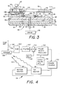
- Fig. 4 is a block diagram of a heater control system for energizing top and bottom heaters of the chamber.
- In Fig. 1, there is shown an
analytical instrument 20 which provides automatically a sequence of process steps to accomplish an assay of a test sample. A plurality ofcartridges 22 are employed within theinstrument 20 to increase the throughput rate, one process step being carried out with one cartridge concurrently with the performance of other process steps with other cartridges. Thecartridges 22 are illustrated with respect to a preferred embodiment thereof which includes one or more chambers in the housing. Such chambers may be configured as wells, or reservoirs, for the storage and/or mixing of fluids which are used in the assay procedure or the chambers may culminate in an opening to permit fluids to be provided to a reaction zone within the cartridge. The chambers are formed integrally within the housing of the cartridge. Theanalytical instrument 20 includes a conveyor, or carousel, 24, which is rotated about anaxle 26 by amotor 28. By way of example, themotor 28 may be mechanically coupled to thecarousel 24 by agear 30 or by a belt drive (not shown). Thecarousel 24 carries thecartridges 22 from one work station to another work station, twosuch work stations carousel 24 rotates within a temperature controlledchamber 36 having a heater 38 for maintaining a desired temperature at the various work stations so as to allow for a process step of incubation. -
Work station 32 is a pipetting station whereat sample fluid and any other required fluid test reagent(s) are delivered to theassay cartridges 22. By way of example, there are shown twopipettes pipette mechanism 44 mechanically connected to thepipettes - During the assay procedure, as a result of the reaction(s) and interaction(s) between the sample fluid and the test reagent(s) which take place, a detectable change is effected corresponding to the presence of an analyte or component of interest in the sample fluid. The detectable change may be a color change which may be read spectrophotometrically such as with a densitometer or, in an assay method based on fluorescent-labeled biologically active species or one which involves the generation of a fluorescent species as a result of a reaction between test reagents, a fluorescent output signal can be generated and read spectrofluorometrically. Such detectable changes may be read from above or below the assay cartridge. At
work station 34 there is shown by way of example afluorometer 46 for irradiating the reaction zone within the assay cartridge and for measuring the fluorescence emitted from the fluorescent species present therein. - The
carousel 24 may be arranged so as to accommodate varying numbers ofassay cartridges 22. Each position, orberth 54 for holding an assay cartridge is provided in this embodiment with asmall aperture 56 to allow the irradiating illumination to reach the reaction zone in the assay cartridge and to permit the reflected fluorescent emissions to be collected and measured. Also shown in aninjector 58 for inserting acartridge 22 in anempty berth 54, theinjector 58 having anarm 60 for gripping acartridge 22 during the insertion operation. Theinjector 58 also serves to extract a cartridge from aberth 54 by use of thearm 60 upon completion of a test procedure. Operation of themotor 28, thepipette mechanism 44, thefluorometer 46 and theinjector 58 are synchronized by means of amicroprocessor unit 62. - Referring now to Fig. 2 and 3 there is shown a preferred embodiment of a temperature controlled chamber according to the invention and its operation within the
analytical instrument 20. This preferred embodiment is operative with only a single pipette, for example, thepipette 40. Thepipette mechanism 44 comprises atransport 64 for moving thepipette 40 in a radial direction (X) of thechamber 36 between thechamber 36 and aselectable reservoir 66 of a plurality ofreservoirs 66. Thereservoirs 66 are carried upon a table 68 which may be translated in a direction (Y) perpendicular to the pipette movement, X, of thetransport 64 so as to enable two axes (X and Y) selection of areservoir 66 containing a desired fluid. Motorized drives for thetransport 64 and the table 68 are available commercially and, accordingly, need not be described in detail herein. In these types of analytical instruments disposable pipette tips are typically used for the delivery of one fluid only and then discarded so as to avoid contamination which could lead to errors in the assay result. Accordingly, the table 68 carries a supply oftips 70 to be inserted upon astem 72 of thepipette 40. Atip 70 is attached to thestem 72 with frictional force by pushing thestem 72 down into atip 70 on the table 68. Thetip 70 is extracted from thestem 72 by anextractor 74 located alongside the table 68, theextractor 74 having a hookedflange 76 which envelops thetip 70 to pull off thetip 70 during an upward motion of thetip 70. - In accordance with the invention, the temperature controlled
chamber 36 comprises atop wall 78, located above thecarousel 24, abottom wall 80 located below thecarousel 24, and two sidewalls wherein one of the sidewalls is anouter wall 82 which extends from thetop wall 78 to thebottom wall 80 and the second of the sidewalls is aninner wall 84 which extends from thetop wall 78 toward a central portion of thecarousel 24. Thetop wall 82 has an annular shape. Anupper region 86 of thechamber 36 is bounded by thetop wall 78, thetop surface 88 of thecarousel 24, the outer sidewlll 82 and theinner sidewall 84. - In this preferred embodiment the sample fluid and any other required fluid reagents are dispensed to the
assay cartridges 22 while the latter are in the temperature controlled chamber. Accordingly, in order to provide access to theassay cartridges 22 by thepipette 40, aslot 90 is provided in thetop wall 78 of thechamber 36. Theslot 90 extends in a radial direction of thechamber 36, parallel to the X direction. Theslot 90 is located relative to thetransport 64 to permit thestem 72 of thepipette 40 to be lowered through theslot 90 selectively above a desired compartment of a plurality ofcompartments 92 of theassay cartridge 22. The length of theslot 90 is commensurate with the length of thecartridge 22 to permit displacement of thestem 72 in the X direction for alignment with a selected one of thecompartments 92. Theslot 90 is relatively narrow, and is surrounded by agrommet 94. Theslot 90 has a width large enough to clear thestem 72 and thetip 70 mounted on the distal end of thestem 72. With respect to the overall dimension of thechamber 36, the area occupied by theslot 90 is sufficiently small to preclude any significant amount of air flow between the interior and the exterior of thechamber 36. Thereby, theslot 90 has no more than a negligible effect in the control of the temperature of the chamber. - The
chamber 36 further comprises two heaters, namely, atop heater 96 supported by thetop wall 78, and abottom heater 98 supported by thebottom wall 80 for controlling the chamber temperature. Thebottom heater 98 is located in alower region 100 of thechamber 36, between thecarousel 24 and thebottom wall 80. Aninjection port 102 is provided in theouter sidewall 82 facing theinjector 58 to provide access to thearm 60 for inserting acartridge 22 in aberth 54 of thecarousel 24, and for extracting thecartridge 22 from theberth 54. Aframe 104 is located within theupper region 86 for supporting sensors useful in the operation of the temperature control system, onesuch sensor 106 being provided for sensing the chamber temperature. Theframe 104 is secured by abracket 108 to theouter wall 82. By way of example in the construction of theframe 104, theframe 104 may be constructed as a circuit board for supporting electronic circuitry (not shown in Fig. 3) such as a preamplifier for amplifying electrical signals provided by thesensor 106.Electrical cables top heater 96, thebottom heater 98, and thesensors - To facilitate maintaining a substantially constant temperature within the
chamber 36, it is advisable to minimize any flow of air between the interior of thechamber 36 and the external environment. Accordingly, theinner sidewall 84 meets thetop surface 88 of thecarousel 24 at anairlock 118 which provides sufficient clearance of space between theinner sidewall 84 and thecarousel 24 to allow for relative motion between thecarousel 24 and theinner sidewall 84, the clearance space being sufficiently narrow to inhibit flow of air between the interior of thechamber 36 and the external environment. Theairlock 118 comprises an innercircular rib 120 and an outercircular rib 122 which are spaced apart radially from each other to form a channel for receiving alip 124 of theinner sidewall 84. Theshaft 26 which supports thecarousel 24 passes through anaperture 126 in thebottom wall 80. Theaperture 126 provides a clearance space which permits rotation of theshaft 26, the rotation being provided by adrive unit 128. The clearance space of theaperture 126 inhibits the flow of air between the interior of thechamber 36 and the external environment. Thus, thebottom wall 80, in combination with the clearance space of theaperture 126 may be regarded as anairlock 130. - The remaining openings in which air may be exchanged between the interior and exterior of the
chamber 36 are theinjection port 102 and thepipette slot 90. Theport 102 is essentially closed off by the structure of theinjector 58 except during passage of acartridge 22 through theport 102. Theslot 90 has dimensions such that no more than a negligible amount of air is interchanged between the interior of the chamber and the external environment. For example, for acarousel 24 having a diameter of about 33 cm (13 inches), theslot 90 can have a width less than about 0.64 cm (one-quarter inch) and a length less than about 3.3 cm (1.3 inches). Also, it is noted that the volume of thelower region 100 is sufficiently small, and agap 132 between thecarousel 24 and theouter wall 82 is sufficiently small as to minimize airflow between theupper region 86 and thelower region 100 of thechamber 36. Also, the volume of theupper region 86 is no larger than necessary to accommodate the physical sizes of thecartridges 22 and the sensor assembly 134 comprising theframe 104 and thesensor 106. Minimizing the interior volume of theupper region 86 increases the dynamic response of atemperature control system 136 and reduces transients in the reponse of thetemperature control system 136 to be described below with reference to Fig. 4. The toroidal shape of theupper region 86 aids in reducing the volume of theupper region 86. - Additionally, to maintain circulation of air from the
upper region 86 to thelower region 100 there are provided a plurality of apertures, or vents, in thecarousel 24 together with a fin to direct the air through the aperture as the carousel is rotated. Onesuch aperture 110 is shown with thefin 111 for purposes of illustration. In a preferred embodiment eight such apertures, each about 1.3 cm x 0.64 cm (1/2˝ x 1/4˝), are provided in the carousel. Further, since the carousel may be rotated in either direction it is preferred to arrange half of the fins in each direction to facilitate circulation of air irrespective of the direction of rotation. - In Fig. 4, the
temperature control system 136 comprises thetemperature sensor 106 and theheaters temperature control system 136 comprises atemperature setting potentiometer 138, asubtracter 140, afilter 142, asummer 144, asource 146 of a reference voltage, apulse width modulator 148, aclock pulse generator 150, and apower source 152. - In operation, the
potentiometer 138 is connected between a voltage, V, and ground to provide a manually adjustable output voltage atterminal 154 which is applied to a first terminal of thesubtracter 140. An output voltage of thesensor 106 is connected to a second input terminal of thesubtracter 140. Thesubtracter 140 comprises well-known circuitry, such as that of an operational amplifier (not shown), for forming the difference between the voltages of thepotentiometer 138 and thesensor 106, and applies the difference to thefilter 142. Theheaters power source 152, thesource 152 applying electric current to theheaters waves 156 propagating from theheaters temperature sensor 106. - The
power source 152 is gated on and off by pulses provided by thegenerator 150 via themodulator 148. The voltage reference of thesource 146 is applied via thesummer 144 to themodulator 148 to establish a basic width to pulses outputted by themodulator 148 to thepower source 152. The repetition frequency of the pulses is established by thegenerator 150. The basic pulse width, in combination with the repetition frequency, establishes a duty cycle for the administration of energizing current to theheaters carousel 24. An output voltage of thefilter 142 is applied to thesummer 144 to be added algebraically with the reference voltage of thesource 146 to adjust the pulse width as needed to increase or decrease the amount of heat produced by theheaters sensor 106, in response to the chamber temperature provided by theheaters potentiometer 138, then the error signal outputted by thesubtracter 140 is zero, and themodulator 148 outputs pulses at the basic pulse width. - The circuitry of Fig. 4 may be viewed as a feedback loop in which the
waves 156 of heat complete the loop by connecting theheaters temperature sensor 106. If thesensor 106 outputs a voltage different from that of thepotentiometer 138, a loop error signal outputted by thesubtracter 140 has the proper sense, positive or negative, and proper amplitude to adjust the width of the pulses outputted by themodulator 148 for maintaining the desired chamber temperature. For example, if the sensed temperature is too low, the pulse width is increased, and if the sensed temperature is too high, the pulse width is decreased. Thefilter 142 may be a low-pass filter as is customarily employed in feedback circuitry for precise control of the dynamic response of a feedback loop. - It should be noted here that the system may be controlled entirely by appropriately programming the microprocessor software. In this preferred embodiment the
subtracter 140,filter 142,summer 144,source 146,pulse width modulator 148 andclock pulse generator 150 are not necessary. - The main source of interruption of the temperature of the chamber is the insertion of the
assay cartridges 22 via theport 102 since the assay cartridges are typically at room temperature which typically is from fifteen to twenty degrees less than that of the chamber. In typical automated analytical instruments the introduction of assay cartridges to the carousel within the chamber can occur at a rate of one every ten seconds, the duration of such rate being dependent, of course, upon the number ofopen berths 54 on the carousel. Even though acartridge 22 may be retained within thechamber 36 for a minute or longer prior to beginning the assay procedure in order to stabilize the cartridge temperature, attainment of a desired temperature of the cartridge and of the test material and any reagents contained within the cartridge can only be accomplished adequately by maintaining the chamber temperature in the vicinity of the carousel and the cartridge within the desired range, e.g., 37° ± 0.5°C. Thus, the perturbations in temperature resulting from the frequent introduction of assay cartridges and removal of the cartrdiges after the assay procedure has been completed can result in rapid undulations in the chamber temperature which can cause the temperature in the vicinity of the carousel and the assay cartridges to be outside the desired range. - In order to maintain this desired temperature, and to prevent excessive undulations due to the injection of assay cartridges, the pulse repetition frequency provided by the
generator 150 is preferably at least double the rate of introduction of assay cartridges, the Nyquist criteria. For example, the current pulses provided by thepower source 152 may occur at a repetition frequency of one pulse every three seconds. The average duration of a pulse may be two seconds. This provides a dynamic response to thetemperature control system 136 which is adequately fast to deal with the rate of cartridge introduction. Thetemperature sensor 106 is placed immediately above a plane containing the top surfaces of thecartridges 22 so as to sense the temperature accurately at the openings of the cartridge compartments 92. Also, as has been noted hereinabove, the volume of theupper region 86 is minimized to reduce the amount of air which must be heated, and to reduce the amount of air currents which might otherwise flow about within thechamber 36. - The use of a metallic, thermally conductive,
inner sidewall 84 in conjunction with the use of the metallic, thermally-conductivetop wall 78 extends a region of heating to a major portion of theupper region 86 for improved thermal response. It is noted that while thebottom wall 80 and thecarousel 24 are formed of polymeric material having a relatively low conductivity, there are no openings, such as theinjection port 102, in thelower region 100 of thechamber 36 so that the temperature of the lower region can remain stable by the inclusion of thebottom heater 98 in thelower region 100. Therefore, it is possible to construct thebottom wall 80 and theouter sidewall 82 of polymeric material which facilitates and lessens the cost of manufacture, and that only the annulartop wall 78 and the cylindricalinner sidewlall 84 need be formed of metal. Any suitable polymeric material may be used for the bottom wall and the outer sidewall such as polyurethane, polycarbonate or the like. - It is understood that the above described embodiment of the invention is illustrative only, and that modifications thereof may occur to those skilled in the art. Accordingly, this invention is not to be regarded as limited to the embodiment disclosed herein, but is to be limited only as defined by the appended claims.
Claims (14)
- A temperature controlled chamber (36) for use in an analytical instrument (20) in which a fluid is dispensed to an assay element (22) carried by a circular conveyor (24) and the assay element (22) is analyzed after a period of incubation, said chamber (36) comprising means defining a temperature controlled chamber (36) extending circumferentially around the outer periphery of a circular conveyor (24), heating means (38) and means (58) for introducing said assay element (22) onto said conveyor (24), characterized in that said means defining a temperature controlled chamber (36) extends radially inward partway to the center of said conveyor (24) for enclosing the peripheral region of said conveyor (24) carrying said assay element (22) while exposing a central region of said conveyor (24), said chamber (36) including an outer sidewall (82) and an inner sidewall (84) arranged radially inward of said outer sidewall (82), a top wall (78) spaced above said conveyor (24) and joining said inner and outer sidewalls (84, 82), first airlock means (118) joining said inner sidewall (84) to said conveyor (24) and second airlock means (130) joining said outer sidewall (82) to said conveyor (24), said outer sidewall (84) comprising a polymeric material and said top wall (78) and said inner sidewall (82) comprising a metallic material, that said heating means (38) comprises a first heating element (96) located above said conveyor (24), a second heating element (98) located below said conveyor (24) and means (136) for pulsing an electric current to said heating elements (96, 98) at a rate sufficient to maintain the temperature of said assay element (22) within a predeterment range, and that said assay element (22) is introduced onto said conveyor (24) through an opening (102) in said chamber (36).
- The temperature controlled chamber (36) as defined in claim 1 wherein said outer sidewall (82) extends from a region above said conveyor (24) past an outer edge of said conveyor (24) to a region below said conveyor (24), and said second airlock means (130) comprises a bottom wall (80) extending beneath said conveyor (24) and connecting with said outer sidewall (82).
- The temperature controlled chamber (36) as defined in claim 1 wherein said first air lock means (118) comprises a lip (124) formed on a bottom edge of said inner sidewall (84) and channel means located on a top surface of said conveyor (24), said channel means enveloping said lip (124).
- The temperature controlled chamber (36) as defined in claim 3 wherein said outer wall (82) extends from a region above said conveyor (24) past an outer edge of said conveyor (24) to a region below said conveyor (24), and said second airlock means (130) comprises a bottom wall (80) extending beneath said conveyor (24) and connecting with said outer wall (82).
- The temperature controlled chamber (36) as defined in claim 1 wherein the peripheral region of said conveyor (24) which is enclosed by said chamber (36) includes at least one aperture (110), each said aperture (110) having in association therewith means (111) for directing a flow of air through said aperture (110).
- The temperature controlled chamber (36) as defined in claim 5 wherein said bottom wall (80) is provided with an aperture (126) for allowing passage of a mounting shaft (26) through said bottom wall (80) to said conveyor (24) for imparting relative motion between said conveyor (24) and said chamber (36).
- The temperature controlled chamber (36) as defined in claim 6 wherein said chamber (36) is operative with a pipette (40) for dispensing fluid to said assay element (22), and said chamber (36) comprises:
a radially extending slot (90) disposed in said top wall (78) for allowing entry of the pipette (40) into an interior region of said chamber (36) for dispensing fluid to said assay element (22); and
wherein said temperature-maintaining means (38) includes means (106) located within said enclosure for sensing temperature within said chamber (36). - The temperature controlled chamber (36) as defined in claim 7 wherein said temperature-maintaining means (38) includes a top heater (96) disposed on said top wall (78) and a bottom heater (98) disposed on said bottom wall (80), and means for activating said top heater (96) and said bottom heater (98) concurrently in response to said sensing means (106).
- The temperature controlled chamber (36) as defined in claim 8 wherein said top heater (96) is coextensive with said top wall (78) and bottom heater (98) is coextensive with bottom wall (80).
- The temperature controlled chamber (36) as defined in claim 9 wherein said top wall (78) and said inner wall (84) are constructed each of thermally conductive material.
- The temperature controlled chamber (36) as defined in claim 10 wherein said thermally conductive material is a metal, said outer wall (82) and said bottom wall (80) are constructed each of a polymeric material, and said sample port (102) is located in said outer wall (82).
- The temperature controlled chamber (36) as defined in claim 11 wherein said conveyor (24) is configured for holding a plurality of assay elements (22) disposed side-by-side along a peripheral region of said conveyor (24) and within said enclosure, said outer sidewall (82) being spaced apart from an outer periphery of said conveyor (24) by a clearance spacing (132), said sensing means (106) being located above said assay elements (22); and
a radial distance between said inner and said outer sidewalls (84, 82) is commensurate with a radial extent of said assay elements (22), and a vertical distance between said top wall (78) and said conveyor (24) is commensurate with a height of said assay elements (22) plus a height of said sensing means (106, 110) to minimize an enclosed volume of said enclosure for improved speed of thermal response of said chamber (36). - The temperature controlled chamber (36) as defined in claim 12 wherein assay elements (22) are passed through said opening (102) sequentially at a predetermined rate, and said heater activating means (136) energizes said heaters (96, 98) with pulses of electric current at a repetition frequency at least double said assay element (22) passing rate for improved speed of thermal response of said chamber (36), a duration of said current pulses being modulated by said heater activating means (136) to provide for increased pulse duration for raising the temperature and reduced pulse duration for reducing the temperature.
- The temperature controlled chamber (36) as defined in claim 8 wherein assay elements (22) are passed through said opening (102) sequentially at a predetermined rate, and said heater activating means (136) energizes said heaters (96, 98) with pulses of electric current at a repetition frequency at least double said assay element (22) passing rate for improved speed of thermal response of said chamber (36), a duration of said current pulses being modulated by said heater activating means (136) to provide for increased pulse duration for raising the temperature and reduced pulse duration for reducing the temperature.
Applications Claiming Priority (3)
| Application Number | Priority Date | Filing Date | Title |
|---|---|---|---|
| US526048 | 1983-08-24 | ||
| US07/526,048 US5207987A (en) | 1990-05-21 | 1990-05-21 | Temperature controlled chamber for diagnostic analyzer |
| PCT/US1991/001839 WO1991018295A1 (en) | 1990-05-21 | 1991-03-20 | Temperature controlled chamber for diagnostic analyzer |
Publications (2)
| Publication Number | Publication Date |
|---|---|
| EP0483300A1 EP0483300A1 (en) | 1992-05-06 |
| EP0483300B1 true EP0483300B1 (en) | 1995-08-30 |
Family
ID=24095714
Family Applications (1)
| Application Number | Title | Priority Date | Filing Date |
|---|---|---|---|
| EP91906830A Expired - Lifetime EP0483300B1 (en) | 1990-05-21 | 1991-03-20 | Temperature controlled chamber for diagnostic analyzer |
Country Status (9)
| Country | Link |
|---|---|
| US (1) | US5207987A (en) |
| EP (1) | EP0483300B1 (en) |
| JP (1) | JP2825651B2 (en) |
| AT (1) | ATE127233T1 (en) |
| CA (1) | CA2039601A1 (en) |
| DE (1) | DE69112565T2 (en) |
| DK (1) | DK0483300T3 (en) |
| ES (1) | ES2080306T3 (en) |
| WO (1) | WO1991018295A1 (en) |
Families Citing this family (63)
| Publication number | Priority date | Publication date | Assignee | Title |
|---|---|---|---|---|
| US5192506A (en) * | 1991-02-14 | 1993-03-09 | P B Diagnostic Systems, Inc. | Incubator port closure for automated assay system |
| KR940011743B1 (en) * | 1991-05-13 | 1994-12-23 | 금성일렉트론주식회사 | Prewarming apparatus for semiconductor device |
| US6180061B1 (en) | 1992-05-11 | 2001-01-30 | Cytologix Corporation | Moving platform slide stainer with heating elements |
| US20040191128A1 (en) * | 1992-05-11 | 2004-09-30 | Cytologix Corporation | Slide stainer with heating |
| CA2096198A1 (en) * | 1992-06-26 | 1993-12-27 | Christopher J. Macko | Automated clinical analyzer with temperature control |
| CA2130013C (en) * | 1993-09-10 | 1999-03-30 | Rolf Moser | Apparatus for automatic performance of temperature cycles |
| CA2130517C (en) * | 1993-09-10 | 1999-10-05 | Walter Fassbind | Array of reaction containers for an apparatus for automatic performance of temperature cycles |
| US5374395A (en) * | 1993-10-14 | 1994-12-20 | Amoco Corporation | Diagnostics instrument |
| US5525300A (en) * | 1993-10-20 | 1996-06-11 | Stratagene | Thermal cycler including a temperature gradient block |
| JP3051626B2 (en) * | 1993-12-09 | 2000-06-12 | 富士写真フイルム株式会社 | incubator |
| DE4428228C2 (en) * | 1994-08-10 | 1996-07-25 | Eppendorf Geraetebau Netheler | Handling system for reaction vessels |
| US6156565A (en) * | 1996-02-21 | 2000-12-05 | Biomerieux, Inc. | Incubation station for test sample cards |
| ATE318327T1 (en) * | 1996-06-04 | 2006-03-15 | Univ Utah Res Found | FLUORESCENCE-DONOR-ACCEPTOR PAIR |
| US5908599A (en) * | 1996-07-30 | 1999-06-01 | Bayer Corporation | Heated reaction chamber in a unified fluid circuit of a hematology diagnostic instrument |
| ES2133129B1 (en) * | 1997-11-19 | 2000-05-01 | Grifols Grupo Sa | APPARATUS FOR THE AUTOMATIC PERFORMANCE OF LABORATORY TESTS. |
| CZ9803755A3 (en) * | 1997-11-19 | 2001-08-15 | Grupo Grifols, S. A. | Apparatus for automatic execution of laboratory tests |
| US6183693B1 (en) * | 1998-02-27 | 2001-02-06 | Cytologix Corporation | Random access slide stainer with independent slide heating regulation |
| DE69942975D1 (en) | 1998-02-27 | 2011-01-05 | Ventana Med Syst Inc | AUTOMATED MOLECULAR PATHOLOGY APPARENT WITH INDEPENDENT OBJECT CARRIER WARMERS |
| US6582962B1 (en) * | 1998-02-27 | 2003-06-24 | Ventana Medical Systems, Inc. | Automated molecular pathology apparatus having independent slide heaters |
| CA2324281A1 (en) * | 1998-03-23 | 1999-09-30 | Cepheid | Multi-site reactor system with dynamic, independent control of individual reaction sites |
| DE69936897T2 (en) | 1998-05-01 | 2008-05-15 | Gen-Probe Inc., San Diego | Incubator for automatic analyzer |
| US8337753B2 (en) | 1998-05-01 | 2012-12-25 | Gen-Probe Incorporated | Temperature-controlled incubator having a receptacle mixing mechanism |
| US6780606B1 (en) | 1999-02-26 | 2004-08-24 | Synx Pharma, Inc. | Method for diagnosing and distinguishing stroke and diagnostic devices for use therein |
| DE19916748A1 (en) * | 1999-04-14 | 2000-10-19 | Zeiss Carl Jena Gmbh | Fluorescence reaction analysis unit, comprises a transparent container with an adjustable cover that has at least one opening. |
| WO2002061858A2 (en) * | 2000-11-17 | 2002-08-08 | Thermogenic Imaging, Inc. | Apparatus and methods for infrared calorimetric measurements |
| US20040110301A1 (en) * | 2000-11-17 | 2004-06-10 | Neilson Andy C | Apparatus and methods for measuring reaction byproducts |
| US20020132360A1 (en) * | 2000-11-17 | 2002-09-19 | Flir Systems Boston, Inc. | Apparatus and methods for infrared calorimetric measurements |
| US7217391B2 (en) * | 2001-03-16 | 2007-05-15 | Beckman Coulter, Inc. | Rotary incubation station for immunoassay systems |
| US7425306B1 (en) | 2001-09-11 | 2008-09-16 | Ventana Medical Systems, Inc. | Slide heater |
| US7270785B1 (en) * | 2001-11-02 | 2007-09-18 | Ventana Medical Systems, Inc. | Automated molecular pathology apparatus having fixed slide platforms |
| US6889468B2 (en) * | 2001-12-28 | 2005-05-10 | 3M Innovative Properties Company | Modular systems and methods for using sample processing devices |
| US11249095B2 (en) | 2002-04-15 | 2022-02-15 | Ventana Medical Systems, Inc. | Automated high volume slide processing system |
| US7468161B2 (en) | 2002-04-15 | 2008-12-23 | Ventana Medical Systems, Inc. | Automated high volume slide processing system |
| EP1494808B1 (en) * | 2002-04-15 | 2013-07-03 | Ventana Medical Systems, Inc. | Automated high volume slide staining system |
| EP2420814B1 (en) * | 2002-04-26 | 2015-08-26 | Ventana Medical Systems, Inc. | Automatic slide processing apparatus |
| CN100373820C (en) * | 2003-10-08 | 2008-03-05 | 松下电器产业株式会社 | Road-vehicle communication system, and roadside apparatus, mobile apparatus which are used for the same |
| EP1697719B1 (en) | 2003-12-23 | 2018-09-19 | Ventana Medical Systems, Inc. | Method and apparatus for efficient thin film fluid processing of flat surfaces |
| US7964413B2 (en) | 2005-03-10 | 2011-06-21 | Gen-Probe Incorporated | Method for continuous mode processing of multiple reaction receptacles in a real-time amplification assay |
| US7670553B2 (en) * | 2005-03-24 | 2010-03-02 | Siemens Healthcare Diagnostics Inc. | Carousel system for automated chemical or biological analyzers employing linear racks |
| US7763210B2 (en) * | 2005-07-05 | 2010-07-27 | 3M Innovative Properties Company | Compliant microfluidic sample processing disks |
| US7754474B2 (en) * | 2005-07-05 | 2010-07-13 | 3M Innovative Properties Company | Sample processing device compression systems and methods |
| US7323660B2 (en) * | 2005-07-05 | 2008-01-29 | 3M Innovative Properties Company | Modular sample processing apparatus kits and modules |
| EP2069800B1 (en) * | 2006-09-22 | 2012-03-28 | Fujifilm Corporation | Clinical analysis apparatus |
| US20100108514A1 (en) * | 2007-03-30 | 2010-05-06 | Fujifilm Coporation | Method of controlling temperature |
| AU2009313985B2 (en) | 2008-11-12 | 2014-07-31 | Ventana Medical Systems, Inc. | Methods and apparatuses for heating slides carrying specimens |
| WO2011042426A1 (en) * | 2009-10-05 | 2011-04-14 | Alphahelix Molecular Diagnostics Ab (Publ) | Multifunctional rotor |
| FI20096021A0 (en) | 2009-10-06 | 2009-10-06 | Wallac Oy | Optical measuring instrument |
| USD638951S1 (en) | 2009-11-13 | 2011-05-31 | 3M Innovative Properties Company | Sample processing disk cover |
| US20110117607A1 (en) * | 2009-11-13 | 2011-05-19 | 3M Innovative Properties Company | Annular compression systems and methods for sample processing devices |
| US8834792B2 (en) | 2009-11-13 | 2014-09-16 | 3M Innovative Properties Company | Systems for processing sample processing devices |
| USD638550S1 (en) | 2009-11-13 | 2011-05-24 | 3M Innovative Properties Company | Sample processing disk cover |
| USD667561S1 (en) | 2009-11-13 | 2012-09-18 | 3M Innovative Properties Company | Sample processing disk cover |
| US9289768B2 (en) * | 2010-01-11 | 2016-03-22 | Waters Technologies Corporation | Apparatus for reducing variation in sample temperatures in a liquid chromatography system |
| US9046507B2 (en) | 2010-07-29 | 2015-06-02 | Gen-Probe Incorporated | Method, system and apparatus for incorporating capacitive proximity sensing in an automated fluid transfer procedure |
| CN103403533B (en) | 2011-02-24 | 2017-02-15 | 简.探针公司 | Systems and methods for distinguishing optical signals of different modulation frequencies in an optical signal detector |
| WO2012158990A1 (en) | 2011-05-18 | 2012-11-22 | 3M Innovative Properties Company | Systems and methods for volumetric metering on a sample processing device |
| USD672467S1 (en) | 2011-05-18 | 2012-12-11 | 3M Innovative Properties Company | Rotatable sample processing disk |
| JP2014517291A (en) | 2011-05-18 | 2014-07-17 | スリーエム イノベイティブ プロパティズ カンパニー | System and method for valve operation of a sample processing apparatus |
| JP6235462B2 (en) | 2011-05-18 | 2017-11-22 | スリーエム イノベイティブ プロパティズ カンパニー | System and method for detecting the presence of a selected volume of material in a sample processing apparatus |
| EP4095509A1 (en) | 2013-12-13 | 2022-11-30 | Ventana Medical Systems, Inc. | Automated histological processing of biological specimens and associated technology |
| JP7100985B2 (en) * | 2018-01-25 | 2022-07-14 | シスメックス株式会社 | Method of circulating air in the sample measuring device and reagent storage |
| BR112022015994A2 (en) | 2020-02-13 | 2022-10-11 | Univ Illinois | MULTIVALENT IMMUNOGENIC COMPOSITION, RECOMBINANT VECTOR, RECOMBINANT HOST CELL, AND, METHODS FOR INDUCING A PROTECTIVE IMMUNE RESPONSE AND FOR IMMUNIZING AN ANIMAL AGAINST DIROPHILARIOSIS |
| WO2022169835A1 (en) | 2021-02-03 | 2022-08-11 | The Board Of Trustees Of The University Of Illinois | Vaccine and methods for preventing filariasis and dirofilariasis |
Family Cites Families (23)
| Publication number | Priority date | Publication date | Assignee | Title |
|---|---|---|---|---|
| SE327841B (en) * | 1968-02-16 | 1970-08-31 | Autokemi Ab | |
| US3574064A (en) * | 1968-05-09 | 1971-04-06 | Aerojet General Co | Automated biological reaction instrument |
| US3863049A (en) * | 1972-05-31 | 1975-01-28 | Union Carbide Corp | Temperature control apparatus for a centrifugal-type chemistry analyzer |
| US3916152A (en) * | 1972-05-31 | 1975-10-28 | Union Carbide Corp | Temperature control system for a centrifugal-type chemistry analyzer |
| US3969079A (en) * | 1975-01-08 | 1976-07-13 | Alphamedics Mfg. Corporation | Dual channel photo-optical clot detection apparatus |
| US4298571A (en) * | 1976-12-17 | 1981-11-03 | Eastman Kodak Company | Incubator including cover means for an analysis slide |
| US4224032A (en) * | 1976-12-17 | 1980-09-23 | Eastman Kodak Company | Method and apparatus for chemical analysis |
| US4219529A (en) * | 1977-11-28 | 1980-08-26 | Eastman Kodak Company | Incubator for chemical analyzer |
| US4406547A (en) * | 1979-08-07 | 1983-09-27 | Olympus Optical Company Limited | Apparatus for effecting automatic analysis |
| US4276258A (en) * | 1980-01-28 | 1981-06-30 | Coulter Electronics, Inc. | Sample and stat feeding system and sample tray |
| US4296069A (en) * | 1980-06-16 | 1981-10-20 | Eastman Kodak Company | Apparatus for processing an analysis slide |
| US4303611A (en) * | 1980-08-11 | 1981-12-01 | Eastman Kodak Company | Analyzer apparatus featuring a simplified incubator |
| JPS5772047A (en) * | 1980-10-24 | 1982-05-06 | Olympus Optical Co Ltd | Component analyzing method |
| US4497774A (en) * | 1981-06-19 | 1985-02-05 | Medical Laboratory Automation, Inc. | Coagulation instrument for performing clotting tests |
| JPS5821566A (en) * | 1981-07-31 | 1983-02-08 | Fuji Photo Film Co Ltd | Incubator |
| US4568519A (en) * | 1983-06-29 | 1986-02-04 | Eastman Kodak Company | Apparatus for processing analysis slides |
| FI833076A0 (en) * | 1983-08-30 | 1983-08-30 | Labsystems Oy | ANORDNING FOER MAETNING AV UPPVAERMBARA VAETSKEPROV |
| DE3405293A1 (en) * | 1984-02-15 | 1985-09-05 | Eppendorf Gerätebau Netheler + Hinz GmbH, 2000 Hamburg | METHOD FOR TEMPERING A SAMPLE LIQUID TO BE ANALYZED, REAGENTS FOR CARRYING OUT ANALYZES AND DEVICE FOR CARRYING OUT THE METHOD |
| JPS6113162A (en) * | 1984-06-28 | 1986-01-21 | Konishiroku Photo Ind Co Ltd | Biochemical analyser |
| JPS61194336A (en) * | 1985-02-25 | 1986-08-28 | Toshiba Corp | Automatic chemical analyser |
| US4670219A (en) * | 1985-02-27 | 1987-06-02 | Fisher Scientific Company | Liquid handling |
| JPS61274268A (en) * | 1985-05-30 | 1986-12-04 | Toshiba Corp | Automatic chemical analyzer |
| US5051238A (en) * | 1987-11-20 | 1991-09-24 | Hitachi, Ltd. | Automatic analyzing system |
-
1990
- 1990-05-21 US US07/526,048 patent/US5207987A/en not_active Expired - Fee Related
-
1991
- 1991-03-20 WO PCT/US1991/001839 patent/WO1991018295A1/en active IP Right Grant
- 1991-03-20 DK DK91906830.4T patent/DK0483300T3/en active
- 1991-03-20 AT AT91906830T patent/ATE127233T1/en not_active IP Right Cessation
- 1991-03-20 ES ES91906830T patent/ES2080306T3/en not_active Expired - Lifetime
- 1991-03-20 JP JP3507275A patent/JP2825651B2/en not_active Expired - Lifetime
- 1991-03-20 EP EP91906830A patent/EP0483300B1/en not_active Expired - Lifetime
- 1991-03-20 DE DE69112565T patent/DE69112565T2/en not_active Expired - Fee Related
- 1991-04-02 CA CA002039601A patent/CA2039601A1/en not_active Abandoned
Also Published As
| Publication number | Publication date |
|---|---|
| ATE127233T1 (en) | 1995-09-15 |
| US5207987A (en) | 1993-05-04 |
| EP0483300A1 (en) | 1992-05-06 |
| DE69112565D1 (en) | 1995-10-05 |
| WO1991018295A1 (en) | 1991-11-28 |
| JPH05500115A (en) | 1993-01-14 |
| JP2825651B2 (en) | 1998-11-18 |
| DK0483300T3 (en) | 1996-01-02 |
| ES2080306T3 (en) | 1996-02-01 |
| DE69112565T2 (en) | 1996-02-01 |
| CA2039601A1 (en) | 1991-11-22 |
Similar Documents
| Publication | Publication Date | Title |
|---|---|---|
| EP0483300B1 (en) | Temperature controlled chamber for diagnostic analyzer | |
| JP2731626B2 (en) | How to calibrate an automated analyzer | |
| KR100291650B1 (en) | Incubation station for test sample cards | |
| US7666355B2 (en) | Automated analyzer | |
| US5192506A (en) | Incubator port closure for automated assay system | |
| US5051238A (en) | Automatic analyzing system | |
| US4366118A (en) | Apparatus and method for luminescent determination of concentration of an analyte in a sample | |
| JP3088542B2 (en) | Electrophoresis device | |
| US3971630A (en) | Apparatus and method for batch-type analysis of liquid samples | |
| EP0238582B1 (en) | Method for immunological determinations | |
| JP2005500545A (en) | Reagent containers and canisters for use in automated microbial analyzers | |
| JP2005500544A (en) | Canister for inventory susceptibility testing equipment in automated microbial analyzers | |
| JP2004520594A (en) | A method to minimize optical interference during antibiotic susceptibility readings in microbial analyzers | |
| EP0504313A4 (en) | ||
| WO1991019199A1 (en) | Automated analytical instrument | |
| GB2025609A (en) | Determination of concentration of an analyte in a sample | |
| JPH0672846B2 (en) | Chemical analyzer | |
| CA1070137A (en) | Analyzer for liquid samples | |
| JPH0672847B2 (en) | Chemical analyzer |
Legal Events
| Date | Code | Title | Description |
|---|---|---|---|
| PUAI | Public reference made under article 153(3) epc to a published international application that has entered the european phase |
Free format text: ORIGINAL CODE: 0009012 |
|
| AK | Designated contracting states |
Kind code of ref document: A1 Designated state(s): AT BE CH DE DK ES FR GB IT LI LU NL SE |
|
| 17P | Request for examination filed |
Effective date: 19920514 |
|
| 17Q | First examination report despatched |
Effective date: 19940214 |
|
| RAP1 | Party data changed (applicant data changed or rights of an application transferred) |
Owner name: BEHRING DIAGNOSTICS INC. |
|
| GRAA | (expected) grant |
Free format text: ORIGINAL CODE: 0009210 |
|
| AK | Designated contracting states |
Kind code of ref document: B1 Designated state(s): AT BE CH DE DK ES FR GB IT LI LU NL SE |
|
| REF | Corresponds to: |
Ref document number: 127233 Country of ref document: AT Date of ref document: 19950915 Kind code of ref document: T |
|
| ET | Fr: translation filed | ||
| REF | Corresponds to: |
Ref document number: 69112565 Country of ref document: DE Date of ref document: 19951005 |
|
| ITF | It: translation for a ep patent filed |
Owner name: UFFICIO BREVETTI RICCARDI & C. |
|
| REG | Reference to a national code |
Ref country code: DK Ref legal event code: T3 |
|
| REG | Reference to a national code |
Ref country code: ES Ref legal event code: FG2A Ref document number: 2080306 Country of ref document: ES Kind code of ref document: T3 |
|
| PLBE | No opposition filed within time limit |
Free format text: ORIGINAL CODE: 0009261 |
|
| STAA | Information on the status of an ep patent application or granted ep patent |
Free format text: STATUS: NO OPPOSITION FILED WITHIN TIME LIMIT |
|
| 26N | No opposition filed | ||
| PGFP | Annual fee paid to national office [announced via postgrant information from national office to epo] |
Ref country code: DK Payment date: 19971229 Year of fee payment: 8 |
|
| PGFP | Annual fee paid to national office [announced via postgrant information from national office to epo] |
Ref country code: NL Payment date: 19971231 Year of fee payment: 8 |
|
| PGFP | Annual fee paid to national office [announced via postgrant information from national office to epo] |
Ref country code: LU Payment date: 19980123 Year of fee payment: 8 |
|
| PGFP | Annual fee paid to national office [announced via postgrant information from national office to epo] |
Ref country code: AT Payment date: 19980206 Year of fee payment: 8 |
|
| PGFP | Annual fee paid to national office [announced via postgrant information from national office to epo] |
Ref country code: GB Payment date: 19980209 Year of fee payment: 8 |
|
| PGFP | Annual fee paid to national office [announced via postgrant information from national office to epo] |
Ref country code: SE Payment date: 19980302 Year of fee payment: 8 |
|
| PGFP | Annual fee paid to national office [announced via postgrant information from national office to epo] |
Ref country code: FR Payment date: 19980303 Year of fee payment: 8 |
|
| PGFP | Annual fee paid to national office [announced via postgrant information from national office to epo] |
Ref country code: ES Payment date: 19980323 Year of fee payment: 8 |
|
| PGFP | Annual fee paid to national office [announced via postgrant information from national office to epo] |
Ref country code: DE Payment date: 19980330 Year of fee payment: 8 |
|
| PGFP | Annual fee paid to national office [announced via postgrant information from national office to epo] |
Ref country code: CH Payment date: 19980415 Year of fee payment: 8 |
|
| PGFP | Annual fee paid to national office [announced via postgrant information from national office to epo] |
Ref country code: BE Payment date: 19980416 Year of fee payment: 8 |
|
| PG25 | Lapsed in a contracting state [announced via postgrant information from national office to epo] |
Ref country code: LU Free format text: LAPSE BECAUSE OF NON-PAYMENT OF DUE FEES Effective date: 19990320 Ref country code: GB Free format text: LAPSE BECAUSE OF NON-PAYMENT OF DUE FEES Effective date: 19990320 Ref country code: AT Free format text: LAPSE BECAUSE OF NON-PAYMENT OF DUE FEES Effective date: 19990320 |
|
| PG25 | Lapsed in a contracting state [announced via postgrant information from national office to epo] |
Ref country code: SE Free format text: LAPSE BECAUSE OF NON-PAYMENT OF DUE FEES Effective date: 19990321 |
|
| PG25 | Lapsed in a contracting state [announced via postgrant information from national office to epo] |
Ref country code: ES Free format text: LAPSE BECAUSE OF NON-PAYMENT OF DUE FEES Effective date: 19990322 |
|
| PG25 | Lapsed in a contracting state [announced via postgrant information from national office to epo] |
Ref country code: LI Free format text: LAPSE BECAUSE OF NON-PAYMENT OF DUE FEES Effective date: 19990331 Ref country code: DK Free format text: LAPSE BECAUSE OF NON-PAYMENT OF DUE FEES Effective date: 19990331 Ref country code: CH Free format text: LAPSE BECAUSE OF NON-PAYMENT OF DUE FEES Effective date: 19990331 Ref country code: BE Free format text: LAPSE BECAUSE OF NON-PAYMENT OF DUE FEES Effective date: 19990331 |
|
| BERE | Be: lapsed |
Owner name: BEHRING DIAGNOSTICS INC. Effective date: 19990331 |
|
| PG25 | Lapsed in a contracting state [announced via postgrant information from national office to epo] |
Ref country code: NL Free format text: LAPSE BECAUSE OF NON-PAYMENT OF DUE FEES Effective date: 19991001 |
|
| EUG | Se: european patent has lapsed |
Ref document number: 91906830.4 |
|
| GBPC | Gb: european patent ceased through non-payment of renewal fee |
Effective date: 19990320 |
|
| REG | Reference to a national code |
Ref country code: CH Ref legal event code: PL |
|
| PG25 | Lapsed in a contracting state [announced via postgrant information from national office to epo] |
Ref country code: FR Free format text: LAPSE BECAUSE OF NON-PAYMENT OF DUE FEES Effective date: 19991130 |
|
| NLV4 | Nl: lapsed or anulled due to non-payment of the annual fee |
Effective date: 19991001 |
|
| EUG | Se: european patent has lapsed |
Ref document number: 91906830.4 |
|
| REG | Reference to a national code |
Ref country code: FR Ref legal event code: ST |
|
| PG25 | Lapsed in a contracting state [announced via postgrant information from national office to epo] |
Ref country code: DE Free format text: LAPSE BECAUSE OF NON-PAYMENT OF DUE FEES Effective date: 20000101 |
|
| REG | Reference to a national code |
Ref country code: DK Ref legal event code: EBP |
|
| REG | Reference to a national code |
Ref country code: ES Ref legal event code: FD2A Effective date: 20010503 |
|
| PG25 | Lapsed in a contracting state [announced via postgrant information from national office to epo] |
Ref country code: IT Free format text: LAPSE BECAUSE OF NON-PAYMENT OF DUE FEES Effective date: 20050320 |