EP0480654A2 - Process system identification - Google Patents
Process system identification Download PDFInfo
- Publication number
- EP0480654A2 EP0480654A2 EP91309163A EP91309163A EP0480654A2 EP 0480654 A2 EP0480654 A2 EP 0480654A2 EP 91309163 A EP91309163 A EP 91309163A EP 91309163 A EP91309163 A EP 91309163A EP 0480654 A2 EP0480654 A2 EP 0480654A2
- Authority
- EP
- European Patent Office
- Prior art keywords
- parameters
- network
- equation
- input
- values
- Prior art date
- Legal status (The legal status is an assumption and is not a legal conclusion. Google has not performed a legal analysis and makes no representation as to the accuracy of the status listed.)
- Granted
Links
Images


Classifications
-
- G—PHYSICS
- G05—CONTROLLING; REGULATING
- G05B—CONTROL OR REGULATING SYSTEMS IN GENERAL; FUNCTIONAL ELEMENTS OF SUCH SYSTEMS; MONITORING OR TESTING ARRANGEMENTS FOR SUCH SYSTEMS OR ELEMENTS
- G05B17/00—Systems involving the use of models or simulators of said systems
- G05B17/02—Systems involving the use of models or simulators of said systems electric
-
- Y—GENERAL TAGGING OF NEW TECHNOLOGICAL DEVELOPMENTS; GENERAL TAGGING OF CROSS-SECTIONAL TECHNOLOGIES SPANNING OVER SEVERAL SECTIONS OF THE IPC; TECHNICAL SUBJECTS COVERED BY FORMER USPC CROSS-REFERENCE ART COLLECTIONS [XRACs] AND DIGESTS
- Y10—TECHNICAL SUBJECTS COVERED BY FORMER USPC
- Y10S—TECHNICAL SUBJECTS COVERED BY FORMER USPC CROSS-REFERENCE ART COLLECTIONS [XRACs] AND DIGESTS
- Y10S706/00—Data processing: artificial intelligence
- Y10S706/902—Application using ai with detail of the ai system
- Y10S706/903—Control
- Y10S706/906—Process plant
Definitions
- the invention relates to a neural network tool for process system identification and a method for making the tool.
- the invention relates more specifically to a general purpose approach for process system identification.
- System identification is viewed as a function approximation problem, where the inputs to the function are the input and output of the process, and the outputs of the function are estimates of model parameters.
- This approach which requires no mathematical analysis, utilizes the learning capabilities of neural networks, and can be used for a wide variety of applications.
- model parameters for an unknown or incompletely known process system is important for both control and diagnosis. The more accurately a plant or process can be identified, the better it can be controlled. Estimates of system parameters are an essential aspect of adaptive/predictive control and auto-tuning. In addition, changes in system parameters can be valuable diagnostic indicators. A sudden increase in the delay of a transport process, for example, could imply a blocked pipe.
- System identification is the object of extensive research in control theory and a number of techniques have been developed. Most current approaches to system identification can be characterized as hard knowledge approaches derived through extensive mathematical analysis.
- a main object of the invention herein is to provide a system identification tool having generality of application.
- a general purpose technique can be used for a large variety of system identification problems with little or no mathematical effort required.
- the short development time that a general purpose technique would allow while still satisfying performance requirements would be a significant advantage.
- System identification is an extensively researched area of control theory with innumerable applications.
- the character of the problem might vary widely depending on the nature of the control problem. In some cases it might be sufficient to have a fairly crude model of the system dynamics. Other cases might require a fairly accurate model of the system dynamics or even a model of the environment of the system.
- a neural network of the type utilized by the invention herein in constructed from two primitive elements which are processing units and directed connections between the processing units.
- the processing units are densely interconnected with each connection typically having a real valued weight associated with it which determines the effect of the source unit on the destination unit.
- the output of a processing unit is some function of the weighted sum of its inputs: where o j is the output of unit j, w ij is the weight from unit i to unit j, and b j is the "threshold" or bias weight for unit j.
- the quantity is usually referred to as the net input to unit j, symbolized net j .
- Processing units are often arranged in layers.
- the networks are constrained to be acyclic and the connections are constrained to lie between adjacent layers.
- a multilayer feed forward network of this type can realize any mapping from a multidimensional continuous input space to a multidimensional continuous output space with arbitrarily high accuracy.
- a further object of the invention herein is to provide a new technique for process delay identification which is an open loop identification technique based on a learning neural network approach.
- a major advantage of the technique herein is that it uses a general purpose neural network learning architecture for which no mathematical analysis of the problem is needed before implementing a neural network delay identifier.
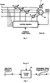
- Fig. 1 shows a schematic representation of a prior art heating system 8 which is a type of system for which parameters thereof such as the time delay parameter may be identified with the use of a parameter identification tool to which the invention pertains.
- the illustrated heating system comprises a heating plant 10 such as a gas furnace, at least one enclosure 12 to be heated by the furnace, and conduit means 14 for conveying a heated gas or liquid from the furnace to the enclosure.
- Fig. 2 shows a prior art type closed loop temperature control system 20 for controlling the temperature of the enclosure 12.
- the control system 20 has a thermostat 22 and an on/off type switch 24 in the loop with the heating plant 10.
- a heating system 8 can be approximated with a first order process with delay which includes a number of operating parameters including a time constant ⁇ p , a process gain K p and a time delay ⁇ .
- the time constant ⁇ p which may be on the order of 10 to 200 seconds, relates to the rate at which the enclosure 12 is heated and depends primarily on the sizes of the heating plant 10 and the characteristics of the enclosure.
- the process gain K p may be on the order of 0.5 to 1.5, which is the ratio of process output to process input at steady state.
- the delay ⁇ which may be on the order of 0 to 500 seconds, relates to the transport time of the heating medium in the conduit means 14 as it flows from the heating plant 10 to the enclosure 12 and depends mainly on the length and flow resistance of the conduit means 14.
- the controller 20 of Fig. 2 will not be appropriate because erratic operation will occur by reason of the controller not being responsive to the time delay parameter. What would happen is that there would be a lagging effect wherein the heated medium would not reach the enclosure until a substantial time after the thermostat begins calling for heat. After the desired temperature is reached, the plant 10 would be turned off but thereafter there would be an overshoot of the set point temperature wherein the heated medium (air, for example) would continue to be supplied to the enclosure. This would cause overheating.
- a preferred model is a three-layer feed-forward network 30 as shown in Fig. 3 and a preferred learning rule is the back-propagation learning rule.
- Back-propagation is a supervised learning procedure for feed-forward networks wherein training examples provided to the network indicate the desired network output or target for each example input.
- Feed-forward networks as used with back-propagation, comprise an input layer of processing units 32, zero or more hidden layers of processing units 33, and an output layer which may have only one processing unit 36.
- the output processing unit 36 outputs the process delay value ⁇ computed by the network 30. All the processing units output real values.
- the back-propagation learning technique performs gradient descent in a quadratic error measure to modify network weights.
- Fig. 3 is an example of a three-layer network 30 with one output unit.
- ⁇ j is defined differently for output and hidden units.
- ⁇ j o j ′(t j -o j ) where o j ′ is the derivative of o j with respect to its net input (for the activation function of Eq. (2), this quantity is o j (l-o j )) and t j is the target value (the "desired output") for unit j.
- the target value is not known and the error term is computed from the error terms of the next "higher" layer:
- Fig. 4 shows a prior art adaline type processing element which could be the general design for the hidden and output processing elements 33 and 36 of the network of Fig. 3.
- the processing element 36 has a series of trainable weights w l to w n with a threshold or bias weight b being connected to a fixed input of +1.
- Fig. 4 shows an arrangement for an output processing element whore the desired or target output pursuant to equation (4) is available for the learning algorithm.
- the arrangement for hidden units for which the desired or target output is not available is pursuant to equation (5).
- a mathematical model of a system containing one or more parameters, is necessary (Fig. 1). It is assumed that the processes for which the system identification tool is intended can be modeled with appropriate accuracy for the intended use by the mathematical model, for some specific assignments of the model parameters. It is also assumed that ranges for all model parameters can be specified. This assumption is not expected to pose practical problems, since extremely broad ranges can be used. Even it some parameter value that may be encountered are excluded, the robustness properties of neural networks render it likely that any resulting loss of accuracy will be small. In simple cases, or when little is known about the target processes, a range can consist of a lower limit and an upper limit, and all values within the range can be considered equally probable. In more complex cases and when adequate process knowledge exists, the ranges can be more sophisticated--the probability distribution over the range need not be uniform, or even unimodal.
- the tool and method development herein is based on a neural network approach having a two phase procedure.
- a mathematical model of the systems shown in Fig. 1 is utilized for generating training data.
- the mathematical model is implemented as a computer program.
- the training data comprises examples of open loop responses to a step input given to the system model. (Equivalent procedures with impulse or ramp input functions, or even arbitrary input functions, could also be utilized.)
- Each example is generated with a unique set of parameter values, each value within the set being chosen from the range specified for the parameter.
- the training data is applied in a teaching or learning mode to a neural network of an appropriate type, such as the network 30, to transform or convert the network into a tool for identifying at least one of the parameters such as the time delay parameter ⁇ .
- the learning rule is "supervised” learning in which it is assumed that the “desired output” for every training input is known.
- Supervised learning can be used to train an appropriately configured neural network such as network 30 for some specific task by providing examples of desired behavior.
- neural network based system identification is illustrated herein as being embodied in a prototype delay identification tool 30. More specifically, it is a neural network delay identifier for the open loop estimation of process delays for a linear first order process model.
- the modeling equation may be a linear or nonlinear differential equation, or an algebraic polynomial equation, within the scope of the invention.
- training examples are generated using a process model 40 as shown in Fig. 5.
- the process model with its parameters assigned to values within predetermined ranges, is given a step input S.
- the process temperature response output R or x(t) is sampled at some predetermined rate and the resulting real valued vector and the respective values of the time delay ⁇ are used as the training input for the neural network 30 as shown in Fig. 6.
- Fig. 6 designates a process input S, it will be understood that such input may be omitted in cases where S is a constant because it would only be varying values of S that would affect the output of the neural network.
- Identification is in terms of samples, not absolute units of time. By changing the sampling rate, the range of delays that can be identified (by the same trained network) can be controlled. If the minimum delay is known to be n seconds, sampling may start n seconds after the step input is given. The desired network output would then be ⁇ -n and n would be added to the output of the trained network to obtain the estimated process delay.
- the training data for the network 30 consisted of 6,000,000 dynamically generated examples.
- the ranges of parameters considered were ⁇ p from 10 to 200 seconds; ⁇ from 0 to 500 seconds; and K p from 0.5 to 1.5. Uniform distributions were used for all ranges.
- Training on a range of K p values is not strictly necessary it the correct value is available in operation.
- the process model is linear, the process output can easily be normalized.
- the noise in training inputs was gaussian with 99% (3 standard deviations) falling within ⁇ 5% of the range of process output values, which was normalized between 0 and 1.
- the output of the process was sampled every 10 seconds after the step input was given. 50 samples were collected and used as input to the network.
- each vector of 50 samples had one set of values of the parameters ⁇ p , ⁇ and K p associated with it.
- each such vector of 50 samples had the respective value of the time delay ⁇ associated with it, which in each case was the target value for adjusting the weights of the network.
- the network 30 had 50 input units (one for each sample), 15 hidden units and 1 output unit (the delay estimate).
- the value of the learning rate parameter ⁇ was 0.1 for the first 1,000,000 training iterations, and 0.01 thereafter.
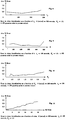
- the network 30 was tested on new (also randomly generated) data. Tests were performed to determine the effectiveness of delay identification as a function of delay, as a function of ⁇ p , and a function of K p , and as a function of the amount of noise.
- a noise figure of, say, 5 percent implies that 99 percent of the gaussian noise ( ⁇ 3 standard deviations) was within ⁇ 5 percent of the range of process output for that simulation.
- FIGS 8 through 11 depict the results of various tests. Each of these graphs shows the estimation error over a range of values of a particular parameter. The remaining parameters were held constant at or near the midpoints of their ranges.
- the network 30 After the network 30 has been trained, it can be used for on-line delay identification.
- the input to the network is now actual (not simulated) process output but the output of the network is again a delay estimate.
- This delay estimate can then be used for control and/or diagnostics. For example, it the process controller incorporates a Smith Predictor or other delay compensation technique, the delay estimate can be given as input to it.
- Fig. 7 depicts how delay identifier 50 embodying the network 30 can be applied to a unit 52 which comprises a PID controller having an associated Smith Predictor.
- the control loop is broken via a switch 54 and a (small) step input perturbation is applied to a process 56 thereof being controlled, by unit 52, via step input generator 58.
- the response of the process 56 to the perturbation is sampled and stored in a butter 60.
- the vector of samples (scaled appropriately) is used as input to the trained neural network 30.
- the output of the network is subjected to some post processing (scaling and/or translation) in a post processor 62 to obtain a delay estimate ⁇ est .
- switch 54 may be closed again and the process put back under closed loop control.
- the process delay is just one process parameter. Although estimates of time constants, gains, etc. are also required for control, it has been found that the process delay is the most critical parameter. Significant over or under estimates in process delay can cause worse control than proportionately poor estimates in the process time constant or the process gain.
- the approach herein for developing system identification tools is extremely general-purpose. It can be used for closed loop or open loop identification, for estimating any and all model parameters, and for linear and non-linear process models. For specific applications, simplification may be possible.
- the identification technique is an open loop one, the input perturbation can be identical for all training examples. It then need not be provided as input to the network 30. The constraint this imposes is that the same input perturbation, or (if the process model is linear) a scaled version of it, must be used during the operation.
- the essence of the invention is the approximation of a function from process input/output to parameter value estimates.
- estimates have to be produced given continuously (and unpredictably) varying inputs.
- neural network have been used to approximate functions as complex as chaotic time series.
- a simulation of the process under closed loop control could be used.
Abstract
Description
- The invention relates to a neural network tool for process system identification and a method for making the tool.
- The invention relates more specifically to a general purpose approach for process system identification. System identification is viewed as a function approximation problem, where the inputs to the function are the input and output of the process, and the outputs of the function are estimates of model parameters. This approach, which requires no mathematical analysis, utilizes the learning capabilities of neural networks, and can be used for a wide variety of applications.
- The identification of model parameters for an unknown or incompletely known process system is important for both control and diagnosis. The more accurately a plant or process can be identified, the better it can be controlled. Estimates of system parameters are an essential aspect of adaptive/predictive control and auto-tuning. In addition, changes in system parameters can be valuable diagnostic indicators. A sudden increase in the delay of a transport process, for example, could imply a blocked pipe.
- System identification is the object of extensive research in control theory and a number of techniques have been developed. Most current approaches to system identification can be characterized as hard knowledge approaches derived through extensive mathematical analysis.
- A shortcoming of many current system identification approaches is that the assumptions necessary to facilitate the mathematical analysis for a particular application may not be valid for other applications.
- A main object of the invention herein is to provide a system identification tool having generality of application. Under this concept, a general purpose technique can be used for a large variety of system identification problems with little or no mathematical effort required. In many applications the short development time that a general purpose technique would allow while still satisfying performance requirements would be a significant advantage.
- In recent years, advances in the field of neural networks have produced learning rules for developing arbitrary non-linear multidimensional real-valued mappings. These learning rules operate on examples of the desired functionality and no programming is required. The simplicity of neural network computational models is also an advantage.
- System identification is an extensively researched area of control theory with innumerable applications. When the purpose of the identification is to design a control system, the character of the problem might vary widely depending on the nature of the control problem. In some cases it might be sufficient to have a fairly crude model of the system dynamics. Other cases might require a fairly accurate model of the system dynamics or even a model of the environment of the system.
- In most practical problems there is seldom sufficient a priori information about a system and its environment to design a control system from this information alone. It will thus often be necessary to make some kind of experiment involving using perturbations as input signals and observing the corresponding changes in process variables.
- A neural network of the type utilized by the invention herein in constructed from two primitive elements which are processing units and directed connections between the processing units. The processing units are densely interconnected with each connection typically having a real valued weight associated with it which determines the effect of the source unit on the destination unit. The output of a processing unit is some function of the weighted sum of its inputs:

where oj is the output of unit j, wij is the weight from unit i to unit j, and bj is the "threshold" or bias weight for unit j. The quantity
is usually referred to as the net input to unit j, symbolized netj. - Processing units are often arranged in layers. In many applications the networks are constrained to be acyclic and the connections are constrained to lie between adjacent layers. A multilayer feed forward network of this type can realize any mapping from a multidimensional continuous input space to a multidimensional continuous output space with arbitrarily high accuracy.
- Many continuous processes have process delays generally due to transport of fluids. In these processes a conventional feedback controller would provide unsatisfactory closed-loop response. A controller which can compensate for delay is required to achieve good control of the process. Delay compensation techniques, such as the Smith Predictor (an example of which can be found in the work of Stephanopoulos, G. (1984); Chemical Process Control: An Introduction to Theory and Practice; Prentice Hall Publishers) require estimates of the process delay.
- A further object of the invention herein is to provide a new technique for process delay identification which is an open loop identification technique based on a learning neural network approach.
- Existing techniques for delay identification are based on extensive mathematical analyses. A major advantage of the technique herein is that it uses a general purpose neural network learning architecture for which no mathematical analysis of the problem is needed before implementing a neural network delay identifier.
- Other objects and advantages of the invention will become apparent from the following specification, appended claims, and attached drawings.
- In the drawings:
- Fig. 1 shows a schematic representation of a prior art type heating system for which parameters thereof, such as the time delay parameter, may be identified with the use of the parameter identification tool of the present invention;
- Fig. 2 shows a prior art type closed-loop temperature control system for controlling the temperature of the heating system of Fig. 1;
- Fig. 3 is a schematic diagram illustrating a neural network which can be trained in accordance with the invention to be used as a system identification tool;
- Fig. 4 is a block diagram showing a prior art adaline type of processing element which may be used for the neural network of Fig. 3;
- Fig. 5 is a block diagram illustrating an arrangement for using a process model for generating training examples for training the network shown in Fig. 3;
- Fig. 6 is a block diagram showing an arrangement for using training examples to train the network of Fig. 3;
- Fig. 7 is a block diagram showing the use of a neural network which has been trained to function as a system identification tool for the time delay identification of a process:
- Fig. 8 is a graph showing error in delay identification as a function of τp;
- Fig. 9 is a graph illustrating error in delay identifications as a function of ϑ;
- Fig.10 is a graph of error in delay identification as a function of Kp; and
- Fig. 11 is a graph of error in delay identification as a function of noise.
- With reference to the drawings, Fig. 1 shows a schematic representation of a prior
art heating system 8 which is a type of system for which parameters thereof such as the time delay parameter may be identified with the use of a parameter identification tool to which the invention pertains. The illustrated heating system comprises aheating plant 10 such as a gas furnace, at least oneenclosure 12 to be heated by the furnace, and conduit means 14 for conveying a heated gas or liquid from the furnace to the enclosure. - Fig. 2 shows a prior art type closed loop
temperature control system 20 for controlling the temperature of theenclosure 12. Thecontrol system 20 has athermostat 22 and an on/offtype switch 24 in the loop with theheating plant 10. - A
heating system 8 can be approximated with a first order process with delay which includes a number of operating parameters including a time constant τp, a process gain Kp and a time delay ϑ. - The time constant τp, which may be on the order of 10 to 200 seconds, relates to the rate at which the
enclosure 12 is heated and depends primarily on the sizes of theheating plant 10 and the characteristics of the enclosure. - The process gain Kp may be on the order of 0.5 to 1.5, which is the ratio of process output to process input at steady state.
- The delay ϑ, which may be on the order of 0 to 500 seconds, relates to the transport time of the heating medium in the conduit means 14 as it flows from the
heating plant 10 to theenclosure 12 and depends mainly on the length and flow resistance of the conduit means 14. - In certain installations in which the time delay parameter ϑ of the conduit means 14 is relatively large, the
controller 20 of Fig. 2 will not be appropriate because erratic operation will occur by reason of the controller not being responsive to the time delay parameter. What would happen is that there would be a lagging effect wherein the heated medium would not reach the enclosure until a substantial time after the thermostat begins calling for heat. After the desired temperature is reached, theplant 10 would be turned off but thereafter there would be an overshoot of the set point temperature wherein the heated medium (air, for example) would continue to be supplied to the enclosure. This would cause overheating. - There are a number of neural network models and learning rules that can be used for implementing the invention. A preferred model is a three-layer feed-
forward network 30 as shown in Fig. 3 and a preferred learning rule is the back-propagation learning rule. Back-propagation is a supervised learning procedure for feed-forward networks wherein training examples provided to the network indicate the desired network output or target for each example input. - Feed-forward networks, as used with back-propagation, comprise an input layer of
processing units 32, zero or more hidden layers ofprocessing units 33, and an output layer which may have only oneprocessing unit 36. In the illustrated embodiment theoutput processing unit 36 outputs the process delay value ϑ computed by thenetwork 30. All the processing units output real values. - The back-propagation learning technique performs gradient descent in a quadratic error measure to modify network weights. The form of Eq. (1) that is usually employed with back-propagation is the sigmoid function:

- Back-propagation is usually used with multilayer feed-forward networks of the type shown in Fig. 3 which is an example of a three-
layer network 30 with one output unit. - The rule used to modify the weights may be:


- Fig. 4 shows a prior art adaline type processing element which could be the general design for the hidden and
output processing elements processing element 36 has a series of trainable weights wl to wn with a threshold or bias weight b being connected to a fixed input of +1. - Fig. 4 shows an arrangement for an output processing element whore the desired or target output pursuant to equation (4) is available for the learning algorithm. The arrangement for hidden units for which the desired or target output is not available is pursuant to equation (5).
- For the exercise of this invention, a mathematical model of a system, containing one or more parameters, is necessary (Fig. 1). It is assumed that the processes for which the system identification tool is intended can be modeled with appropriate accuracy for the intended use by the mathematical model, for some specific assignments of the model parameters. It is also assumed that ranges for all model parameters can be specified. This assumption is not expected to pose practical problems, since extremely broad ranges can be used. Even it some parameter value that may be encountered are excluded, the robustness properties of neural networks render it likely that any resulting loss of accuracy will be small. In simple cases, or when little is known about the target processes, a range can consist of a lower limit and an upper limit, and all values within the range can be considered equally probable. In more complex cases and when adequate process knowledge exists, the ranges can be more sophisticated--the probability distribution over the range need not be uniform, or even unimodal.
- The tool and method development herein is based on a neural network approach having a two phase procedure. In the first phase a mathematical model of the systems shown in Fig. 1 is utilized for generating training data. The mathematical model is implemented as a computer program. The training data comprises examples of open loop responses to a step input given to the system model. (Equivalent procedures with impulse or ramp input functions, or even arbitrary input functions, could also be utilized.) Each example is generated with a unique set of parameter values, each value within the set being chosen from the range specified for the parameter.
- In the second phase the training data is applied in a teaching or learning mode to a neural network of an appropriate type, such as the
network 30, to transform or convert the network into a tool for identifying at least one of the parameters such as the time delay parameter ϑ. - With reference to the second phase, the learning rule is "supervised" learning in which it is assumed that the "desired output" for every training input is known. Supervised learning can be used to train an appropriately configured neural network such as
network 30 for some specific task by providing examples of desired behavior. - The concept of neural network based system identification is illustrated herein as being embodied in a prototype
delay identification tool 30. More specifically, it is a neural network delay identifier for the open loop estimation of process delays for a linear first order process model. - The system shown in Fig. 1 may be modeled as a linear first order process with delay by the equation:

enclosure 12, τp is the time constant of the process, Kp is the process gain, and ϑ is the process delay. Kp, τp and ϑ are the parameters of the model. - The modeling equation may be a linear or nonlinear differential equation, or an algebraic polynomial equation, within the scope of the invention.
- In the first phase referred to above, training examples are generated using a
process model 40 as shown in Fig. 5. The process model, with its parameters assigned to values within predetermined ranges, is given a step input S. The process temperature response output R or x(t) is sampled at some predetermined rate and the resulting real valued vector and the respective values of the time delay ϑ are used as the training input for theneural network 30 as shown in Fig. 6. - Although Fig. 6 designates a process input S, it will be understood that such input may be omitted in cases where S is a constant because it would only be varying values of S that would affect the output of the neural network.
- Identification is in terms of samples, not absolute units of time. By changing the sampling rate, the range of delays that can be identified (by the same trained network) can be controlled. If the minimum delay is known to be n seconds, sampling may start n seconds after the step input is given. The desired network output would then be ϑ-n and n would be added to the output of the trained network to obtain the estimated process delay.
- Numerous situations of training and operation to evaluate the system have been run. Our simulations fall into two classes. First, we have investigated the error of delay estimation over wide ranges of process parameters. Second, we have simulated the set-up of Fig. 7 and demonstrated the improved control that can be achieved using our delay identifier. The results described below employed a three-layer network with 15 hidden units.
- In one such simulation the training data for the
network 30 consisted of 6,000,000 dynamically generated examples. The ranges of parameters considered were τp from 10 to 200 seconds; ϑ from 0 to 500 seconds; and Kp from 0.5 to 1.5. Uniform distributions were used for all ranges. - Training on a range of Kp values is not strictly necessary it the correct value is available in operation. As the process model is linear, the process output can easily be normalized. However, without training on a range of Kp, even small changes in the value of this parameter can result in significant error in delay estimation. The noise in training inputs was gaussian with 99% (3 standard deviations) falling within ± 5% of the range of process output values, which was normalized between 0 and 1. The output of the process was sampled every 10 seconds after the step input was given. 50 samples were collected and used as input to the network.
- During the generation of training data via
process model 40, each vector of 50 samples had one set of values of the parameters τp, ϑ and Kp associated with it. During the training of thenetwork 30, each such vector of 50 samples had the respective value of the time delay ϑ associated with it, which in each case was the target value for adjusting the weights of the network. - The
network 30 had 50 input units (one for each sample), 15 hidden units and 1 output unit (the delay estimate). The value of the learning rate parameter η was 0.1 for the first 1,000,000 training iterations, and 0.01 thereafter. - After training, the
network 30 was tested on new (also randomly generated) data. Tests were performed to determine the effectiveness of delay identification as a function of delay, as a function of τp, and a function of Kp, and as a function of the amount of noise. A noise figure of, say, 5 percent implies that 99 percent of the gaussian noise (± 3 standard deviations) was within ± 5 percent of the range of process output for that simulation. - Figures 8 through 11 depict the results of various tests. Each of these graphs shows the estimation error over a range of values of a particular parameter. The remaining parameters were held constant at or near the midpoints of their ranges.
- Based on these tests, the following observations were made:
- . The average estimation error is within 2.5 percent over a wide range of delays and process time constants for realistic amounts of noise.
- . For parameter values within training ranges, estimation error is small. There is one major exception. For very small delays, percentage error is large. This is to be expected. The sampled process output in this case provides little relevant data. It is likely that a non-uniform sampling range would overcome this problem.
- . In many cases, estimation error is acceptable even for parameter values outside training ranges. For example, the average error for τp = 280 less than 4%. Even for gains twice as high as any the network was trained on, the average error in around 4%.
- . Estimation is robust with respect to noise. For 25% noise, the average error is about 6.5%.
- After the
network 30 has been trained, it can be used for on-line delay identification. The input to the network is now actual (not simulated) process output but the output of the network is again a delay estimate. This delay estimate can then be used for control and/or diagnostics. For example, it the process controller incorporates a Smith Predictor or other delay compensation technique, the delay estimate can be given as input to it. - Fig. 7 depicts how
delay identifier 50 embodying thenetwork 30 can be applied to aunit 52 which comprises a PID controller having an associated Smith Predictor. When a delay estimate is needed, the control loop is broken via aswitch 54 and a (small) step input perturbation is applied to aprocess 56 thereof being controlled, byunit 52, viastep input generator 58. The response of theprocess 56 to the perturbation is sampled and stored in abutter 60. When a sufficient number of samples have been received, the vector of samples (scaled appropriately) is used as input to the trainedneural network 30. The output of the network is subjected to some post processing (scaling and/or translation) in apost processor 62 to obtain a delay estimate ϑest. Once the delay estimate has been input to the Smith Predictor, switch 54 may be closed again and the process put back under closed loop control. - A simulated set-up of Fig. 7 has been utilized to investigate the effect on closed loop control of delay identification. A first order process and a simple proportional controller were used for the simulation. It was found that signiticantly better control is achieved with a good knowledge of the process delay.
- The process delay is just one process parameter. Although estimates of time constants, gains, etc. are also required for control, it has been found that the process delay is the most critical parameter. Significant over or under estimates in process delay can cause worse control than proportionately poor estimates in the process time constant or the process gain.
- The approach herein for developing system identification tools is extremely general-purpose. It can be used for closed loop or open loop identification, for estimating any and all model parameters, and for linear and non-linear process models. For specific applications, simplification may be possible. For example, it the identification technique is an open loop one, the input perturbation can be identical for all training examples. It then need not be provided as input to the
network 30. The constraint this imposes is that the same input perturbation, or (if the process model is linear) a scaled version of it, must be used during the operation. - The description of the invention herein has for the most part been directed to open loop system identification. That is, it is assumed that an input can be given to the process and its response observed without the confounding effects of feedback. A simplified but realistic form of closed loop delay identification has also been considered, however.
- The essence of the invention is the approximation of a function from process input/output to parameter value estimates. For general closed loop identification, estimates have to be produced given continuously (and unpredictably) varying inputs. In principle, there appears to be no reason why a network could not be trained for this case as well; neural network have been used to approximate functions as complex as chaotic time series. A simulation of the process under closed loop control could be used.
- We have investigated a constrained form of closed-loop identification: delay identification under "bang-bang" control. In closed-loop bang-bang control, the process can be switched on or off. Whenever the output exceeds an upper bound, the process is turned off; whenever the output falls below a lower bound, the process is turned on. Bang-bang control is commonly used when highly accurate control is not required - e.g., in HVAC systems.
- For delay identification under bang-bang control, we assume that the collection of output samples is initiated when the process is turned on. After the predetermined number of samples have been collected, an estimate is produced. Given this scenario, there is only one significant difference between open-loop and bang-bang delay identification: In the former case, the process is assumed to be at a constant value (except for noise) from when the step input is given until the delay expires; in the bang-bang case, the process output is decaying during the delay. The decaying and rising responses can be governed by different dynamics.
- We have trained a network to identify the delay of a process under bang-bang control. It was assumed that both the "on" process and the "off" process were first-order with independent (and therefore different) time constants. The process input was again constant over the duration of a training example and was not provided to the network. An average error rate of around 7% was achieved in 100,000 iterations. The network converges significantly faster than for the open-loop delay identification, and we expect that a comparably long simulation would produce lower error rates. The better performance in the bang-bang closed-loop case is not too surprising: a transition between falling and rising curves is easier to detect than a transition between constant and rising curves.
Claims (23)
- A method for developing a tool for identifying at least one parameter of a process which is modelled by an equation having m parameters p₁, p₂,...pm; the method characterised by the steps:
determining ranges for each of said m parameters;
modelling said equation via a computer program;
utilizing said program to generate a set of training examples, each of said examples having (1) selected values of said parameters from within said respective ranges and (2) process output data resulting from said program when said selected values of said parameters are used; and
using said set of training examples to train an artificial neural network such that (1) the input to said network comprises for each of said training examples respective values of at least said process output data and (2) the output of said network comprises respectively for each of said training examples at least one of said selected values of said parameters. - A method according to Claim 1 characterised in that said equation is a linear differential equation.
- A method according to Claim 1 characterised in that said equation is a nonlinear differential equation.
- A method according to any preceding Claim characterised in that said equation is an algebraic polynomial equation with said parameters being represented as coefficients.
- A method according to any preceding Claim characterised in that each of said training examples includes input data employed in said program for said selected values of said parameters.
- A method according to Claim 5 characterised in that said input to said network includes varying values of said input data.
- A method according to any preceding Claim characterised in that said equation has the form:

- A method for making a neural network tool for identifying parameters of a system which may be modelled by the equation:

providing a neural network having an arrangement of processing elements and adjustable weights connecting the outputs of some of said elements to the inputs of other of said elements, said network having input and output terminal means and target setting terminal means;
providing learning algorithm operational means for said network for adjusting said weights wherein output values on said output terminal means are biased to converge respectively to target values applied to said target setting terminal means;
making a model of said equation and utilizing said model to generate sets of training data for said neural network with each of said sets having selected values of said parameters within respective predetermined ranges and a resulting response which is said x(t); and
sequentially applying said sets of training data to said neural network with each of said sets having said response thereof applied to said input terminal means and said values of said parameters beings applied to said target setting terminal means. - A method according to Claim 8 characterised in that said system is a linear first order system.
- A method according to Claim 8 or 9 characterised in that each of said sets applied to said network has only one of said parameters applied to said target setting terminal means.
- A method according to claim 10 characterised in that said one of said parameters is said system delay parameter.
- A method according to any of Claims 8 to 11 characterised in that each of said sets of training data includes a stimulus value for said model which is applied to said input terminal means of said network.
- A method according to Claim 12 characterized in that said stimulus value is a step input.
- Apparatus for developing a tool for identifying at least one parameter of a process which is modelled by an equation having m parameters p₁, p₂,...pm; the apparatus characterised by:
means to determine ranges for each of said m parameters;
means to model said equation via a computer program;
means to utilize said program to generate a set of training examples, each of said examples having (1) selected values of said parameters from within said respective ranges and (2) process output data resulting from said program when said selected values of said parameters are used; and means to use said set of training examples to train an artificial neural network such that (1) the input to said network comprises for each of said training examples respective values of at least said process output data and (2) the output of said network comprises respectively for each said training examples at least one of said selected values of said parameters. - Apparatus according to Claim 14 characterised in that each of said training examples includes input data employed in said program for said selected values of said parameters.
- Apparatus according to Claim 15 characterised in that said input to said network includes varying values of said input data.
- Apparatus according to any of Claims 14 to 16 characterised in that said equation has the form:

- Apparatus for making a neural network tool for identifying parameters of a system which may be modelled by the equation:

means to provide a neural network having an arrangement of processing elements and adjustable weights connecting the outputs of some of said elements to the inputs of other of said elements, said network having input and output terminal means and target setting terminal means;
learning algorithm operational means for said network for adjusting said weights wherein output values on said output terminal means are biased to converge respectively to target values applied to said target setting terminal means;
means to make a model of said equation and utilizing said model to generate sets of training data for said neural network with each of said sets having selected values of said parameters within respective predetermined ranges and a resulting response which is said x(t); and
means to sequentially apply said sets of training data to said neural network with each of said sets having said response thereof applied to said input terminal means and said values of said parameters beings applied to said target setting terminal means. - Apparatus according to Claim 18 characterised in that each of said sets applied to said network has only one said parameters applied to said target setting terminal means.
- Apparatus according to Claims 18 or 19 characterised in that said one of said parameters is said system delay parameter ϑ.
- Apparatus according to any of Claims 18 to 20 characterised in that each of said sets of training data includes a stimulus value for said model which is applied to said input terminal means of said network.
- A tool developed as the product of a method according to any of Claims 1 to 13 and/or as the product of apparatus according to any of Claims 14 to 21.
- A control system developed as the product of a method according to any of Claims 1 to 13 and/or as the product of apparatus according to any of Claims 14 to 21.
Applications Claiming Priority (2)
| Application Number | Priority Date | Filing Date | Title |
|---|---|---|---|
| US59492790A | 1990-10-10 | 1990-10-10 | |
| US594927 | 1990-10-10 |
Publications (3)
| Publication Number | Publication Date |
|---|---|
| EP0480654A2 true EP0480654A2 (en) | 1992-04-15 |
| EP0480654A3 EP0480654A3 (en) | 1993-04-14 |
| EP0480654B1 EP0480654B1 (en) | 1998-03-04 |
Family
ID=24380998
Family Applications (1)
| Application Number | Title | Priority Date | Filing Date |
|---|---|---|---|
| EP91309163A Expired - Lifetime EP0480654B1 (en) | 1990-10-10 | 1991-10-07 | Process system identification |
Country Status (7)
| Country | Link |
|---|---|
| US (2) | US5740324A (en) |
| EP (1) | EP0480654B1 (en) |
| JP (1) | JPH0628007A (en) |
| AT (1) | ATE163777T1 (en) |
| CA (1) | CA2053056A1 (en) |
| DE (1) | DE69128996T2 (en) |
| ES (1) | ES2112853T3 (en) |
Cited By (3)
| Publication number | Priority date | Publication date | Assignee | Title |
|---|---|---|---|---|
| EP0496570A2 (en) * | 1991-01-22 | 1992-07-29 | Honeywell Inc. | Two-level system identifier apparatus with optimization |
| DE19729187C1 (en) * | 1997-07-08 | 1999-04-29 | Siemens Ag | Function simulator, e.g. a neural net used in process control, is quality tested |
| DE4338607B4 (en) * | 1993-11-11 | 2005-10-06 | Siemens Ag | Method and device for managing a process in a controlled system |
Families Citing this family (120)
| Publication number | Priority date | Publication date | Assignee | Title |
|---|---|---|---|---|
| JPH07335552A (en) * | 1994-06-08 | 1995-12-22 | Tel Varian Ltd | Treatment device |
| US5659666A (en) * | 1994-10-13 | 1997-08-19 | Thaler; Stephen L. | Device for the autonomous generation of useful information |
| US6092919A (en) * | 1995-08-01 | 2000-07-25 | Guided Systems Technologies, Inc. | System and method for adaptive control of uncertain nonlinear processes |
| US7949495B2 (en) | 1996-03-28 | 2011-05-24 | Rosemount, Inc. | Process variable transmitter with diagnostics |
| US6654697B1 (en) | 1996-03-28 | 2003-11-25 | Rosemount Inc. | Flow measurement with diagnostics |
| US6017143A (en) | 1996-03-28 | 2000-01-25 | Rosemount Inc. | Device in a process system for detecting events |
| US6539267B1 (en) | 1996-03-28 | 2003-03-25 | Rosemount Inc. | Device in a process system for determining statistical parameter |
| US8290721B2 (en) | 1996-03-28 | 2012-10-16 | Rosemount Inc. | Flow measurement diagnostics |
| US6434504B1 (en) | 1996-11-07 | 2002-08-13 | Rosemount Inc. | Resistance based process control device diagnostics |
| US6519546B1 (en) | 1996-11-07 | 2003-02-11 | Rosemount Inc. | Auto correcting temperature transmitter with resistance based sensor |
| US6449574B1 (en) | 1996-11-07 | 2002-09-10 | Micro Motion, Inc. | Resistance based process control device diagnostics |
| US6754601B1 (en) | 1996-11-07 | 2004-06-22 | Rosemount Inc. | Diagnostics for resistive elements of process devices |
| US6601005B1 (en) | 1996-11-07 | 2003-07-29 | Rosemount Inc. | Process device diagnostics using process variable sensor signal |
| DE69714606T9 (en) * | 1996-12-31 | 2004-09-09 | Rosemount Inc., Eden Prairie | DEVICE FOR CHECKING A CONTROL SIGNAL COMING FROM A PLANT IN A PROCESS CONTROL |
| DE69818494T2 (en) | 1997-10-13 | 2004-07-01 | Rosemount Inc., Eden Prairie | Transmission method for field devices in industrial processes |
| US6556980B1 (en) * | 1998-08-28 | 2003-04-29 | General Cyberation Group, Inc. | Model-free adaptive control for industrial processes |
| US6415272B1 (en) * | 1998-10-22 | 2002-07-02 | Yamaha Hatsudoki Kabushiki Kaisha | System for intelligent control based on soft computing |
| US6611775B1 (en) | 1998-12-10 | 2003-08-26 | Rosemount Inc. | Electrode leakage diagnostics in a magnetic flow meter |
| US6615149B1 (en) | 1998-12-10 | 2003-09-02 | Rosemount Inc. | Spectral diagnostics in a magnetic flow meter |
| US6975219B2 (en) * | 2001-03-01 | 2005-12-13 | Fisher-Rosemount Systems, Inc. | Enhanced hart device alerts in a process control system |
| US8044793B2 (en) | 2001-03-01 | 2011-10-25 | Fisher-Rosemount Systems, Inc. | Integrated device alerts in a process control system |
| US6356191B1 (en) | 1999-06-17 | 2002-03-12 | Rosemount Inc. | Error compensation for a process fluid temperature transmitter |
| DE60014709T3 (en) | 1999-07-01 | 2010-04-15 | Rosemount Inc., Eden Prairie | TWO-WIRE TRANSMITTER WITH SELF-TESTING AND LOW POWER |
| US6505517B1 (en) | 1999-07-23 | 2003-01-14 | Rosemount Inc. | High accuracy signal processing for magnetic flowmeter |
| US6505475B1 (en) | 1999-08-20 | 2003-01-14 | Hudson Technologies Inc. | Method and apparatus for measuring and improving efficiency in refrigeration systems |
| US6701274B1 (en) | 1999-08-27 | 2004-03-02 | Rosemount Inc. | Prediction of error magnitude in a pressure transmitter |
| US6556145B1 (en) | 1999-09-24 | 2003-04-29 | Rosemount Inc. | Two-wire fluid temperature transmitter with thermocouple diagnostics |
| US6684112B1 (en) * | 2000-04-11 | 2004-01-27 | George Shu-Xing Cheng | Robust model-free adaptive control |
| JP4918207B2 (en) * | 2000-06-29 | 2012-04-18 | アスペン テクノロジー インコーポレイテッド | Computer system and method for constraining nonlinear approximation of empirical processes. |
| US6701193B1 (en) * | 2000-08-18 | 2004-03-02 | Ford Motor Company | Method of adaptively controlling paint system |
| US6735484B1 (en) | 2000-09-20 | 2004-05-11 | Fargo Electronics, Inc. | Printer with a process diagnostics system for detecting events |
| FR2818742B1 (en) * | 2000-12-22 | 2003-02-14 | Inst Francais Du Petrole | METHOD FOR FORMING AN OPTIMIZED NEURAL NETWORK MODULE FOR SIMULATING THE FLOW MODE OF A POLYPHASIC FLUID Vein |
| WO2002071171A2 (en) | 2001-03-01 | 2002-09-12 | Fisher-Rosemount Systems, Inc. | Automatic work order/parts order generation and tracking |
| US6954713B2 (en) * | 2001-03-01 | 2005-10-11 | Fisher-Rosemount Systems, Inc. | Cavitation detection in a process plant |
| US8073967B2 (en) | 2002-04-15 | 2011-12-06 | Fisher-Rosemount Systems, Inc. | Web services-based communications for use with process control systems |
| US6795798B2 (en) | 2001-03-01 | 2004-09-21 | Fisher-Rosemount Systems, Inc. | Remote analysis of process control plant data |
| US7389204B2 (en) * | 2001-03-01 | 2008-06-17 | Fisher-Rosemount Systems, Inc. | Data presentation system for abnormal situation prevention in a process plant |
| US7720727B2 (en) | 2001-03-01 | 2010-05-18 | Fisher-Rosemount Systems, Inc. | Economic calculations in process control system |
| US6629059B2 (en) | 2001-05-14 | 2003-09-30 | Fisher-Rosemount Systems, Inc. | Hand held diagnostic and communication device with automatic bus detection |
| US7162534B2 (en) * | 2001-07-10 | 2007-01-09 | Fisher-Rosemount Systems, Inc. | Transactional data communications for process control systems |
| US6772036B2 (en) | 2001-08-30 | 2004-08-03 | Fisher-Rosemount Systems, Inc. | Control system using process model |
| US7117045B2 (en) * | 2001-09-08 | 2006-10-03 | Colorado State University Research Foundation | Combined proportional plus integral (PI) and neural network (nN) controller |
| US6701236B2 (en) | 2001-10-19 | 2004-03-02 | Yamaha Hatsudoki Kabushiki Kaisha | Intelligent mechatronic control suspension system based on soft computing |
| KR100979071B1 (en) * | 2002-02-22 | 2010-08-31 | 에이저 시스템즈 인크 | Chemical mechanical polishing of dual orientation polycrystalline materials |
| NZ571299A (en) * | 2002-12-09 | 2010-01-29 | Hudson Technologies Inc | Method and apparatus for optimizing refrigeration systems |
| US8463441B2 (en) * | 2002-12-09 | 2013-06-11 | Hudson Technologies, Inc. | Method and apparatus for optimizing refrigeration systems |
| US7600234B2 (en) * | 2002-12-10 | 2009-10-06 | Fisher-Rosemount Systems, Inc. | Method for launching applications |
| US8935298B2 (en) | 2002-12-30 | 2015-01-13 | Fisher-Rosemount Systems, Inc. | Integrated navigational tree importation and generation in a process plant |
| US7493310B2 (en) | 2002-12-30 | 2009-02-17 | Fisher-Rosemount Systems, Inc. | Data visualization within an integrated asset data system for a process plant |
| US7152072B2 (en) | 2003-01-08 | 2006-12-19 | Fisher-Rosemount Systems Inc. | Methods and apparatus for importing device data into a database system used in a process plant |
| US20040158474A1 (en) * | 2003-02-06 | 2004-08-12 | Karschnia Robert J. | Service facility for providing remote diagnostic and maintenance services to a process plant |
| US7953842B2 (en) | 2003-02-19 | 2011-05-31 | Fisher-Rosemount Systems, Inc. | Open network-based data acquisition, aggregation and optimization for use with process control systems |
| US7103427B2 (en) | 2003-02-28 | 2006-09-05 | Fisher-Rosemont Systems, Inc. | Delivery of process plant notifications |
| US6915235B2 (en) * | 2003-03-13 | 2005-07-05 | Csi Technology, Inc. | Generation of data indicative of machine operational condition |
| US7634384B2 (en) * | 2003-03-18 | 2009-12-15 | Fisher-Rosemount Systems, Inc. | Asset optimization reporting in a process plant |
| US20040230328A1 (en) * | 2003-03-21 | 2004-11-18 | Steve Armstrong | Remote data visualization within an asset data system for a process plant |
| US7299415B2 (en) * | 2003-06-16 | 2007-11-20 | Fisher-Rosemount Systems, Inc. | Method and apparatus for providing help information in multiple formats |
| CA2496661C (en) * | 2004-02-19 | 2009-05-19 | Oz Optics Ltd. | Light source control system |
| US7030747B2 (en) * | 2004-02-26 | 2006-04-18 | Fisher-Rosemount Systems, Inc. | Method and system for integrated alarms in a process control system |
| US7079984B2 (en) * | 2004-03-03 | 2006-07-18 | Fisher-Rosemount Systems, Inc. | Abnormal situation prevention in a process plant |
| US7676287B2 (en) * | 2004-03-03 | 2010-03-09 | Fisher-Rosemount Systems, Inc. | Configuration system and method for abnormal situation prevention in a process plant |
| US7251638B2 (en) | 2004-03-03 | 2007-07-31 | Yamaha Hatsudoki Kabushiki Kaisha | Intelligent robust control system for motorcycle using soft computing optimizer |
| US7515977B2 (en) | 2004-03-30 | 2009-04-07 | Fisher-Rosemount Systems, Inc. | Integrated configuration system for use in a process plant |
| US20050267709A1 (en) * | 2004-05-28 | 2005-12-01 | Fisher-Rosemount Systems, Inc. | System and method for detecting an abnormal situation associated with a heater |
| US7536274B2 (en) * | 2004-05-28 | 2009-05-19 | Fisher-Rosemount Systems, Inc. | System and method for detecting an abnormal situation associated with a heater |
| CA2567139A1 (en) | 2004-06-12 | 2005-12-29 | Fisher-Rosemount Systems, Inc. | System and method for detecting an abnormal situation associated with a process gain of a control loop |
| US7181654B2 (en) * | 2004-09-17 | 2007-02-20 | Fisher-Rosemount Systems, Inc. | System and method for detecting an abnormal situation associated with a reactor |
| US20060224547A1 (en) * | 2005-03-24 | 2006-10-05 | Ulyanov Sergey V | Efficient simulation system of quantum algorithm gates on classical computer based on fast algorithm |
| US20060218108A1 (en) * | 2005-03-24 | 2006-09-28 | Sergey Panfilov | System for soft computing simulation |
| US9201420B2 (en) | 2005-04-08 | 2015-12-01 | Rosemount, Inc. | Method and apparatus for performing a function in a process plant using monitoring data with criticality evaluation data |
| US8005647B2 (en) | 2005-04-08 | 2011-08-23 | Rosemount, Inc. | Method and apparatus for monitoring and performing corrective measures in a process plant using monitoring data with corrective measures data |
| US8112565B2 (en) | 2005-06-08 | 2012-02-07 | Fisher-Rosemount Systems, Inc. | Multi-protocol field device interface with automatic bus detection |
| US20060293817A1 (en) * | 2005-06-23 | 2006-12-28 | Takahide Hagiwara | Intelligent electronically-controlled suspension system based on soft computing optimizer |
| US7272531B2 (en) * | 2005-09-20 | 2007-09-18 | Fisher-Rosemount Systems, Inc. | Aggregation of asset use indices within a process plant |
| US20070068225A1 (en) | 2005-09-29 | 2007-03-29 | Brown Gregory C | Leak detector for process valve |
| US7840287B2 (en) * | 2006-04-13 | 2010-11-23 | Fisher-Rosemount Systems, Inc. | Robust process model identification in model based control techniques |
| US8606544B2 (en) | 2006-07-25 | 2013-12-10 | Fisher-Rosemount Systems, Inc. | Methods and systems for detecting deviation of a process variable from expected values |
| US7657399B2 (en) * | 2006-07-25 | 2010-02-02 | Fisher-Rosemount Systems, Inc. | Methods and systems for detecting deviation of a process variable from expected values |
| US7912676B2 (en) * | 2006-07-25 | 2011-03-22 | Fisher-Rosemount Systems, Inc. | Method and system for detecting abnormal operation in a process plant |
| US8145358B2 (en) * | 2006-07-25 | 2012-03-27 | Fisher-Rosemount Systems, Inc. | Method and system for detecting abnormal operation of a level regulatory control loop |
| US7953501B2 (en) | 2006-09-25 | 2011-05-31 | Fisher-Rosemount Systems, Inc. | Industrial process control loop monitor |
| US8788070B2 (en) | 2006-09-26 | 2014-07-22 | Rosemount Inc. | Automatic field device service adviser |
| CN101535909B (en) * | 2006-09-28 | 2012-08-29 | 费舍-柔斯芒特系统股份有限公司 | Abnormal situation prevention in a heat exchanger |
| US7853431B2 (en) | 2006-09-29 | 2010-12-14 | Fisher-Rosemount Systems, Inc. | On-line monitoring and diagnostics of a process using multivariate statistical analysis |
| JP2010505121A (en) | 2006-09-29 | 2010-02-18 | ローズマウント インコーポレイテッド | Magnetic flow meter with verification |
| US20080188972A1 (en) * | 2006-10-11 | 2008-08-07 | Fisher-Rosemount Systems, Inc. | Method and System for Detecting Faults in a Process Plant |
| US20080147361A1 (en) * | 2006-12-15 | 2008-06-19 | Miller Daniel H | Methods and apparatus to monitor system health |
| US8032341B2 (en) * | 2007-01-04 | 2011-10-04 | Fisher-Rosemount Systems, Inc. | Modeling a process using a composite model comprising a plurality of regression models |
| US8032340B2 (en) | 2007-01-04 | 2011-10-04 | Fisher-Rosemount Systems, Inc. | Method and system for modeling a process variable in a process plant |
| US7827006B2 (en) * | 2007-01-31 | 2010-11-02 | Fisher-Rosemount Systems, Inc. | Heat exchanger fouling detection |
| US10410145B2 (en) * | 2007-05-15 | 2019-09-10 | Fisher-Rosemount Systems, Inc. | Automatic maintenance estimation in a plant environment |
| US8898036B2 (en) | 2007-08-06 | 2014-11-25 | Rosemount Inc. | Process variable transmitter with acceleration sensor |
| US8301676B2 (en) | 2007-08-23 | 2012-10-30 | Fisher-Rosemount Systems, Inc. | Field device with capability of calculating digital filter coefficients |
| US7702401B2 (en) | 2007-09-05 | 2010-04-20 | Fisher-Rosemount Systems, Inc. | System for preserving and displaying process control data associated with an abnormal situation |
| US9323247B2 (en) | 2007-09-14 | 2016-04-26 | Fisher-Rosemount Systems, Inc. | Personalized plant asset data representation and search system |
| US8055479B2 (en) | 2007-10-10 | 2011-11-08 | Fisher-Rosemount Systems, Inc. | Simplified algorithm for abnormal situation prevention in load following applications including plugged line diagnostics in a dynamic process |
| CN101571705B (en) * | 2008-04-29 | 2012-01-11 | 北京航空航天大学 | Position servo system and method |
| DE102008036968A1 (en) * | 2008-08-08 | 2010-02-11 | Endress + Hauser Gmbh + Co. Kg | Diagnostic procedure of a process automation system |
| US7921734B2 (en) | 2009-05-12 | 2011-04-12 | Rosemount Inc. | System to detect poor process ground connections |
| US9207670B2 (en) | 2011-03-21 | 2015-12-08 | Rosemount Inc. | Degrading sensor detection implemented within a transmitter |
| US9110453B2 (en) * | 2011-04-08 | 2015-08-18 | General Cybernation Group Inc. | Model-free adaptive control of advanced power plants |
| US9927788B2 (en) | 2011-05-19 | 2018-03-27 | Fisher-Rosemount Systems, Inc. | Software lockout coordination between a process control system and an asset management system |
| US9529348B2 (en) | 2012-01-24 | 2016-12-27 | Emerson Process Management Power & Water Solutions, Inc. | Method and apparatus for deploying industrial plant simulators using cloud computing technologies |
| US9052240B2 (en) | 2012-06-29 | 2015-06-09 | Rosemount Inc. | Industrial process temperature transmitter with sensor stress diagnostics |
| US9207129B2 (en) | 2012-09-27 | 2015-12-08 | Rosemount Inc. | Process variable transmitter with EMF detection and correction |
| US9602122B2 (en) | 2012-09-28 | 2017-03-21 | Rosemount Inc. | Process variable measurement noise diagnostic |
| JP2014153949A (en) * | 2013-02-08 | 2014-08-25 | Hiroshima Univ | Non-linear pid controller using gmdh and gmdh weighting factor determination method |
| WO2015001558A1 (en) * | 2013-07-01 | 2015-01-08 | Salespredict Sw Ltd. | System and method for predicting sales |
| US9721204B2 (en) | 2013-10-28 | 2017-08-01 | Qualcomm Incorporated | Evaluation of a system including separable sub-systems over a multidimensional range |
| US10839302B2 (en) | 2015-11-24 | 2020-11-17 | The Research Foundation For The State University Of New York | Approximate value iteration with complex returns by bounding |
| US9599499B1 (en) * | 2015-12-21 | 2017-03-21 | International Business Machines Corporation | Linepack delay measurement in fluid delivery pipeline |
| EP3239626A1 (en) * | 2016-04-27 | 2017-11-01 | PLUM spólka z ograniczona odpowiedzialnoscia | Method for controlling heat pump operation |
| US10985951B2 (en) | 2019-03-15 | 2021-04-20 | The Research Foundation for the State University | Integrating Volterra series model and deep neural networks to equalize nonlinear power amplifiers |
| CN110174841A (en) * | 2019-04-30 | 2019-08-27 | 杭州意能电力技术有限公司 | The parallel control method of industrial process large time delay inertia system based on parameter optimization |
| CN110824922B (en) * | 2019-11-22 | 2020-12-18 | 电子科技大学 | Smith estimation compensation method based on six-order B-spline wavelet neural network |
| CN111523662B (en) * | 2020-04-22 | 2023-07-07 | 北京航空航天大学 | Dynamic process control limit determining method and device based on ADALINE neural network |
| US20210383200A1 (en) * | 2020-06-05 | 2021-12-09 | PassiveLogic, Inc. | Neural Network Methods for Defining System Topology |
| CN112198789A (en) * | 2020-09-11 | 2021-01-08 | 匙慧(北京)科技有限公司 | Object recognition method in closed loop system, electronic device, and computer-readable storage medium |
| CN114137827B (en) * | 2021-12-01 | 2023-06-02 | 电子科技大学 | PID controller parameter automatic setting method based on multipoint parallel random gradient descent |
| CN117450688B (en) * | 2023-12-26 | 2024-03-29 | 山东历控能源有限公司 | Internet of things-based flue gas waste heat recovery energy scheduling management method and system |
Citations (2)
| Publication number | Priority date | Publication date | Assignee | Title |
|---|---|---|---|---|
| FR2233662A1 (en) * | 1973-06-18 | 1975-01-10 | Snecma | |
| EP0379215A2 (en) * | 1989-01-20 | 1990-07-25 | Kabushiki Kaisha Toshiba | Control system design method and design support apparatus |
Family Cites Families (19)
| Publication number | Priority date | Publication date | Assignee | Title |
|---|---|---|---|---|
| DE3772812D1 (en) * | 1986-04-11 | 1991-10-17 | Mitsubishi Electric Corp | SELF-ADJUSTING CONTROLLER. |
| US5014219A (en) * | 1988-05-06 | 1991-05-07 | White James A | Mask controled neural networks |
| JPH02132502A (en) * | 1988-07-28 | 1990-05-22 | Omron Tateisi Electron Co | Working method and adjusting device for fuzzy control device |
| US4912647A (en) * | 1988-12-14 | 1990-03-27 | Gte Laboratories Incorporated | Neural network training tool |
| US4941122A (en) * | 1989-01-12 | 1990-07-10 | Recognition Equipment Incorp. | Neural network image processing system |
| JPH0660826B2 (en) * | 1989-02-07 | 1994-08-10 | 動力炉・核燃料開発事業団 | Plant abnormality diagnosis method |
| US5119468A (en) * | 1989-02-28 | 1992-06-02 | E. I. Du Pont De Nemours And Company | Apparatus and method for controlling a process using a trained parallel distributed processing network |
| US5111531A (en) * | 1990-01-08 | 1992-05-05 | Automation Technology, Inc. | Process control using neural network |
| US5394322A (en) * | 1990-07-16 | 1995-02-28 | The Foxboro Company | Self-tuning controller that extracts process model characteristics |
| US5212765A (en) * | 1990-08-03 | 1993-05-18 | E. I. Du Pont De Nemours & Co., Inc. | On-line training neural network system for process control |
| US5159660A (en) * | 1990-08-09 | 1992-10-27 | Western Thunder | Universal process control using artificial neural networks |
| US5175678A (en) * | 1990-08-15 | 1992-12-29 | Elsag International B.V. | Method and procedure for neural control of dynamic processes |
| US5471381A (en) * | 1990-09-20 | 1995-11-28 | National Semiconductor Corporation | Intelligent servomechanism controller |
| US5372015A (en) * | 1991-07-05 | 1994-12-13 | Kabushiki Kaisha Toshiba | Air conditioner controller |
| US5467883A (en) * | 1992-12-14 | 1995-11-21 | At&T Corp. | Active neural network control of wafer attributes in a plasma etch process |
| US5513098A (en) * | 1993-06-04 | 1996-04-30 | The Johns Hopkins University | Method for model-free control of general discrete-time systems |
| US5486998A (en) * | 1993-06-14 | 1996-01-23 | Amax Coal West, Inc. | Process stabilizing process controller |
| US5586221A (en) * | 1994-07-01 | 1996-12-17 | Syracuse University | Predictive control of rolling mills using neural network gauge estimation |
| US5608843A (en) * | 1994-08-01 | 1997-03-04 | The United States Of America As Represented By The Secretary Of The Air Force | Learning controller with advantage updating algorithm |
-
1991
- 1991-10-07 DE DE69128996T patent/DE69128996T2/en not_active Expired - Fee Related
- 1991-10-07 EP EP91309163A patent/EP0480654B1/en not_active Expired - Lifetime
- 1991-10-07 ES ES91309163T patent/ES2112853T3/en not_active Expired - Lifetime
- 1991-10-07 AT AT91309163T patent/ATE163777T1/en active
- 1991-10-09 CA CA002053056A patent/CA2053056A1/en not_active Abandoned
- 1991-10-11 JP JP3290441A patent/JPH0628007A/en not_active Withdrawn
-
1996
- 1996-07-11 US US08/678,130 patent/US5740324A/en not_active Expired - Fee Related
-
1997
- 1997-03-13 US US08/816,470 patent/US5924086A/en not_active Expired - Fee Related
Patent Citations (2)
| Publication number | Priority date | Publication date | Assignee | Title |
|---|---|---|---|---|
| FR2233662A1 (en) * | 1973-06-18 | 1975-01-10 | Snecma | |
| EP0379215A2 (en) * | 1989-01-20 | 1990-07-25 | Kabushiki Kaisha Toshiba | Control system design method and design support apparatus |
Non-Patent Citations (5)
| Title |
|---|
| 674 - 679 D.LINSE ET AL 'NEURAL NETWORKS FOR FUNCTION APPROXIMATION IN NONLINEAR CONTROL' * |
| PROCEEDINGS OF THE 27TH IEEE CONFERENCE ON DECISION AND CONTROL 7 December 1988, AUSTIN,USA pages 881 - 886 B.GLASS ET AL 'A KNOWLEDGE BASED APPROACH TO IDENTIFICATION AND ADAPTATION IN DYNAMICAL SYSTEMS CONTROL' * |
| PROCEEDINGS OF THE AMERICAL CONTROL CONFERENCE 23 May 1990, SAN DIEGO,USA pages 674 - 679 D.LINSE ET AL 'NEURAL NETWORKS FOR FUNCTION APPROXIMATION IN NONLINEAR CONTROL' * |
| PROCEEDINGS OF THE AMERICAN CONTROL CONFERENCE 21 June 1989, PITTSBURGH,USA pages 916 - 921 R.CHU ET AL 'NEURAL NETWORKS FOR SYSTEM IDENTIFICATION' * |
| PROCEEDINGS OF THE AMERICAN CONTROL CONFERENCE 23 May 1990, SAN DIEGO,USA pages 2173 - 2178 P.LANT ET AL 'A COMPARISON OF ADAPTIVE ESTIMATION WITH NEURAL BASED TECHNIQUES FOR BIOPROCESS APPLICATION' * |
Cited By (4)
| Publication number | Priority date | Publication date | Assignee | Title |
|---|---|---|---|---|
| EP0496570A2 (en) * | 1991-01-22 | 1992-07-29 | Honeywell Inc. | Two-level system identifier apparatus with optimization |
| EP0496570B1 (en) * | 1991-01-22 | 1998-06-03 | Honeywell Inc. | Two-level system identifier apparatus with optimization |
| DE4338607B4 (en) * | 1993-11-11 | 2005-10-06 | Siemens Ag | Method and device for managing a process in a controlled system |
| DE19729187C1 (en) * | 1997-07-08 | 1999-04-29 | Siemens Ag | Function simulator, e.g. a neural net used in process control, is quality tested |
Also Published As
| Publication number | Publication date |
|---|---|
| EP0480654A3 (en) | 1993-04-14 |
| US5924086A (en) | 1999-07-13 |
| JPH0628007A (en) | 1994-02-04 |
| ES2112853T3 (en) | 1998-04-16 |
| US5740324A (en) | 1998-04-14 |
| CA2053056A1 (en) | 1992-04-11 |
| EP0480654B1 (en) | 1998-03-04 |
| DE69128996T2 (en) | 1998-09-10 |
| ATE163777T1 (en) | 1998-03-15 |
| DE69128996D1 (en) | 1998-04-09 |
Similar Documents
| Publication | Publication Date | Title |
|---|---|---|
| EP0480654B1 (en) | Process system identification | |
| US7117045B2 (en) | Combined proportional plus integral (PI) and neural network (nN) controller | |
| Fromion et al. | Nonlinear performance of a PI controlled missile: an explanation | |
| Yu et al. | A recursive orthogonal least squares algorithm for training RBF networks | |
| Çetin et al. | Adaptive uncertainty compensation-based nonlinear model predictive control with real-time applications | |
| Ismeal et al. | DC motor identification based on Recurrent Neural Networks | |
| Chen et al. | Particle swarm optimization neural network and its application in soft-sensing modeling | |
| Chovan et al. | Neural network architecture for process control based on the RTRL algorithm | |
| Samad et al. | Parameter estimation for process control with neural networks | |
| Frątczak et al. | Component-based simulation tool for virtual commissioning of control systems for heat exchange and distribution processes | |
| Hoekstra et al. | Computationally efficient predictive control based on ANN state-space models | |
| Himmelblau et al. | Rectification of data in a dynamic process using artificial neural networks | |
| Mohamed et al. | Modelling of induction motor using non-linear neural network system identification | |
| Mulyana | Identification of Heat Exchanger by Neural Network Autoregressive with Exogenous Input Model | |
| Jarmulak et al. | Neural networks in process control: Model-based and reinforcement trained controllers | |
| Hedjar | A laboratory-level control experiment for introducing predictive control to undergraduates | |
| Yan et al. | Model based control using artificial neural networks | |
| Deventer et al. | Control of dynamic systems using bayesian networks | |
| PARLOS et al. | Parameter estimation in space systems using recurrent neural networks | |
| Al-Akhras et al. | Neural network learning approach of intelligent multimodel controller | |
| Poznyak et al. | Robust adaptive nonlinear system identification and trajectory tracking by dynamic neural networks | |
| Lippel et al. | Modeling Dynamic Processes with Deep Neural Networks: A Case Study with a Gas-fired Absorption Heat Pump. | |
| Sridharan et al. | Approaches to Parameter Identification for Hybrid Multilinear Time Invariant Systems. | |
| Madsen | Neural network for optimization of existing control systems | |
| Koivisto | Minimum prediction error neural controller |
Legal Events
| Date | Code | Title | Description |
|---|---|---|---|
| PUAI | Public reference made under article 153(3) epc to a published international application that has entered the european phase |
Free format text: ORIGINAL CODE: 0009012 |
|
| AK | Designated contracting states |
Kind code of ref document: A2 Designated state(s): AT BE CH DE DK ES FR GB GR IT LI LU NL SE |
|
| PUAL | Search report despatched |
Free format text: ORIGINAL CODE: 0009013 |
|
| AK | Designated contracting states |
Kind code of ref document: A3 Designated state(s): AT BE CH DE DK ES FR GB GR IT LI LU NL SE |
|
| 17P | Request for examination filed |
Effective date: 19930922 |
|
| 17Q | First examination report despatched |
Effective date: 19950317 |
|
| GRAG | Despatch of communication of intention to grant |
Free format text: ORIGINAL CODE: EPIDOS AGRA |
|
| GRAG | Despatch of communication of intention to grant |
Free format text: ORIGINAL CODE: EPIDOS AGRA |
|
| GRAH | Despatch of communication of intention to grant a patent |
Free format text: ORIGINAL CODE: EPIDOS IGRA |
|
| GRAH | Despatch of communication of intention to grant a patent |
Free format text: ORIGINAL CODE: EPIDOS IGRA |
|
| GRAA | (expected) grant |
Free format text: ORIGINAL CODE: 0009210 |
|
| AK | Designated contracting states |
Kind code of ref document: B1 Designated state(s): AT BE CH DE DK ES FR GB GR IT LI LU NL SE |
|
| PG25 | Lapsed in a contracting state [announced via postgrant information from national office to epo] |
Ref country code: CH Free format text: LAPSE BECAUSE OF FAILURE TO SUBMIT A TRANSLATION OF THE DESCRIPTION OR TO PAY THE FEE WITHIN THE PRESCRIBED TIME-LIMIT Effective date: 19980304 Ref country code: BE Free format text: LAPSE BECAUSE OF FAILURE TO SUBMIT A TRANSLATION OF THE DESCRIPTION OR TO PAY THE FEE WITHIN THE PRESCRIBED TIME-LIMIT Effective date: 19980304 Ref country code: GR Free format text: LAPSE BECAUSE OF FAILURE TO SUBMIT A TRANSLATION OF THE DESCRIPTION OR TO PAY THE FEE WITHIN THE PRESCRIBED TIME-LIMIT Effective date: 19980304 Ref country code: LI Free format text: LAPSE BECAUSE OF FAILURE TO SUBMIT A TRANSLATION OF THE DESCRIPTION OR TO PAY THE FEE WITHIN THE PRESCRIBED TIME-LIMIT Effective date: 19980304 Ref country code: AT Free format text: LAPSE BECAUSE OF FAILURE TO SUBMIT A TRANSLATION OF THE DESCRIPTION OR TO PAY THE FEE WITHIN THE PRESCRIBED TIME-LIMIT Effective date: 19980304 |
|
| REF | Corresponds to: |
Ref document number: 163777 Country of ref document: AT Date of ref document: 19980315 Kind code of ref document: T |
|
| ITF | It: translation for a ep patent filed |
Owner name: BARZANO' E ZANARDO ROMA S.P.A. |
|
| REG | Reference to a national code |
Ref country code: CH Ref legal event code: EP |
|
| REF | Corresponds to: |
Ref document number: 69128996 Country of ref document: DE Date of ref document: 19980409 |
|
| ET | Fr: translation filed | ||
| REG | Reference to a national code |
Ref country code: ES Ref legal event code: FG2A Ref document number: 2112853 Country of ref document: ES Kind code of ref document: T3 |
|
| PG25 | Lapsed in a contracting state [announced via postgrant information from national office to epo] |
Ref country code: SE Free format text: LAPSE BECAUSE OF FAILURE TO SUBMIT A TRANSLATION OF THE DESCRIPTION OR TO PAY THE FEE WITHIN THE PRESCRIBED TIME-LIMIT Effective date: 19980604 Ref country code: DK Free format text: LAPSE BECAUSE OF FAILURE TO SUBMIT A TRANSLATION OF THE DESCRIPTION OR TO PAY THE FEE WITHIN THE PRESCRIBED TIME-LIMIT Effective date: 19980604 |
|
| REG | Reference to a national code |
Ref country code: CH Ref legal event code: PL |
|
| PG25 | Lapsed in a contracting state [announced via postgrant information from national office to epo] |
Ref country code: LU Free format text: LAPSE BECAUSE OF NON-PAYMENT OF DUE FEES Effective date: 19981007 |
|
| PLBE | No opposition filed within time limit |
Free format text: ORIGINAL CODE: 0009261 |
|
| STAA | Information on the status of an ep patent application or granted ep patent |
Free format text: STATUS: NO OPPOSITION FILED WITHIN TIME LIMIT |
|
| 26N | No opposition filed | ||
| REG | Reference to a national code |
Ref country code: GB Ref legal event code: IF02 |
|
| PGFP | Annual fee paid to national office [announced via postgrant information from national office to epo] |
Ref country code: GB Payment date: 20070918 Year of fee payment: 17 |
|
| PGFP | Annual fee paid to national office [announced via postgrant information from national office to epo] |
Ref country code: ES Payment date: 20071026 Year of fee payment: 17 Ref country code: DE Payment date: 20071031 Year of fee payment: 17 |
|
| PGFP | Annual fee paid to national office [announced via postgrant information from national office to epo] |
Ref country code: IT Payment date: 20071013 Year of fee payment: 17 |
|
| PGFP | Annual fee paid to national office [announced via postgrant information from national office to epo] |
Ref country code: FR Payment date: 20071004 Year of fee payment: 17 |
|
| PGFP | Annual fee paid to national office [announced via postgrant information from national office to epo] |
Ref country code: NL Payment date: 20080915 Year of fee payment: 18 |
|
| GBPC | Gb: european patent ceased through non-payment of renewal fee |
Effective date: 20081007 |
|
| REG | Reference to a national code |
Ref country code: FR Ref legal event code: ST Effective date: 20090630 |
|
| PG25 | Lapsed in a contracting state [announced via postgrant information from national office to epo] |
Ref country code: IT Free format text: LAPSE BECAUSE OF NON-PAYMENT OF DUE FEES Effective date: 20081007 Ref country code: DE Free format text: LAPSE BECAUSE OF NON-PAYMENT OF DUE FEES Effective date: 20090501 |
|
| PG25 | Lapsed in a contracting state [announced via postgrant information from national office to epo] |
Ref country code: FR Free format text: LAPSE BECAUSE OF NON-PAYMENT OF DUE FEES Effective date: 20081031 |
|
| PG25 | Lapsed in a contracting state [announced via postgrant information from national office to epo] |
Ref country code: GB Free format text: LAPSE BECAUSE OF NON-PAYMENT OF DUE FEES Effective date: 20081007 |
|
| REG | Reference to a national code |
Ref country code: ES Ref legal event code: FD2A Effective date: 20081008 |
|
| PG25 | Lapsed in a contracting state [announced via postgrant information from national office to epo] |
Ref country code: ES Free format text: LAPSE BECAUSE OF NON-PAYMENT OF DUE FEES Effective date: 20081008 |
|
| REG | Reference to a national code |
Ref country code: NL Ref legal event code: V1 Effective date: 20100501 |
|
| PG25 | Lapsed in a contracting state [announced via postgrant information from national office to epo] |
Ref country code: NL Free format text: LAPSE BECAUSE OF NON-PAYMENT OF DUE FEES Effective date: 20100501 |