EP0480101B1 - Heart assist pump - Google Patents
Heart assist pump Download PDFInfo
- Publication number
- EP0480101B1 EP0480101B1 EP90311063A EP90311063A EP0480101B1 EP 0480101 B1 EP0480101 B1 EP 0480101B1 EP 90311063 A EP90311063 A EP 90311063A EP 90311063 A EP90311063 A EP 90311063A EP 0480101 B1 EP0480101 B1 EP 0480101B1
- Authority
- EP
- European Patent Office
- Prior art keywords
- pump
- rotor
- blood
- stator
- heart
- Prior art date
- Legal status (The legal status is an assumption and is not a legal conclusion. Google has not performed a legal analysis and makes no representation as to the accuracy of the status listed.)
- Expired - Lifetime
Links
Images


Classifications
-
- F—MECHANICAL ENGINEERING; LIGHTING; HEATING; WEAPONS; BLASTING
- F04—POSITIVE - DISPLACEMENT MACHINES FOR LIQUIDS; PUMPS FOR LIQUIDS OR ELASTIC FLUIDS
- F04C—ROTARY-PISTON, OR OSCILLATING-PISTON, POSITIVE-DISPLACEMENT MACHINES FOR LIQUIDS; ROTARY-PISTON, OR OSCILLATING-PISTON, POSITIVE-DISPLACEMENT PUMPS
- F04C13/00—Adaptations of machines or pumps for special use, e.g. for extremely high pressures
- F04C13/001—Pumps for particular liquids
-
- A—HUMAN NECESSITIES
- A61—MEDICAL OR VETERINARY SCIENCE; HYGIENE
- A61M—DEVICES FOR INTRODUCING MEDIA INTO, OR ONTO, THE BODY; DEVICES FOR TRANSDUCING BODY MEDIA OR FOR TAKING MEDIA FROM THE BODY; DEVICES FOR PRODUCING OR ENDING SLEEP OR STUPOR
- A61M60/00—Blood pumps; Devices for mechanical circulatory actuation; Balloon pumps for circulatory assistance
- A61M60/10—Location thereof with respect to the patient's body
- A61M60/122—Implantable pumps or pumping devices, i.e. the blood being pumped inside the patient's body
- A61M60/126—Implantable pumps or pumping devices, i.e. the blood being pumped inside the patient's body implantable via, into, inside, in line, branching on, or around a blood vessel
- A61M60/13—Implantable pumps or pumping devices, i.e. the blood being pumped inside the patient's body implantable via, into, inside, in line, branching on, or around a blood vessel by means of a catheter allowing explantation, e.g. catheter pumps temporarily introduced via the vascular system
-
- A—HUMAN NECESSITIES
- A61—MEDICAL OR VETERINARY SCIENCE; HYGIENE
- A61M—DEVICES FOR INTRODUCING MEDIA INTO, OR ONTO, THE BODY; DEVICES FOR TRANSDUCING BODY MEDIA OR FOR TAKING MEDIA FROM THE BODY; DEVICES FOR PRODUCING OR ENDING SLEEP OR STUPOR
- A61M60/00—Blood pumps; Devices for mechanical circulatory actuation; Balloon pumps for circulatory assistance
- A61M60/20—Type thereof
- A61M60/205—Non-positive displacement blood pumps
- A61M60/216—Non-positive displacement blood pumps including a rotating member acting on the blood, e.g. impeller
- A61M60/237—Non-positive displacement blood pumps including a rotating member acting on the blood, e.g. impeller the blood flow through the rotating member having mainly axial components, e.g. axial flow pumps
-
- A—HUMAN NECESSITIES
- A61—MEDICAL OR VETERINARY SCIENCE; HYGIENE
- A61M—DEVICES FOR INTRODUCING MEDIA INTO, OR ONTO, THE BODY; DEVICES FOR TRANSDUCING BODY MEDIA OR FOR TAKING MEDIA FROM THE BODY; DEVICES FOR PRODUCING OR ENDING SLEEP OR STUPOR
- A61M60/00—Blood pumps; Devices for mechanical circulatory actuation; Balloon pumps for circulatory assistance
- A61M60/40—Details relating to driving
- A61M60/403—Details relating to driving for non-positive displacement blood pumps
- A61M60/408—Details relating to driving for non-positive displacement blood pumps the force acting on the blood contacting member being mechanical, e.g. transmitted by a shaft or cable
- A61M60/411—Details relating to driving for non-positive displacement blood pumps the force acting on the blood contacting member being mechanical, e.g. transmitted by a shaft or cable generated by an electromotor
- A61M60/414—Details relating to driving for non-positive displacement blood pumps the force acting on the blood contacting member being mechanical, e.g. transmitted by a shaft or cable generated by an electromotor transmitted by a rotating cable, e.g. for blood pumps mounted on a catheter
-
- A—HUMAN NECESSITIES
- A61—MEDICAL OR VETERINARY SCIENCE; HYGIENE
- A61M—DEVICES FOR INTRODUCING MEDIA INTO, OR ONTO, THE BODY; DEVICES FOR TRANSDUCING BODY MEDIA OR FOR TAKING MEDIA FROM THE BODY; DEVICES FOR PRODUCING OR ENDING SLEEP OR STUPOR
- A61M60/00—Blood pumps; Devices for mechanical circulatory actuation; Balloon pumps for circulatory assistance
- A61M60/10—Location thereof with respect to the patient's body
- A61M60/122—Implantable pumps or pumping devices, i.e. the blood being pumped inside the patient's body
- A61M60/126—Implantable pumps or pumping devices, i.e. the blood being pumped inside the patient's body implantable via, into, inside, in line, branching on, or around a blood vessel
- A61M60/148—Implantable pumps or pumping devices, i.e. the blood being pumped inside the patient's body implantable via, into, inside, in line, branching on, or around a blood vessel in line with a blood vessel using resection or like techniques, e.g. permanent endovascular heart assist devices
-
- F—MECHANICAL ENGINEERING; LIGHTING; HEATING; WEAPONS; BLASTING
- F04—POSITIVE - DISPLACEMENT MACHINES FOR LIQUIDS; PUMPS FOR LIQUIDS OR ELASTIC FLUIDS
- F04C—ROTARY-PISTON, OR OSCILLATING-PISTON, POSITIVE-DISPLACEMENT MACHINES FOR LIQUIDS; ROTARY-PISTON, OR OSCILLATING-PISTON, POSITIVE-DISPLACEMENT PUMPS
- F04C2/00—Rotary-piston machines or pumps
- F04C2/08—Rotary-piston machines or pumps of intermeshing-engagement type, i.e. with engagement of co-operating members similar to that of toothed gearing
- F04C2/10—Rotary-piston machines or pumps of intermeshing-engagement type, i.e. with engagement of co-operating members similar to that of toothed gearing of internal-axis type with the outer member having more teeth or tooth-equivalents, e.g. rollers, than the inner member
- F04C2/107—Rotary-piston machines or pumps of intermeshing-engagement type, i.e. with engagement of co-operating members similar to that of toothed gearing of internal-axis type with the outer member having more teeth or tooth-equivalents, e.g. rollers, than the inner member with helical teeth
- F04C2/1071—Rotary-piston machines or pumps of intermeshing-engagement type, i.e. with engagement of co-operating members similar to that of toothed gearing of internal-axis type with the outer member having more teeth or tooth-equivalents, e.g. rollers, than the inner member with helical teeth the inner and outer member having a different number of threads and one of the two being made of elastic materials, e.g. Moineau type
Abstract
Description
- This invention relates to blood pumps, particularly to a temporary circulatory assist pump adapted for insertion into the vascular system of a patient to provide temporary circulatory assistance for an infarcted left or right ventricle of the heart.
- Death and disability from heart disease are most commonly due to the pumping inadequacy of an infarcted left or right ventricle. The heart of a patient suffering from this condition functions in all other respects but does not provide sufficient blood flow to keep the patient alive. Typically, a patient suffering from this condition would require major surgery to maintain the heart and provide sufficient blood flow for the patient.
- Another area where temporary circulatory assistance may be required is in allograft cardiac replacement or heart transplants. Although one year survivals after a heart transplant now approach 80%, a great many patients die waiting for a transplant, as do many of the 20% who might be saved by circulatory assistance while immunosuppressive agents are combating the body's natural rejection response of a transplanted heart. There is a great need for an effective circulatory assist pump for maintaining the life of a patient until the transplant can be accomplished and the allograft is stabilized. As the average life expectancy of the U.S. population continues to increase, coronary artery disease and chronic congestive heart failure can be expected to significantly increase the utilization of mechanical circulatory assistance. A realistic estimate of the number of potential candidates for mechanical circulatory assistance would be approximately 300,000 patients each year in the United States.
- Methods and apparatus exist in the prior art for circulatory assistance of a heart. In U.S. Patent No. 4,625,712 a high capacity intravascular blood pump is disclosed. The pump in inserted into the heart through the femoral artery and driven via a flexible cable from an external power source. The drive cable is contained within a catheter attached to the pump. The pump is rotated in the range of 10,000 - 20,000 rpm to produce blood flow on the order of about 4 liters per minute.
- U.S. Patent No. 3,505,987 discloses a counterpulsation system for aiding coronary circulation. The system includes an expandable impeller located within the aorta of a patient. The impeller is expanded and contracted while simultaneously being reciprocated within the aorta and synchronized with the pumping activity of the heart for reducing aortic pressure during systole and increasing aortic pressure during diastole.
- U.S. Patent No. 3,667,069 discloses an implantable jet pump for replacing or assisting the right heart. The jet pump comprises an elongated tubular structure including an upstream driving nozzle from which a driving flow of arterial blood under pressure is ejected into a suction nozzle creating its own reduced pressure to cause venous blood to be sucked into and admixed with the driving flow for distribution to the pulmonary circulation system. The jet pump may be powered by blood pumped from the left heart or an artificial replacement for the left heart.
- U.S. Patent No. 4,051,840 discloses an aortic patch which may be surgically implanted in the thoracic aorta. The aortic patch is systematically inflated and deflated to generate pressure waves in the blood stream. The pressure waves assist the heart by augmenting the circulation of the blood to the body.
- Generally, the methods available for circulatory assistance of the heart require major surgery for the implantation of the device which presents a great risk to the survival of the patient. The device disclosed in U.S. Patent No. 4,625,712 (related to International Patent Application Serial No. WO 85/01432), to which the preamble of present claim 1 relates, may be introduced into the heart through the femoral artery thus avoiding major surgery and reducing the risk to the patient. However, adequate blood flow requires that the pump and drive shaft be rotated at extremely high rpm through the bends and sharp curves of the femoral artery. Extreme care must be taken to avoid creation of hot spots in the femoral arteries. The prior art has thus been unable to provide an easily implanted low risk temporary circulatory assist pump capable of providing sufficient blood flow to assist a heart so that the heart may heal itself or keep the patient alive while waiting for a transplant to become available.
- Moineau pumps have been known for a considerable time. An example thereof, disclosed in connection with the pumping of water from a well, is provided in British Patent No. 628,203. Another example of a pump using a helical shaped rotor, disclosed in German Patent Application Serial No. 2,453,296, is for medical use when sited externally of the body, for example for the enteral or parenteral infusion of nutritive or other solutions, or for the transfusion of blood or blood fractions.
- However, the use of a moineau pump for the purposes of the invention as defined in the present claims provides advantages over the prior art as will be discussed in the body of the specification.
- The present invention provides a temporary circulatory assist pump, comprising:
- (a) an elongate, cylindrical housing having at least one intake port and at least one discharge port, said housing being sized for passage through a human blood vessel and insertion into a heart;
- (b) pump means, including a stator and a rotor, within said housing for assisting the heart of a patient to pump blood;
- (c) said housing including discharge means for discharging blood into the vascular system of the patient;
- (d) extravascular power means connected to said pump means for driving said rotor, and
- (e) drive shaft means connecting said pump means to said power means;
- In use, the pump is introduced into the left ventricle of the heart by a catheter passed through the arterial system of the patient. The pump utilises the moineau principle to deliver large volumes of blood at relatively low rpm and pressure. In an embodiment of the invention, a venturi tube is utilised to pressurize the blood flow to create a suction effect for increasing the volume of blood pumped through the circulatory system of the patient.
- So that the manner in which the above recited features, advantages and objects of the present invention are attained and can be understood in detail, more particular description of the invention, briefly summarized above, may be had by reference to the embodiments thereof which are illustrated in the appended drawings.
- It is to be noted, however, that the appended drawings illustrate only typical embodiments of this invention and are therefore not to be considered limiting of its scope, for the invention may admit to other equally effective embodiments.
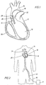
- Fig. 1 is an illustrative view of a section of a human heart depicting the preferred position of the pump of the invention in the left ventricle of the heart;
- Fig. 2 is a schematic view illustrating the insertion of the pump of the invention through the femoral artery of a patient;
- Fig. 3 is a partial sectional view of the pump of the invention;
- Fig. 4 is a partial sectional view of an alternate embodiment of the pump of the invention;
- Fig. 5 is a partial sectional view of a single stage embodiment of the pump of the invention; and
- Fig. 6 is an illustrative view of a section of a human heart depicting an alternate embodiment of the pump of the invention.
- Referring first to Figs. 1 and 2 of the drawings, the blood pump of the invention is shown inserted in the
left ventricle 10 of theheart 12. The blood pump is generally identified by thereference numeral 14 and is carried at the forward end of acatheter 16. Access to theheart 12 is provided in the preferred embodiment through thefemoral artery 18. This is the preferred insertion point, however, it is understood that theheart 12 may be accessed through other arteries or other surgical means. In the preferred embodiment, theblood pump 14 is located in theleft ventricle 10. However, in some circumstances it may be desirable to locate theblood pump 14 in theright ventricle 20. Access to theright ventricle 20 may be provided through thepulmonary artery 22. In operation, the intake end of theblood pump 14 shown in Fig. 1 is located within theleft ventricle 10. The outlet or discharge end of theblood pump 14 is located in theaorta 24. Theblood pump 14 thus extends partially into theleft ventricle 10 through theheart valve 26. Blood is pumped through theblood pump 14 from theleft ventricle 10 in the direction of thearrows 28 into theaorta 24. - In some patients, it may not be desirable to position the
pump 14 within theleft ventricle 10. In those circumstances, thepump 14 is provided with asuction tube 15 mounted to the intake end of thepump 14. Thesuction tube 15 is formed of a flexible, elastomeric material and projects from the intake end of thepump 14 into theleft ventricle 10 of theheart 12 as shown in Fig. 6. - Referring now to Fig. 3, the
pump 14 is shown in greater detail. Thepump 14 is driven by aflexible drive shaft 30 which extends through thecatheter 16. Thedrive shaft 30 is driven by amotor 31 located outside the patient's body, as best shown in Fig. 2. Thepump 14 is secured to the distal end of thecatheter 16. Thepump 14 andcatheter 16 are guided through the femoral artery to theleft ventricle 10. When theleft ventricle 10 is reached, thepump 14 is positioned in theleft ventricle 10 of the heart. Utilizing known insertion techniques, thepump 14 is positioned so that theintake end 32 extends through theheart valve 26 into theleft ventricle 10. Thedischarge end 34 of thepump 14 is positioned outside theleft ventricle 10 so that pumped blood is discharged into theaorta 24 as shown in Fig. 1. - In the embodiment of the invention shown in Fig. 3, the
pump 14 comprises a substantially cylindricalelongate body 36. Theintake end 32 of thebody 36 presents a cone-like profile blunted at its forward end so that it may easily be inserted into theleft ventricle 10 past theheart valve 26 without damaging the heart valve or any of the heart tissue. Theintake end 32 includes a number ofintake ports 38 so that blood collected in theleft ventricle 10 may flow freely into thepump 14. Housed within thehousing 36 is astator 40 and arotor 42. The stator and rotor operate utilizing the moineau pumping principal which uses rotary motion to move a seal continuously through thestator 40 for pumping blood through thepump 14. Thestator 40 is fabricated of resilient material and therotor 42 is fabricated of stainless steel material formed in a helical shape. Therotor 42 is connected to thedrive shaft 30 by a flexible joint 44 which permits the end of therotor 42 to move through a helical path as therotor 42 is driven by thedrive shaft 30. - At the discharge end of the
stator 40, adischarge nozzle 46 is provided for directing the pumped blood to theintake end 50 of aventuri tube 48. It will be observed that the discharge end of thedischarge nozzle 46 extends into theintake end 50 of theventuri tube 48. Anannular space 52 is thus defined between the discharge end 49 of thedischarge nozzle 46 and theintake end 50 of theventuri tube 48. Theintake end 50 of theventuri tube 48 is open to achamber 54 formed within thehousing 36 about thedischarge nozzle 46 andventuri tube 48. Blood collected in theleft ventricle 10 enters thechamber 54 through a plurality ofports 56. - In operation, blood from the
left ventricle 10, in the embodiment of Fig. 3, is sucked through theintake 32 and pumped into thedischarge nozzle 46 by rotation of therotor 42. The blood is pressurized as it is pumped through thedischarge nozzle 46 by restricting the discharge area of thedischarge nozzle 46 and thereby jetting the blood into theventuri tube 48. The restriction in thedischarge nozzle 46 andventuri tube 48 are designed to cause the pumped blood passing through thedischarge nozzle 48 to attain venturi velocities which can be precisely determined. At venturi velocities, negative pressure is produced in theannular space 52 around the discharge end 49 of thedischarge nozzle 46. Thus, blood collected in thechamber 56, which is open to theleft ventricle 10, is sucked into theventuri tube 48 through theintake end 50 and admixed with the blood flow discharged through thedischarge nozzle 46. The outlet end of theventuri tube 48 tapers outwardly, as shown in Fig. 3. The downstream pressure in theventuri tube 48 is thus reduced as the cross-sectional area of theventuri tube 48 increases. The blood pressure at the outlet end of theventuri tube 48 is reduced so that it is equal to intake pressure at theintake end 32 of thepump 14. In this manner, a larger volume of blood may be pumped through thepump 14 at low pressure. For example, thepump 14 at itsintake end 32 may be moving one liter of blood per minute at three psi. However, as this blood volume is passed through thedischarge nozzle 46 into theventuri tube 48 the pressure in theventuri tube 48 increases to nine psi, thereby creating negative pressure in theannular space 52. The negative pressure draws an additional two liters of blood from thechamber 54 into the stream of blood pumped into theventuri tube 48. The pressure drops back to three psi at the discharge end of theventuri tube 48. By passing the pumped blood through theventuri tube 48, three liters of blood per minute is pumped by thepump 14 at three psi. The blood is discharged into theaorta 24 throughoutlet ports 58 formed in the discharge end 34 of thepump 14. - Referring now to Fig. 4, an alternate embodiment of the pump of the invention generally identified by the
reference numeral 60 is shown. Thepump 60 utilizes the same moineau type pumping principal to move blood through the pump, however, the stator and rotor are modified somewhat as will be described in grater detail. Thepump 60 is positioned in theleft ventricle 10 of theheart 12 by thecatheter 16 in the same manner as previously described with regard to pump 14. - The
pump 60 is very similar to thepump 14 and therefore like reference numerals are used to indicate like elements. The stator 62 of thepump 60, however, is provided with multiple suction intake ports which discharge into a common discharge duct. The stator 62 is fabricated of a resilient material and includes threeintake ports intake port 64 is located at the forward end of thestator 64. Theintake ports intake ports separate rotor cavities pump 60. The rotor cavities 70, 72 and 74 includeoutlet ports common discharge duct 82. The rotor cavities 70, 72 and 74 are separated byshaft stabilizers 84 which support and seal about therotor 86 within the rotor cavity of thepump 60. Therotor 86 is driven bydrive shaft 88 which is connected to thedrive motor 31. Thedrive shaft 88 is connected to therotor 86 by a flexible joint 90 which permits the end of therotor 86 to move through a slight orbital path as therotor 86 is rotated by thedrive shaft 88. - The
pump 60 shown in Fig. 4, permits multistage pumping by a single rotor and stator so that a greater volume of blood is pumped through thepump 60 with each revolution of therotor 86. The rotor cavities 70, 72 and 74 are configured for separate and individual pumping upon rotation of therotor 86. In operation, rotation of therotor 86 by thedrive shaft 88 moves a seal continuously through each of thecavities rotor 86 rotates, blood enters therotor cavities intake ports rotor 86 sweeps therotor cavities outlet ports common discharge duct 82 and then into theconduit 92 which discharges into theaorta 24 throughoutlet ports 93. - Referring now to Fig. 5, a single stage embodiment of the heart assist pump of the invention is shown. The
single stage pump 100 is substantially identical to themultistage pump 60 show in Fig. 4. It is placed in theleft ventricle 10 of theheart 12 in substantially the same manner as previously described. Thesingle stage pump 100 comprises astator 102 which houses arotor 104. Thestator 102 is fabricated of resilient material so that a rotating seal is formed with the helical shapedstainless steel rotor 104. Thestator 102 includes ahelical rotor cavity 101 having an intake port 106 and anoutlet port 108. Therotor 104 is connected to adrive shaft 110 by a flexible joint 112. Thedrive shaft 110 is centrally positioned within thedischarge conduit 114 of thepump 100 by ashaft stabilizer 116. - In operation, the
single stage pump 100 draws blood from theleft ventricle 10 through the intake port 106. As therotor 104 rotates, a moving seal is formed with thestator 102 so that blood is pumped through thehelical cavity 102 and discharged into theconduit 114. Theshaft stabilizer 116 includes a plurality ofapertures 118 extending therethrough permitting blood to flow past theshaft stabilizer 116 to be discharged into theaorta 24 throughoutlet ports 120 located in the rear wall of the thepump 100. - The heart assist pump of the present invention utilizes the geometrical relationship between the rotor and the stator to pump blood from the heart of a patient. In cross-section, the rotor and stator are in contact with each other at two points which form two sealing lines over the length of the rotor and stator. The rotor has a single helix shape and is typically fabricated of a metallic material. The stator is formed as a double helix and is typically fabricated of an elastomer. The interference or compression fit between the rotor and stator creates a series of sealed chambers or cavities. Pumping action is achieved by the rotor driven eccentrically within the stator. Fluid, such as blood, enters the cavity formed at the inlet end of the pump and progresses within the cavity and is discharged through the outlet end. Because the force generating sections of the rotor and stator are smooth and curved, very little surface area is available for contact stress. In cross-section, the stator is obround while the rotor in cross-section is circular. The dissimilarity of the shapes between the rotor and stator creates wedge-shaped cavities within the pump unit. Rotation exerts a progressive displacement of the wedge-shaped cavities. In doing so, blood seeks an exit without turbulence. Thus, the volume of blood flowing through the pump of the invention is directly proportional to rotor speed. Blood contained in the sealed cavities which are formed as the rotor turns is displaced axially and with complete continuity from the suction or inlet end to the outlet end of the pump. Despite the fact that the rotor rotates, no turbulence is produced. The constant volume of the enclosed cavities eliminates pressurizing forces and thus a low surge pumping action is accomplished which is ideal for shear sensitive materials.
- The pump of the present disclosure is self-priming and non-cavitating. The prime creates the suction movement of material without which the material cannot be moved. A progressive cavity pump of the type disclosed herein is always in prime. Impeller pumps, however, loose prime and over-accelerate. Over-acceleration can produce cavitation within the pump, resulting in pockets of partial vacuums in the blood flow, causing the separation of blood parts. Blood, being a non-Newtonian fluid, is more susceptible to such spontaneous, non-linear viscoelastic behavior. In viscometric fluid motion, each fluid element is undergoing a steady sheering motion. However, in non-linear viscoelastic responses, the symmetry of a simple flow is replaced by functional stress factors and turbulence with loss of efficiencies. More simply stated, the heart assist pump of the present disclosure maintains a non-turbulent, constant volume of blood in the enclosed cavities with no pressurizing forces. The low surge action of the pump disclosed herein produces an ideal flow with very predictable Newtonian flow regiments.
- The pump of the present invention is dimensioned to provide blood flow of three to four liters per minute, yet it operates at a speed of approximately 2,500 rpm to produce the required blood flow to sustain a patient while the patient's heart is resting and repairing itself. The pump of the present disclosure does not utilize propellers or turbine blades to pump blood. The moineau type pump of the present invention substantially reduces or eliminates the risk of hemolysis. The blood is pumped through the pump of the invention by a rotating seal formed between the stator and helical rotor as described above. The blood is thus pushed through the stator cavity with each rotation of the rotor. No shear forces are developed that would damage the blood cells as the blood is pumped through the pump and discharged into the aorta of the patient.
- While the foregoing is directed to the preferred embodiment of the present invention, other and further embodiments of the invention may be devised without departing from the basic scope thereof, and the scope thereof is determined by the claims which follow.
Claims (10)
- A temporary circulatory assist pump, comprising:(a) an elongate, cylindrical housing (36) having at least one intake port (38) and at least one discharge port (58), said housing (36) being sized for passage through a human blood vessel (18) and insertion into a heart (12)(b) pump means (14), including a stator (40) and a rotor (42), within said housing for assisting the heart of a patient to pump blood;(c) said housing (36) including discharge means (34) for discharging blood into the vascular system of the patient;(d) extravascular power means (31) connected to said pump means (14) for driving said rotor (42); and(e) drive shaft means (30) connecting said pump means (14) to said power means (31);characterised in that said pump means is a moineau type pump means, said rotor (42) having a single helix shape whereby orbiting motion of the rotor (42) moves a rotating seal formed by contact between the stator and the helical rotor continuously through the stator (40) for pumping of blood therethrough; and said drive shaft means (30) is connected to said rotor (42) by a flexible joint (44) enabling said rotor (42) to move through an orbital path upon rotation of said rotor (42) by said power means (31).
- A pump according to claim 1 including a discharge nozzle (46) supported within said housing (36) in line with said stator (40), said discharge nozzle (46) including a restriction for pressurizing and jetting blood pumped therethrough.
- A pump according to claim 2 including a venturi tube (48) located within said housing (36) in line with said discharge nozzle (46), said venturi tube (48) cooperating with said discharge nozzle (46) for forming a negative pressure area within said housing (36).
- A pump according to claim 3 wherein said housing (36) includes a suction chamber (54) formed about a portion of said discharge nozzle (46) and said venturi tube (48), said suction chamber (54) being in fluid communication with said negative pressure area, said suction chamber (54) further including at least one intake port (56) permitting blood to flow into said suction chamber (54).
- A pump according to claim 4 wherein blood collected in said suction chamber (54) is forced through said venturi tube (48) by suction created in the negative pressure area about the discharge end of said discharge nozzle (46).
- A pump according to any preceding claim wherein said pump means (14, 60) includes at least two separate intake ports (64, 66, 68) in fluid communication with separate rotor cavities (70, 72, 74) formed in said pump means (14, 60), and wherein said separate cavities (70, 72, 74) include separate exit ports (76, 78, 80) in fluid communication with a common discharge duct (82).
- A pump according to claim 6 wherein said separate rotor cavities (70, 72, 74) are separated by at least one shaft stabilizer (84) supporting said rotor (86) within said stator (62).
- A pump according to any preceding claim wherein said stator (40) is fabricated of resilient material and said rotor (42) is fabricated of stainless steel and is rotatable within said stator (40).
- A pump according to any preceding claim including a suction tube (15) projecting forwardly from said cylindrical housing (36) for insertion into the heart, said suction tube (15) providing a passage for blood flow to said pump means (14).
- A pump according to any preceding claim wherein said. cylindrical housing (36) carrying said pump means (14) is mounted to the distal end of a catheter (16) and guided to the heart of a patient by said catheter (16).
Priority Applications (2)
| Application Number | Priority Date | Filing Date | Title |
|---|---|---|---|
| DE69027029T DE69027029T2 (en) | 1988-09-27 | 1990-10-09 | Cardiac assist pump |
| AT90311063T ATE137980T1 (en) | 1988-09-27 | 1990-10-09 | CARDIAC SUPPORT PUMP |
Applications Claiming Priority (1)
| Application Number | Priority Date | Filing Date | Title |
|---|---|---|---|
| US07/249,830 US4964864A (en) | 1988-09-27 | 1988-09-27 | Heart assist pump |
Publications (2)
| Publication Number | Publication Date |
|---|---|
| EP0480101A1 EP0480101A1 (en) | 1992-04-15 |
| EP0480101B1 true EP0480101B1 (en) | 1996-05-15 |
Family
ID=22945204
Family Applications (1)
| Application Number | Title | Priority Date | Filing Date |
|---|---|---|---|
| EP90311063A Expired - Lifetime EP0480101B1 (en) | 1988-09-27 | 1990-10-09 | Heart assist pump |
Country Status (5)
| Country | Link |
|---|---|
| US (2) | US4964864A (en) |
| EP (1) | EP0480101B1 (en) |
| AT (1) | ATE137980T1 (en) |
| AU (1) | AU641430B2 (en) |
| DE (1) | DE69027029T2 (en) |
Cited By (8)
| Publication number | Priority date | Publication date | Assignee | Title |
|---|---|---|---|---|
| US5746709A (en) * | 1996-04-25 | 1998-05-05 | Medtronic, Inc. | Intravascular pump and bypass assembly and method for using the same |
| US5814011A (en) * | 1996-04-25 | 1998-09-29 | Medtronic, Inc. | Active intravascular lung |
| US10722631B2 (en) | 2018-02-01 | 2020-07-28 | Shifamed Holdings, Llc | Intravascular blood pumps and methods of use and manufacture |
| US11185677B2 (en) | 2017-06-07 | 2021-11-30 | Shifamed Holdings, Llc | Intravascular fluid movement devices, systems, and methods of use |
| US11511103B2 (en) | 2017-11-13 | 2022-11-29 | Shifamed Holdings, Llc | Intravascular fluid movement devices, systems, and methods of use |
| US11654275B2 (en) | 2019-07-22 | 2023-05-23 | Shifamed Holdings, Llc | Intravascular blood pumps with struts and methods of use and manufacture |
| US11724089B2 (en) | 2019-09-25 | 2023-08-15 | Shifamed Holdings, Llc | Intravascular blood pump systems and methods of use and control thereof |
| US11964145B2 (en) | 2019-07-12 | 2024-04-23 | Shifamed Holdings, Llc | Intravascular blood pumps and methods of manufacture and use |
Families Citing this family (127)
| Publication number | Priority date | Publication date | Assignee | Title |
|---|---|---|---|---|
| US4964864A (en) * | 1988-09-27 | 1990-10-23 | American Biomed, Inc. | Heart assist pump |
| JPH0636821B2 (en) * | 1990-03-08 | 1994-05-18 | 健二 山崎 | Implantable auxiliary artificial heart |
| US5163910A (en) * | 1990-04-10 | 1992-11-17 | Mayo Foundation For Medical Education And Research | Intracatheter perfusion pump apparatus and method |
| US5092844A (en) * | 1990-04-10 | 1992-03-03 | Mayo Foundation For Medical Education And Research | Intracatheter perfusion pump apparatus and method |
| US5300112A (en) * | 1992-07-14 | 1994-04-05 | Aai Corporation | Articulated heart pump |
| US5376114A (en) * | 1992-10-30 | 1994-12-27 | Jarvik; Robert | Cannula pumps for temporary cardiac support and methods of their application and use |
| US5947892A (en) * | 1993-11-10 | 1999-09-07 | Micromed Technology, Inc. | Rotary blood pump |
| EP0764448B1 (en) * | 1995-09-22 | 2003-07-30 | United States Surgical Corporation | Cardiac support device |
| DE19535781C2 (en) * | 1995-09-26 | 1999-11-11 | Fraunhofer Ges Forschung | Device for active flow support of body fluids |
| US5810836A (en) * | 1996-03-04 | 1998-09-22 | Myocardial Stents, Inc. | Device and method for trans myocardial revascularization (TMR) |
| US6015272A (en) * | 1996-06-26 | 2000-01-18 | University Of Pittsburgh | Magnetically suspended miniature fluid pump and method of designing the same |
| US6244835B1 (en) | 1996-06-26 | 2001-06-12 | James F. Antaki | Blood pump having a magnetically suspended rotor |
| US5851174A (en) * | 1996-09-17 | 1998-12-22 | Robert Jarvik | Cardiac support device |
| ES2227718T3 (en) * | 1996-10-04 | 2005-04-01 | United States Surgical Corporation | CIRCULATORY SUPPORT SYSTEM. |
| US6123725A (en) * | 1997-07-11 | 2000-09-26 | A-Med Systems, Inc. | Single port cardiac support apparatus |
| US7182727B2 (en) * | 1997-07-11 | 2007-02-27 | A—Med Systems Inc. | Single port cardiac support apparatus |
| US6532964B2 (en) * | 1997-07-11 | 2003-03-18 | A-Med Systems, Inc. | Pulmonary and circulatory blood flow support devices and methods for heart surgery procedures |
| US6889082B2 (en) | 1997-10-09 | 2005-05-03 | Orqis Medical Corporation | Implantable heart assist system and method of applying same |
| US6007478A (en) * | 1997-11-13 | 1999-12-28 | Impella Cardiotechnik Aktiengesellschaft | Cannula having constant wall thickness with increasing distal flexibility and method of making |
| US6086527A (en) * | 1998-04-02 | 2000-07-11 | Scimed Life Systems, Inc. | System for treating congestive heart failure |
| US7329236B2 (en) | 1999-01-11 | 2008-02-12 | Flowmedica, Inc. | Intra-aortic renal drug delivery catheter |
| US6749598B1 (en) | 1999-01-11 | 2004-06-15 | Flowmedica, Inc. | Apparatus and methods for treating congestive heart disease |
| US7780628B1 (en) | 1999-01-11 | 2010-08-24 | Angiodynamics, Inc. | Apparatus and methods for treating congestive heart disease |
| US7122019B1 (en) | 2000-11-28 | 2006-10-17 | Flowmedica Inc. | Intra-aortic renal drug delivery catheter |
| US7481803B2 (en) | 2000-11-28 | 2009-01-27 | Flowmedica, Inc. | Intra-aortic renal drug delivery catheter |
| US20020128587A1 (en) * | 1999-01-13 | 2002-09-12 | A-Med Systems, Inc. | Pulmonary and circulatory blood flow support devices and methods for heart surgery procedures |
| US6245007B1 (en) | 1999-01-28 | 2001-06-12 | Terumo Cardiovascular Systems Corporation | Blood pump |
| US7022100B1 (en) * | 1999-09-03 | 2006-04-04 | A-Med Systems, Inc. | Guidable intravascular blood pump and related methods |
| US7366754B2 (en) * | 2001-06-29 | 2008-04-29 | Thomson Licensing | Multi-media jitter removal in an asynchronous digital home network |
| CA2374989A1 (en) * | 2002-03-08 | 2003-09-08 | Andre Garon | Ventricular assist device comprising a dual inlet hybrid flow blood pump |
| US7029433B2 (en) * | 2002-03-16 | 2006-04-18 | Chang Sheldon S | Device for cardiac restoration |
| US7241257B1 (en) | 2002-06-28 | 2007-07-10 | Abbott Cardiovascular Systems, Inc. | Devices and methods to perform minimally invasive surgeries |
| US6936222B2 (en) | 2002-09-13 | 2005-08-30 | Kenneth L. Franco | Methods, apparatuses, and applications for compliant membrane blood gas exchangers |
| US7993325B2 (en) | 2002-09-20 | 2011-08-09 | Angio Dynamics, Inc. | Renal infusion systems and methods |
| WO2004032791A2 (en) | 2002-09-20 | 2004-04-22 | Flowmedica, Inc. | Method and apparatus for selective material delivery via an intra-renal catheter |
| US20050197624A1 (en) | 2004-03-04 | 2005-09-08 | Flowmedica, Inc. | Sheath for use in peripheral interventions |
| JP2006513809A (en) | 2002-09-20 | 2006-04-27 | フローメディカ,インコーポレイテッド | Apparatus and method for inserting an intra-aortic catheter through a delivery sheath |
| WO2004030718A2 (en) | 2002-09-20 | 2004-04-15 | Flowmedica, Inc. | Method and apparatus for intra aortic substance delivery to a branch vessel |
| US7063679B2 (en) | 2002-09-20 | 2006-06-20 | Flowmedica, Inc. | Intra-aortic renal delivery catheter |
| US7585836B2 (en) | 2004-05-14 | 2009-09-08 | Goodson Iv Harry Burt | Bi-lateral local renal delivery for treating congestive heart failure and for BNP therapy |
| CA2428741A1 (en) * | 2003-05-13 | 2004-11-13 | Cardianove Inc. | Dual inlet mixed-flow blood pump |
| JP2006526464A (en) | 2003-06-05 | 2006-11-24 | フローメディカ,インコーポレイテッド | System and method for performing bilateral intervention or diagnosis in a branched body lumen |
| US20060167437A1 (en) * | 2003-06-17 | 2006-07-27 | Flowmedica, Inc. | Method and apparatus for intra aortic substance delivery to a branch vessel |
| EP1659970A4 (en) * | 2003-08-05 | 2008-05-21 | Flowmedica Inc | Sytem and method for prevention of radiocontrast induced nephropathy |
| US7494477B2 (en) * | 2003-09-02 | 2009-02-24 | Pulsecath B.V. | Catheter pump, catheter and fittings therefore and methods of using a catheter pump |
| US7416525B2 (en) | 2003-09-18 | 2008-08-26 | Myrakelle, Llc | Rotary blood pump |
| US7393181B2 (en) | 2004-09-17 | 2008-07-01 | The Penn State Research Foundation | Expandable impeller pump |
| US20060069323A1 (en) * | 2004-09-24 | 2006-03-30 | Flowmedica, Inc. | Systems and methods for bi-lateral guidewire cannulation of branched body lumens |
| JP2009511199A (en) * | 2005-10-11 | 2009-03-19 | フロウメディカ, インコーポレイテッド | Vascular sheath with variable lumen configuration |
| JP2009530041A (en) | 2006-03-23 | 2009-08-27 | ザ・ペン・ステート・リサーチ・ファンデーション | Cardiac assist device with expandable impeller pump |
| JP2009532131A (en) | 2006-03-31 | 2009-09-10 | オーキス メディカル コーポレイション | Rotating blood pump |
| US7771401B2 (en) | 2006-06-08 | 2010-08-10 | Angiodynamics, Inc. | Selective renal cannulation and infusion systems and methods |
| US20080221551A1 (en) * | 2007-03-09 | 2008-09-11 | Flowmedica, Inc. | Acute kidney injury treatment systems and methods |
| US8439859B2 (en) | 2007-10-08 | 2013-05-14 | Ais Gmbh Aachen Innovative Solutions | Catheter device |
| US20090105799A1 (en) * | 2007-10-23 | 2009-04-23 | Flowmedica, Inc. | Renal assessment systems and methods |
| JP5171953B2 (en) | 2008-06-23 | 2013-03-27 | テルモ株式会社 | Blood pump device |
| AU2009302471B2 (en) | 2008-10-06 | 2015-03-19 | Indiana University Research And Technology Corporation | Methods and apparatus for active or passive assistance in the circulatory system |
| EP2372160B1 (en) | 2008-12-08 | 2014-07-30 | Thoratec Corporation | Centrifugal pump device |
| JP5378010B2 (en) | 2009-03-05 | 2013-12-25 | ソラテック コーポレーション | Centrifugal pump device |
| CN102341600B (en) | 2009-03-06 | 2014-12-10 | 胸腔科技有限公司 | Centrifugal pump device |
| EP2246078A1 (en) * | 2009-04-29 | 2010-11-03 | ECP Entwicklungsgesellschaft mbH | Shaft assembly with a shaft which moves within a fluid-filled casing |
| CA2769631A1 (en) | 2009-07-01 | 2011-01-06 | The Penn State Research Foundation | Blood pump with expandable cannula |
| EP2461465B1 (en) | 2009-07-29 | 2018-12-19 | Thoratec Corporation | Rotation drive device and centrifugal pump device |
| US8690749B1 (en) | 2009-11-02 | 2014-04-08 | Anthony Nunez | Wireless compressible heart pump |
| JP5443197B2 (en) | 2010-02-16 | 2014-03-19 | ソラテック コーポレーション | Centrifugal pump device |
| JP5572832B2 (en) | 2010-03-26 | 2014-08-20 | ソーラテック コーポレイション | Centrifugal blood pump device |
| EP2388029A1 (en) * | 2010-05-17 | 2011-11-23 | ECP Entwicklungsgesellschaft mbH | Pump array |
| JP5681403B2 (en) | 2010-07-12 | 2015-03-11 | ソーラテック コーポレイション | Centrifugal pump device |
| JP5577506B2 (en) | 2010-09-14 | 2014-08-27 | ソーラテック コーポレイション | Centrifugal pump device |
| US8485961B2 (en) | 2011-01-05 | 2013-07-16 | Thoratec Corporation | Impeller housing for percutaneous heart pump |
| US8597170B2 (en) | 2011-01-05 | 2013-12-03 | Thoratec Corporation | Catheter pump |
| WO2012094641A2 (en) | 2011-01-06 | 2012-07-12 | Thoratec Corporation | Percutaneous heart pump |
| WO2012094535A2 (en) | 2011-01-06 | 2012-07-12 | Thoratec Corporation | Percutaneous heart pump |
| EP2693609B1 (en) | 2011-03-28 | 2017-05-03 | Thoratec Corporation | Rotation and drive device and centrifugal pump device using same |
| CA2835212A1 (en) | 2011-05-13 | 2012-11-22 | Heartware, Inc. | Intravascular blood pump and method of implantation |
| JP6083929B2 (en) | 2012-01-18 | 2017-02-22 | ソーラテック コーポレイション | Centrifugal pump device |
| US10631863B2 (en) * | 2012-02-01 | 2020-04-28 | St. Jude Medical, Cardiology Division, Inc. | Apparatus for heart valve repair |
| US9872947B2 (en) | 2012-05-14 | 2018-01-23 | Tc1 Llc | Sheath system for catheter pump |
| GB2504176A (en) | 2012-05-14 | 2014-01-22 | Thoratec Corp | Collapsible impeller for catheter pump |
| US9446179B2 (en) | 2012-05-14 | 2016-09-20 | Thoratec Corporation | Distal bearing support |
| US9327067B2 (en) | 2012-05-14 | 2016-05-03 | Thoratec Corporation | Impeller for catheter pump |
| US8721517B2 (en) | 2012-05-14 | 2014-05-13 | Thoratec Corporation | Impeller for catheter pump |
| US9358329B2 (en) | 2012-07-03 | 2016-06-07 | Thoratec Corporation | Catheter pump |
| EP4186557A1 (en) | 2012-07-03 | 2023-05-31 | Tc1 Llc | Motor assembly for catheter pump |
| US9421311B2 (en) | 2012-07-03 | 2016-08-23 | Thoratec Corporation | Motor assembly for catheter pump |
| US9371826B2 (en) | 2013-01-24 | 2016-06-21 | Thoratec Corporation | Impeller position compensation using field oriented control |
| US9556873B2 (en) | 2013-02-27 | 2017-01-31 | Tc1 Llc | Startup sequence for centrifugal pump with levitated impeller |
| US11033728B2 (en) | 2013-03-13 | 2021-06-15 | Tc1 Llc | Fluid handling system |
| EP2968718B1 (en) | 2013-03-13 | 2021-04-21 | Tc1 Llc | Fluid handling system |
| US11077294B2 (en) | 2013-03-13 | 2021-08-03 | Tc1 Llc | Sheath assembly for catheter pump |
| US9308302B2 (en) | 2013-03-15 | 2016-04-12 | Thoratec Corporation | Catheter pump assembly including a stator |
| WO2014143593A1 (en) | 2013-03-15 | 2014-09-18 | Thoratec Corporation | Catheter pump assembly including a stator |
| US10052420B2 (en) | 2013-04-30 | 2018-08-21 | Tc1 Llc | Heart beat identification and pump speed synchronization |
| US9713663B2 (en) | 2013-04-30 | 2017-07-25 | Tc1 Llc | Cardiac pump with speed adapted for ventricle unloading |
| WO2015160979A1 (en) | 2014-04-15 | 2015-10-22 | Thoratec Corporation | Catheter pump with access ports |
| WO2015160990A1 (en) | 2014-04-15 | 2015-10-22 | Thoratec Corporation | Catheter pump introducer systems and methods |
| WO2015160942A1 (en) | 2014-04-15 | 2015-10-22 | Thoratec Corporation | Catheter pump with off-set motor position |
| WO2015160943A1 (en) | 2014-04-15 | 2015-10-22 | Thoratec Corporation | Sensors for catheter pumps |
| DE102014211216A1 (en) * | 2014-06-12 | 2015-12-17 | Universität Duisburg-Essen | Pump for implantation in a vessel |
| US10449279B2 (en) | 2014-08-18 | 2019-10-22 | Tc1 Llc | Guide features for percutaneous catheter pump |
| US9623161B2 (en) | 2014-08-26 | 2017-04-18 | Tc1 Llc | Blood pump and method of suction detection |
| WO2016118784A1 (en) | 2015-01-22 | 2016-07-28 | Thoratec Corporation | Attachment mechanisms for motor of catheter pump |
| WO2016118777A1 (en) | 2015-01-22 | 2016-07-28 | Thoratec Corporation | Reduced rotational mass motor assembly for catheter pump |
| EP3598986B1 (en) | 2015-01-22 | 2021-02-17 | Tc1 Llc | Motor assembly with heat exchanger for catheter pump |
| EP3256183A4 (en) | 2015-02-11 | 2018-09-19 | Tc1 Llc | Heart beat identification and pump speed synchronization |
| US10166318B2 (en) | 2015-02-12 | 2019-01-01 | Tc1 Llc | System and method for controlling the position of a levitated rotor |
| US10371152B2 (en) | 2015-02-12 | 2019-08-06 | Tc1 Llc | Alternating pump gaps |
| US10245361B2 (en) | 2015-02-13 | 2019-04-02 | Tc1 Llc | Impeller suspension mechanism for heart pump |
| US9907890B2 (en) | 2015-04-16 | 2018-03-06 | Tc1 Llc | Catheter pump with positioning brace |
| US10117983B2 (en) | 2015-11-16 | 2018-11-06 | Tc1 Llc | Pressure/flow characteristic modification of a centrifugal pump in a ventricular assist device |
| US11160970B2 (en) | 2016-07-21 | 2021-11-02 | Tc1 Llc | Fluid seals for catheter pump motor assembly |
| EP3808401A1 (en) | 2016-07-21 | 2021-04-21 | Tc1 Llc | Gas-filled chamber for catheter pump motor assembly |
| JP7383476B2 (en) | 2016-10-25 | 2023-11-20 | マジェンタ・メディカル・リミテッド | ventricular assist device |
| US10905808B2 (en) | 2018-01-10 | 2021-02-02 | Magenta Medical Ltd. | Drive cable for use with a blood pump |
| EP4039321A1 (en) | 2018-01-10 | 2022-08-10 | Magenta Medical Ltd. | Ventricular assist device |
| DE102018201030A1 (en) | 2018-01-24 | 2019-07-25 | Kardion Gmbh | Magnetic coupling element with magnetic bearing function |
| US11690997B2 (en) | 2018-04-06 | 2023-07-04 | Puzzle Medical Devices Inc. | Mammalian body conduit intralumenal device and lumen wall anchor assembly, components thereof and methods of implantation and explanation thereof |
| US11110264B2 (en) | 2018-04-20 | 2021-09-07 | Cardiovascular Systems, Inc. | Intravascular pump with expandable distal region |
| US11020582B2 (en) | 2018-04-20 | 2021-06-01 | Cardiovascular Systems, Inc. | Intravascular pump with expandable region |
| US11167121B2 (en) | 2018-05-15 | 2021-11-09 | Cardiovascular Systems, Inc. | Intravascular pump with integrated isolated conductor(s) and methods thereof |
| DE102018211327A1 (en) | 2018-07-10 | 2020-01-16 | Kardion Gmbh | Impeller for an implantable vascular support system |
| US11013904B2 (en) | 2018-07-30 | 2021-05-25 | Cardiovascular Systems, Inc. | Intravascular pump with proximal and distal pressure or flow sensors and distal sensor tracking |
| US11202900B2 (en) | 2018-07-31 | 2021-12-21 | Cardiovascular Systems, Inc. | Intravascular pump with controls and display screen on handle |
| WO2020152611A2 (en) | 2019-01-24 | 2020-07-30 | Magenta Medical Ltd | Ventricular assist device |
| DE102020102474A1 (en) | 2020-01-31 | 2021-08-05 | Kardion Gmbh | Pump for conveying a fluid and method for manufacturing a pump |
| US20220226632A1 (en) * | 2020-04-07 | 2022-07-21 | Magenta Medical Ltd | Ventricular assist device |
| WO2023168336A2 (en) * | 2022-03-02 | 2023-09-07 | Xtract Medical, Inc. | Devices and methods for removing material from a patient |
Family Cites Families (17)
| Publication number | Priority date | Publication date | Assignee | Title |
|---|---|---|---|---|
| GB628203A (en) * | 1947-09-04 | 1949-08-24 | Fmc Corp | Improvements in meshing-screw pumps |
| US3479960A (en) * | 1966-12-26 | 1969-11-25 | Magnesita Sa | Encased electric pump |
| US3505987A (en) * | 1967-03-17 | 1970-04-14 | Medrad Inc | Intra-aortic heart pump |
| US3667069A (en) * | 1970-03-27 | 1972-06-06 | Univ Minnesota | Jet pump cardiac replacement and assist device and method of at least partially replacing a disabled right heart |
| DE2453296A1 (en) * | 1974-11-11 | 1976-05-13 | Dieter Von Zeppelin | Pump for medical appln.eg. blood transfusion, - comprises elastic-walled enclosed space conveying element with support and motor-driven pump element |
| US4051840A (en) * | 1976-01-05 | 1977-10-04 | Sinai Hospital Of Detroit | Dynamic aortic patch |
| US4102610A (en) * | 1976-09-03 | 1978-07-25 | John Taboada | Constant volume seal-free reciprocating pump |
| US4173796A (en) * | 1977-12-09 | 1979-11-13 | University Of Utah | Total artificial hearts and cardiac assist devices powered and controlled by reversible electrohydraulic energy converters |
| US4382199A (en) * | 1980-11-06 | 1983-05-03 | Nu-Tech Industries, Inc. | Hydrodynamic bearing system for a brushless DC motor |
| US4625712A (en) * | 1983-09-28 | 1986-12-02 | Nimbus, Inc. | High-capacity intravascular blood pump utilizing percutaneous access |
| US4676725A (en) * | 1985-12-27 | 1987-06-30 | Hughes Tool Company | Moineau type gear mechanism with resilient sleeve |
| US4817586A (en) * | 1987-11-24 | 1989-04-04 | Nimbus Medical, Inc. | Percutaneous bloom pump with mixed-flow output |
| US4846152A (en) * | 1987-11-24 | 1989-07-11 | Nimbus Medical, Inc. | Single-stage axial flow blood pump |
| US4964864A (en) * | 1988-09-27 | 1990-10-23 | American Biomed, Inc. | Heart assist pump |
| US4957504A (en) * | 1988-12-02 | 1990-09-18 | Chardack William M | Implantable blood pump |
| US4969865A (en) * | 1989-01-09 | 1990-11-13 | American Biomed, Inc. | Helifoil pump |
| US4944722A (en) * | 1989-02-23 | 1990-07-31 | Nimbus Medical, Inc. | Percutaneous axial flow blood pump |
-
1988
- 1988-09-27 US US07/249,830 patent/US4964864A/en not_active Expired - Fee Related
-
1990
- 1990-10-02 AU AU63699/90A patent/AU641430B2/en not_active Ceased
- 1990-10-09 DE DE69027029T patent/DE69027029T2/en not_active Expired - Fee Related
- 1990-10-09 EP EP90311063A patent/EP0480101B1/en not_active Expired - Lifetime
- 1990-10-09 AT AT90311063T patent/ATE137980T1/en not_active IP Right Cessation
- 1990-10-22 US US07/601,881 patent/US5112349A/en not_active Expired - Fee Related
Cited By (10)
| Publication number | Priority date | Publication date | Assignee | Title |
|---|---|---|---|---|
| US5746709A (en) * | 1996-04-25 | 1998-05-05 | Medtronic, Inc. | Intravascular pump and bypass assembly and method for using the same |
| US5814011A (en) * | 1996-04-25 | 1998-09-29 | Medtronic, Inc. | Active intravascular lung |
| US11185677B2 (en) | 2017-06-07 | 2021-11-30 | Shifamed Holdings, Llc | Intravascular fluid movement devices, systems, and methods of use |
| US11717670B2 (en) | 2017-06-07 | 2023-08-08 | Shifamed Holdings, LLP | Intravascular fluid movement devices, systems, and methods of use |
| US11511103B2 (en) | 2017-11-13 | 2022-11-29 | Shifamed Holdings, Llc | Intravascular fluid movement devices, systems, and methods of use |
| US10722631B2 (en) | 2018-02-01 | 2020-07-28 | Shifamed Holdings, Llc | Intravascular blood pumps and methods of use and manufacture |
| US11229784B2 (en) | 2018-02-01 | 2022-01-25 | Shifamed Holdings, Llc | Intravascular blood pumps and methods of use and manufacture |
| US11964145B2 (en) | 2019-07-12 | 2024-04-23 | Shifamed Holdings, Llc | Intravascular blood pumps and methods of manufacture and use |
| US11654275B2 (en) | 2019-07-22 | 2023-05-23 | Shifamed Holdings, Llc | Intravascular blood pumps with struts and methods of use and manufacture |
| US11724089B2 (en) | 2019-09-25 | 2023-08-15 | Shifamed Holdings, Llc | Intravascular blood pump systems and methods of use and control thereof |
Also Published As
| Publication number | Publication date |
|---|---|
| DE69027029D1 (en) | 1996-06-20 |
| DE69027029T2 (en) | 1997-01-23 |
| AU6369990A (en) | 1992-06-11 |
| AU641430B2 (en) | 1993-09-23 |
| US5112349A (en) | 1992-05-12 |
| EP0480101A1 (en) | 1992-04-15 |
| US4964864A (en) | 1990-10-23 |
| ATE137980T1 (en) | 1996-06-15 |
Similar Documents
| Publication | Publication Date | Title |
|---|---|---|
| EP0480101B1 (en) | Heart assist pump | |
| US5112292A (en) | Helifoil pump | |
| US4969865A (en) | Helifoil pump | |
| US10874783B2 (en) | Catheter device | |
| US20220134082A1 (en) | Catheter device | |
| CA3020247C (en) | Catheter device | |
| CA2927346C (en) | Catheter device | |
| US5222980A (en) | Implantable heart-assist device | |
| JPH11511370A (en) | System for actively supporting body fluid flow | |
| JPH04176471A (en) | Circulation auxiliary pump | |
| CA2026692A1 (en) | Heart assist pump | |
| CA2026693A1 (en) | Helifoil pump | |
| JPH04156856A (en) | Pump for circulatory assistance |
Legal Events
| Date | Code | Title | Description |
|---|---|---|---|
| PUAI | Public reference made under article 153(3) epc to a published international application that has entered the european phase |
Free format text: ORIGINAL CODE: 0009012 |
|
| AK | Designated contracting states |
Kind code of ref document: A1 Designated state(s): AT BE CH DE DK ES FR GB GR IT LI LU NL SE |
|
| 17P | Request for examination filed |
Effective date: 19921007 |
|
| 17Q | First examination report despatched |
Effective date: 19940509 |
|
| GRAH | Despatch of communication of intention to grant a patent |
Free format text: ORIGINAL CODE: EPIDOS IGRA |
|
| GRAA | (expected) grant |
Free format text: ORIGINAL CODE: 0009210 |
|
| AK | Designated contracting states |
Kind code of ref document: B1 Designated state(s): AT BE CH DE DK ES FR GB GR IT LI LU NL SE |
|
| PG25 | Lapsed in a contracting state [announced via postgrant information from national office to epo] |
Ref country code: NL Free format text: LAPSE BECAUSE OF FAILURE TO SUBMIT A TRANSLATION OF THE DESCRIPTION OR TO PAY THE FEE WITHIN THE PRESCRIBED TIME-LIMIT Effective date: 19960515 Ref country code: LI Effective date: 19960515 Ref country code: GR Free format text: LAPSE BECAUSE OF FAILURE TO SUBMIT A TRANSLATION OF THE DESCRIPTION OR TO PAY THE FEE WITHIN THE PRESCRIBED TIME-LIMIT Effective date: 19960515 Ref country code: ES Free format text: THE PATENT HAS BEEN ANNULLED BY A DECISION OF A NATIONAL AUTHORITY Effective date: 19960515 Ref country code: DK Effective date: 19960515 Ref country code: CH Effective date: 19960515 Ref country code: BE Effective date: 19960515 Ref country code: AT Effective date: 19960515 |
|
| REF | Corresponds to: |
Ref document number: 137980 Country of ref document: AT Date of ref document: 19960615 Kind code of ref document: T |
|
| REF | Corresponds to: |
Ref document number: 69027029 Country of ref document: DE Date of ref document: 19960620 |
|
| ITF | It: translation for a ep patent filed |
Owner name: STUDIO ING. ALFREDO RAIMONDI |
|
| PG25 | Lapsed in a contracting state [announced via postgrant information from national office to epo] |
Ref country code: SE Effective date: 19960815 |
|
| ET | Fr: translation filed | ||
| PG25 | Lapsed in a contracting state [announced via postgrant information from national office to epo] |
Ref country code: LU Free format text: LAPSE BECAUSE OF NON-PAYMENT OF DUE FEES Effective date: 19961031 |
|
| NLV1 | Nl: lapsed or annulled due to failure to fulfill the requirements of art. 29p and 29m of the patents act | ||
| REG | Reference to a national code |
Ref country code: CH Ref legal event code: PL |
|
| PLBE | No opposition filed within time limit |
Free format text: ORIGINAL CODE: 0009261 |
|
| STAA | Information on the status of an ep patent application or granted ep patent |
Free format text: STATUS: NO OPPOSITION FILED WITHIN TIME LIMIT |
|
| 26N | No opposition filed | ||
| PGFP | Annual fee paid to national office [announced via postgrant information from national office to epo] |
Ref country code: GB Payment date: 19970930 Year of fee payment: 8 |
|
| PGFP | Annual fee paid to national office [announced via postgrant information from national office to epo] |
Ref country code: DE Payment date: 19971017 Year of fee payment: 8 |
|
| PG25 | Lapsed in a contracting state [announced via postgrant information from national office to epo] |
Ref country code: GB Free format text: LAPSE BECAUSE OF NON-PAYMENT OF DUE FEES Effective date: 19981009 |
|
| PGFP | Annual fee paid to national office [announced via postgrant information from national office to epo] |
Ref country code: FR Payment date: 19990430 Year of fee payment: 9 |
|
| GBPC | Gb: european patent ceased through non-payment of renewal fee |
Effective date: 19981009 |
|
| PG25 | Lapsed in a contracting state [announced via postgrant information from national office to epo] |
Ref country code: DE Free format text: LAPSE BECAUSE OF NON-PAYMENT OF DUE FEES Effective date: 19990803 |
|
| PG25 | Lapsed in a contracting state [announced via postgrant information from national office to epo] |
Ref country code: FR Free format text: LAPSE BECAUSE OF NON-PAYMENT OF DUE FEES Effective date: 20000630 |
|
| REG | Reference to a national code |
Ref country code: FR Ref legal event code: ST |
|
| PG25 | Lapsed in a contracting state [announced via postgrant information from national office to epo] |
Ref country code: IT Free format text: LAPSE BECAUSE OF NON-PAYMENT OF DUE FEES;WARNING: LAPSES OF ITALIAN PATENTS WITH EFFECTIVE DATE BEFORE 2007 MAY HAVE OCCURRED AT ANY TIME BEFORE 2007. THE CORRECT EFFECTIVE DATE MAY BE DIFFERENT FROM THE ONE RECORDED. Effective date: 20051009 |