EP0479768A2 - Method for administration of radio channels - Google Patents
Method for administration of radio channels Download PDFInfo
- Publication number
- EP0479768A2 EP0479768A2 EP91890233A EP91890233A EP0479768A2 EP 0479768 A2 EP0479768 A2 EP 0479768A2 EP 91890233 A EP91890233 A EP 91890233A EP 91890233 A EP91890233 A EP 91890233A EP 0479768 A2 EP0479768 A2 EP 0479768A2
- Authority
- EP
- European Patent Office
- Prior art keywords
- data
- radio channels
- transmission path
- transmission
- center
- Prior art date
- Legal status (The legal status is an assumption and is not a legal conclusion. Google has not performed a legal analysis and makes no representation as to the accuracy of the status listed.)
- Granted
Links
Images


Classifications
-
- H—ELECTRICITY
- H04—ELECTRIC COMMUNICATION TECHNIQUE
- H04J—MULTIPLEX COMMUNICATION
- H04J3/00—Time-division multiplex systems
- H04J3/02—Details
- H04J3/12—Arrangements providing for calling or supervisory signals
- H04J3/125—One of the channel pulses or the synchronisation pulse is also used for transmitting monitoring or supervisory signals
-
- H—ELECTRICITY
- H04—ELECTRIC COMMUNICATION TECHNIQUE
- H04W—WIRELESS COMMUNICATION NETWORKS
- H04W88/00—Devices specially adapted for wireless communication networks, e.g. terminals, base stations or access point devices
- H04W88/08—Access point devices
Definitions
- the invention relates to a method for the management of radio channels, in which the data of a center are transmitted via at least one sub-center and from this via transmitting or receiving units and the radio channels to mobile stations or vice versa, and the voice data and the signaling data for the transmission - and receiving units of the individual radio channels are managed by a line management system.
- radio-based communication such as is used in air traffic control systems
- several radio channels are managed by a control center and the necessary transmitters and receivers are controlled.
- the communication channels between the head office and the transmitting and receiving stations are formed by telephone lines, coax lines or radio links.
- a transmission path for voice and alternating current telegraph channels for telecontrol signals for controlling the transmitter and receiver are required for each radio channel. Since the reliability of such transmission lines is not particularly great, especially when using directional radio links, and on the other hand the reliability of the overall system is an important system feature, additional reserve line routes must be provided, which can replace a failed regular transmission route at short notice. Due to the reserve and the large number of transmission paths that are always available, the operating costs for such a communication system are very high.
- the aim of the invention is therefore to reduce the effort for the fail-safe connection of the control center to a sub-control center.
- FIG. 1 shows a typical structure of a communication system with radio channels.
- a center 1 receives messages to be transmitted in M radio channels via directly connected workplaces, switching systems, telephone connections or further radio links, with additional signaling information (squelch, PTT, AGC, etc.) also having to be transmitted in addition to the voice data.
- the voice data and signaling data of each radio channel are to generally mobile stations 15, such as communication partners, such as Airplanes.
- each radio channel is continuously transmitted to the receiver via its own transmission path, but rather that several, namely N radio channels are transmitted between the center and a sub-control center to the sub-control center 2 using the time division multiplex method, pulse code modulated.
- N is contained in M and, if appropriate, a sub-center for the "divisional remainder".
- the output data of the sub-center 2 are transmitted to a transmitting station 3, the transmission to the mobile stations 15 taking place via radio-based communication.
- Each transmission path 7 from the center to a sub-center has a transmission capacity X.
- the transmission capacity is 64 kbit / sec.
- the local connection from the sub-center to the transmitter 3 is generally through an analog transmission path in the baseband, e.g. a telephone line.
- a telecontrol center 5 can also be connected to the control center 1, the telecontrol information also being transmitted via the transmission paths 7 to the respective sub-control centers 2, to each of them a telecontrol subcentral 6 is connected, in which the telecontrol commands are evaluated.
- both the control center 1 and each sub-control center 2 each have a line management unit 8, 9.
- the invention is not limited to such a transmission path.
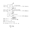
- FIG. 2a shows line management units 8, 8 ', 8 "of the center, this arrangement differing from that on the part of the sub-centers only in that inputs of line management units 8 correspond to the central outputs of line management units 9 of sub-center 2 and outputs of the central inputs
- the lines since duplex operation is required for each connection in general, according to the state of the art, the lines must either be operated bidirectionally or physically consist of two parallel line strings, each with simplex operation. This is not essential for the function of the line management system according to the invention and will therefore not explained further.
- the center comprises, for example, three line management units 8, 8 ', 8 ", each of which operates a line LTG1, LTG2, LTG3. These lines correspond to the transmission paths 7 in FIG. 1 and each have a total transmission capacity of 64 kbit / sec .
- the signals of the radio channels f1 to f3 are present at the inputs of the line management unit 8, and signals of the radio channels f4 to f6 are present at the inputs of the line management unit 8 '.
- the line management unit 8 is used in the described embodiment as a reserve unit for equivalent circuits.
- the three line management units are furthermore connected to one another via an internal PCM cascading highway (14), to which a CODEC unit 13 is also connected.
- the data (signaling, control data such as squelch, push-to-talk, AGC) for the three radio channels f1 to f3 and further telecontrol information are transmitted in a multiplex data channel D1.
- 4 channels namely three radio channels f1, f2, f3 and one data channel D1, each with a data rate of 16 kbit / sec, are transmitted on the line LTG1 using pulse code modulation in time division multiplex.
- the radio channels f4 to f6 are connected to the line management unit 8 'and, together with the data channel D2 assigned to them, are transmitted in time-division multiplex via the line LTG2 in pulse code modulation.
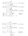
- FIG. 2b schematically shows how, in a further embodiment of the invention, the failure of a line, the failure of the line LTG1 is shown by substituting lines.
- the time-division multiplex signal originally provided for the line LTG1, consisting of the radio channels f1 to f3 and the data channel D1 is controlled by the CODEC unit 13 via transfer the internal cascading highway 14 to the line management unit 8 ′′, which transmits it via the replacement line LTG3.
- the three radio channels f4, f5, f6 and data channel D2 are transmitted as before via line LTG2, the additional services originally transmitted on line LTG3, such as the service telephone, are reset.
- 3 shows the situation in line management units when different priorities can be assigned to the individual radio channels.
- 3a shows a system for transmitting 6 radio channels via two line management units 8, 8 'in an analogous manner to that described in FIG. 2a. In this case too, more than two lines and line management units could be provided without restrictions.
- the radio channels f1 to f3 and the assigned data channel D1 are transmitted via the line LTG1, the radio channels f4 to f6 and the data channel D2 via the line LTG2.
- the radio channels f1 and f4 represent very important channels, that is to say that they also have to be transmitted in the event of a line break, the other radio channels f2, f3 and f5, f6 should be less important, ie, they may fail in the event of a line fault.
- 3b shows schematically how the failure of the line LTG2 is compensated for using a modified method according to the invention, namely the equivalent switching of channels. The less important radio channels of the undisturbed line are switched off and the important channels are transmitted in the slots of the transmission capacity that are freed up as a result.
- the line management unit 8 clears the third capacity slot of its line LTG1 and transmits the important radio channel f4 instead of the originally intended, less important radio channel f3, whereby - controlled by the CODEC unit - its data from the line management unit 8 'via the cascading highway 14 to the Line management unit 8 are supplied.
- the data channel D1 is modified such that the data of the radio channel f4 is transmitted instead of the data for the radio channel f3 that is no longer required.
- all the important radio channels (f1 and f4) with their associated data (in D1 and D2) and additionally one of the less important channels (f2) are transmitted; this means that the remaining transmission capacity is optimally used.
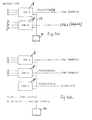
- FIGS. 4 a and 4 b This is to be shown using an example in FIGS. 4 a and 4 b.
- the normal operation of the system corresponds to that of Fig. 2a.
- Three line management units 8, 8 ', 8 "operate three lines LTG1 to LTG3, the first two line management units being assigned three radio channels f1 to f3 and f4 to f6, respectively.
- the third line management unit manages the replacement line LTG3 and transmits additional services via it in normal operation, such as service telephone etc.
- the radio channels f1 and f4 should again represent very important channels, the other channels (f2, f3, f5, f6) should be less important.
- 4 a shows the behavior of the system in the event of a failure of a first line, a failure of the line LTG1 being assumed. Since the system still has a reserve line (LTG3) available, the method of line replacement switching is selected and the radio channels (f1 to f3) and data (D1) provided for the line LTG1 are controlled by the CODEC unit 13 via the cascading highway 14 the line management unit 8 "and further transmitted via the spare line LTG3. If another line, for example LTG2, fails if the line LTG1 has failed, then the method of the channel equivalent circuit is selected, since no further reserve line is available.
- LTG3 reserve line
- the one via the spare line The less important radio channel f3 which is also transmitted with LTG3 is disconnected and the important radio channel f4 originally intended for the now disturbed line LTG2 is transmitted in its place, and its data is also transmitted in the modified data channel D12. In this way, even the failure of several lines can be avoided can be mastered without failure of an important radio channel.
- the invention is not limited to this; In this way, design variants are also conceivable in which only a part of the transmission paths or only a single one of these transmission paths is operated in the manner according to the invention.
Abstract
Description
Die Erfindung betrifft ein Verfahren zur Verwaltung von Funkkanälen, bei welchen die Daten einer Zentrale über zumindestens eine Unterzentrale und von dieser über Sende- bzw. Empfangseinheiten und die Funkkanäle an mobile Stationen bzw. umgekehrt übermittelt werden, und die Sprachdaten und die Signalisierungsdaten für die Sende- und Empfangseinheiten der einzelnen Funkkanäle durch ein Leitungsverwaltungssystem verwaltet werden.The invention relates to a method for the management of radio channels, in which the data of a center are transmitted via at least one sub-center and from this via transmitting or receiving units and the radio channels to mobile stations or vice versa, and the voice data and the signaling data for the transmission - and receiving units of the individual radio channels are managed by a line management system.
Für die funkgestützte Kommunikation, wie sie etwa bei Flugsicherungsanlagen verwendet wird, werden von einer Zentrale mehrere Funkkanäle verwaltet und die dafür notwendigen Sende- und Empfangsanlagen angesteuert. Die Kommunikationswege zwischen der Zentrale und den Sende- und Empfangsstationen werden durch Telefonleitungen, Koax-Leitungen oder Richtfunkstrecken gebildet. Dabei sind entsprechend dem Stand der Technik pro Funkkanal ein Übertragungsweg für Sprache und Wechselstromtelegrafiekanäle für Fernwirksignale zur Steuerung der Sender und Empfänger erforderlich. Da die Zuverlässigkeit solcher Übertragungsleitungen insbesondere bei der Verwendung von Richtfunkstrecken nicht besonders groß ist, andererseits die Zuverlässigkeit des Gesamtsystems ein wichtiges Systemmerkmal darstellt, müssen zusätzliche Reserveleitungswege vorgesehen werden, welche einen ausgefallenen regulären Übertragungsweg kurzfristig ersetzen können. Durch die Reservehaltung und die Vielzahl von ständig verfügbar zu haltenden Übertragungswegen sind die Betriebskosten für ein solches Kommunikationssystem sehr hoch.For radio-based communication, such as is used in air traffic control systems, several radio channels are managed by a control center and the necessary transmitters and receivers are controlled. The communication channels between the head office and the transmitting and receiving stations are formed by telephone lines, coax lines or radio links. According to the state of the art, a transmission path for voice and alternating current telegraph channels for telecontrol signals for controlling the transmitter and receiver are required for each radio channel. Since the reliability of such transmission lines is not particularly great, especially when using directional radio links, and on the other hand the reliability of the overall system is an important system feature, additional reserve line routes must be provided, which can replace a failed regular transmission route at short notice. Due to the reserve and the large number of transmission paths that are always available, the operating costs for such a communication system are very high.
Eine Verbesserung ergibt sich durch den Einsatz von Unterzentralen, von denen die Sende- und Empfangsstationen dezentral angesteuert werden. Dabei sind wohl für jede Empfangs- und Sendestation lokale Verbindungswege zur Unterstation erforderlich aber nur relativ kleine Entfernungen zu überbrücken. Die Unterzentrale ist wiederum über eine Mehrzahl von parallelen Übertragungswegen mit der Zentrale verbunden. Dadurch werden die Gesamtkosten reduziert, da weit weniger Reservekanäle gebraucht werden. Trotzdem müssen immer noch eine Vielzahl von parallelen Übertragungswegen von der Zentrale zur Unterzentrale ständig verfügbar sein.An improvement results from the use of sub-centers, from which the sending and receiving stations are controlled decentrally. Local connection paths to the substation are probably required for each receiving and transmitting station, but only bridging relatively small distances. The sub-center is in turn connected to the center via a plurality of parallel transmission paths. This reduces the overall costs, since far fewer reserve channels are needed. Nevertheless, a large number of parallel transmission paths from the central to the sub-central still have to be available.
Ziel der Erfindung ist es daher, den Aufwand für die ausfallsichere Verbindung der Zentrale zu einer Unterzentrale zu verringern.The aim of the invention is therefore to reduce the effort for the fail-safe connection of the control center to a sub-control center.
Erfindungsgemäß wird dies bei einem Verfahren der eingangs genannten Art dadurch erreicht, daß bei einer gesamten Übertragungskapazität X des Übertragungsweges von der Zentrale zu einer Unterzentrale den Sprachsignalen jedes einzelnen der über diesen Übertragungsweg zu übertragenden N Funkkanäle jeweils eine Teilübertragungskapazität TX < X und den Signalisierungsdaten sowie gegebenenfalls Fernwirkdaten jedes Funkkanals eine Restübertragungskapazität RX = X - N.TX fest zugeordnet wird, und daß die Sprachdaten der Funkkanäle und deren zugehörige Signalierungsdaten sowie gegebenenfalls Fernwirkdaten komprimiert und im Zeitmultiplexverfahren pulscodemoduliert übertragen werden.According to the invention, this is achieved in a method of the type mentioned at the outset in that for a total transmission capacity X of the transmission path from the center to a sub-center, the voice signals of each of the N radio channels to be transmitted via this transmission path each have a partial transmission capacity TX <X and the signaling data and, if appropriate Telecontrol data of each radio channel is permanently assigned a residual transmission capacity RX = X - N.TX, and that the voice data of the radio channels and their associated signaling data and, if appropriate, telecontrol data are compressed and transmitted in pulse-code modulated fashion using time division multiplexing.
Nachstehend ist die Erfindung unter Bezugnahme auf die Zeichnungen beispielsweise erläutert, es zeigt:
- Fig.1 schematisiert ein Kommunikationssystem;
- Fig.2a, b eine Ausführungsform einer Teilschaltung des Systems nach Fig. 1
- Fig.3a, b eine andere Ausführungsform der Teilschaltung und
- Fig.4a und Fig.4b die Kombination der Teilschaltungen nach Fig. 2a, b und Fig. 3a, b.
- 1 schematically shows a communication system;
- 2a, b show an embodiment of a partial circuit of the system according to FIG. 1
- 3a, b another embodiment of the subcircuit and
- 4 a and 4 b the combination of the subcircuits according to FIGS. 2 a, b and 3 a, b.
Die Fig.1 zeigt einen typischen Aufbau eines Kommunikationssystems mit Funkkanälen.1 shows a typical structure of a communication system with radio channels.
Eine Zentrale 1 erhält in M Funkkanälen zu übertragende Nachrichten über direkt angeschlossene Arbeitsplätze, Vermittlungsanlagen, Telefonverbindungen oder weitere Funkstrecken, wobei außer den Sprachdaten auch zusätzliche Signalisierungsinformationen (Squelch,PTT,AGC etc) übertragen werden müssen. Die Sprachdaten und Signalisierungdaten jedes Funkkanales sollen zu im allgemeinen mobile Stationen 15, etwa Kommunikationspartnern, wie z.B. Flugzeugen, übertragen werden.A
Die Übertragung der Gesamtheit von M Funkkanälen erfolgt nunmehr nicht so, daß jeder Funkkanal über einen eigenen Übertragungsweg durchgehend bis zum Empfänger übertragen wird, sondern daß zwischen der Zentrale und einer Unterzentrale mehrere, nämlich N Funkkanäle über einen gemeinsamen Übertragungsweg an die Unterzentrale 2 im Zeitmultiplexverfahren, pulscodemoduliert übertragen werden. Es sind soviele Unterzentralen 2 vorgesehen als N in M enthalten ist sowie gegebenenfalls noch eine Unterzentrale für den "Divisionsrest". Die Ausgangsdaten der Unterzentrale 2 werden an eine Sendestation 3 übermittelt, wobei über die funkgestützte Kommunikation die Übertragung zu den mobilen Stationen 15 erfolgt.The transmission of the entirety of M radio channels now does not take place in such a way that each radio channel is continuously transmitted to the receiver via its own transmission path, but rather that several, namely N radio channels are transmitted between the center and a sub-control center to the
Jeder Übertragungsweg 7 von der Zentrale zu einer Unterzentrale hat eine Übertragungskapazität X. Beispielsweise beträgt bei einem herkömmlichen digitalen PCM-Übertragungsweg die Übertragungskapazität 64 kbit/sec.Each transmission path 7 from the center to a sub-center has a transmission capacity X. For example, in a conventional digital PCM transmission path, the transmission capacity is 64 kbit / sec.
Die lokale Verbindung von der Unterzentrale zu dem Sender 3 wird i.a. durch einen analogen Übertragungsweg im Basisband, wie z.B. eine Telefonleitung, gebildet.The local connection from the sub-center to the
An die Zentrale 1 kann weiters eine Fernwirkzentrale 5 angeschlossen sein, deren Fernwirkinformationen ebenfalls über die Übertragungswege 7 an die jeweiligen Unterzentralen 2 übertragen werden, an die jeweils eine Fernwirk-Unterzentrale 6 angeschlossen ist, in welcher die Fernwirkbefehle ausgewertet werden.A
Zur Verwaltung der Übertragungswege 7 zwischen der Zentrale 1 und der Unterzentrale 2 weisen sowohl die Zentrale 1 wie auch jede Unterzentrale 2 je eine Leitungsverwaltungseinheit 8, 9 auf.To manage the transmission paths 7 between the
Jedem Leitungsverwaltungssystem 8 der Zentrale obliegt die Verwaltung von N-Funkkanälen (Sprachdaten und Signalisierungsdaten) sowie gegebenenfalls auch von Fernwirkdaten. Das Leitungsverwaltungssystem 8 ordnet nun jedem einzelnen der N Funkkanäle jeweils eine Teilübertragungskapazität TX < x des Übertragungsweges 7 fest zu. Den Signalisierungsdaten sowie allfällig vorliegenden Fernwirkdaten wird die Restübertragungskapazität RX = X -N.TX fest zugeordnet. Hinsichtlich dieser Zuordnung kann so vorgegangen werden, daß dann, wenn keine Fernwirkdaten vorliegen, den Signalisierungsdaten jedes einzelnen der N Funkkanäle jeweils eine Teilrestübertragungskapazität TRX = ![]()
![]()
- N=3
- X = 64 kbit/sec
- TX < 21,3 nämlich TX = 16 kbit/sec
- RX = 64 -3.16 = 16 kbit/sec
- TRX = 4 kbit/sec
- N = 3
- X = 64 kbit / sec
- TX <21.3 namely TX = 16 kbit / sec
- RX = 64 -3.16 = 16 kbit / sec
- TRX = 4 kbit / sec
Die Erfindung ist jedoch auf einen solchen Ubertragungsweg nicht beschränkt.However, the invention is not limited to such a transmission path.
Die Fig.2a zeigt Leitungsverwaltungseinheiten 8, 8', 8" derZentrale, wobei sich diese Anordnung von jener auf Seiten der Unterzentralen nur dadurch unterscheiden, daß jeweils Eingänge der Leitungsverwaltungsseinheiten 8 der Zentrale Ausgängen der Leitungsverwaltungseinheiten 9 der Unterzentrale 2 entsprechen und Ausgänge der Zentrale Eingängen der Unterzentrale. Da jedoch für jede Verbindung im allgemeinen Duplexbetrieb gefordert ist, müssen entsprechend dem Stand der Technik die Leitungen entweder bidirektional betrieben werden, oder physikalisch aus zwei parallverlaufenden Leitungssträngen mit jeweils Simplexbetrieb bestehen. Dies ist für die Funktion des erfindungsgemäßen Leitungsverwaltungssystems nicht wesentlich und wird daher nicht weiter ausgeführt.2a shows
Es wird daher im folgenden auch nur das Leitungsverwaltungssystem 8 der Zentrale näher erläutert.Therefore, only the
Gemäß Fig. 2 umfaßt die Zentrale beispielsweise drei Leitungsverwaltungseinheiten 8, 8', 8", von welchen jede eine Leitung LTG1, LTG2, LTG3 betreibt. Diese Leitungen entsprechen den Übertragungswegen 7 der Fig. 1 und besitzen jeweils eine gesamte Übertragungskapazität 64 kbit/sec.2, the center comprises, for example, three
An den Eingängen der Leitungsverwaltungseinheit 8 liegen die Signale der Funkkanäle f1 bis f3 an, an den Eingängen der Leitungsverwaltungseinheit 8' Signale der Funkkanäle f4 bis f6.The signals of the radio channels f1 to f3 are present at the inputs of the
Die Leitungsverwaltungseinheit 8" wird in der beschriebenen Ausführung als Reserveeinheit für Ersatzschaltungen verwendet. Die drei Leitungsverwaltungseinheiten sind weiters über einen internen PCM-Kaskadierungs-Highway (14) miteinander verbunden an welchem weiters eine CODEC-Einheit 13 angeschlossen ist.The
Im folgenden wird der Normalbetrieb des in Fig.2a dargestellten Systems beschrieben:
- Die Sprachdaten des Funkkanals f1 werden von der
Leitungsverwaltungseinheit 8 übernommen, digitalisiert und als 64kbit/sec - PCM-Signal über den im Zeitmultiplex betriebenen internen Highway an die CODEC-Einheit 13 übertragen, wo das Sprachsignal nach bekannten Verfahren auf eine Datenrate von 16kbit/sec komprimiert wird. Dieses komprimierte PCM-Sprachsignal des Funkkanals f1 wird über den internen Highway 14 an dieLeitungsverwaltungseinheit 8 zurückübertragen und auf der ihr zugeordneten Leitung LTG1 gesendet. Dabei wird durch die im CODEC reduzierte Datenrate von 16 kbit/sec die Übertragungskapazität (64kbit/sec) dieser Leitung nur zu einem Viertel ausgenützt. Dasselbe Verfahren wird für die zwei weiteren an dieLeitungsverwaltungseinheit 8 angeschlossenen Funkkanäle f2 und f3 durchgeführt, wodurch 3/1 der Übertragungskapazität der Leitung ausgefüllt werden.
- The voice data of the radio channel f1 are taken over by the
line management unit 8, digitized and transmitted as a 64kbit / sec - PCM signal via the internal highway operated in time-division multiplex to theCODEC unit 13, where the voice signal according to known methods has a data rate of 16kbit / sec is compressed. This compressed PCM voice signal of the radio channel f1 is transmitted back to theline management unit 8 via the internal highway 14 and sent on the line LTG1 assigned to it. Due to the reduced data rate of 16 kbit / sec in the CODEC, only a quarter of the transmission capacity (64 kbit / sec) of this line is used. The same procedure is carried out for the two further radio channels f2 and f3 connected to theline management unit 8, as a result of which 3/1 of the transmission capacity of the line is filled.
Im letzten Viertel der Übertragungskapazität der 64kbit/sec Leitung werden die Daten (Signalisierung, Steuerungsdaten wie Squelch, Push-to-talk, AGC) für die drei Funkkanäle f1 bis f3 und weitere Fernwirkinformationen in einem Multiplex-Datenkanal D1 übertragen.In the last quarter of the transmission capacity of the 64 kbit / sec line, the data (signaling, control data such as squelch, push-to-talk, AGC) for the three radio channels f1 to f3 and further telecontrol information are transmitted in a multiplex data channel D1.
Auf der Leitung LTG1 werden daher schließlich 4 Kanäle, nämlich drei Funkkanäle f1,f2,f3 und ein Datenkanal D1 mit je einer Datenrate von 16kbit/sec im Zeitmultiplex pulscodemoduliert übertragen.Finally, 4 channels, namely three radio channels f1, f2, f3 and one data channel D1, each with a data rate of 16 kbit / sec, are transmitted on the line LTG1 using pulse code modulation in time division multiplex.
In analoger Weise sind an die Leitungsverwaltungseinheit 8' die Funkkanäle f4 bis f6 angeschlossen und werden, gemeinsam mit dem ihnen zugeordneten Datenkanal D2, im Zeitmultiplex über die Leitung LTG2 pulscodemoduliert übertragen.In an analogous manner, the radio channels f4 to f6 are connected to the line management unit 8 'and, together with the data channel D2 assigned to them, are transmitted in time-division multiplex via the line LTG2 in pulse code modulation.
An die Leitungsverwaltungseinheit 8" sind im Normalbetrieb keine Funkkanäle angeschlossen; jedoch können verschiedene interne Kommunikationswege, wie z.B. das Diensttelefon über die Leitungsverwaltungseinheit 8" und die ihr zugeordnete Leitung LTG3 auch unter Berücksichtigung der oben dargelegten Aufteilung der Übertragungskapazitäten abgewickelt werden.No radio channels are connected to the
In der Fig.2b wird schematisch dargestellt, wie in weiterer Ausgestaltung der Erfindung der Ausfall einer Leitung, gezeigt ist der Ausfall der Leitung LTG1 durch Ersatzschaltung von Leitungen durchgeführt werden kann.FIG. 2b schematically shows how, in a further embodiment of the invention, the failure of a line, the failure of the line LTG1 is shown by substituting lines.
Sobald die Leitungsverwaltungseinheit 8 mit nach dem Stand der Technik bekannten Verfahren den Ausfall der Leitung LTG1 erkannt hat, wird das ursprünglich für die Leitung LTG1 vorgesehene Zeitmultiplexsignal, bestehend aus den Funkkanälen f1 bis f3 und dem Datenkanal D1, gesteuert von der CODEC-Einheit 13 über den internen Kaskadierungshighway 14 an die Leitungsverwaltungseinheit 8" übergeben, welche sie über die Ersatzleitung LTG3 überträgt.As soon as the
Die drei Funkkanäle f4,f5,f6 und der Datenkanal D2 werden wie bisher über die Leitung LTG2 übertragen, die ursprünglich auf der Leitung LTG3 übertragenen zusätzlichen Dienste, wie zB das Diensttelefon, werden zurückgestellt.The three radio channels f4, f5, f6 and data channel D2 are transmitted as before via line LTG2, the additional services originally transmitted on line LTG3, such as the service telephone, are reset.
Die Fig.3 zeigt die Verhältnisse bei Leitungsverwaltungseinheiten, wenn den einzelnen Funkkanälen unterschiedliche Priorität zugeordnet werden kann. In der Fig.3a wird ein System zur übertragung von 6 Funkkanälen über zwei Leitungsverwaltungseinheiten 8, 8' in analoger weise wie in Fig.2a beschrieben, gezeigt. Es könnten ohne Einschränkungen auch in diesem Fall mehr als zwei Leitungen und Leitungsverwaltungseinheiten vorgesehen sein. Es werden die Funkkanäle f1 bis f3 und der zugeordnete Datenkanal D1 über die Leitung LTG1, die Funkkanäle f4 bis f6 und der Datenkanal D2 über die Leitung LTG2 übertragen. In Abweichung zur Fig.2a stellen hier die Funkkanäle f1 und f4 sehr wichtige Kanäle dar, d.h., daß sie auch im Falle einer Leitungsunterbrechung weiter übertragen werden müssen, die übrigen Funkkanäle f2,f3 und f5,f6 sollen weniger wichtig sein, d.h., sie dürfen bei einer Leitungsstörung eventuell auch ausfallen. In Fig.3b wird schematisch dargestellt, wie nach einem abgewandelten erfindungsgemäßen Verfahren, nämlich der Ersatzschaltung von Kanälen, der Ausfall der Leitung LTG2, kompensiert wird. Es werden dabei die weniger wichtigen Funkkanäle der ungestörten Leitung weggeschaltet und in den dadurch freiwerdenden Schlitzen der Übertragungskapazität die wichtigen Kanäle übertragen. Die Leitungsverwaltungseinheit 8 macht den dritten Kapazitätsschlitz ihrer Leitung LTG1 frei und überträgt statt des ursprünglich vorgesehenen, weniger wichtigen Funkkanals f3 den wichtigen Funkkanal f4, wobei - gesteuert von der CODEC-Einheit - dessen Daten von der Leitungsverwaltungseinheit 8' über den Kaskadierungshighway 14 nunmehr an die Leitungsverwaltungseinheit 8 geliefert werden. Außerdem wird der Datenkanal D1 dahingehend modifiziert, daß anstatt der jetzt nicht mehr benötigten Daten für den Funkkanal f3 die Daten des Funkkanals f4 übertragen werden. Es werden schließlich, trotz Ausfalls der Leitung LTG2 alle wichtigen Funkkanäle (f1 und f4) mit ihren zugehörigen Daten (in D1 und D2) und zusätzlich einer der weniger wichtigen Kanäle (f2) übertragen; damit wird die verbleibende Übertragungskapazität optimal ausgenützt.3 shows the situation in line management units when different priorities can be assigned to the individual radio channels. 3a shows a system for transmitting 6 radio channels via two
Ein besonders vorteilhaftes Verfahren ergibt sich durch die Kombination der beiden vorstehend erwähnten Ersatzschaltungsverfahren.A particularly advantageous method results from the combination of the two equivalent circuit methods mentioned above.
Dies soll anhand eines Beispiels in den Fig.4a und 4b gezeigt werden. Der Normalbetrieb des Systems entspricht jenem der Fig. 2a. Drei Leitungsverwaltungseinheiten 8, 8', 8" betreiben drei Leitungen LTG1 bis LTG3, wobei den ersten beiden Leitungsverwaltungseinheiten je drei Funkkanäle f1 bis f3 bzw f4 bis f6 zugeordnet sind. Die dritte Leitungsverwaltungseinheit verwaltet die Ersatzleitung LTG3 und überträgt im Normalbetrieb über sie zusätzliche Dienste, wie z.B. Diensttelefon etc.This is to be shown using an example in FIGS. 4 a and 4 b. The normal operation of the system corresponds to that of Fig. 2a. Three
Es sollen wiederum die Funkkanäle f1 und f4 sehr wichtige Kanäle darstellen, die übrigen Kanäle (f2,f3,f5,f6) sollen weniger wichtig sein. Die Fig.4a zeigt das Verhalten des Systems bei Ausfall einer ersten Leitung, wobei ein Ausfall der Leitung LTG1 angenommen wurde. Da dem System noch eine Reserveleitung (LTG3) zur Verfügung steht, wird das Verfahren der Leitungsersatzschaltung gewählt und die für die Leitung LTG1 vorgesehenen Funkkanäle (f1 bis f3) und Daten (D1) werden gesteuert von der CODEC-Einheit 13 über den Kaskadierungshighway 14 an die Leitungsverwaltungseinheit 8" und weiter über die Ersatzleitung LTG3 übertragen. Fällt nun, bei ausgefallener Leitung LTG1, eine weitere Leitung, z.B. LTG2, aus, so wird, da keine weitere Reserveleitung zur Verfügung steht, das Verfahren der Kanalersatzschaltung gewählt. Der über die Ersatzleitung LTG3 mitübertragene, weniger wichtige Funkkanal f3 wird weggeschaltet und an seiner Stelle der ursprünglich für die, jetzt gestörte, Leitung LTG2 vorgesehene, wichtige Funkanal f4 übertragen. Seine Daten werden in dem modifizierten Datenkanal D12 mitübertragen. Auf diese Weise kann selbst der Ausfall von mehreren Leitungen ohne Ausfall eines wichtigen Funkkanals beherrscht werden.The radio channels f1 and f4 should again represent very important channels, the other channels (f2, f3, f5, f6) should be less important. 4 a shows the behavior of the system in the event of a failure of a first line, a failure of the line LTG1 being assumed. Since the system still has a reserve line (LTG3) available, the method of line replacement switching is selected and the radio channels (f1 to f3) and data (D1) provided for the line LTG1 are controlled by the
Die Erfindung wurde vorstehend an Ausführungsbeispielen erläutert, bei welchen jeder Übertragungsweg zwischen Zentrale und Unterzentrale in der erfindungsgemäßen Weise betrieben wurde.The invention was explained above using exemplary embodiments in which each transmission path between the control center and the subcentral was operated in the manner according to the invention.
Die Erfindung ist jedoch hierauf nicht beschränkt; so sind auch Ausführungsvarianten denkbar, bei welchen lediglich ein Teil der Übertragungswege oder nur ein einziger dieser Übertragungswege in der erfindungsgemäßen Weise betrieben wird.However, the invention is not limited to this; In this way, design variants are also conceivable in which only a part of the transmission paths or only a single one of these transmission paths is operated in the manner according to the invention.
Claims (4)
Applications Claiming Priority (2)
| Application Number | Priority Date | Filing Date | Title |
|---|---|---|---|
| AT1998/90 | 1990-10-03 | ||
| AT0199890A AT398662B (en) | 1990-10-03 | 1990-10-03 | METHOD FOR MANAGING RADIO CHANNELS |
Publications (3)
| Publication Number | Publication Date |
|---|---|
| EP0479768A2 true EP0479768A2 (en) | 1992-04-08 |
| EP0479768A3 EP0479768A3 (en) | 1992-11-25 |
| EP0479768B1 EP0479768B1 (en) | 1997-01-15 |
Family
ID=3525624
Family Applications (1)
| Application Number | Title | Priority Date | Filing Date |
|---|---|---|---|
| EP91890233A Expired - Lifetime EP0479768B1 (en) | 1990-10-03 | 1991-10-03 | Method for administration of radio channels |
Country Status (3)
| Country | Link |
|---|---|
| EP (1) | EP0479768B1 (en) |
| AT (2) | AT398662B (en) |
| DE (1) | DE59108485D1 (en) |
Cited By (3)
| Publication number | Priority date | Publication date | Assignee | Title |
|---|---|---|---|---|
| EP0617522A2 (en) * | 1993-03-26 | 1994-09-28 | Siemens Aktiengesellschaft | Communication system for connection to a base station of a cellular radio network |
| FR2719428A1 (en) * | 1994-04-27 | 1995-11-03 | Trt Telecom Radio Electr | Transmission system formed from at least one base station, a satellite station and a node station and base station and satellite station suitable for such a system. |
| WO1998021841A1 (en) * | 1996-11-14 | 1998-05-22 | Telefonaktiebolaget Lm Ericsson (Publ) | Method for multiplexing adjacent transceiver/transcoder links into a single timeslot |
Citations (4)
| Publication number | Priority date | Publication date | Assignee | Title |
|---|---|---|---|---|
| EP0168647A2 (en) * | 1984-07-19 | 1986-01-22 | ANT Nachrichtentechnik GmbH | Mobile radio system for the transmission of digital signals |
| EP0201126A2 (en) * | 1985-05-04 | 1986-12-17 | Philips Patentverwaltung GmbH | Integrated services radio transmission system |
| JPS62279730A (en) * | 1986-05-29 | 1987-12-04 | Iwatsu Electric Co Ltd | Radio paging communication system |
| US4829554A (en) * | 1985-01-31 | 1989-05-09 | Harris Corporation | Cellular mobile telephone system and method |
Family Cites Families (1)
| Publication number | Priority date | Publication date | Assignee | Title |
|---|---|---|---|---|
| EP0219559B1 (en) * | 1985-10-17 | 1990-09-05 | ANT Nachrichtentechnik GmbH | Mobile radio system for the transmission of digital as well as analogous signals |
-
1990
- 1990-10-03 AT AT0199890A patent/AT398662B/en not_active IP Right Cessation
-
1991
- 1991-10-03 EP EP91890233A patent/EP0479768B1/en not_active Expired - Lifetime
- 1991-10-03 AT AT91890233T patent/ATE147912T1/en not_active IP Right Cessation
- 1991-10-03 DE DE59108485T patent/DE59108485D1/en not_active Expired - Fee Related
Patent Citations (4)
| Publication number | Priority date | Publication date | Assignee | Title |
|---|---|---|---|---|
| EP0168647A2 (en) * | 1984-07-19 | 1986-01-22 | ANT Nachrichtentechnik GmbH | Mobile radio system for the transmission of digital signals |
| US4829554A (en) * | 1985-01-31 | 1989-05-09 | Harris Corporation | Cellular mobile telephone system and method |
| EP0201126A2 (en) * | 1985-05-04 | 1986-12-17 | Philips Patentverwaltung GmbH | Integrated services radio transmission system |
| JPS62279730A (en) * | 1986-05-29 | 1987-12-04 | Iwatsu Electric Co Ltd | Radio paging communication system |
Non-Patent Citations (4)
| Title |
|---|
| NEC RESEARCH AND DEVELOPMENT, SPECIAL ISSUE ON "C&C OFFICE SYSTEM" 1985, TOKYO JP Seiten 134 - 146; USUKURA ET AL.: 'MAN and WAN' * |
| PATENT ABSTRACTS OF JAPAN vol. 12, no. 168 (E-611)20. Mai 1988 & JP-A-62 279 730 ( IWATSU ELECTRIC CO LTD ) 4. Dezember 1987 * |
| SIEMENS REVIEW. Bd. 44, Nr. 3, 1977, ERLANGEN DE Seiten 125 - 132; GL]NDER ET AL.: 'Perspectives of Computer-Aided Operation in Long-Haul Communication Networks' * |
| XIII INTERNATIONAL SWITCHING SYMPOSIUM 1990 "INNOVATIONS IN SWITCHING TECHNOLOGY" Bd. 6, 28. Mai 1990, STOCKHOLM (SE) Seiten 195 - 198; HENN ET AL.: 'AT&T NEXT GENERATION DIGITAL CELLULAR BASE STATION TECHNOLOGY' * |
Cited By (7)
| Publication number | Priority date | Publication date | Assignee | Title |
|---|---|---|---|---|
| EP0617522A2 (en) * | 1993-03-26 | 1994-09-28 | Siemens Aktiengesellschaft | Communication system for connection to a base station of a cellular radio network |
| EP0617522A3 (en) * | 1993-03-26 | 1994-11-30 | Siemens Ag | Communication system for connection to a base station of a cellular radio network. |
| US5617467A (en) * | 1993-03-26 | 1997-04-01 | Siemens Aktiengesellschaft | Communication system for connection to a base station of a multi-cellular wireless telephone system |
| FR2719428A1 (en) * | 1994-04-27 | 1995-11-03 | Trt Telecom Radio Electr | Transmission system formed from at least one base station, a satellite station and a node station and base station and satellite station suitable for such a system. |
| EP0681407A1 (en) * | 1994-04-27 | 1995-11-08 | T.R.T. Telecommunications Radioelectriques Et Telephoniques | TDM transmission system between at least one satellite, one base and one nodal station |
| WO1998021841A1 (en) * | 1996-11-14 | 1998-05-22 | Telefonaktiebolaget Lm Ericsson (Publ) | Method for multiplexing adjacent transceiver/transcoder links into a single timeslot |
| US6018532A (en) * | 1996-11-14 | 2000-01-25 | Telefonaktiebolget L M Ericsson (Publ) | Method for multiplexing adjacent transceiver/transcoder links into a single timeslot |
Also Published As
| Publication number | Publication date |
|---|---|
| ATE147912T1 (en) | 1997-02-15 |
| DE59108485D1 (en) | 1997-02-27 |
| EP0479768B1 (en) | 1997-01-15 |
| EP0479768A3 (en) | 1992-11-25 |
| ATA199890A (en) | 1994-05-15 |
| AT398662B (en) | 1995-01-25 |
Similar Documents
| Publication | Publication Date | Title |
|---|---|---|
| EP0110464B1 (en) | Private branch exchange | |
| EP0017835B1 (en) | Circuitry for controlling the transmission of digital signals, especially pcm signals, between connection points of a time division multiplexing telecommunication network, especially a pcm network | |
| EP0020893B1 (en) | Radio network | |
| EP0618688A2 (en) | Data transmission radio system between at least one mobile station and n fixed base stations along a way | |
| EP0385127A2 (en) | Communication network with switchable network nodes | |
| DE4329056C2 (en) | Method for operating a digital communication network consisting of several subsystems | |
| EP0751693A2 (en) | ATM communication network | |
| EP0590412A1 (en) | Bussystem for communication and control in a mobile radio base station | |
| EP0479768B1 (en) | Method for administration of radio channels | |
| EP0831663A2 (en) | Method for wireless transmission of digital data | |
| EP1246150A2 (en) | Fire alarm system | |
| DE3438340A1 (en) | ARRANGEMENT FOR CONNECTING TERMINALS AND METHOD FOR ALLOCATING CHANNELS TO THESE TERMINALS | |
| CH647627A5 (en) | Cable communication system | |
| EP0966798A2 (en) | Network for transmitting data packets and method for operating the network | |
| EP0448927A1 (en) | Procedure for the transmission of time discrete information | |
| DE4224422A1 (en) | VHF relay radio system - enables broadcasting station to reach any other station directly using integrated repeaters | |
| EP0560122A2 (en) | Communication system with stations along a bus | |
| DE2103307A1 (en) | Circuit arrangement for entering data into unoccupied channels of a multiplex system | |
| DE19733765A1 (en) | Railway track field element and central monitor intercommunication assembly | |
| DE3107046C2 (en) | ||
| EP0027557A2 (en) | Circuit arrangement for the transmission of digital signals between transmitting and receiving equipment operating with different data transmission modes and different data formats | |
| DE2124673C3 (en) | Circuit arrangement for the transmission of associated data signals, in particular data signals formed by switching indicators, via a PCM transmission link | |
| EP1353427B1 (en) | Redondant transmission of protective commands for remote-trip-devices | |
| EP0676906B1 (en) | System and method for the transmission of voice and service signals | |
| EP0046846B1 (en) | Cable communication system |
Legal Events
| Date | Code | Title | Description |
|---|---|---|---|
| PUAI | Public reference made under article 153(3) epc to a published international application that has entered the european phase |
Free format text: ORIGINAL CODE: 0009012 |
|
| AK | Designated contracting states |
Kind code of ref document: A2 Designated state(s): AT BE CH DE DK ES FR GB GR IT LI LU NL SE |
|
| PUAL | Search report despatched |
Free format text: ORIGINAL CODE: 0009013 |
|
| AK | Designated contracting states |
Kind code of ref document: A3 Designated state(s): AT BE CH DE DK ES FR GB GR IT LI LU NL SE |
|
| 17P | Request for examination filed |
Effective date: 19930102 |
|
| 17Q | First examination report despatched |
Effective date: 19950224 |
|
| GRAG | Despatch of communication of intention to grant |
Free format text: ORIGINAL CODE: EPIDOS AGRA |
|
| GRAH | Despatch of communication of intention to grant a patent |
Free format text: ORIGINAL CODE: EPIDOS IGRA |
|
| GRAH | Despatch of communication of intention to grant a patent |
Free format text: ORIGINAL CODE: EPIDOS IGRA |
|
| GRAA | (expected) grant |
Free format text: ORIGINAL CODE: 0009210 |
|
| AK | Designated contracting states |
Kind code of ref document: B1 Designated state(s): AT BE CH DE DK ES FR GB GR IT LI LU NL SE |
|
| PG25 | Lapsed in a contracting state [announced via postgrant information from national office to epo] |
Ref country code: IT Free format text: LAPSE BECAUSE OF FAILURE TO SUBMIT A TRANSLATION OF THE DESCRIPTION OR TO PAY THE FEE WITHIN THE PRESCRIBED TIME-LIMIT;WARNING: LAPSES OF ITALIAN PATENTS WITH EFFECTIVE DATE BEFORE 2007 MAY HAVE OCCURRED AT ANY TIME BEFORE 2007. THE CORRECT EFFECTIVE DATE MAY BE DIFFERENT FROM THE ONE RECORDED. Effective date: 19970115 Ref country code: DK Effective date: 19970115 Ref country code: NL Free format text: LAPSE BECAUSE OF FAILURE TO SUBMIT A TRANSLATION OF THE DESCRIPTION OR TO PAY THE FEE WITHIN THE PRESCRIBED TIME-LIMIT Effective date: 19970115 Ref country code: ES Free format text: THE PATENT HAS BEEN ANNULLED BY A DECISION OF A NATIONAL AUTHORITY Effective date: 19970115 Ref country code: GR Free format text: LAPSE BECAUSE OF FAILURE TO SUBMIT A TRANSLATION OF THE DESCRIPTION OR TO PAY THE FEE WITHIN THE PRESCRIBED TIME-LIMIT Effective date: 19970115 |
|
| REF | Corresponds to: |
Ref document number: 147912 Country of ref document: AT Date of ref document: 19970215 Kind code of ref document: T |
|
| REG | Reference to a national code |
Ref country code: CH Ref legal event code: EP |
|
| REF | Corresponds to: |
Ref document number: 59108485 Country of ref document: DE Date of ref document: 19970227 |
|
| ET | Fr: translation filed | ||
| REG | Reference to a national code |
Ref country code: CH Ref legal event code: NV Representative=s name: PATENTANWALTSBUERO JEAN HUNZIKER |
|
| PG25 | Lapsed in a contracting state [announced via postgrant information from national office to epo] |
Ref country code: SE Effective date: 19970415 |
|
| GBT | Gb: translation of ep patent filed (gb section 77(6)(a)/1977) |
Effective date: 19970421 |
|
| NLV1 | Nl: lapsed or annulled due to failure to fulfill the requirements of art. 29p and 29m of the patents act | ||
| PG25 | Lapsed in a contracting state [announced via postgrant information from national office to epo] |
Ref country code: LU Free format text: LAPSE BECAUSE OF NON-PAYMENT OF DUE FEES Effective date: 19971003 Ref country code: AT Free format text: LAPSE BECAUSE OF NON-PAYMENT OF DUE FEES Effective date: 19971003 |
|
| PG25 | Lapsed in a contracting state [announced via postgrant information from national office to epo] |
Ref country code: BE Free format text: LAPSE BECAUSE OF NON-PAYMENT OF DUE FEES Effective date: 19971031 |
|
| PLBE | No opposition filed within time limit |
Free format text: ORIGINAL CODE: 0009261 |
|
| STAA | Information on the status of an ep patent application or granted ep patent |
Free format text: STATUS: NO OPPOSITION FILED WITHIN TIME LIMIT |
|
| 26N | No opposition filed | ||
| BERE | Be: lapsed |
Owner name: FREQUENTIS NACHRICHTENTECHNIK G.M.B.H. Effective date: 19971031 |
|
| REG | Reference to a national code |
Ref country code: GB Ref legal event code: IF02 |
|
| PGFP | Annual fee paid to national office [announced via postgrant information from national office to epo] |
Ref country code: GB Payment date: 20050926 Year of fee payment: 15 |
|
| PGFP | Annual fee paid to national office [announced via postgrant information from national office to epo] |
Ref country code: FR Payment date: 20051014 Year of fee payment: 15 Ref country code: DE Payment date: 20051014 Year of fee payment: 15 Ref country code: CH Payment date: 20051014 Year of fee payment: 15 |
|
| PG25 | Lapsed in a contracting state [announced via postgrant information from national office to epo] |
Ref country code: LI Free format text: LAPSE BECAUSE OF NON-PAYMENT OF DUE FEES Effective date: 20061031 Ref country code: CH Free format text: LAPSE BECAUSE OF NON-PAYMENT OF DUE FEES Effective date: 20061031 |
|
| PG25 | Lapsed in a contracting state [announced via postgrant information from national office to epo] |
Ref country code: DE Free format text: LAPSE BECAUSE OF NON-PAYMENT OF DUE FEES Effective date: 20070501 |
|
| REG | Reference to a national code |
Ref country code: CH Ref legal event code: PL |
|
| GBPC | Gb: european patent ceased through non-payment of renewal fee |
Effective date: 20061003 |
|
| REG | Reference to a national code |
Ref country code: FR Ref legal event code: ST Effective date: 20070629 |
|
| PG25 | Lapsed in a contracting state [announced via postgrant information from national office to epo] |
Ref country code: GB Free format text: LAPSE BECAUSE OF NON-PAYMENT OF DUE FEES Effective date: 20061003 |
|
| PG25 | Lapsed in a contracting state [announced via postgrant information from national office to epo] |
Ref country code: FR Free format text: LAPSE BECAUSE OF NON-PAYMENT OF DUE FEES Effective date: 20061031 |