EP0476405A1 - Automatic storage monitoring and battery exchange system for electrically driven transport vehicles - Google Patents
Automatic storage monitoring and battery exchange system for electrically driven transport vehicles Download PDFInfo
- Publication number
- EP0476405A1 EP0476405A1 EP91114721A EP91114721A EP0476405A1 EP 0476405 A1 EP0476405 A1 EP 0476405A1 EP 91114721 A EP91114721 A EP 91114721A EP 91114721 A EP91114721 A EP 91114721A EP 0476405 A1 EP0476405 A1 EP 0476405A1
- Authority
- EP
- European Patent Office
- Prior art keywords
- battery
- batteries
- data
- transport
- transport vehicle
- Prior art date
- Legal status (The legal status is an assumption and is not a legal conclusion. Google has not performed a legal analysis and makes no representation as to the accuracy of the status listed.)
- Withdrawn
Links
Images


Classifications
-
- B—PERFORMING OPERATIONS; TRANSPORTING
- B60—VEHICLES IN GENERAL
- B60L—PROPULSION OF ELECTRICALLY-PROPELLED VEHICLES; SUPPLYING ELECTRIC POWER FOR AUXILIARY EQUIPMENT OF ELECTRICALLY-PROPELLED VEHICLES; ELECTRODYNAMIC BRAKE SYSTEMS FOR VEHICLES IN GENERAL; MAGNETIC SUSPENSION OR LEVITATION FOR VEHICLES; MONITORING OPERATING VARIABLES OF ELECTRICALLY-PROPELLED VEHICLES; ELECTRIC SAFETY DEVICES FOR ELECTRICALLY-PROPELLED VEHICLES
- B60L53/00—Methods of charging batteries, specially adapted for electric vehicles; Charging stations or on-board charging equipment therefor; Exchange of energy storage elements in electric vehicles
- B60L53/60—Monitoring or controlling charging stations
- B60L53/65—Monitoring or controlling charging stations involving identification of vehicles or their battery types
-
- B—PERFORMING OPERATIONS; TRANSPORTING
- B60—VEHICLES IN GENERAL
- B60L—PROPULSION OF ELECTRICALLY-PROPELLED VEHICLES; SUPPLYING ELECTRIC POWER FOR AUXILIARY EQUIPMENT OF ELECTRICALLY-PROPELLED VEHICLES; ELECTRODYNAMIC BRAKE SYSTEMS FOR VEHICLES IN GENERAL; MAGNETIC SUSPENSION OR LEVITATION FOR VEHICLES; MONITORING OPERATING VARIABLES OF ELECTRICALLY-PROPELLED VEHICLES; ELECTRIC SAFETY DEVICES FOR ELECTRICALLY-PROPELLED VEHICLES
- B60L53/00—Methods of charging batteries, specially adapted for electric vehicles; Charging stations or on-board charging equipment therefor; Exchange of energy storage elements in electric vehicles
- B60L53/80—Exchanging energy storage elements, e.g. removable batteries
-
- B—PERFORMING OPERATIONS; TRANSPORTING
- B60—VEHICLES IN GENERAL
- B60L—PROPULSION OF ELECTRICALLY-PROPELLED VEHICLES; SUPPLYING ELECTRIC POWER FOR AUXILIARY EQUIPMENT OF ELECTRICALLY-PROPELLED VEHICLES; ELECTRODYNAMIC BRAKE SYSTEMS FOR VEHICLES IN GENERAL; MAGNETIC SUSPENSION OR LEVITATION FOR VEHICLES; MONITORING OPERATING VARIABLES OF ELECTRICALLY-PROPELLED VEHICLES; ELECTRIC SAFETY DEVICES FOR ELECTRICALLY-PROPELLED VEHICLES
- B60L2240/00—Control parameters of input or output; Target parameters
- B60L2240/70—Interactions with external data bases, e.g. traffic centres
-
- Y—GENERAL TAGGING OF NEW TECHNOLOGICAL DEVELOPMENTS; GENERAL TAGGING OF CROSS-SECTIONAL TECHNOLOGIES SPANNING OVER SEVERAL SECTIONS OF THE IPC; TECHNICAL SUBJECTS COVERED BY FORMER USPC CROSS-REFERENCE ART COLLECTIONS [XRACs] AND DIGESTS
- Y02—TECHNOLOGIES OR APPLICATIONS FOR MITIGATION OR ADAPTATION AGAINST CLIMATE CHANGE
- Y02T—CLIMATE CHANGE MITIGATION TECHNOLOGIES RELATED TO TRANSPORTATION
- Y02T10/00—Road transport of goods or passengers
- Y02T10/60—Other road transportation technologies with climate change mitigation effect
- Y02T10/70—Energy storage systems for electromobility, e.g. batteries
-
- Y—GENERAL TAGGING OF NEW TECHNOLOGICAL DEVELOPMENTS; GENERAL TAGGING OF CROSS-SECTIONAL TECHNOLOGIES SPANNING OVER SEVERAL SECTIONS OF THE IPC; TECHNICAL SUBJECTS COVERED BY FORMER USPC CROSS-REFERENCE ART COLLECTIONS [XRACs] AND DIGESTS
- Y02—TECHNOLOGIES OR APPLICATIONS FOR MITIGATION OR ADAPTATION AGAINST CLIMATE CHANGE
- Y02T—CLIMATE CHANGE MITIGATION TECHNOLOGIES RELATED TO TRANSPORTATION
- Y02T10/00—Road transport of goods or passengers
- Y02T10/60—Other road transportation technologies with climate change mitigation effect
- Y02T10/7072—Electromobility specific charging systems or methods for batteries, ultracapacitors, supercapacitors or double-layer capacitors
-
- Y—GENERAL TAGGING OF NEW TECHNOLOGICAL DEVELOPMENTS; GENERAL TAGGING OF CROSS-SECTIONAL TECHNOLOGIES SPANNING OVER SEVERAL SECTIONS OF THE IPC; TECHNICAL SUBJECTS COVERED BY FORMER USPC CROSS-REFERENCE ART COLLECTIONS [XRACs] AND DIGESTS
- Y02—TECHNOLOGIES OR APPLICATIONS FOR MITIGATION OR ADAPTATION AGAINST CLIMATE CHANGE
- Y02T—CLIMATE CHANGE MITIGATION TECHNOLOGIES RELATED TO TRANSPORTATION
- Y02T10/00—Road transport of goods or passengers
- Y02T10/60—Other road transportation technologies with climate change mitigation effect
- Y02T10/72—Electric energy management in electromobility
-
- Y—GENERAL TAGGING OF NEW TECHNOLOGICAL DEVELOPMENTS; GENERAL TAGGING OF CROSS-SECTIONAL TECHNOLOGIES SPANNING OVER SEVERAL SECTIONS OF THE IPC; TECHNICAL SUBJECTS COVERED BY FORMER USPC CROSS-REFERENCE ART COLLECTIONS [XRACs] AND DIGESTS
- Y02—TECHNOLOGIES OR APPLICATIONS FOR MITIGATION OR ADAPTATION AGAINST CLIMATE CHANGE
- Y02T—CLIMATE CHANGE MITIGATION TECHNOLOGIES RELATED TO TRANSPORTATION
- Y02T90/00—Enabling technologies or technologies with a potential or indirect contribution to GHG emissions mitigation
- Y02T90/10—Technologies relating to charging of electric vehicles
- Y02T90/12—Electric charging stations
-
- Y—GENERAL TAGGING OF NEW TECHNOLOGICAL DEVELOPMENTS; GENERAL TAGGING OF CROSS-SECTIONAL TECHNOLOGIES SPANNING OVER SEVERAL SECTIONS OF THE IPC; TECHNICAL SUBJECTS COVERED BY FORMER USPC CROSS-REFERENCE ART COLLECTIONS [XRACs] AND DIGESTS
- Y02—TECHNOLOGIES OR APPLICATIONS FOR MITIGATION OR ADAPTATION AGAINST CLIMATE CHANGE
- Y02T—CLIMATE CHANGE MITIGATION TECHNOLOGIES RELATED TO TRANSPORTATION
- Y02T90/00—Enabling technologies or technologies with a potential or indirect contribution to GHG emissions mitigation
- Y02T90/10—Technologies relating to charging of electric vehicles
- Y02T90/16—Information or communication technologies improving the operation of electric vehicles
- Y02T90/167—Systems integrating technologies related to power network operation and communication or information technologies for supporting the interoperability of electric or hybrid vehicles, i.e. smartgrids as interface for battery charging of electric vehicles [EV] or hybrid vehicles [HEV]
-
- Y—GENERAL TAGGING OF NEW TECHNOLOGICAL DEVELOPMENTS; GENERAL TAGGING OF CROSS-SECTIONAL TECHNOLOGIES SPANNING OVER SEVERAL SECTIONS OF THE IPC; TECHNICAL SUBJECTS COVERED BY FORMER USPC CROSS-REFERENCE ART COLLECTIONS [XRACs] AND DIGESTS
- Y04—INFORMATION OR COMMUNICATION TECHNOLOGIES HAVING AN IMPACT ON OTHER TECHNOLOGY AREAS
- Y04S—SYSTEMS INTEGRATING TECHNOLOGIES RELATED TO POWER NETWORK OPERATION, COMMUNICATION OR INFORMATION TECHNOLOGIES FOR IMPROVING THE ELECTRICAL POWER GENERATION, TRANSMISSION, DISTRIBUTION, MANAGEMENT OR USAGE, i.e. SMART GRIDS
- Y04S30/00—Systems supporting specific end-user applications in the sector of transportation
- Y04S30/10—Systems supporting the interoperability of electric or hybrid vehicles
- Y04S30/14—Details associated with the interoperability, e.g. vehicle recognition, authentication, identification or billing
Definitions
- the invention relates to a method for monitoring and controlling the charging / discharging process and the battery change of replaceable batteries in an electrically powered transport and handling vehicle which is part of a continuously operating, at least partially automatic transport system, a battery changing station with several charging devices being present in the transport system is and this exchange station is approached by the transport vehicle, the batteries are exchanged and charged in this exchange station, operating data are stored and recorded in the transport vehicle and in the exchange station by means of electronic data processing devices and orders, in particular driving, transport and handling orders, are conveyed to the transport vehicle via a control station are transmitted as well as a device for controlling the charging / discharging process and the battery change of replaceable batteries in an electrically driven transport create a transport system working in continuous operation.
- driverless transport vehicles with an automatic control are usually used for the transport of goods or goods containers.
- These transport vehicles are very often equipped with electrical drives, which draw their drive energy from electrical batteries or accumulators. It is known to replace discharged batteries in transport vehicles and to recharge them in a charging station. In order to ensure the economy of such transport systems, it is necessary to optimize the use of the vehicles and the batteries.
- a management system for battery-operated industrial trucks which has a computer or a data processing device for the management of the batteries and the vehicles and is intended for use in multi-shift operation.
- a battery charging station which contains several batteries and serves as a battery pool.
- the driving orders for the transport vehicles are processed by the computer and it is determined which portion of the charge of a battery is consumed in order to be able to carry out a specific driving order.
- the computer determines which battery has a sufficiently large charge to be able to deliver the necessary energy to a transport vehicle. This battery is then transferred to a transport vehicle, and the vehicle executes the order with the help of a vehicle computer and a corresponding control.
- the battery After the driving order has been carried out, the battery is transferred back to the charging station and charged.
- the data processing device of the charging device contains a file for each battery, in which charge, power development and aging are recorded.
- the batteries in the charging device are only used for driving jobs for which their performance is sufficient. Low-performance batteries are assigned to a reserve group and are discarded if the performance limit falls below.
- a disadvantage of this system is that the vehicles return to the charging station after each driving order and the battery is replaced regardless of the charge status. As a result, the batteries are changed even if the vehicle could carry out further driving orders.
- the Ueberwac The battery voltage and the determination of the state of charge of the batteries on the transport vehicle (s) make it possible to detect when a battery is being over-discharged and there is a risk of deep discharge or the battery is being discharged to such an extent that a driving order can no longer be carried out. As soon as a too deep discharge of the battery is detected, the execution of the order of the corresponding transport vehicle is interrupted and, if this is still possible without the risk of deep discharge, the vehicle is automatically returned to the battery changing station or the vehicle is stopped, the alarm is triggered and the return is carried out with aids. This prevents the transport vehicle from stopping somewhere on the transport route and faults occurring in the entire transport system.
- the discharged battery is identified with the help of an identification code and, based on empirical values and the operating data stored for this battery, such as operating times, the charge removed, it is determined whether it is an old or no longer usable battery which should be eliminated. If this is the case, the battery is no longer charged, but is eliminated and replaced by an operational battery. Otherwise the battery is charged. Since there are several batteries in the exchange station, at least one battery can be charged with recharging. In such charging processes with recharging, the sulfation is reversed, which results in an extension of the battery life. During this charging process with recharging, this battery is not available for battery replacement, but the battery replacement is carried out with the other batteries in the exchange station.
- Another advantage is that the batteries remain on the transport vehicle until a certain voltage or charge limit is reached or the available charge of the battery is no longer sufficient for the execution of an order. This is ensured by the fact that the voltage of the battery on the vehicle is measured and stored at intervals when the vehicle is stationary.
- the charge state of the battery can be determined at any time using known values which assign a specific charge to a specific measurement voltage. If the vehicle now receives a new travel order, the data required in the exchange station or in the transport vehicle or a special control station is also used to determine the charge required to carry out the order using fixed data which are formed from empirical values. If this is smaller than the charge still present in the battery, the job can be carried out. Otherwise the battery in the battery changing station will be replaced and recharged.
- the transport vehicle has stored data that enable the execution of travel, movement and transport orders and, if necessary, also contain the required amounts of energy. Furthermore, the data processing device of the transport vehicle is able at all times to determine a correct return path to the battery changing station and to transmit the corresponding control commands to the vehicle control system.
- the system and method according to the invention also enable the charging, discharging and replacement processes of the batteries to be additionally optimized by recording the driving, handling and transport movements carried out by the vehicle computer on each transport vehicle and using these data to determine the charge consumption.
- This charge consumption can now be accumulated via various transport, handling and movement processes and corresponds to the charge removed from the battery.
- the advantage now lies in the fact that the transport vehicle is moved back to the change station and the battery is replaced and charged at a predetermined limit value for the determined charge consumption.
- the battery can be charged and discharged cyclically without the battery being discharged against the area of deep discharge.
- the battery is monitored on the transport vehicle and in the changing station with relatively little effort, and this opens up the possibility of optimally using the batteries.
- the transport vehicles can be used all the time, which guarantees automatic 24-hour / 7-day operation and considerable savings in investment costs are possible.
- the individual transport and movement orders can be transmitted to vehicles that are equipped with a charged battery or to vehicles that are already integrated in the transport system and still have sufficient battery charge. This type of application ensures that the vehicles are used optimally and that as few battery changes as possible are necessary.
- the section of an automatic transport system shown in FIG. 1 shows part of a manufacturing system for processing textile materials. Such manufacturing plants are often operated continuously, i.e. 24 hours a day and 7 days a week. An entire system comprises a large number of machines, processing and storage locations, only a few being shown in FIG. 1.
- Automatically controlled transport vehicles 1 and 2 move in a lane 3, further vehicles may also be present in the entire system, or only a single vehicle is provided in a small system.
- the lane 3 is guided past spinning mill machines, namely cards 5 and draw frames 6. Between these cards 5 and draw frames 6, transport containers 7, 8 must be exchanged, which serve to transport textile material. Lane 3 also has other branches which serve to transport the transport containers 7, 8 to other machines and storage locations of this spinning mill.
- the containers 7, 8 are transported by means of the transport vehicles 1, 2, which are electrically driven.
- Each transport vehicle 1, 2 is equipped with a battery 10, 13 for the energy supply of the electric drive.
- a reading device 11, 23 for battery identification On each vehicle 1, 2 there are also a reading device 11, 23 for battery identification, a handling device 9 for moving the transport containers 7, 8 and the execution of further tasks, and a computer 12, 22, or an electronic data processing device.
- the transport vehicles 1, 2 have drive and steering devices (not shown) and a driving control system, which also ensures that the lane 3 is recognized and traveled.
- a battery changing station 4 This has several, in the example shown four, battery charging stations 18. Each battery charging station 18 has a charger 16 and a reading device 15 for recognizing the identification code on each battery. Coupling devices and handling devices for the batteries and an electrical power supply, not shown, are also present.
- the battery changing station 4 is monitored and controlled with the aid of a computer or an electronic data processing device 17.
- the battery changing station 4 is designed as a horizontal rotatable disk which can be pivoted in the direction of the arrows 19.
- the transport vehicle 2 is in a precisely defined change position next to the battery change station 4.
- the two computers 22 of the transport vehicle 2 and the computer 17 of the battery change station 4 are connected to one another via a releasable connection, not shown.
- the battery 13 in the battery changing station 4 was automatically removed from the transport vehicle 2 with the aid of handling devices, not shown.
- the identification code of the battery 13 was read by means of the reading device 15 and the operating data of the identified battery 13 were stored in the computer 17.
- the battery 13 is discharged and must be charged or charged and recharged normally. Now the cheapest operational battery is determined and output in the exchange station 4. In the example shown, this is the battery 14.
- the battery changing station 4 is pivoted by 90, so that the battery 14 is positioned in front of the battery compartment of the transport vehicle 2. This charged battery 14 is now pushed into the transport vehicle 2 and the electrical connection is restored here. All operating data of this battery 14 are in turn recorded in the computer 22 as long as the battery 14 is in the transport vehicle 2. If this battery 14 is so discharged after one or more transport, handling and work processes of the transport vehicle 2 that it has to be replaced, the determined operating data of this battery 14 and the movement processes carried out with it when the battery is changed can be transmitted from the computer via the communication interface 22 in the computer 17 of the battery changing station.
- the battery changing station 4 is further equipped with an input / output unit 21, via which control commands can be entered manually. The drive and work commands for the transport vehicles 1 and 2 can also be fed into the transport system via this input / output unit 21.
- other known transmission options are also conceivable, such as infrared transmitters.
- FIG. 2 shows in a block diagram those means which are present on the transport vehicles 1, 2 in addition to the known devices in order to ensure the functionality of the transport system according to the invention.
- the computer 12 consists of a known microcomputer 30 or a process control device. This microcomputer 30 is connected to an input / output unit 31 and various data memories 32 to 35.
- the memory 32 contains fixed data about the battery 10 used in the vehicle, in particular about the relationship of the state of charge as a function of the measurement voltage of the battery.
- the battery data which are continuously determined during the operation of the transport vehicle are stored in the memory 33. In particular, this relates to the current amount of charge in the battery, the charge removed from the battery, the time at which the battery is taken over and the movements of the vehicle that have already been carried out.
- the memory 34 contains the order data which were transferred to the transport vehicle before the start of the transport order. With the help of this data, the transport vehicle 1 follows the lane 3 and executes the desired change and operating orders on the machines 5, 6. In the memory 35 there are fixed data about the lane 3 as well as the changing and handling tasks which are to be carried out on the machines 5 and 6. These data also include the energy or charge consumption for the individual work steps, so that the computer 12 can determine the charge consumption from the battery on the basis of the driving order data.
- a voltage measuring device 39 is connected to the computer 12 and is connected to the battery connections via an electrical coupling 37.
- the voltage of the battery 10 is measured by means of the voltage measuring device 39 via this electrical coupling 37.
- the measurement is carried out when the vehicle is stationary, e.g. in a control station or on a machine, but also when the vehicle is working.
- the evaluation of the measurement is different in each case or is carried out with different comparison data.
- the battery 10 is provided with an identification code 36, for example with a bar code or another known identification device. This identification code 36 serves to identify each individual battery, so that each battery can be identified with the reading devices 11.
- a drive motor 38 and possibly further drives draw electrical current from the battery 10 via the clutch 37 and are in turn connected to the computer 12 via a drive control 40.
- the driving controller 40 is equipped with a lane reader 41, which can recognize the lane to be tracked in a known manner by optical, inductive or other means.
- the actual data for the route to be traveled, i.e. the corresponding control commands are received by the drive control 40 from the computer 12.
- a measuring device 42 for the distance traveled by the transport vehicle which is equipped with sensors (not shown).
- the computer 12 recognizes and registers the movements of the vehicle and the handling devices.
- the computer 12 has an alarm device 43 which responds when the transport vehicle 1, 2 cannot execute the automatic transport order for any reason.
- An interface 44 serves to connect the computer 12 and the other devices connected to the computer 12 to devices outside the transport vehicles 1, 2.
- the interface 44 also serves as a receiving and transfer point for the driving commands and for the operating data of the battery.
- This combination of devices and a microcomputer equipped with the appropriate memories allows the vehicles 1, 2 to carry out their driving or transport orders completely autonomously.
- the operating method according to the invention carried out with these devices enables operation with a very high level of security by continuously monitoring the voltage of the batteries or their charge and monitoring all driving, transport and handling movements. If the residual charge of the battery 10 falls below a limit value, which in the present example is set at 20% of the nominal capacity, the vehicle is automatically stopped and, if this is possible without the risk of deep discharge, returned to the battery changing station. Otherwise, the vehicle is stopped and an alarm is output via the alarm device 43.
- the battery is marked for replacement when the charge determined by the computer 12 and taken from the battery exceeds a minimum value, which in the present example is set at 20% of the nominal capacity of the new battery. It may be expedient to superimpose a minimum battery life on this minimum value of the charge, i.e. the battery is only replaced if e.g. the duration of use was at least two hours. The vehicle is then automatically returned to the battery change station.
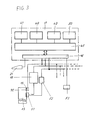
- the facilities shown in Figure 3 in the battery changing station 4 also comprise a computer or an electronic data processing device 17 which contains a microcomputer 45, an input / output unit 46 and memories 47 to 50.
- the memory 47 contains all the data of the batteries
- the memory 48 contains data about the individual charging locations 18 in the exchange station 4 and about the batteries currently stored in these charging locations 18,
- the memory 49 contains the driving orders that have not yet been carried out, and
- the memory 50 contains fixed data for the Routes and movements and regarding the load consumption.
- the computer 17 is connected to all the battery charging stations 18 in the battery changing station 4, four battery charging stations 18 of this type being present in the example shown. Depending on requirements, however, a different number of battery charging stations 18, for example eight, may also be arranged, or there may be several battery changing stations 4.
- Each of the battery charging stations 18 has a reading device 15 for reading the battery identification 36 arranged on the batteries. However, a central, fixed reading device can also be provided.
- the battery 13 is connected to the charger 16 and a current measuring device 52 via a coupling 51.
- the charger 16 supplies data about the charging process to the computer 12 and the current measuring device 52 is used to compare and monitor the state of charge of the battery 13.
- Each of the battery charging stations 18 is equipped with these devices.
- the computer 17 is also equipped with an interface 53, which is used to transmit data between the battery changing station 4, or its computer 17, and the transport vehicles 1, 2, or its computers 12, 22.
- the transport vehicle 2 is equipped with the charged battery 14, and at the same time the data for the travel order are transmitted to the transport vehicle 2 via the interfaces 53 and 44.
- This data is stored in the computer 22 and at the same time the identification of the battery 14 can be determined via the reading device 23.
- the commands are read from the memory 34 and it is determined whether these data also contain information about the required charge.
- the fixed requirement in the memory 35 is used to calculate and determine the charge requirement which must be taken from the battery 14 in order to carry out the read order. As soon as the charge requirement for executing the order is known, it is compared with the charge available and usable in the battery and it is determined whether the existing charge is sufficient for the execution of the order or not.
- the charge available from the battery 14 is determined by measuring the voltage when the vehicle 2 is stationary and comparing it with the fixed data available in the memory 32 of the computer 22. If, contrary to expectations, the charge stored in the battery 14 is not sufficient to execute the order, feedback is sent to the control station, and the transport vehicle 2 is again coupled to the battery changing station 4 and the battery 14 is replaced by another battery.
- the transport vehicle 2 now begins with the automatic execution of all driving, handling and transport commands.
- the voltage of the battery 14 is measured at intervals during the execution of the order.
- the distance traveled and the movements and transport processes carried out are determined and registered via the measuring device 42.
- the charge consumption for the movements and processes already carried out is calculated and accumulated.
- This cumulative value is continuously compared with the predetermined stored values, and if an excess is found, this information is stored in the memory 32 or 33 and examined during service checks. she can however, in a manner not shown, also serve to switch on an alarm stage which, if the charge in the battery 14 is removed too quickly, aborts the execution of the order and returns the transport vehicle 2 to the battery changing station 4. After each monitoring interval of charging the battery, it is checked whether the job has ended.
- the transport vehicle 2 automatically drives back to the battery changing station 4 in order to take over a new order. If the job has not yet ended, the job commands will continue to be executed until the job is completed. If the transport vehicle 2 returns to the battery changing station 4 after the order has been executed and the order has ended, the battery and movement data in the memories 33 and 35 are used to check whether the charge consumption has exceeded a certain size and the battery lasts longer than a minimum Target time was in use. If both limit values are exceeded, a battery change is initiated or a corresponding message is sent to the control station. This process is described in detail below. If the limit values are not exceeded, a new travel job is transmitted via the interface 44. The computer 22 again determines, as described above, whether the charge still present in the battery 14 is sufficient for the execution of this new order. If so, the transport vehicle 2 executes this order again.
- the continuous monitoring of the battery voltage described above also serves to determine a drop in the voltage or the charge of the battery below a minimum of 20% of the nominal capacity of the battery 14. When this value is reached, the order is canceled and the transport vehicle 2 returns to the battery changing station 4, regardless of whether an order has been completed or not. This is to prevent the battery 14 from being over-discharged.
- the service life of the batteries can be increased if they are operated with a lower depth of discharge and are not always discharged to the lowest permissible value of the charge. It is therefore advantageous if the battery 14 in the transport vehicle 2 is operated with a lower depth of discharge, for example in each case with a value x of 20% of the original nominal capacity of the battery, and is then recharged in each case.
- the cumulative calculated charge removal value and the values stored in the memories 32 or 33 are monitored and, when this 20% threshold is reached, the vehicle is determined for a battery change.
- this battery change is only carried out if the transport vehicle 2 was in use for the time y, for example at least two hours.
- a timing element is superimposed on these control elements, which is evaluated in combination with the cumulative charge removal values.
- the return trip to the exchange station 4 or to a control station is part of the order.
- the vehicle 2 is thus at the end of the order at the exchange station 4 or a control station. If the order is interrupted due to the voltage falling below the voltage limit or the minimum charge required, only the travel commands which lead back to the changing station 4 are carried out.
- the voltage is still monitored and the movement data are recorded. This until the exchange station 4 is reached. If the voltage of the battery falls below a second and lower limit value during the return trip, the vehicle 2 is stopped and the alarm device 43 is triggered. However, this is an exception and the vehicle 2 must then be brought back to the exchange station 4 using aids.
- the method according to the invention can be further explained with the aid of the flow chart shown in FIG.
- the identification code 36 which is attached to the battery 13 is read and at the same time the data stored in the transport vehicle 2 for the battery 13 are taken over by the computer 17 via the interface 53 and stored in the memory 47 .
- the duration of use is determined by means of a data comparison and a check is made as to whether the battery 13 has been in use for more than one hour or not. If this is the case, it is released for charging.
- the operating time is less than one hour, it is determined in the example described based on the historical data of this battery 13 whether the past five last uses (value x) were all less than one hour (value z). Depending on the battery type and operating conditions, other values of these limit conditions can be used. If the specified limit values are reached, the battery is considered old and no longer suitable for further use in this transport system. The battery 13 recognized as unusable is then removed from the battery changing station 4 and a new battery is inserted and charged in its place in the changing station 4. At the same time, all battery data of this battery 13 are deleted. If less than five consecutive uses were less than an hour, the battery can be recharged again because short operations can also be generated by extreme loads, ie high load consumption.
- the battery 13 Before charging the battery 13, it is therefore checked whether one of the other batteries, which is located in the battery charging stations 18, is already being charged with a recharging cycle. If this is the case, the battery 13 is charged and released as soon as it is required for a change process. If no other battery is charged with a cycle with a recharging phase, a list in the battery data memory 47 is used to check whether the battery 13 needs to be recharged. This is the case if it is not yet entered in this list of batteries that have already been recharged. After completion of the recharge, the battery 13 is also entered in this list. As soon as all operational batteries have been registered in the list, ie once they have been recharged, the list is deleted and the registration process starts again. Batteries that have been removed are immediately deleted from the list.
- This list check ensures that each battery is recharged in one cycle. If the battery 13 is released for a charging cycle with recharging, it is blocked in the battery changing station 4 until this charging with the recharging phase has been carried out completely. During this time, only the batteries stored in the other three battery charging stations 18 are available for battery changing processes between the battery changing station 4 and the transport vehicles 1 and 2. During the further changing processes, the battery that has the longest dwell time in the battery changing station 4 is output.
- this type of monitoring of the battery 14 on the transport vehicle 2 ensures a high level of operational safety and thus trouble-free operation of the entire transport system.
- the number of transport vehicles used is not limited since, depending on requirements, a larger number of charging locations 18 can be arranged in the battery changing station 4 or several battery changing stations 4.
- Monitoring the batteries in the vehicles and carrying out the battery replacement in accordance with the invention enables the optimum use of the possible battery life and thus an increase in the economy of the system.
Abstract
Description
Die Erfindung betrifft ein Verfahren zum Ueberwachen und Steuern des Lade-/Entladevorganges und des Batteriewechsels von auswechselbaren Batterien bei einem elektrisch angetriebenen Transport- und Handlingfahrzeug welches Teil eines im Dauerbetrieb arbeitenden, mindestens teilweise automatischen Transportsystemes ist, wobei im Transportsystem eine Batteriewechselstation mit mehreren Ladeeinrichtungen vorhanden ist und diese Wechselstation vom Transportfahrzeug angefahren wird, die Batterien in dieser Wechselstation ausgetauscht und aufgeladen werden, im Transportfahrzeug und in der Wechselstation mittels elektronischer Datenverarbeitungseinrichtungen Betriebsdaten gespeichert sind und erfasst werden und dem Transportfahrzeug über eine Leitstation Aufträge, insbesondere Fahr-, Transport- und Handlingaufträge übermittelt werden sowie eine Vorrichtung zum Steuern des Lade-/Entladevorganges und des Batteriewechsels von auswechselbaren Batterien bei elektrisch angetriebenen Transportfahrzeugen eines im Dauerbetrieb arbeitenden Transportsystemes.The invention relates to a method for monitoring and controlling the charging / discharging process and the battery change of replaceable batteries in an electrically powered transport and handling vehicle which is part of a continuously operating, at least partially automatic transport system, a battery changing station with several charging devices being present in the transport system is and this exchange station is approached by the transport vehicle, the batteries are exchanged and charged in this exchange station, operating data are stored and recorded in the transport vehicle and in the exchange station by means of electronic data processing devices and orders, in particular driving, transport and handling orders, are conveyed to the transport vehicle via a control station are transmitted as well as a device for controlling the charging / discharging process and the battery change of replaceable batteries in an electrically driven transport create a transport system working in continuous operation.
Bei automatischen Transportsystemen, welche beispielsweise in automatischen Fabrikationsanlagen oder in Textilverarbeitungsanlagen Einsatz finden, werden üblicherweise zur Beförderung von Waren oder Warenbehältern fahrerlose Transportfahrzeuge mit einer automatischen Steuerung eingesetzt. Diese Transportfahrzeuge sind sehr oft mit elektrischen Antrieben ausgestattet, welche ihre Antriebsenergie aus elektrischen Batterien, bzw. Akkumulatoren beziehen. Es ist bekannt, bei Transportfahrzeugen entladene Batterien auszuwechseln und in einer Ladestation wieder aufzuladen. Um die Wirtschaftlichkeit derartiger Transportsysteme zu gewährleisten ist es notwendig, den Einsatz der Fahrzeuge und der Batterien zu optimieren.In automatic transport systems, which are used, for example, in automatic manufacturing plants or in textile processing plants, driverless transport vehicles with an automatic control are usually used for the transport of goods or goods containers. These transport vehicles are very often equipped with electrical drives, which draw their drive energy from electrical batteries or accumulators. It is known to replace discharged batteries in transport vehicles and to recharge them in a charging station. In order to ensure the economy of such transport systems, it is necessary to optimize the use of the vehicles and the batteries.
Es ist bereits ein Managementsystem für batteriebetriebene Flurförderzeuge bekannt, welches über einen Rechner, bzw. eine Datenverarbeitungs- einrichtung für die Bewirtschaftung der Batterien und der Fahrzeuge verfügt und für den Einsatz im Mehrschichtbetrieb bestimmt ist. Bei diesem bekannten System ist eine Batterieladestation vorhanden, welche mehrere Batterien enthält und als Batteriepool dient. Die Fahraufträge für die Transportfahrzeuge werden vom Rechner verarbeitet, und es wird ermittelt, welcher Ladungsanteil einer Batterie verbraucht wird um einen bestimmten Fahrauftrag ausführen zu können. Mit Hilfe von gespeicherten Batterieladungsdaten ermittelt der Rechner, welche Batterie eine genügend grosse Ladung aufweist, um einem Transportfahrzeug die nötige Energie abgeben zu können. Diese Batterie wird dann in ein Transportfahrzeug übergeben, und das Fahrzeug führt mit Hilfe eines Fahrzeugrechners und einer entsprechenden Steuerung den Auftrag aus. Nach Ausführung des Fahrauftrages wird die Batterie wieder in die Ladestation übernommen und aufgeladen. Die Datenverarbeitungseinrichtung der Ladeeinrichtung enthält dabei für jede Batterie eine Datei, in welcher Ladung, Leistungsentwicklung und Alterung festgehalten werden. Die in der Ladeeinrichtung vorhandenen Batterien werden nur für Fahraufträge eingesetzt, für welche ihre Leistungsfähigkeit genügend ist. Leistungsschwache Batterien werden einer Reservegruppe zugeordnet und bei Unterschreiten eines Leistungsgrenzwertes ausgeschieden. Ein Nachteil dieses Systemes besteht darin, dass die Fahrzeuge nach jedem Fahrauftrag zur Ladestation zurückkehren und die Batterie, unabhängig vom Ladungszustand, ausgewechselt wird. Dadurch erfolgen Batteriewechsel auch, wenn das Fahrzeug noch weitere Fahraufträge ausführen könnte. Im weiteren muss in der Ladestation, welche als Pool dient, Platz für sämtliche Batterien vorhanden sein, da sonst die Zuteilung zu den Fahrzeugen erschwert wird, oder eventuell ein bestimmter Fahrauftrag nicht ausgeführt werden kann, da die verfügbaren Fahrzeuge und Batterien nicht zueinander passen. Ein weiterer Nachteil besteht darin, dass an der Ladestation, bzw. am Batteriepool eine Warteschlange von Transportfahrzeugen besteht, bis alle Batterien an die entsprechenden Fahrzeuge zugeteilt sind. Dies hat unproduktive Stillstandszeiten zur Folge und ein vollständig kontinuierlicher Ablauf ist nicht möglich.A management system for battery-operated industrial trucks is already known, which has a computer or a data processing device for the management of the batteries and the vehicles and is intended for use in multi-shift operation. In this known system there is a battery charging station which contains several batteries and serves as a battery pool. The driving orders for the transport vehicles are processed by the computer and it is determined which portion of the charge of a battery is consumed in order to be able to carry out a specific driving order. With the help of stored battery charge data, the computer determines which battery has a sufficiently large charge to be able to deliver the necessary energy to a transport vehicle. This battery is then transferred to a transport vehicle, and the vehicle executes the order with the help of a vehicle computer and a corresponding control. After the driving order has been carried out, the battery is transferred back to the charging station and charged. The data processing device of the charging device contains a file for each battery, in which charge, power development and aging are recorded. The batteries in the charging device are only used for driving jobs for which their performance is sufficient. Low-performance batteries are assigned to a reserve group and are discarded if the performance limit falls below. A disadvantage of this system is that the vehicles return to the charging station after each driving order and the battery is replaced regardless of the charge status. As a result, the batteries are changed even if the vehicle could carry out further driving orders. Furthermore, there must be space for all batteries in the charging station, which serves as a pool, as otherwise the allocation to the vehicles will be difficult, or a certain driving order may not be possible because the available vehicles and batteries do not match. Another disadvantage is that there is a queue of transport vehicles at the charging station or at the battery pool until all batteries have been allocated to the corresponding vehicles. This results in unproductive downtimes and a completely continuous process is not possible.
Es ist Aufgabe der vorliegenden Erfindung, ein Verfahren und eine Vorrichtung zu schaffen, mittels welchen elektrisch betriebene Transportfahrzeuge möglichst störungsfrei in einem im Dauerbetrieb arbeitenden automatischen Transportsystem eingesetzt werden können, das System mit einem oder mehreren Transportfahrzeugen betrieben werden kann, ohne dass beim Einsatz mehrerer Fahrzeuge störende Warteschlangen entstehen, im weiteren die Ladung und Entladung und das Auswechseln der Batterien so erfolgt, dass eine optimale Lebensdauer der Batterien erreicht wird, sowie verhindert wird, dass Batterien tiefentladen werden und alle noch einsatzfähigen Batterien regelmässig nachgeladen werden und nicht einsatzfähige oder alte Batterien erkannt und soweit nötig ausgeschieden werden.It is an object of the present invention to provide a method and a device by means of which electrically operated transport vehicles can be used as trouble-free as possible in an automatic transport system operating in continuous operation, the system can be operated with one or more transport vehicles without using multiple vehicles Disturbing queues arise, furthermore the charging and discharging and the replacement of the batteries take place in such a way that an optimal service life of the batteries is achieved, as well as it is prevented that batteries are deeply discharged and all batteries that are still operational are regularly recharged and non-operational or old batteries are recognized and be eliminated as necessary.
Diese Aufgabe wird bei einem Verfahren nach dem Oberbegriff des Patentanspruches 1 erfindungsgemäss durch die kennzeichnenden Merkmale dieses Patentanspruches und bei einer Vorrichtung nach dem Oberbegriff des Patentanspruches 11 nach den kennzeichnenden Merkmalen dieses Patentanspruches 11 gelöst. Vorteilhafte Weiterbildungen der Erfindung ergeben sich nach den Merkmalen der abhängigen Patentansprüche.This object is achieved according to the invention in a method according to the preamble of
Mit dem erfindungsgemässen Verfahren werden verschiedene Vorteile erzielt. Die Ueberwachung der Batteriespannung und die Ermittlung des Ladezustandes der Batterien auf dem oder den Transportfahrzeugen ermöglicht es zu erkennen, wenn eine Batterie zu stark entladen wird und die Gefahr einer Tiefentladung besteht oder die Batterie so stark entladen wird, dass ein Fahrauftrag nicht mehr ausgeführt werden kann. Sobald eine zu tiefe Entladung der Batterie erkannt wird, wird die Ausführung des Auftrages des entsprechenden Transportfahrzeuges unterbrochen und falls dies ohne Gefahr der Tiefentladung noch möglich ist, automatisch zur Batteriewechselstation zurückgefahren oder das Fahrzeug wird gestoppt, Alarm ausgelöst und das Rückfahren erfolgt mit Hilfsmitteln. Dadurch wird verhindert, dass das Transportfahrzeug irgendwo auf dem Transportweg stehenbleibt und Störungen im gesamten Transportsystem auftreten. In der Batteriewechselstation wird bei der Uebernahme die entladene Batterie mit Hilfe eines Identifizierungscodes erkannt und aufgrund von Erfahrungswerten und den für diese Batterie abgespeicherten Betriebsdaten, wie zum Beispiel Einsatzzeiten, entnommene Ladung, festgestellt, ob es sich eventuell um eine alte oder nicht mehr einsatzfähige Batterie handelt welche ausgeschieden werden sollte. Ist dies der Fall, so wird die Batterie nicht mehr aufgeladen sondern ausgeschieden und durch eine einsatzfähige Batterie ersetzt. Andernfalls erfolgt ein Aufladevorgang der Batterie. Da in der Wechselstation mehrere Batterien vorhanden sind, kann mindestens eine Batterie einem Ladevorgang mit Nachladung unterzogen werden. Bei derartigen Ladevorgängen mit Nachladung wird die Sulfatisierung rückgängig gemacht, was eine Verlängerung der Lebensdauer der Batterie zur Folge hat. Während dieses Ladevorganges mit Nachladung steht diese Batterie nicht für Batteriewechsel zur Verfügung, sondern die Batteriewechsel werden mit den anderen in der Wechselstation vorhandenen Batterien ausgeführt.Various advantages are achieved with the method according to the invention. The Ueberwac The battery voltage and the determination of the state of charge of the batteries on the transport vehicle (s) make it possible to detect when a battery is being over-discharged and there is a risk of deep discharge or the battery is being discharged to such an extent that a driving order can no longer be carried out. As soon as a too deep discharge of the battery is detected, the execution of the order of the corresponding transport vehicle is interrupted and, if this is still possible without the risk of deep discharge, the vehicle is automatically returned to the battery changing station or the vehicle is stopped, the alarm is triggered and the return is carried out with aids. This prevents the transport vehicle from stopping somewhere on the transport route and faults occurring in the entire transport system. In the battery change station, the discharged battery is identified with the help of an identification code and, based on empirical values and the operating data stored for this battery, such as operating times, the charge removed, it is determined whether it is an old or no longer usable battery which should be eliminated. If this is the case, the battery is no longer charged, but is eliminated and replaced by an operational battery. Otherwise the battery is charged. Since there are several batteries in the exchange station, at least one battery can be charged with recharging. In such charging processes with recharging, the sulfation is reversed, which results in an extension of the battery life. During this charging process with recharging, this battery is not available for battery replacement, but the battery replacement is carried out with the other batteries in the exchange station.
Ein weiterer Vorteil besteht darin, dass die Batterien auf dem Transportfahrzeug verbleiben bis ein bestimmter Spannungs-, bzw. Ladungsgrenzwert erreicht ist oder die verfügbare Ladung der Batterie für die Ausführung eines Auftrages nicht mehr genügt. Dies wird dadurch sichergestellt, dass die Spannung der Batterie auf dem Fahrzeug bei Stillstand des Fahrzeuges in Intervallen gemessen und abgespeichert wird. Mit Hilfe von bekannten Werten welche einer bestimmten Messspannung eine bestimmte Ladung zuordnen lässt sich der Ladungszustand der Batterie jederzeit feststellen. Erhält nun das Fahrzeug einen neuen Fahrauftrag, so wird über die Datenverarbeitungseinrichtung in der Wechselstation oder im Transportfahrzeug oder einer speziellen Leitstation ebenfalls mit Hilfe von Festdaten, welche aus Erfahrungswerten gebildet sind, die für die Durchführung des Auftrages benötigte Ladung ermittelt. Ist diese kleiner als die in der Batterie noch vorhandene Ladung, so kann der Auftrag ausgeführt werden. Andernfalls wird die Batterie in der Batteriewechselstation ausgetauscht und wieder aufgeladen. Das Transportfahrzeug verfügt über gespeicherte Daten, welche die Ausführung von Fahr-, Bewegungs- und Transportaufträgen ermöglichen und soweit nötig auch die dafür benötigten Energiemengen beinhalten. Im weiteren ist die Datenverarbeitungseinrichtung des Transportfahrzeuges jederzeit in der Lage, einen korrekten Rückfahrweg zur Batteriewechselstation zu ermitteln und die entsprechenden Steuerbefehle an die Fahrzeugsteuerung zu übermitteln.Another advantage is that the batteries remain on the transport vehicle until a certain voltage or charge limit is reached or the available charge of the battery is no longer sufficient for the execution of an order. This is ensured by the fact that the voltage of the battery on the vehicle is measured and stored at intervals when the vehicle is stationary. The charge state of the battery can be determined at any time using known values which assign a specific charge to a specific measurement voltage. If the vehicle now receives a new travel order, the data required in the exchange station or in the transport vehicle or a special control station is also used to determine the charge required to carry out the order using fixed data which are formed from empirical values. If this is smaller than the charge still present in the battery, the job can be carried out. Otherwise the battery in the battery changing station will be replaced and recharged. The transport vehicle has stored data that enable the execution of travel, movement and transport orders and, if necessary, also contain the required amounts of energy. Furthermore, the data processing device of the transport vehicle is able at all times to determine a correct return path to the battery changing station and to transmit the corresponding control commands to the vehicle control system.
Das erfindungsgemässe System und Verfahren ermöglicht auch die zusätzliche Optimierung der Lade- und Entlade- sowie Auswechselvorgänge der Batterien, indem auf jedem Transportfahrzeug die ausgeführten Fahr-, Handling- und Transportbewegungen durch den Fahrzeugrechner erfasst, und mit Hilfe dieser Daten der Ladungsverbrauch ermittelt wird. Dieser Ladungsverbrauch kann nun über verschiedene Transport-, Handlings- und Bewegungsvorgänge kumuliert werden und entspricht der aus der Batterie entnommenen Ladung. Der Vorteil besteht nun darin, dass bei einem vorgegebenen Grenzwert für den ermittelten Ladungsverbrauch das Transportfahrzeug zur Wechselstation zurückgefahren und die Batterie ausgewechselt und aufgeladen wird. Dadurch lässt sich ein zyklisches Auf- und Entladen der Batterie erreichen, ohne dass die Batterie gegen den Bereich der Tiefentladung entladen wird. Durch das Ueberlagern einer minimalen Einsatzzeitbedingung in Kombination mit der Bedingung einer minimalen entnommenen Ladung wird trotzdem eine vorteilhafte optimale Einsatzdauer der Batterien erwirkt.The system and method according to the invention also enable the charging, discharging and replacement processes of the batteries to be additionally optimized by recording the driving, handling and transport movements carried out by the vehicle computer on each transport vehicle and using these data to determine the charge consumption. This charge consumption can now be accumulated via various transport, handling and movement processes and corresponds to the charge removed from the battery. The advantage now lies in the fact that the transport vehicle is moved back to the change station and the battery is replaced and charged at a predetermined limit value for the determined charge consumption. As a result, the battery can be charged and discharged cyclically without the battery being discharged against the area of deep discharge. By superimposing a minimum operating time condition in combination with the condition of a minimal charge removed, an advantageous optimal operating time of the batteries is nevertheless achieved.
Besonders vorteilhaft ist, dass mit relativ geringem Aufwand die Ueberwachung der Batterie auf dem Transportfahrzeug und in der Wechselstation erfolgt, und sich dadurch die Möglichkeit eröffnet, die Batterien optimal einzusetzen. Die Transportfahrzeuge können durchgehend im Einsatz stehen, womit ein automatischer 24-Stunden-/ 7-Tage-Betrieb gewährleistet werden kann und erhebliche Einsparungen an Investitionskosten möglich sind. Die einzelnen Transport- und Bewegungsaufträge können an Fahrzeuge übermittelt werden, welche mit einer aufgeladenen Batterie bestückt sind oder auch an Fahrzeuge, welche bereits im Transportsystem integriert sind und noch über eine genügende Ladung der Batterie verfügen. Diese Einsatzart gewährleistet, dass die Fahrzeuge optimal eingesetzt sind und möglichst wenige Batteriewechsel notwendig werden.It is particularly advantageous that the battery is monitored on the transport vehicle and in the changing station with relatively little effort, and this opens up the possibility of optimally using the batteries. The transport vehicles can be used all the time, which guarantees automatic 24-hour / 7-day operation and considerable savings in investment costs are possible. The individual transport and movement orders can be transmitted to vehicles that are equipped with a charged battery or to vehicles that are already integrated in the transport system and still have sufficient battery charge. This type of application ensures that the vehicles are used optimally and that as few battery changes as possible are necessary.
Im folgenden werden die Erfindung sowie weitere Vorteile und Einzelheiten anhand von Ausführungsbeispielen unter Bezugnahme auf die beiliegenden Zeichnungen näher erläutert. Es zeigen:
- Fig. 1 einen Ausschnitt aus einem automatischen Transportsystem in schematischer Darstellung
- Fig. 2 ein Blockschaltbild der Ueberwachungseinrichtungen auf dem Transportfahrzeug
- Fig. 3 ein Blockschaltbild der Ueberwachungs- und Steuereinrichtungen in der Batteriewechselstation
- Fig. 4 einen Ablaufplan der Verfahrensschritte zur Ueberwachung der Batterie im Transportfahrzeug und
- Fig. 5 einen Ablaufplan der Verfahrensschritte zum Laden und Wechseln der Batterien in der Batteriewechselstation.
- Fig. 1 shows a section of an automatic transport system in a schematic representation
- Fig. 2 is a block diagram of the monitoring devices on the transport vehicle
- Fig. 3 is a block diagram of the monitoring and control devices in the battery changing station
- Fig. 4 is a flowchart of the method steps for monitoring the battery in the transport vehicle and
- 5 shows a flowchart of the method steps for charging and changing the batteries in the battery changing station.
Der in Figur 1 dargestellte Ausschnitt aus einem automatischen Transportsystem zeigt einen Teil einer Fabrikationsanlage zur Bearbeitung von textilen Materialien. Solche Fabrikationsanlagen werden häufig im Dauerbetrieb betrieben, d.h. 24 Stunden im Tag und 7 Tage in der Woche. Eine gesamte Anlage umfasst eine Vielzahl von Maschinen, Bearbeitungs- und Lagerstellen, wobei in Figur 1 nur einige wenige gezeigt sind. Auf einer Fahrspur 3 bewegen sich automatisch gesteuerte Transportfahrzeuge 1 und 2, wobei in der ganzen Anlage auch noch weitere Fahrzeuge vorhanden sein können, oder bei einer kleinen Anlage nur ein einzelnes Fahrzeug vorgesehen ist. Die Fahrspur 3 wird dabei an Spinnereivorwerksmaschinen vorbeigeführt, nämlich Karden 5 und Strecken 6. Zwischen diesen Karden 5 und Strecken 6 müssen Transportbehälter 7, 8 ausgetauscht werden, welche dem Transport von Textilmaterial dienen. Die Fahrspur 3 hat noch weitere Aeste, welche dem Transport der Transportbehälter 7, 8 zu weiteren Maschinen und Lagerplätzen dieses Spinnereibetriebes dienen. Der Transport der Behälter 7, 8 erfolgt mittels der Transportfahrzeuge 1, 2, welche elektrisch angetrieben sind. Für die Energieversorgung des elektrischen Antriebes ist jedes Transportfahrzeug 1, 2 mit einer Batterie 10, 13 ausgestattet. Im weiteren befinden sich auf jedem Fahrzeug 1, 2 noch eine Leseeinrichtung 11, 23 für die Batteriekennzeichnung, eine Handlingeinrichtung 9 für das Umsetzen der Transportbehälter 7, 8 sowie die Durchführung von weiteren Aufgaben und ein Computer 12, 22, bzw. eine elektronische Datenverarbeitungseinrichtung. Im weiteren verfügen die Transportfahrzeuge 1, 2 über nicht dargestellte Antriebs- und Lenkeinrichtungen sowie eine Fahrsteuerung, welche auch das Erkennen und Abfahren der Fahrspur 3 sicherstellt.The section of an automatic transport system shown in FIG. 1 shows part of a manufacturing system for processing textile materials. Such manufacturing plants are often operated continuously, i.e. 24 hours a day and 7 days a week. An entire system comprises a large number of machines, processing and storage locations, only a few being shown in FIG. 1. Automatically controlled
An einem geeigneten Platz neben der Fahrspur 3 befindet sich eine Batteriewechselstation 4. Diese verfügt über mehrere, im gezeigten Beispiel vier, Batterieladeplätze 18. Zu jedem Batterieladeplatz 18 gehört ein Ladegerät 16 und eine Leseeinrichtung 15 für die Erkennung des Identifizierungscodes an jeder Batterie. Im weiteren sind nicht dargestellte Kupplungseinrichtungen und Handlingeinrichtungen für die Batterien sowie eine elektrische Stromversorgung vorhanden. Die Ueberwachung und Steuerung der Batteriewechselstation 4 erfolgt mit Hilfe eines Computers, bzw. einer elektronischen Datenverarbeitungseinrichtung 17. Im dargestellten Beispiel ist die Batteriewechselstation 4 als horizontale drehbare Scheibe ausgebildet, welche in Richtung der Pfeile 19 schwenkbar ist.At a suitable place next to the
Im dargestellten Beispiel befindet sich das Transportfahrzeug 2 in einer genau definierten Wechselposition neben der Batteriewechselstation 4. Ueber eine nicht dargestellte lösbare Verbindung sind die beiden Computer 22 des Transportfahrzeuges 2 und der Computer 17 der Batteriewechselstation 4 miteinander verbunden. Die Batterie 13 in der Batteriewechselstation 4 wurde aus dem Transportfahrzeug 2 mit Hilfe von nicht dargestellten Handlingeinrichtungen automatisch entnommen. Gleichzeitig wurde mittels der Leseeinrichtung 15 der Identifizierungscode der Batterie 13 abgelesen und die Betriebsdaten der identifizierten Batterie 13 im Computer 17 abgespeichert. Die Batterie 13 ist entladen und muss normal geladen oder geladen und nachgeladen werden. Nun wird in der Wechselstation 4 die günstigste einsatzfähige Batterie bestimmt und ausgegeben. Im dargestellten Beispiel ist dies die Batterie 14. Die Batteriewechselstation 4 wird um 90 verschwenkt, so dass die Batterie 14 vor dem Batteriefach des Transportfahrzeuges 2 positioniert ist. Diese aufgeladene Batterie 14 wird jetzt in das Transportfahrzeug 2 geschoben und hier die elektrische Verbindung wieder hergestellt. Alle Betriebsdaten dieser Batterie 14 werden im Computer 22 wiederum erfasst solange sich die Batterie 14 im Transportfahrzeug 2 befindet. Ist diese Batterie 14 nach einem oder mehreren Transport-, Handling- und Arbeitsvorgängen des Transportfahrzeuges 2 soweit entladen, dass sie ausgetauscht werden muss, so können die ermittelten Betriebsdaten dieser Batterie 14 und die mit ihr ausgeführten Bewegungsvorgänge beim Wechselvorgang der Batterie über die Kommunikationsschnittstelle vom Computer 22 in den Computer 17 der Batteriewechselstation übernommen werden. Die Batteriewechselstation 4 ist im weiteren mit einer Ein-/Ausgabeeinheit 21 ausgestattet, über welche Steuerbefehle manuell eingegeben werden können. Ueber diese Ein-/Ausgabeeinheit 21 können auch die Fahr- und Arbeitsbefehle für die Transportfahrzeuge 1 und 2 in das Transportsystem eingespeist werden. Es sind aber auch andere bekannte Uebertragungsmöglichkeiten denkbar, wie zum Beispiel Infrarotsender.In the example shown, the
Figur 2 zeigt in einem Blockschaltbild diejenigen Mittel, welche zusätzlich zu den bekannten Einrichtungen auf den Transportfahrzeugen 1, 2 vorhanden sind um die Funktionsfähigkeit des erfindungsgemässen Transportsystemes zu gewährleisten. Der Computer 12 besteht aus einem bekannten Mikrocomputer- 30, bzw. einer Prozess-Steuereinrichtung. Dieser Mikrocomputer 30 ist mit einer Eingangs-/Ausgangseinheit 31 und verschiedenen Datenspeichern 32 bis 35 verbunden. Der Speicher 32 enthält Festdaten über die im Fahrzeug eingesetzte Batterie 10, insbesondere über den Zusammenhang des Ladungszustandes in Abhängigkeit von der Messspannung der Batterie. Im Speicher 33 werden diejenigen Batteriedaten abgelegt, welche laufend während des Betriebes des Transportfahrzeuges ermittelt werden. Es handelt sich dabei insbesondere um die momentane Ladungsmenge der Batterie, die der Batterie entnommene Ladung, den Uebernahmezeitpunkt der Batterie und die bereits ausgeführten Bewegungen des Fahrzeuges. Im Speicher 34 sind die Auftragsdaten enthalten, welche vor Beginn des Transportauftrages an das Transportfahrzeug übergeben wurden. Mit Hilfe dieser Daten folgt das Transportfahrzeug 1 der Fahrspur 3 und führt an den Maschinen 5, 6 die gewünschten Wechsel- und Bedienungsaufträge aus. Im Speicher 35 befinden sich Festdaten über die Fahrspur 3 sowie die Wechsel-und Handhabungsaufgaben, welche an den Maschinen 5 und 6 auszuführen sind. Diese Daten beinhalten unter anderem auch den Energie-, bzw. Ladungsverbrauch für die einzelnen Arbeitsschritte, so dass der Rechner 12 aufgrund der Fahrauftragsdaten den Ladungsverbrauch aus der Batterie ermitteln kann.FIG. 2 shows in a block diagram those means which are present on the
Mit dem Computer 12 verbunden ist eine Spannungs-Messeinrichtung 39, welche über eine elektrische Kupplung 37 mit den Batterieanschlüssen verbunden ist. Ueber diese elektrische Kupplung 37 wird mittels der Spannungs-Messeinrichtung 39 die Spannung der Batterie 10 gemessen. Die Messung erfolgt bei stillstehendem Fahrzeug, z.B. in einer Leitstation oder an einer Maschine, aber auch bei arbeitendem Fahrzeug. Die Auswertung der Messung ist jeweils unterschiedlich, bzw. erfolgt mit anderen Vergleichsdaten. Die Batterie 10 ist mit einem Identifizierungscode 36 versehen, zum Beispiel mit einem Strichcode oder einer anderen bekannten Kennzeichnungseinrichtung. Dieser Kennzeichnungscode 36 dient der Kennzeichnung jeder einzelnen Batterie, so dass jede Batterie mit den Leseeinrichtungen 11 identifiziert werden kann. Ein Antriebsmotor 38 und eventuell weitere Antriebe beziehen über die Kupplung 37 elektrischen Strom von der Batterie 10 und sind anderseits über eine Fahrsteuerung 40 wiederum mit dem Rechner 12 verbunden. Die Fahrsteuerung 40 ist mit einem Spurleser 41 ausgestattet, welcher in bekannter Weise auf optischem, induktivem oder auf anderem Wege die zu verfolgende Fahrspur erkennen kann. Die eigentlichen Daten für die abzufahrende Strecke, d.h. die entsprechenden Steuerbefehle, erhält die Fahrsteuerung 40 vom Computer 12. Im weiteren ist eine Messeinrichtung 42 für den zurückgelegten Weg des Transportfahrzeuges, welche mit nicht dargestellten Sensoren ausgestattet ist, vorhanden. Der Computer 12 erkennt und registriert die Bewegungen des Fahrzeuges und der Handlingeinrichtungen. Als Sicherheitseinrichtung verfügt der Computer 12 über eine Alarmeinrichtung 43, welche anspricht, wenn das Transportfahrzeug 1, 2 aus irgend einem Grunde den automatischen Transportauftrag nicht ausführen kann. Eine Schnittstelle 44 dient der Verbindung des Computers 12 und der mit dem Computer 12 verbundenen anderen Einrichtungen mit Einrichtungen ausserhalb der Transportfahrzeuge 1, 2. Im dargestellten Beispiel dient die Schnittstelle 44 auch als Empfangs- und Uebergabestelle für die Fahrbefehle und für die Betriebsdaten der Batterie. Diese Kombination von Einrichtungen und einem mit den geeigneten Speichern ausgestatteten Mikrocomputer erlaubt den Fahrzeugen 1, 2, ihre Fahr-, bzw. Transportaufträge vollständig autonom auszuführen. Das mit diesen Einrichtungen ausgeführte erfindungsgemässe Betriebsverfahren ermöglicht durch die laufende Ueberwachung der Spannung der Batterien, bzw. deren Ladung und die Ueberwachung aller Fahr-, Transport- und Handlingbewegungen einen Betrieb mit sehr hoher Sicherheit. Unterschreitet die Restladung der Batterie 10 einen Grenzwert, welcher im vorliegenden Beispiel mit 20 % der Nennkapazität festgelegt ist, so wird das Fahrzeug automatisch angehalten und, falls dies ohne Gefahr einer Tiefentladung möglich ist, zur Batteriewechselstation zurückgefahren. Andernfalls wird das Fahrzeug gestoppt und über die Alarmeinrichtung 43 Alarm ausgegeben. Parallel werden durch die Einrichtung 42 und den Computer 12 alle Bewegungen registriert und mit Hilfe der im Speicher 35 vorhandenen Daten die theoretisch verbrauchte Ladung ermittelt. Im weiteren wird die Batterie für den Austausch vorgemerkt, wenn die durch den Computer 12 ermittelte und der Batterie entnommene Ladung einen Minimalwert, welcher im vorliegenden Beispiele mit 20 % der Nennkapazität der neuen Batterie festgelegt ist, überschreitet. Es kann zweckmässig sein, diesem Minimalwert der Ladung noch eine minimale Einsatzdauer der Batterie zu überlagern, d.h. die Batterie wird nur ausgewechselt, wenn z.B. die Einsatzdauer mindestens zwei Stunden war. Das Fahrzeug wird dann automatisch zur Batteriewechselstation zurückgefahren.A
Die in Figur 3 dargestellten Einrichtungen in der Batteriewechselstation 4 umfassen ebenfalls einen Computer, bzw. eine elektronische Datenverarbeitungseinrichtung 17, welcher einen Mikrocomputer 45, eine Eingangs-/Ausgangseinheit 46 und Speicher 47 bis 50 enthält. Der Speicher 47 enthält alle Daten der Batterien, der Speicher 48 Daten über die einzelnen Ladeplätze 18 in der Wechselstation 4 und über die momentan in diesen Ladeplätzen 18 eingelagerten Batterien, der Speicher 49 enthält die noch nicht ausgeführten Fahraufträge, und der Speicher 50 Festdaten zu den Fahrwegen und Bewegungsabläufen und betreffend den Ladungsverbrauch. Der Computer 17 ist mit allen Batterieladeplätzen 18 in der Batteriewechselstation 4 verbunden, wobei im dargestellten Beispiel vier derartige Batterieladeplätze 18 vorhanden sind. Je nach Bedarf kann jedoch auch eine andere Zahl von Batterieladeplätzen 18, zum Beispiel acht, angeordnet sein, oder es können mehrere Batteriewechselstationen 4 vorhanden sein. Jeder der Batterieladeplätze 18 verfügt über eine Leseeinrichtung 15 zum Lesen der an den Batterien angeordneten Batteriekennzeichnung 36. Es kann aber auch eine zentrale, feststehende Leseeinrichtung vorgesehen sein. Ueber eine Kupplung 51 ist die Batterie 13 mit dem Ladegerät 16 und einer Strommesseinrichtung 52 verbunden. Das Ladegerät 16 liefert Daten über den Ladeverlauf an den Computer 12 und die Strommesseinrichtung 52 dient dem Vergleich und der Ueberwachung des Ladungszustandes der Batterie 13. Jeder der Batterieladeplätze 18 ist mit diesen Einrichtungen ausgerüstet. Ergänzend ist der Computer 17 noch mit einer Schnittstelle 53 ausgestattet, welche der Uebermittlung von Daten zwischen der Batteriewechselstation 4, bzw. deren Computer 17 und den Transportfahrzeugen 1, 2, bzw. deren Computern 12, 22 dient. Zusätzlich ist eine Ein-/Ausgabeeinrichtung 21 für Daten vorhanden, über welche manuell oder automatisch Ueberwachungs-, Steuer- oder andere Daten in den Computer 17 eingegeben und/oder über die Schnittstelle 53 an die Transportfahrzeuge 1, 2 übermittelt und dort abgespeichert werden können.The facilities shown in Figure 3 in the battery changing station 4 also comprise a computer or an electronic
Die Durchführung des erfindungsgemässen Verfahrens soll nun anhand der in den Figuren 4 und 5 dargestellten Ablaufpläne mit Bezug auf die Figuren 1, 2 und 3 näher erläutert werden. Wie vorne zu Figur 1 erläutert, wird das Transportfahrzeug 2 mit der aufgeladenen Batterie 14 bestückt, und gleichzeitig werden über die Schnittstellen 53 und 44 die Daten für den Fahrauftrag an das Transportfahrzeug 2 übermittelt. Diese Daten werden im Computer 22 gespeichert und gleichzeitig kann über die Leseeinrichtung 23 die Kennzeichnung der Batterie 14 festgestellt werden. Sobald der Batteriewechselvorgang vollständig abgeschlossen ist und die Batteriewechselstation 4 das Transportfahrzeug 2 freigibt, führt dieses Transportfahrzeug 2 den übermittelten Auftrag autonom aus. Als erstes werden die Befehle aus dem Speicher 34 eingelesen und festgestellt, ob diese Daten auch Angaben über den benötigten Ladungsbedarf enthalten. Ist der Ladungsbedarf nicht bekannt, so wird mit Hilfe der Festdaten im Speicher 35 der Ladungsbedarf, welcher der Batterie 14 entnommen werden muss um den eingelesenen Auftrag auszuführen errechnet und festgestellt. Sobald der Ladungsbedarf zur Ausführung des Auftrages bekannt ist, wird dieser mit der in der Batterie vorhandenen und nutzbaren Ladung verglichen und festgestellt, ob die vorhandene Ladung für die Ausführung des Auftrages genügt oder nicht. Die Ermittlung der aus der Batterie 14 verfügbaren Ladung erfolgt durch Messen der Spannung im Stillstand des Fahrzeuges 2 und Vergleich mit den im Speicher 32 des Computers 22 vorhandenen Festdaten. Sollte die in der Batterie 14 gespeicherte Ladung zur Ausführung des Auftrages wider Erwarten nicht genügen, so erfolgt eine Rückmeldung an die Leitstation, und das Transportfahrzeug 2 wird wieder an die Batteriewechselstation 4 gekoppelt und die Batterie 14 gegen eine andere Batterie ausgewechselt. Da es sich bei der Batterie 14 um eine aufgeladene Batterie handelt, ist die vorhandene Ladung genügend um den Auftrag auszuführen. Das Transportfahrzeug 2 beginnt nun mit der automatischen Ausführung aller Fahr-, Handling- und Transportbefehle. Während der Ausführung des Auftrages wird in Intervallen die Spannung der Batterie 14 gemessen. Aufgrund von Festdaten im Batteriedatenspeicher 32 des Computers 22 wird festgestellt, ob die der gemessenen Spannung entsprechende Ladung der Batterie für die weitere Ausführung des Auftrages noch genügt. Dies ist möglich, weil bekannt ist, dass bei abnehmender Ladung der Batterie auch die Spannung abnimmt und diese Daten für bestimmte Batterietypen und - grössen ermittelt und als Festdaten gespeichert werden können. Durch diese laufende Ueberprüfung wird sichergestellt, dass übermässige Ladungsentnahmen, welche nicht den ursprünglichen Annahmen entsprechen erkannt und das Fahrzeug vor Erreichen einer Tiefentladung der Batterie 14 an die Batteriewechselstation 4 zurückgeschickt werden kann. Parallel dazu werden über die Messeinrichtung 42 der abgefahrene Weg und die ausgeführten Bewegungen und Transportvorgänge ermittelt und registriert. Mit Hilfe der Festdaten im Speicher 35 wird der Ladungsverbrauch für die bereits ausgeführten Bewegungen und Vorgänge errechnet und kumuliert. Dieser kumulierte Wert wird laufend mit den vorgegebenen abgespeicherten Werten verglichen, und bei Feststellung einer zu grossen Abweichung wird diese Information im Speicher 32 oder 33 abgelegt und bei Serviceüberprüfungen untersucht. Sie kann jedoch in nicht dargestellter Weise auch dazu dienen, eine Alarmstufe einzuschalten, welche bei zu rascher Abnahme der Ladung in der Batterie 14 die Ausführung des Auftrages abbricht und das Transportfahrzeug 2 an die Batteriewechselstation 4 zurückfährt. Nach jedem Ueberwachungsintervall der Ladung der Batterie wird geprüft, ob der Auftrag beendet ist. Ist dies der Fall, so fährt das Transportfahrzeug 2 automatisch zurück zur Batteriewechselstation 4, um einen neuen Auftrag zu übernehmen. Ist der Auftrag noch nicht beendet, so werden die Auftragsbefehle weiter ausgeführt, bis der Auftrag abgeschlossen ist. Kehrt das Transportfahrzeug 2 nach Ausführung des Auftrages zur Batteriewechselstation 4 zurück und ist der Auftrag beendet, so wird mit Hilfe der Batterie-und Bewegungsdaten in den Speichern 33 und 35 geprüft, ob der Ladungsverbrauch eine bestimmte Grösse überschritten hat und die Batterie länger als eine minimale Vorgabezeit im Einsatz war. Sind beide Grenzwerte überschritten, wird ein Batteriewechsel veranlasst, bzw. eine entsprechende Meldung an die Leitstation ausgegeben. Dieser Vorgang ist weiter unten im Detail beschrieben. Sind die Grenzwerte nicht überschritten, wird über die Schnittstelle 44 ein neuer Fahrauftrag übermittelt. Der Computer 22 ermittelt erneut wie oben beschrieben, ob die in der Batterie 14 noch vorhandene Ladung für die Ausführung dieses neuen Auftrages genügt. Wenn ja, führt das Transportfahrzeug 2 diesen Auftrag wiederum aus.The implementation of the method according to the invention will now be explained in more detail using the flow charts shown in FIGS. 4 and 5 with reference to FIGS. 1, 2 and 3. As explained above in relation to FIG. 1, the
Die oben beschriebene laufende Ueberwachung der Batteriespannung dient auch dazu, ein Absinken der Spannung, bzw. der Ladung der Batterie unter minimal 20 % der Nennkapazität der Batterie 14 festzustellen. Bei Erreichen dieses Wertes wird der Auftrag abgebrochen, und das Transportfahrzeug 2 kehrt zur Batteriewechselstation 4 zurück, unabhängig davon, ob ein Auftrag fertig ausgeführt ist oder nicht. Dies um zu verhindern, dass die Batterie 14 tiefentladen wird.The continuous monitoring of the battery voltage described above also serves to determine a drop in the voltage or the charge of the battery below a minimum of 20% of the nominal capacity of the
Bekanntlich kann die Lebensdauer der Batterien erhöht werden, wenn diese mit einer geringeren Entladetiefe betrieben werden und nicht immer bis auf den tiefsten zulässigen Wert der Ladung entladen wird. Es ist deshalb vorteilhaft, wenn die Batterie 14 im Transportfahrzeug 2 mit einer geringeren Entladetiefe, zum Beispiel jeweils mit einem Wert x von 20 % der ursprünglichen Nennkapazität der Batterie betrieben, und dann jeweils wieder aufgeladen wird. Dazu wird der kumulierte errechnete Ladungsentnahmewert und die in den Speichern 32 oder 33 gespeicherten Werte überwacht und bei Erreichen dieser 20 % Schwelle das Fahrzeug für einen Batteriewechsel bestimmt. Dieser Batteriewechsel wird jedoch nur dann ausgeführt, wenn das Transportfahrzeug 2 für die Zeit y beispielsweise mindestens zwei Stunden im Einsatz war. Dazu ist diesen Steuerelementen ein Zeitglied überlagert, welches in Kombination mit den kumulierten Ladungsentnahmewerten ausgewertet wird.As is known, the service life of the batteries can be increased if they are operated with a lower depth of discharge and are not always discharged to the lowest permissible value of the charge. It is therefore advantageous if the
Wird der Auftrag des Fahrzeuges 2 ordnungsgemäss ausgeführt, so ist die Rückfahrt zur Wechselstation 4 oder zu einer nicht dargestellten Leitstation Bestandteil des Auftrages. Das Fahrzeug 2 befindet sich somit am Ende des Auftrages bei der Wechselstation 4 oder einer Leitstation. Wird der Auftrag wegen Unterschreiten des Spannungsgrenzwertes, bzw. der minimal notwendigen Ladung abgebrochen, so werden nur noch die Fahrbefehle welche zur Wechselstation 4 zurückführen ausgeführt. Während der Rückfahrt des Fahrzeuges 2 zur Wechselstation 4 werden weiterhin die Spannung überwacht und die Bewegungsdaten erfasst. Dies, bis die Wechselstation 4 erreicht ist. Unterschreitet die Spannung der Batterie während der Rückfahrt einen zweiten und tieferen Grenzwert, so wird das Fahrzeug 2 gestoppt und die Alarmeinrichtung 43 ausgelöst. Dies stellt jedoch eine Ausnahme dar, und das Fahrzeug 2 muss dann mit Hilfmitteln zur Wechselstation 4 zurückgebracht werden.If the order of the
Anhand der Batterie 13, welche dem Transportfahrzeug 2 in der Batteriewechselstation 4 entnommen wurde, kann mit Hilfe des in Figur 5 dargestellten Ablaufplanes das erfindungsgemässe Verfahren weiter erläutert werden. Mit der Uebernahme der Batterie 13 in die Batteriewechselstation 4, wird der Identifizierungscode 36, welcher an der Batterie 13 angebracht ist gelesen und gleichzeitig werden über die Schnittstelle 53 die im Transportfahrzeug 2 zu der Batterie 13 gespeicherten Daten vom Rechner 17 übernommen und im Speicher 47 abgelegt. Als erstes wird nun durch einen Datenvergleich die Einsatzdauer festgestellt und geprüft, ob die Batterie 13 beispielsweise länger als eine Stunde im Einsatz war oder nicht. Ist dies der Fall, so wird sie für das Aufladen freigegeben. Beträgt die Einsatzzeit weniger als eine Stunde so wird im beschriebenen Beispiel aufgrund der Vergangenheitsdaten dieser Batterie 13 festgestellt, ob die vergangenen fünf letzten Einsätze (Wert x) alle kürzer als eine Stunde (Wert z) waren. Je nach Batterietyp und Einsatzbedingungen können andere Werte dieser Grenzbedingungen zur Anwendung gelangen. Wenn die genannten Grenzwerte erreicht sind, so gilt die Batterie als alt und für den weiteren Einsatz in diesem Transportsystem nicht mehr geeignet. Die als unbrauchbar erkannte Batterie 13 wird dann aus der Batteriewechselstation 4 entfernt und an ihrer Stelle eine neue Batterie in die Wechselstation 4 eingebracht und aufgeladen. Gleichzeitig werden alle Batteriedaten dieser Batterie 13 gelöscht. Wenn weniger als fünf aufeinanderfolgende Einsätze kürzer als eine Stunde waren, kann die Batterie noch einmal zur Aufladung freigegeben werden, da Kurzeinsätze auch durch extreme Belastungen, d.h. grossen Ladungsverbrauch erzeugt werden können. Bei der Aufladung der Batterien in der Batteriewechselstation 4 wird davon ausgegangen, dass diese in Intervallen vollständig aufgeladen werden, und zwar vorerst mit konstantem Strom, dann mit konstanter Spannung und anschliessend in einer Nachladephase mit konstantem Strom und beschränkter Zeit. Dieses Vorgehen gewährleistet wiederum eine Erhöhung der Einsatzfähigkeit der Batterie, da in der Nachladephase die Sulfatisierung rückgängig gemacht werden kann. Da ein Aufladezyklus mit Nachladung relativ viel Zeit erfordert, können nicht alle Batterien in der Batteriewechselstation 4 nach jedem Wechselvorgang vollständig aufgeladen werden. Deshalb wird im beschriebenen Beispiel festgelegt, dass jeweils nur eine Batterie mit einem Aufladezyklus mit Nachladung aufgeladen wird. Die anderen Batterien werden nur solange aufgeladen, bis sie benötigt werden, wobei der Abbruch der Aufladung bereits in der ersten Phase mit konstantem Strom oder später in der zweiten Phase mit konstanter Spannung erfolgen kann. Vor Beginn der Aufladung der Batterie 13 wird deshalb geprüft, ob bereits eine der anderen Batterien, welche sich in den Batterieladeplätzen 18 befindet, mit einem Nachladezyklus aufgeladen wird. Ist dies der Fall, so wird die Batterie 13 aufgeladen und freigegeben, sobald sie für einen Wechselvorgang benötigt wird. Wird keine andere Batterie mit einem Zyklus mit Nachladephase aufgeladen, so wird mit Hilfe einer im Batteriedatenspeicher 47 geführten Liste geprüft, ob die Batterie 13 nachgeladen werden muss. Dies ist dann der Fall, wenn sie noch nicht in dieser Liste der bereits nachgeladenen Batterien eingetragen ist. Nach Abschluss der Nachladung wird die Batterie 13 ebenfalls in diese Liste eingetragen. Sobald alle einsatzfähigen Batterien in der Liste registriert worden sind, d.h. einmal nachgeladen wurden, wird die Liste gelöscht, und der Registriervorgang beginnt von neuem. Ausgeschiedene Batterien werden sofort aus der Liste gelöscht. Diese Listenkontrolle gewährleistet, dass jede Batterie in einem Zyklus nachgeladen wird. Wird die Batterie 13 für einen Aufladezyklus mit Nachladung freigegeben, so wird sie in der Batteriewechselstation 4 gesperrt, bis diese Aufladung mit Nachladephase vollständig durchgeführt ist. Für Batteriewechselvorgänge zwischen der Batteriewechselstation 4 und den Transportfahrzeugen 1 und 2 stehen während dieser Zeit nur die in den anderen drei Batterieladeplätzen 18 eingelagerten Batterien zur Verfügung. Bei den weiteren Wechselvorgängen wird jeweils diejenige Batterie ausgegeben, welche die längste Verweilzeit in der Batteriewechselstation 4 aufweist.Using the
Es ist offensichtlich, dass durch diese Art der Ueberwachung der Batterie 14 auf dem Transportfahrzeug 2 eine hohe Betriebssicherheit und damit ein störungsfreier Betrieb des ganzen Transportsystemes gewährleistet wird. Die Anzahl der eingesetzten Transportfahrzeuge ist nicht beschränkt, da je nach Bedarf eine grössere Anzahl von Ladeplätzen 18 in der Batteriewechselstation 4 oder mehrere Batteriewechselstationen 4 angeordnet werden können. Die Ueberwachung der Batterien in den Fahrzeugen und die erfindungsgemässe Durchführung der Batteriewechsel ermöglicht die optimale Ausschöpfung der möglichen Batterielebensdauer und damit eine Erhöhung der Wirtschaftlichkeit des Systemes.It is obvious that this type of monitoring of the
Claims (15)
Applications Claiming Priority (2)
| Application Number | Priority Date | Filing Date | Title |
|---|---|---|---|
| CH305790 | 1990-09-20 | ||
| CH3057/90 | 1990-09-20 |
Publications (1)
| Publication Number | Publication Date |
|---|---|
| EP0476405A1 true EP0476405A1 (en) | 1992-03-25 |
Family
ID=4247651
Family Applications (1)
| Application Number | Title | Priority Date | Filing Date |
|---|---|---|---|
| EP91114721A Withdrawn EP0476405A1 (en) | 1990-09-20 | 1991-09-02 | Automatic storage monitoring and battery exchange system for electrically driven transport vehicles |
Country Status (2)
| Country | Link |
|---|---|
| EP (1) | EP0476405A1 (en) |
| CS (1) | CS287591A3 (en) |
Cited By (75)
| Publication number | Priority date | Publication date | Assignee | Title |
|---|---|---|---|---|
| EP0575864A2 (en) * | 1992-06-16 | 1993-12-29 | Hans Dr. Baer | Method and device for energy supply |
| EP0583906A1 (en) * | 1992-08-18 | 1994-02-23 | Sony Corporation | Battery unit and battery energy billing method |
| EP0686257A1 (en) * | 1992-12-31 | 1995-12-13 | Amerigon, Inc. | Energy management system for vehicles having limited energy storage |
| FR2858799A1 (en) * | 2003-08-14 | 2005-02-18 | Peugeot Citroen Automobiles Sa | Electrical battery assembling method for apparatus e.g. generator, involves electrically testing charge of battery, where battery is tested while its is moved from storage zone to apparatus |
| DE102005057706B4 (en) * | 2005-12-02 | 2008-01-17 | Audi Ag | Device for the automated assembly of vehicles |
| WO2009092343A1 (en) * | 2008-01-23 | 2009-07-30 | Ina Fischer | Method for changing batteries in electric vehicles and battery changing station |
| DE102008026145A1 (en) * | 2008-05-30 | 2009-12-03 | Audi Ag | Method for energy management in main power supply of vehicle, involves connecting vehicle battery to main power supply of vehicle having control unit for managing energy supply of vehicle battery |
| DE102008063440A1 (en) | 2008-12-31 | 2010-07-01 | Deutsche Post Ag | Charging station and method of operation |
| DE102008063438A1 (en) | 2008-12-31 | 2010-07-01 | Deutsche Post Ag | Storage medium and method of its operation |
| DE102008063437A1 (en) | 2008-12-31 | 2010-07-01 | Deutsche Post Ag | Charging station and method of operation |
| DE102008063436A1 (en) | 2008-12-31 | 2010-07-01 | Deutsche Post Ag | Charging station and method of operation |
| DE102009001213A1 (en) * | 2009-02-27 | 2010-09-02 | Robert Bosch Gmbh | Method of managing a power supply |
| US7993155B2 (en) | 2008-09-19 | 2011-08-09 | Better Place GmbH | System for electrically connecting batteries to electric vehicles |
| US8006793B2 (en) | 2008-09-19 | 2011-08-30 | Better Place GmbH | Electric vehicle battery system |
| US8035341B2 (en) | 2010-07-12 | 2011-10-11 | Better Place GmbH | Staged deployment for electrical charge spots |
| WO2012001281A1 (en) | 2010-07-02 | 2012-01-05 | Renault S.A.S. | Station for replacing motor vehicle electric batteries |
| FR2963766A1 (en) * | 2010-08-16 | 2012-02-17 | Renault Sa | Method for operating charging system to charge high-voltage battery for supplying power to driving engine of e.g. electric motor vehicle, involves implementing diagnostic phase of battery before and/or after and/or during charging battery |
| US8118147B2 (en) | 2009-09-11 | 2012-02-21 | Better Place GmbH | Cable dispensing system |
| US8246376B2 (en) | 2009-09-14 | 2012-08-21 | Better Place GmbH | Electrical connector with flexible blade shaped handle |
| WO2011153419A3 (en) * | 2010-06-03 | 2012-09-27 | Midtronics, Inc. | Battery pack maintenance for electric vehicle |
| WO2013011692A1 (en) * | 2011-07-21 | 2013-01-24 | Kabushiki Kaisha Toyota Jidoshokki | Battery information update system |
| DE102012018508A1 (en) | 2012-09-18 | 2013-03-14 | Daimler Ag | Electronics component i.e. battery, for use in electrical propelled transportation and handling vehicle, has deactivation device for automatic deactivation of transponder, where deactivation device is activatable by external signal |
| CN103094638A (en) * | 2013-01-25 | 2013-05-08 | 北京空间飞行器总体设计部 | Method for ontrack deep discharging of cadmium-nickle storage batteries |
| US8493022B2 (en) | 1997-11-03 | 2013-07-23 | Midtronics, Inc. | Automotive vehicle electrical system diagnostic device |
| US8674654B2 (en) | 1997-11-03 | 2014-03-18 | Midtronics, Inc. | In-vehicle battery monitor |
| US8674711B2 (en) | 2003-09-05 | 2014-03-18 | Midtronics, Inc. | Method and apparatus for measuring a parameter of a vehicle electrical system |
| US8704483B2 (en) | 2004-08-20 | 2014-04-22 | Midtronics, Inc. | System for automatically gathering battery information |
| US8738309B2 (en) | 2010-09-30 | 2014-05-27 | Midtronics, Inc. | Battery pack maintenance for electric vehicles |
| US8754653B2 (en) | 1999-11-01 | 2014-06-17 | Midtronics, Inc. | Electronic battery tester |
| US8872517B2 (en) | 1996-07-29 | 2014-10-28 | Midtronics, Inc. | Electronic battery tester with battery age input |
| US8872516B2 (en) | 2000-03-27 | 2014-10-28 | Midtronics, Inc. | Electronic battery tester mounted in a vehicle |
| US8958998B2 (en) | 1997-11-03 | 2015-02-17 | Midtronics, Inc. | Electronic battery tester with network communication |
| US9018958B2 (en) | 2003-09-05 | 2015-04-28 | Midtronics, Inc. | Method and apparatus for measuring a parameter of a vehicle electrical system |
| US9052366B2 (en) | 2000-03-27 | 2015-06-09 | Midtronics, Inc. | Battery testers with secondary functionality |
| US9201120B2 (en) | 2010-08-12 | 2015-12-01 | Midtronics, Inc. | Electronic battery tester for testing storage battery |
| US9229062B2 (en) | 2010-05-27 | 2016-01-05 | Midtronics, Inc. | Electronic storage battery diagnostic system |
| US9244100B2 (en) | 2013-03-15 | 2016-01-26 | Midtronics, Inc. | Current clamp with jaw closure detection |
| US9255955B2 (en) | 2003-09-05 | 2016-02-09 | Midtronics, Inc. | Method and apparatus for measuring a parameter of a vehicle electrical system |
| US9274157B2 (en) | 2007-07-17 | 2016-03-01 | Midtronics, Inc. | Battery tester for electric vehicle |
| US9312575B2 (en) | 2013-05-16 | 2016-04-12 | Midtronics, Inc. | Battery testing system and method |
| US9335362B2 (en) | 2007-07-17 | 2016-05-10 | Midtronics, Inc. | Battery tester for electric vehicle |
| US9419311B2 (en) | 2010-06-18 | 2016-08-16 | Midtronics, Inc. | Battery maintenance device with thermal buffer |
| US9425487B2 (en) | 2010-03-03 | 2016-08-23 | Midtronics, Inc. | Monitor for front terminal batteries |
| US9496720B2 (en) | 2004-08-20 | 2016-11-15 | Midtronics, Inc. | System for automatically gathering battery information |
| US9588185B2 (en) | 2010-02-25 | 2017-03-07 | Keith S. Champlin | Method and apparatus for detecting cell deterioration in an electrochemical cell or battery |
| US9851411B2 (en) | 2012-06-28 | 2017-12-26 | Keith S. Champlin | Suppressing HF cable oscillations during dynamic measurements of cells and batteries |
| US9923289B2 (en) | 2014-01-16 | 2018-03-20 | Midtronics, Inc. | Battery clamp with endoskeleton design |
| US9966676B2 (en) | 2015-09-28 | 2018-05-08 | Midtronics, Inc. | Kelvin connector adapter for storage battery |
| US10046649B2 (en) | 2012-06-28 | 2018-08-14 | Midtronics, Inc. | Hybrid and electric vehicle battery pack maintenance device |
| DE102009019135B4 (en) | 2009-04-29 | 2018-09-06 | Siemens Aktiengesellschaft | Conveyor system for transporting luggage or the like. General cargo, in particular of baggage |
| WO2018166608A1 (en) * | 2017-03-16 | 2018-09-20 | Volvo Construction Equipment Ab | Energy sharing system and method |
| US10222397B2 (en) | 2014-09-26 | 2019-03-05 | Midtronics, Inc. | Cable connector for electronic battery tester |
| CN109800899A (en) * | 2017-11-17 | 2019-05-24 | 奥动新能源汽车科技有限公司 | Electric charging station information output method and system and electric charging station recommended method and system |
| US10317468B2 (en) | 2015-01-26 | 2019-06-11 | Midtronics, Inc. | Alternator tester |
| US10429449B2 (en) | 2011-11-10 | 2019-10-01 | Midtronics, Inc. | Battery pack tester |
| CN110402526A (en) * | 2017-03-20 | 2019-11-01 | 法国大陆汽车公司 | The method of power consumption for equipment that is managing vehicle-mounted installation on vehicle and being connected to battery |
| US10473555B2 (en) | 2014-07-14 | 2019-11-12 | Midtronics, Inc. | Automotive maintenance system |
| CN110442132A (en) * | 2014-06-03 | 2019-11-12 | 奥卡多创新有限公司 | Control the mobile mthods, systems and devices of transporting equipment |
| US10608353B2 (en) | 2016-06-28 | 2020-03-31 | Midtronics, Inc. | Battery clamp |
| US10843574B2 (en) | 2013-12-12 | 2020-11-24 | Midtronics, Inc. | Calibration and programming of in-vehicle battery sensors |
| US11054480B2 (en) | 2016-10-25 | 2021-07-06 | Midtronics, Inc. | Electrical load for electronic battery tester and electronic battery tester including such electrical load |
| CN113116247A (en) * | 2019-12-31 | 2021-07-16 | 佛山市云米电器科技有限公司 | Cleaning robot maintenance method, cleaning robot, cleaning system, and storage medium |
| CN113635812A (en) * | 2021-09-06 | 2021-11-12 | 先控捷联电气股份有限公司 | Battery charging and replacing system for electric heavy truck |
| US11285814B2 (en) | 2019-06-19 | 2022-03-29 | Ford Global Technologies, Llc | Discharge testing of vehicle batteries |
| CN114312453A (en) * | 2020-10-12 | 2022-04-12 | 奥动新能源汽车科技有限公司 | Assembling method of power changing station |
| CN114440534A (en) * | 2022-02-17 | 2022-05-06 | 珠海格力电器股份有限公司 | Refrigeration station and cold chain transport control system |
| US11325479B2 (en) | 2012-06-28 | 2022-05-10 | Midtronics, Inc. | Hybrid and electric vehicle battery maintenance device |
| CN114655064A (en) * | 2022-03-09 | 2022-06-24 | 许继电源有限公司 | Electric automobile energy supplementing system and control method thereof |
| US11474153B2 (en) | 2019-11-12 | 2022-10-18 | Midtronics, Inc. | Battery pack maintenance system |
| US11486930B2 (en) | 2020-01-23 | 2022-11-01 | Midtronics, Inc. | Electronic battery tester with battery clamp storage holsters |
| US11513160B2 (en) | 2018-11-29 | 2022-11-29 | Midtronics, Inc. | Vehicle battery maintenance device |
| US11545839B2 (en) | 2019-11-05 | 2023-01-03 | Midtronics, Inc. | System for charging a series of connected batteries |
| US11566972B2 (en) | 2019-07-31 | 2023-01-31 | Midtronics, Inc. | Tire tread gauge using visual indicator |
| US11668779B2 (en) | 2019-11-11 | 2023-06-06 | Midtronics, Inc. | Hybrid and electric vehicle battery pack maintenance device |
| US11740294B2 (en) | 2010-06-03 | 2023-08-29 | Midtronics, Inc. | High use battery pack maintenance |
Citations (3)
| Publication number | Priority date | Publication date | Assignee | Title |
|---|---|---|---|---|
| EP0315210A1 (en) * | 1987-11-05 | 1989-05-10 | Jecheskel Davidovitch | Computerized electrical vehicle |
| GB2219151A (en) * | 1988-05-03 | 1989-11-29 | Ullmann Ulo Werk | Battery charging |
| DE3832840A1 (en) * | 1988-09-28 | 1990-03-29 | Ind Automation Mikroelektronik | Transport system with battery-operated vehicles |
-
1991
- 1991-09-02 EP EP91114721A patent/EP0476405A1/en not_active Withdrawn
- 1991-09-20 CS CS912875A patent/CS287591A3/en unknown
Patent Citations (3)
| Publication number | Priority date | Publication date | Assignee | Title |
|---|---|---|---|---|
| EP0315210A1 (en) * | 1987-11-05 | 1989-05-10 | Jecheskel Davidovitch | Computerized electrical vehicle |
| GB2219151A (en) * | 1988-05-03 | 1989-11-29 | Ullmann Ulo Werk | Battery charging |
| DE3832840A1 (en) * | 1988-09-28 | 1990-03-29 | Ind Automation Mikroelektronik | Transport system with battery-operated vehicles |
Cited By (98)
| Publication number | Priority date | Publication date | Assignee | Title |
|---|---|---|---|---|
| EP0575864A2 (en) * | 1992-06-16 | 1993-12-29 | Hans Dr. Baer | Method and device for energy supply |
| EP0575864A3 (en) * | 1992-06-16 | 1994-06-01 | Baer Hans | Method and device for energy supply |
| EP0583906A1 (en) * | 1992-08-18 | 1994-02-23 | Sony Corporation | Battery unit and battery energy billing method |
| US5525890A (en) * | 1992-08-18 | 1996-06-11 | Sony Corporation | Battery unit and battery energy billing method |
| EP0686257A1 (en) * | 1992-12-31 | 1995-12-13 | Amerigon, Inc. | Energy management system for vehicles having limited energy storage |
| US8872517B2 (en) | 1996-07-29 | 2014-10-28 | Midtronics, Inc. | Electronic battery tester with battery age input |
| US8493022B2 (en) | 1997-11-03 | 2013-07-23 | Midtronics, Inc. | Automotive vehicle electrical system diagnostic device |
| US8674654B2 (en) | 1997-11-03 | 2014-03-18 | Midtronics, Inc. | In-vehicle battery monitor |
| US8958998B2 (en) | 1997-11-03 | 2015-02-17 | Midtronics, Inc. | Electronic battery tester with network communication |
| US8754653B2 (en) | 1999-11-01 | 2014-06-17 | Midtronics, Inc. | Electronic battery tester |
| US8872516B2 (en) | 2000-03-27 | 2014-10-28 | Midtronics, Inc. | Electronic battery tester mounted in a vehicle |
| US9052366B2 (en) | 2000-03-27 | 2015-06-09 | Midtronics, Inc. | Battery testers with secondary functionality |
| FR2858799A1 (en) * | 2003-08-14 | 2005-02-18 | Peugeot Citroen Automobiles Sa | Electrical battery assembling method for apparatus e.g. generator, involves electrically testing charge of battery, where battery is tested while its is moved from storage zone to apparatus |
| US9018958B2 (en) | 2003-09-05 | 2015-04-28 | Midtronics, Inc. | Method and apparatus for measuring a parameter of a vehicle electrical system |
| US9255955B2 (en) | 2003-09-05 | 2016-02-09 | Midtronics, Inc. | Method and apparatus for measuring a parameter of a vehicle electrical system |
| US8674711B2 (en) | 2003-09-05 | 2014-03-18 | Midtronics, Inc. | Method and apparatus for measuring a parameter of a vehicle electrical system |
| US9496720B2 (en) | 2004-08-20 | 2016-11-15 | Midtronics, Inc. | System for automatically gathering battery information |
| US8704483B2 (en) | 2004-08-20 | 2014-04-22 | Midtronics, Inc. | System for automatically gathering battery information |
| US8963550B2 (en) | 2004-08-20 | 2015-02-24 | Midtronics, Inc. | System for automatically gathering battery information |
| DE102005057706B4 (en) * | 2005-12-02 | 2008-01-17 | Audi Ag | Device for the automated assembly of vehicles |
| US9335362B2 (en) | 2007-07-17 | 2016-05-10 | Midtronics, Inc. | Battery tester for electric vehicle |
| US9274157B2 (en) | 2007-07-17 | 2016-03-01 | Midtronics, Inc. | Battery tester for electric vehicle |
| WO2009092343A1 (en) * | 2008-01-23 | 2009-07-30 | Ina Fischer | Method for changing batteries in electric vehicles and battery changing station |
| DE102008026145B4 (en) * | 2008-05-30 | 2013-02-28 | Audi Ag | Method for energy management in a vehicle electrical system of a vehicle, vehicle electrical system for a vehicle and test system for checking a state of charge of a vehicle battery |
| DE102008026145A1 (en) * | 2008-05-30 | 2009-12-03 | Audi Ag | Method for energy management in main power supply of vehicle, involves connecting vehicle battery to main power supply of vehicle having control unit for managing energy supply of vehicle battery |
| US8454377B2 (en) | 2008-09-19 | 2013-06-04 | Better Place GmbH | System for electrically connecting batteries to electric vehicles |
| US8164300B2 (en) | 2008-09-19 | 2012-04-24 | Better Place GmbH | Battery exchange station |
| US8013571B2 (en) | 2008-09-19 | 2011-09-06 | Better Place GmbH | Battery exchange station |
| US8517132B2 (en) | 2008-09-19 | 2013-08-27 | Better Place GmbH | Electric vehicle battery system |
| US8006793B2 (en) | 2008-09-19 | 2011-08-30 | Better Place GmbH | Electric vehicle battery system |
| US7993155B2 (en) | 2008-09-19 | 2011-08-09 | Better Place GmbH | System for electrically connecting batteries to electric vehicles |
| WO2010075978A2 (en) | 2008-12-31 | 2010-07-08 | Deutsche Post Ag | Charging station and method for operating same |
| WO2010075977A1 (en) | 2008-12-31 | 2010-07-08 | Deutsche Post Ag | Storage medium with data memory and charging station |
| DE102008063436A1 (en) | 2008-12-31 | 2010-07-01 | Deutsche Post Ag | Charging station and method of operation |
| WO2010075975A2 (en) | 2008-12-31 | 2010-07-08 | Deutsche Post Ag | Charging station and method for operating same |
| WO2010075974A2 (en) | 2008-12-31 | 2010-07-08 | Deutsche Post Ag | Charging station and method for operating same |
| DE102008063437A1 (en) | 2008-12-31 | 2010-07-01 | Deutsche Post Ag | Charging station and method of operation |
| DE102008063438A1 (en) | 2008-12-31 | 2010-07-01 | Deutsche Post Ag | Storage medium and method of its operation |
| DE102008063440A1 (en) | 2008-12-31 | 2010-07-01 | Deutsche Post Ag | Charging station and method of operation |
| KR20160141880A (en) | 2008-12-31 | 2016-12-09 | 도이체 포스트 아게 | A method carried out in a loading station |
| DE102009001213A1 (en) * | 2009-02-27 | 2010-09-02 | Robert Bosch Gmbh | Method of managing a power supply |
| DE102009019135B4 (en) | 2009-04-29 | 2018-09-06 | Siemens Aktiengesellschaft | Conveyor system for transporting luggage or the like. General cargo, in particular of baggage |
| US8118147B2 (en) | 2009-09-11 | 2012-02-21 | Better Place GmbH | Cable dispensing system |
| US8246376B2 (en) | 2009-09-14 | 2012-08-21 | Better Place GmbH | Electrical connector with flexible blade shaped handle |
| US9588185B2 (en) | 2010-02-25 | 2017-03-07 | Keith S. Champlin | Method and apparatus for detecting cell deterioration in an electrochemical cell or battery |
| US9425487B2 (en) | 2010-03-03 | 2016-08-23 | Midtronics, Inc. | Monitor for front terminal batteries |
| US9229062B2 (en) | 2010-05-27 | 2016-01-05 | Midtronics, Inc. | Electronic storage battery diagnostic system |
| US11740294B2 (en) | 2010-06-03 | 2023-08-29 | Midtronics, Inc. | High use battery pack maintenance |
| WO2011153419A3 (en) * | 2010-06-03 | 2012-09-27 | Midtronics, Inc. | Battery pack maintenance for electric vehicle |
| US11650259B2 (en) | 2010-06-03 | 2023-05-16 | Midtronics, Inc. | Battery pack maintenance for electric vehicle |
| US9419311B2 (en) | 2010-06-18 | 2016-08-16 | Midtronics, Inc. | Battery maintenance device with thermal buffer |
| WO2012001281A1 (en) | 2010-07-02 | 2012-01-05 | Renault S.A.S. | Station for replacing motor vehicle electric batteries |
| FR2962095A1 (en) * | 2010-07-02 | 2012-01-06 | Renault Sa | REPLACEMENT STATION FOR ELECTRICAL BATTERIES OF MOTOR VEHICLES |
| US8035341B2 (en) | 2010-07-12 | 2011-10-11 | Better Place GmbH | Staged deployment for electrical charge spots |
| US9201120B2 (en) | 2010-08-12 | 2015-12-01 | Midtronics, Inc. | Electronic battery tester for testing storage battery |
| FR2963766A1 (en) * | 2010-08-16 | 2012-02-17 | Renault Sa | Method for operating charging system to charge high-voltage battery for supplying power to driving engine of e.g. electric motor vehicle, involves implementing diagnostic phase of battery before and/or after and/or during charging battery |
| US8738309B2 (en) | 2010-09-30 | 2014-05-27 | Midtronics, Inc. | Battery pack maintenance for electric vehicles |
| WO2013011692A1 (en) * | 2011-07-21 | 2013-01-24 | Kabushiki Kaisha Toyota Jidoshokki | Battery information update system |
| US10429449B2 (en) | 2011-11-10 | 2019-10-01 | Midtronics, Inc. | Battery pack tester |
| US11325479B2 (en) | 2012-06-28 | 2022-05-10 | Midtronics, Inc. | Hybrid and electric vehicle battery maintenance device |
| US11926224B2 (en) | 2012-06-28 | 2024-03-12 | Midtronics, Inc. | Hybrid and electric vehicle battery pack maintenance device |
| US9851411B2 (en) | 2012-06-28 | 2017-12-26 | Keith S. Champlin | Suppressing HF cable oscillations during dynamic measurements of cells and batteries |
| US10046649B2 (en) | 2012-06-28 | 2018-08-14 | Midtronics, Inc. | Hybrid and electric vehicle battery pack maintenance device |
| US11548404B2 (en) | 2012-06-28 | 2023-01-10 | Midtronics, Inc. | Hybrid and electric vehicle battery pack maintenance device |
| DE102012018508A1 (en) | 2012-09-18 | 2013-03-14 | Daimler Ag | Electronics component i.e. battery, for use in electrical propelled transportation and handling vehicle, has deactivation device for automatic deactivation of transponder, where deactivation device is activatable by external signal |
| CN103094638A (en) * | 2013-01-25 | 2013-05-08 | 北京空间飞行器总体设计部 | Method for ontrack deep discharging of cadmium-nickle storage batteries |
| US9244100B2 (en) | 2013-03-15 | 2016-01-26 | Midtronics, Inc. | Current clamp with jaw closure detection |
| US9312575B2 (en) | 2013-05-16 | 2016-04-12 | Midtronics, Inc. | Battery testing system and method |
| US10843574B2 (en) | 2013-12-12 | 2020-11-24 | Midtronics, Inc. | Calibration and programming of in-vehicle battery sensors |
| US9923289B2 (en) | 2014-01-16 | 2018-03-20 | Midtronics, Inc. | Battery clamp with endoskeleton design |
| US11640176B2 (en) | 2014-06-03 | 2023-05-02 | Ocado Innovation Limited | Methods, systems and apparatus for controlling movement of transporting devices |
| CN110442132A (en) * | 2014-06-03 | 2019-11-12 | 奥卡多创新有限公司 | Control the mobile mthods, systems and devices of transporting equipment |
| US11650601B2 (en) | 2014-06-03 | 2023-05-16 | Ocado Innovation Limited | Methods, systems and apparatus for controlling movement of transporting devices |
| US11635769B2 (en) | 2014-06-03 | 2023-04-25 | Ocado Innovation Limited | Methods, systems and apparatus for controlling movement of transporting devices |
| US10473555B2 (en) | 2014-07-14 | 2019-11-12 | Midtronics, Inc. | Automotive maintenance system |
| US10222397B2 (en) | 2014-09-26 | 2019-03-05 | Midtronics, Inc. | Cable connector for electronic battery tester |
| US10317468B2 (en) | 2015-01-26 | 2019-06-11 | Midtronics, Inc. | Alternator tester |
| US9966676B2 (en) | 2015-09-28 | 2018-05-08 | Midtronics, Inc. | Kelvin connector adapter for storage battery |
| US10608353B2 (en) | 2016-06-28 | 2020-03-31 | Midtronics, Inc. | Battery clamp |
| US11054480B2 (en) | 2016-10-25 | 2021-07-06 | Midtronics, Inc. | Electrical load for electronic battery tester and electronic battery tester including such electrical load |
| WO2018166608A1 (en) * | 2017-03-16 | 2018-09-20 | Volvo Construction Equipment Ab | Energy sharing system and method |
| CN110402526B (en) * | 2017-03-20 | 2023-06-30 | 法国大陆汽车公司 | Method for managing the power consumption of a device mounted onboard a vehicle and connected to a battery |
| CN110402526A (en) * | 2017-03-20 | 2019-11-01 | 法国大陆汽车公司 | The method of power consumption for equipment that is managing vehicle-mounted installation on vehicle and being connected to battery |
| CN109800899B (en) * | 2017-11-17 | 2024-02-20 | 奥动新能源汽车科技有限公司 | Charging and replacing station information output method and system and charging and replacing station recommendation method and system |
| CN109800899A (en) * | 2017-11-17 | 2019-05-24 | 奥动新能源汽车科技有限公司 | Electric charging station information output method and system and electric charging station recommended method and system |
| US11513160B2 (en) | 2018-11-29 | 2022-11-29 | Midtronics, Inc. | Vehicle battery maintenance device |
| US11285814B2 (en) | 2019-06-19 | 2022-03-29 | Ford Global Technologies, Llc | Discharge testing of vehicle batteries |
| US11566972B2 (en) | 2019-07-31 | 2023-01-31 | Midtronics, Inc. | Tire tread gauge using visual indicator |
| US11545839B2 (en) | 2019-11-05 | 2023-01-03 | Midtronics, Inc. | System for charging a series of connected batteries |
| US11668779B2 (en) | 2019-11-11 | 2023-06-06 | Midtronics, Inc. | Hybrid and electric vehicle battery pack maintenance device |
| US11474153B2 (en) | 2019-11-12 | 2022-10-18 | Midtronics, Inc. | Battery pack maintenance system |
| CN113116247A (en) * | 2019-12-31 | 2021-07-16 | 佛山市云米电器科技有限公司 | Cleaning robot maintenance method, cleaning robot, cleaning system, and storage medium |
| US11486930B2 (en) | 2020-01-23 | 2022-11-01 | Midtronics, Inc. | Electronic battery tester with battery clamp storage holsters |
| CN114312453A (en) * | 2020-10-12 | 2022-04-12 | 奥动新能源汽车科技有限公司 | Assembling method of power changing station |
| CN113635812A (en) * | 2021-09-06 | 2021-11-12 | 先控捷联电气股份有限公司 | Battery charging and replacing system for electric heavy truck |
| CN114440534B (en) * | 2022-02-17 | 2022-12-20 | 珠海格力电器股份有限公司 | Refrigeration station and cold chain transport control system |
| CN114440534A (en) * | 2022-02-17 | 2022-05-06 | 珠海格力电器股份有限公司 | Refrigeration station and cold chain transport control system |
| CN114655064A (en) * | 2022-03-09 | 2022-06-24 | 许继电源有限公司 | Electric automobile energy supplementing system and control method thereof |
Also Published As
| Publication number | Publication date |
|---|---|
| CS287591A3 (en) | 1992-04-15 |
Similar Documents
| Publication | Publication Date | Title |
|---|---|---|
| EP0476405A1 (en) | Automatic storage monitoring and battery exchange system for electrically driven transport vehicles | |
| EP1929590B1 (en) | Electrical plug-in connection and method for the identification of a battery | |
| DE60033833T2 (en) | ELECTRONIC DEVICE AND BATTERY UNIT LOADING DEVICE AND LOADING / UNLOADING METHOD | |
| DE102018106458A1 (en) | production system | |
| DE69921070T2 (en) | Powered tool with programmable control unit | |
| DE3923011A1 (en) | AUTOMATIC BATTERY REPLACEMENT SYSTEM FOR AN AUTOMATICLY DRIVED VEHICLE | |
| DE102010056523A1 (en) | Portable battery-operated tool with electric buffer element and method for replacing the accumulator | |
| WO2018024336A1 (en) | System and method for vehicle care, and use of a system of this type | |
| DE202013012530U1 (en) | production system | |
| EP1630925B1 (en) | Device for charging at least two batteries | |
| EP3715047A2 (en) | Assembly for machining workpieces | |
| EP2923341A1 (en) | Method and device for processing value documents | |
| DE19632798C2 (en) | Transponder reading device and control system for controlling the transport of objects carrying transponders by means of a transponder reading device | |
| EP1053972B1 (en) | Industrial truck with a battery pack | |
| EP1852807B1 (en) | Method for personalising electronic data carriers and personalisation device therefor | |
| EP2180540B1 (en) | Rechargeable battery with multiple galvanic cells | |
| DE102009038641B4 (en) | control unit | |
| DE102013223925B4 (en) | System and method for the efficient operation of transport vehicles | |
| EP0433573A2 (en) | Device for monitoring the state of function of an accumulator | |
| EP0139988A2 (en) | Circuit arrangement and method for controlling the charging of a battery according to requirements | |
| DE102022117923A1 (en) | Electric vehicle supply station | |
| EP2048764A2 (en) | Charging station and method for charging batteries and charging system with a charging station and at least one rechargeable battery | |
| DE112020006944T5 (en) | Printed circuit board manufacturing system and autonomous carriage of the same | |
| DE102020212769A1 (en) | Method for the uninterrupted operation of a network-independent mobile system and mobile system | |
| DE102022111686A1 (en) | Attachment for inclusion by a driverless transport system and method for automatically switching on a device of the attachment |
Legal Events
| Date | Code | Title | Description |
|---|---|---|---|
| PUAI | Public reference made under article 153(3) epc to a published international application that has entered the european phase |
Free format text: ORIGINAL CODE: 0009012 |
|
| 17P | Request for examination filed |
Effective date: 19920111 |
|
| AK | Designated contracting states |
Kind code of ref document: A1 Designated state(s): CH DE FR GB IT LI |
|
| STAA | Information on the status of an ep patent application or granted ep patent |
Free format text: STATUS: THE APPLICATION IS DEEMED TO BE WITHDRAWN |
|
| 18D | Application deemed to be withdrawn |
Effective date: 19940331 |
|
| R18D | Application deemed to be withdrawn (corrected) |
Effective date: 19940401 |