EP0475922A1 - Combination courtesy light and detachable flashlight assembly - Google Patents
Combination courtesy light and detachable flashlight assembly Download PDFInfo
- Publication number
- EP0475922A1 EP0475922A1 EP91870121A EP91870121A EP0475922A1 EP 0475922 A1 EP0475922 A1 EP 0475922A1 EP 91870121 A EP91870121 A EP 91870121A EP 91870121 A EP91870121 A EP 91870121A EP 0475922 A1 EP0475922 A1 EP 0475922A1
- Authority
- EP
- European Patent Office
- Prior art keywords
- light
- combination
- compartment
- light unit
- assembly according
- Prior art date
- Legal status (The legal status is an assumption and is not a legal conclusion. Google has not performed a legal analysis and makes no representation as to the accuracy of the status listed.)
- Withdrawn
Links
Images


Classifications
-
- B—PERFORMING OPERATIONS; TRANSPORTING
- B60—VEHICLES IN GENERAL
- B60Q—ARRANGEMENT OF SIGNALLING OR LIGHTING DEVICES, THE MOUNTING OR SUPPORTING THEREOF OR CIRCUITS THEREFOR, FOR VEHICLES IN GENERAL
- B60Q3/00—Arrangement of lighting devices for vehicle interiors; Lighting devices specially adapted for vehicle interiors
- B60Q3/80—Circuits; Control arrangements
- B60Q3/88—Means for plugging to the electrical power supply of the vehicle, e.g. by using cigarette lighter sockets
-
- B—PERFORMING OPERATIONS; TRANSPORTING
- B60—VEHICLES IN GENERAL
- B60Q—ARRANGEMENT OF SIGNALLING OR LIGHTING DEVICES, THE MOUNTING OR SUPPORTING THEREOF OR CIRCUITS THEREFOR, FOR VEHICLES IN GENERAL
- B60Q1/00—Arrangement of optical signalling or lighting devices, the mounting or supporting thereof or circuits therefor
- B60Q1/26—Arrangement of optical signalling or lighting devices, the mounting or supporting thereof or circuits therefor the devices being primarily intended to indicate the vehicle, or parts thereof, or to give signals, to other traffic
- B60Q1/32—Arrangement of optical signalling or lighting devices, the mounting or supporting thereof or circuits therefor the devices being primarily intended to indicate the vehicle, or parts thereof, or to give signals, to other traffic for indicating vehicle sides, e.g. clearance lights
- B60Q1/323—Arrangement of optical signalling or lighting devices, the mounting or supporting thereof or circuits therefor the devices being primarily intended to indicate the vehicle, or parts thereof, or to give signals, to other traffic for indicating vehicle sides, e.g. clearance lights on or for doors
- B60Q1/324—Arrangement of optical signalling or lighting devices, the mounting or supporting thereof or circuits therefor the devices being primarily intended to indicate the vehicle, or parts thereof, or to give signals, to other traffic for indicating vehicle sides, e.g. clearance lights on or for doors for signalling that a door is open or intended to be opened
-
- B—PERFORMING OPERATIONS; TRANSPORTING
- B60—VEHICLES IN GENERAL
- B60Q—ARRANGEMENT OF SIGNALLING OR LIGHTING DEVICES, THE MOUNTING OR SUPPORTING THEREOF OR CIRCUITS THEREFOR, FOR VEHICLES IN GENERAL
- B60Q3/00—Arrangement of lighting devices for vehicle interiors; Lighting devices specially adapted for vehicle interiors
- B60Q3/50—Mounting arrangements
- B60Q3/59—Lighting devices mounted in the vehicle interior and adapted for portability
Definitions
- the invention relates to a vehicle light unit and, more particularly, to a vehicle courtesy light which can be detached and used as a flashlight.
- a combination courtesy light and flashlight assembly having a power supply, a compartment within a wall of a vehicle, number of electrical contacts disposed within said compartment and connected to the power supply, and a light unit with a corresponding number of electrical contacts disposed exteriorly for providing a conductive coupling when the light unit is inserted in the compartment.
- the light unit includes a housing, a rechargeable battery connected to the contacts for storing a charge, a switch mounted on the housing, and a light source controlled by the switch. The stored charge energizes the light source when the switch is closed and the light unit is not inserted in the compartment, and the power supply energizes the light source when the switch is closed and the light unit is inserted in the compartment.
- Fig. 1 is a perspective view of one embodiment according to the present invention.
- Fig. 2 is a perspective view of the embodiment shown in Fig. 1.
- Fig. 3 depicts the combination courtesy light and detachable flashlight assembly of Fig. 1.
- Fig. 4 illustrates a rear view of the light unit shown in Fig. 3.
- Fig. 5 is a perspective view of the light unit shown in Fig. 3 as it is inserted into the compartment of Fig.3.
- Fig. 6 is a top view of the light unit of Fig. 3.
- Fig. 7 is a side view of the light unit of Fig. 3.
- Fig. 8 is a cutaway view showing the internal circuitry of the light unit of Figs. 6 and 7.
- Fig. 9 is a front view of the light unit of Figs. 6 and 7.
- Fig. 10 is a schematic diagram of the power supply according to one embodiment of the present invention.
- Fig. 11 is a schematic diagram of the internal circuitry of the light unit according to the present invention.
- Fig. 12A and 12B are cutaway views of another embodiment according to the present invention.
- Fig. 13A and 13B are close-up views of the light unit of Fig. 12.
- Fig. 14 is a perspective view of another embodiment according to the present invention which is mounted in the sealing of a passenger car.
- Fig. 15 is a close-up cutaway view of the embodiment of Fig. 14.
- Fig. 16 illustrates the manner of detaching the light unit from the compartment of the invention shown in Fig. 14.
- Fig. 17 depicts another embodiment of the present invention in which an interlocking hinge is substituted for the detent latch of Figs. 6 and 7.
- Fig. 18 is a perspective view illustrating the use of the present invention.
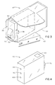
- Fig. 1 shows a perspective view of an automobile having a combination courtesy light and a detachable flashlight assembly mounted in the front passenger side door.
- Fig. 2 is cross-sectional view taken along the line shown in Fig. 1. The position of the courtesy light/flashlight assembly 10 within the door is shown more clearly.
- Fig. 3 illustrates a detailed view of the assembly 10 shown in Figs. 1 and 2.
- the assembly 10 includes a receptacle 20 which forms a compartment extending within the door panel of the vehicle and light unit 30.
- the receptacle 20 is designed to fit the contour of the door panel as seen in Figs. 1 and 2, and can be bolted securely to the inside of the door panel by means of a mounting bracket 40.
- the light unit 30 is shown inserted within receptacle 20, and a detent latch 50 secures the light unit in position.
- a recessed switch 60 is provided for turning the light unit 30 on or off. Switch 60 is recessed so that it does not interfere with the insertion of light unit 30 in receptacle 20.
- Lens 70 may be a single color lens or, as shown, may be a dual colored lens for directing two colored beams of light in opposing directions. This feature is especially useful in the door mounted embodiment of Fig. 1 because a red beam of light can be directed rearwardly from the vehicle to warn oncoming traffic of the open door, while a white beam of light can be directed downward to illuminate the ground to assist the operator in exiting the vehicle.
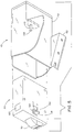
- Fig. 4 depicts the light unit 30 removed form receptacle 20.
- Three metal contacts 80, 90 and 100 are visible at the rear of the light unit 30.
- Fig. 5 depicts light unit 30 and the manner of insertion within receptacle 20.
- the contacts 80, 90 and 100 of Fig. 4 are each designed to form an electrical coupling with a corresponding spring mounted contact 105 protruding from the rear of receptacle 20.
- Each spring mounted contact 105 creates an opposing force on the light unit 30 when it is inserted within receptacle 20. The opposing force insures that the electrical coupling between corresponding contacts is stable and properly conductive.
- a detent latch 50 is provided for locking the light unit 30 against the rim of receptacle 20.
- the detent latch 50 includes a flexible finger extending at an angle from the housing of light unit 30.
- Flexible finger 54 is gradually depressed as the light unit 30 is slid into receptacle 20.
- flexible finger 54 moves past the rim of receptacle 20 and springs outward to lock detent latch 50 against the rim of receptacle 20.
- a tab 58 is provided to allow manual depression of the flexible finger so light unit 30 can be removed from receptacle 20.
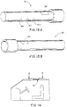
- Figs. 6 and 7 show a top view and a side view, respectively, from which the proportions of the detent latch 50 are clearly visible.
- Fig. 8 depicts the internal components and wiring of the light unit 30 according to one embodiment of the present invention.
- a pair of rechargeable power cells are connected in series to form a battery 130.
- the positive and negative terminals of the battery 130 are connected to contacts 80 and 90, respectively.
- the negative terminal of the batteries are also connected through switch 60 to one terminal of a light source 120.
- the positive terminals of the batteries are connected to the other terminal of light source 120. If the battery 130 is charged by an electrical current applied at contacts 80 and 90, when switch 60 is closed the light source 120 will be powered from the stored charge. Additional benefits can be realized by including batteries 130 within a separate section or light unit 30 which can be detached in order to provide a portable battery unit to power other electrical devices.
- Fig. 9 depicts an alternate embodiment in which switch 60 is mounted on the front of light unit 30 for convenience.
- Fig. 10 depicts a power supply designed to provide 3.3V regulated DC power to spring mounted contacts 100 for powering the light unit 30 or recharging battery 130 when light unit 30 is inserted within receptacle 20.
- the power supply 140 may be located in a separate compartment within receptacle 20.
- Power supply 140 includes a 12V DC input terminal 150 and a ground input terminal 160. Both inputs 150 and 160 can be wired directly to the vehicle electrical system for regulating 12V DC power.
- a resistor 170 is connected to input terminal 150, and a zener diode 180 is connected from resistor 170 to ground terminal 160. Zener diode 180 is also connected through diode 190 to a current amplifier comprising operational amplifier 230 and resistors 200, 210 and 20.
- 12V DC power from the vehicle electrical system is clamped at a predetermined level by diode 180.
- Resistors 200 through 220 and operational amplifier 230 amplify the current to provide a regulated 3.3V DC 35 MA output.
- Three output terminals 240 through 260 are provided. Output terminal 240 is connected directly to the ground input 160. Output terminal 260 is connected directly to the 12V DC unregulated input terminal 150. Output terminal 250 provides the 3.3V regulated DC output signal.
- Fig. 11 depicts the connections of power supply 140 to light unit 30.
- Power supply output terminals 240 and 250 are each connected to a spring 110 and spring mounted contact 105 for providing an electrical coupling to contacts 80 and 90 of light unit 30.
- Power supply output terminal 260 may be connected through an additional spring 110 and spring mounted contact 105 to a spare input terminal (not shown) on the light unit 30.
- the spare input terminal may be configured to provide a conductive path to ground so that when light unit 30 is removed from receptacle 20 the conductive path is broken.
- An indicator light may be provided on the vehicle dashboard for signalling the operator when the conductive path to ground so that when light unit 30 is removed form receptacle 20 the conductive path is broken.
- An indicator light may be provided on the vehicle dashboard for signalling the operator when the conductive path has been broken and the light unit 30 removed.
- the spare input terminal may be configured as a second switch which, upon opening the vehicle door, operates to illuminate the lamp 120.
- Figs. 12A and 12B illustrate another embodiment of the present invention which incorporates a prism 270 for directing light in two directions.
- Prism 270 can then be placed along the path of light emitted from light unit 30. The light beam is split and the resulting two light beams can be directed in the desired directions.
- colored lenses 280 and 290 may be provided along the light paths. This way, a red beam of light can be directed rearwardly from the door to warn oncoming vehicles of the open door, and a white beam of light can be directed downward towards the ground to assist the operator in exiting the vehicle.
- Figs. 13A and 13B depict an alternate embodiment of the invention in which light unit 30 is shown with a different housing which allows more convenient operation as a hand held flashlight.
- Fig. 14 depicts another embodiment of the present invention in which the combination courtesy light/flashlight assembly is housed in the roof of a vehicle.
- Fig. 15 depicts a cross-sectional view of the assembly of Fig. 14 and illustrates the mounting assembly in detail.
- Prism 270 is used to direct the light beam downward into the passenger compartment of the vehicle.
- Fig. 16 illustrates how light unit 30 is detached vertically from receptacle 20 to provide easy access for the vehicle operator.
- Fig. 17 illustrates another embodiment of the present invention in which interlocking rib 280 and groove 290 perform the function of the detent latch 50 of Figs. 6 and 7.
- Rib 280 encircles the periphery of light unit 30, and groove 290 encircles the inner surface of receptacle 20.
- the rib 280 interlocks with groove 290 to provide a secure compression fit.
- Fig. 18 is a perspective view of the present invention as it is typically used.
Abstract
A oombination courtesy light and detachable flashlight assembly (10) includes a light unit (30) which can be detached from a flush-mounted receptacle (20) installed within the panelling of a vehicle. The light unit (30) operates from rechargeable batteries (130) charged by a power supply (140) when the light unit (30) is inserted in the receptacle (20).
Description
- The invention relates to a vehicle light unit and, more particularly, to a vehicle courtesy light which can be detached and used as a flashlight.
- Conventional vehicles often provide a number of courtesy lights for the convenience of the operator. For instance, automobiles are equipped with a passenger compartment light, left and right side door lights, dashboard lights and an engine compartment light, etc. These lights are marginally effective in many situations because of their fixed position. For this reason many operators carry a flashlight for working on the engine, changing tires or searching in obscure places such as under the seat. However, flashlights are inconvenient because they take up additional space in the glove compartment. Moreover, flashlight batteries are often found to be dead in those situations when the operator needs the flashlight most. Attempts have been made to overcome the problem of dead batteries by using electrical cords that can be plugged into the cigarette lighter. This allows the flashlight to operate directly from the car's electrical system, or it may be equipped with a rechargeable battery which recharges from the car's electrical system. In either case, the cord restricts the flashlights freedom of movement, and the flashlight continues to occupy glove compartment space.
- Another more successful attempt at solving the above-described problems is found in U.S. Patent No. 4,819,134 issued to Rossi. Here is shown a rechargeable flashlight and mounting assembly which allows the flashlight to be mounted in the passenger compartment of an automobile for use as an interior light. A mounting plate is provided which connects to the vehicle electrical system so that the battery can be recharged while the vehicle is in operation. Unfortunately, the concept is not efficiently implemented. The Rossi device is designed to be retrofit and does not conveniently mount within the interior panels of the vehicle. When the light is mounted in the passenger compartment an inconvenient and possibly dangerous protrusion exists. Moreover, the configuration of the battery contacts provides an unstable electrical connection to the mounting bracket, and the contacts themselves are susceptible to breaking off. In addition, the illustrated light bulb and charging circuit are designed to operate from a 12V battery which, if designed to drive the light bulb for any length of time, must be much larger than standard 1.5V batteries.
- It is therefore a primary object of the invention to provide a combination automobile courtesy light and a detachable flashlight assembly which is small in size, and is aesthetically pleasing.
- It is another object to provide a structurally sound mounting assembly which firmly locks the flashlight in place and has sturdy electrical contacts which create a secure electrical connection.
- It is a further object of the present invention to provide various mountings so that the light may be used in numerous places within the vehicle.
- According to the present invention these and other objects are accomplished by providing a combination courtesy light and flashlight assembly having a power supply, a compartment within a wall of a vehicle, number of electrical contacts disposed within said compartment and connected to the power supply, and a light unit with a corresponding number of electrical contacts disposed exteriorly for providing a conductive coupling when the light unit is inserted in the compartment. The light unit includes a housing, a rechargeable battery connected to the contacts for storing a charge, a switch mounted on the housing, and a light source controlled by the switch. The stored charge energizes the light source when the switch is closed and the light unit is not inserted in the compartment, and the power supply energizes the light source when the switch is closed and the light unit is inserted in the compartment.
- Other objects, features and advantages of the present invention will become more apparent from the following detailed description of preferred embodiments and certain modifications thereof when taken together with the accompanying drawings, in which:
- Fig. 1 is a perspective view of one embodiment according to the present invention.
- Fig. 2 is a perspective view of the embodiment shown in Fig. 1.
- Fig. 3 depicts the combination courtesy light and detachable flashlight assembly of Fig. 1.
- Fig. 4 illustrates a rear view of the light unit shown in Fig. 3.
- Fig. 5 is a perspective view of the light unit shown in Fig. 3 as it is inserted into the compartment of Fig.3.
- Fig. 6 is a top view of the light unit of Fig. 3.
- Fig. 7 is a side view of the light unit of Fig. 3.
- Fig. 8 is a cutaway view showing the internal circuitry of the light unit of Figs. 6 and 7.
- Fig. 9 is a front view of the light unit of Figs. 6 and 7.
- Fig. 10 is a schematic diagram of the power supply according to one embodiment of the present invention.
- Fig. 11 is a schematic diagram of the internal circuitry of the light unit according to the present invention.
- Fig. 12A and 12B are cutaway views of another embodiment according to the present invention.
- Fig. 13A and 13B are close-up views of the light unit of Fig. 12.
- Fig. 14 is a perspective view of another embodiment according to the present invention which is mounted in the sealing of a passenger car.
- Fig. 15 is a close-up cutaway view of the embodiment of Fig. 14.
- Fig. 16 illustrates the manner of detaching the light unit from the compartment of the invention shown in Fig. 14.
- Fig. 17 depicts another embodiment of the present invention in which an interlocking hinge is substituted for the detent latch of Figs. 6 and 7.
- Fig. 18 is a perspective view illustrating the use of the present invention.
- Referring now to Figs. 1-3, Fig. 1 shows a perspective view of an automobile having a combination courtesy light and a detachable flashlight assembly mounted in the front passenger side door.
- Fig. 2 is cross-sectional view taken along the line shown in Fig. 1. The position of the courtesy light/
flashlight assembly 10 within the door is shown more clearly. - Fig. 3 illustrates a detailed view of the
assembly 10 shown in Figs. 1 and 2. Theassembly 10 includes areceptacle 20 which forms a compartment extending within the door panel of the vehicle andlight unit 30. Thereceptacle 20 is designed to fit the contour of the door panel as seen in Figs. 1 and 2, and can be bolted securely to the inside of the door panel by means of amounting bracket 40. Thelight unit 30 is shown inserted withinreceptacle 20, and adetent latch 50 secures the light unit in position. Arecessed switch 60 is provided for turning thelight unit 30 on or off.Switch 60 is recessed so that it does not interfere with the insertion oflight unit 30 inreceptacle 20. When the light unit is turned on by means ofswitch 60, light emanates from a light source (not shown) and is directed bylens 70.Lens 70 may be a single color lens or, as shown, may be a dual colored lens for directing two colored beams of light in opposing directions. This feature is especially useful in the door mounted embodiment of Fig. 1 because a red beam of light can be directed rearwardly from the vehicle to warn oncoming traffic of the open door, while a white beam of light can be directed downward to illuminate the ground to assist the operator in exiting the vehicle. - Fig. 4 depicts the
light unit 30 removedform receptacle 20. Threemetal contacts light unit 30. - Fig. 5 depicts
light unit 30 and the manner of insertion withinreceptacle 20. Thecontacts contact 105 protruding from the rear ofreceptacle 20. Each spring mountedcontact 105 creates an opposing force on thelight unit 30 when it is inserted withinreceptacle 20. The opposing force insures that the electrical coupling between corresponding contacts is stable and properly conductive. In order to retain thelight unit 30 withinreceptacle 20 against the opposing force created bycontacts 105, adetent latch 50 is provided for locking thelight unit 30 against the rim ofreceptacle 20. Thedetent latch 50 includes a flexible finger extending at an angle from the housing oflight unit 30.Flexible finger 54 is gradually depressed as thelight unit 30 is slid intoreceptacle 20. When thelight unit 30 is fully inserted,flexible finger 54 moves past the rim ofreceptacle 20 and springs outward to lockdetent latch 50 against the rim ofreceptacle 20. Atab 58 is provided to allow manual depression of the flexible finger solight unit 30 can be removed fromreceptacle 20. - Figs. 6 and 7 show a top view and a side view, respectively, from which the proportions of the
detent latch 50 are clearly visible. - Fig. 8 depicts the internal components and wiring of the
light unit 30 according to one embodiment of the present invention. A pair of rechargeable power cells are connected in series to form abattery 130. The positive and negative terminals of thebattery 130 are connected tocontacts switch 60 to one terminal of alight source 120. The positive terminals of the batteries are connected to the other terminal oflight source 120. If thebattery 130 is charged by an electrical current applied atcontacts switch 60 is closed thelight source 120 will be powered from the stored charge. Additional benefits can be realized by includingbatteries 130 within a separate section orlight unit 30 which can be detached in order to provide a portable battery unit to power other electrical devices. - Fig. 9 depicts an alternate embodiment in which switch 60 is mounted on the front of
light unit 30 for convenience. - Fig. 10 depicts a power supply designed to provide 3.3V regulated DC power to spring mounted
contacts 100 for powering thelight unit 30 or rechargingbattery 130 whenlight unit 30 is inserted withinreceptacle 20. Thepower supply 140 may be located in a separate compartment withinreceptacle 20.Power supply 140 includes a 12VDC input terminal 150 and aground input terminal 160. Bothinputs resistor 170 is connected to input terminal 150, and azener diode 180 is connected fromresistor 170 toground terminal 160.Zener diode 180 is also connected throughdiode 190 to a current amplifier comprisingoperational amplifier 230 andresistors diode 180.Resistors 200 through 220 andoperational amplifier 230 amplify the current to provide a regulated 3.3V DC 35 MA output. Threeoutput terminals 240 through 260 are provided.Output terminal 240 is connected directly to theground input 160.Output terminal 260 is connected directly to the 12V DCunregulated input terminal 150.Output terminal 250 provides the 3.3V regulated DC output signal. - Fig. 11 depicts the connections of
power supply 140 tolight unit 30. Powersupply output terminals spring 110 and spring mountedcontact 105 for providing an electrical coupling tocontacts light unit 30. Powersupply output terminal 260 may be connected through anadditional spring 110 and spring mountedcontact 105 to a spare input terminal (not shown) on thelight unit 30. The spare input terminal may be configured to provide a conductive path to ground so that whenlight unit 30 is removed fromreceptacle 20 the conductive path is broken. An indicator light may be provided on the vehicle dashboard for signalling the operator when the conductive path to ground so that whenlight unit 30 is removedform receptacle 20 the conductive path is broken. An indicator light may be provided on the vehicle dashboard for signalling the operator when the conductive path has been broken and thelight unit 30 removed. Alternately, the spare input terminal may be configured as a second switch which, upon opening the vehicle door, operates to illuminate thelamp 120. - Figs. 12A and 12B illustrate another embodiment of the present invention which incorporates a
prism 270 for directing light in two directions. This allows more flexibility in mounting thelight unit 30 within the door panel of the vehicle.Prism 270 can then be placed along the path of light emitted fromlight unit 30. The light beam is split and the resulting two light beams can be directed in the desired directions. In addition,colored lenses - Figs. 13A and 13B depict an alternate embodiment of the invention in which
light unit 30 is shown with a different housing which allows more convenient operation as a hand held flashlight. - Fig. 14 depicts another embodiment of the present invention in which the combination courtesy light/flashlight assembly is housed in the roof of a vehicle.
- Fig. 15 depicts a cross-sectional view of the assembly of Fig. 14 and illustrates the mounting assembly in detail.
Prism 270 is used to direct the light beam downward into the passenger compartment of the vehicle. - Fig. 16 illustrates how
light unit 30 is detached vertically fromreceptacle 20 to provide easy access for the vehicle operator. - Fig. 17 illustrates another embodiment of the present invention in which interlocking
rib 280 and groove 290 perform the function of thedetent latch 50 of Figs. 6 and 7.Rib 280 encircles the periphery oflight unit 30, and groove 290 encircles the inner surface ofreceptacle 20. When thelight unit 30 is inserted within thereceptacle 20, therib 280 interlocks withgroove 290 to provide a secure compression fit. - Fig. 18 is a perspective view of the present invention as it is typically used.
- Having now fully set forth the preferred embodiments and certain modifications of the concept underlying the present invention, various other embodiments as well as certain variations and modifications of the embodiment herein shown and described will obviously occur to those skilled in the art upon becoming familiar with said underlying concept. It is to be understood, therefore, that within the scope of the appended claims, the invention may be practiced otherwise than as specifically set forth herein.
Claims (16)
- A combination flashlight and courtesy light unit for a vehicle, comprising:
power supply means for providing an electric current;
a compartment within a wall of a vehicle;
a first plurality of electrical contacts disposed within said compartment and connected to said power supply;
a light unit adapted for insertion within said compartment, said light unit further comprising,
a housing,
a second plurality of electrical contacts disposed exteriorly on said housing for providing a conductive coupling with said first plurality of contacts when said light unit is inserted in said compartment,
a rechargeable battery connected to said second plurality of contacts for receiving said electrical current and storing a charge when said light unit is inserted in said compartment,
a switch mounted on said housing, and
a light source connected to said battery and to said second plurality of contacts through said switch, said light source being selectively energized by said switch; and
whereby said battery energizes said light source using stored charge when said switch is closed and said light unit is not inserted in said compartment, and said power supply means energizes said light source when said switch is closed and said light unit is inserted in said compartment. - The combination courtesy light and flashlight assembly according to claim 1, wherein said power supply is connected to a 12V vehicle electrical system for providing less than 12V regulated DC power to said battery.
- The combination courtesy light and flashlight assembly according to claim 2, wherein said power supply means is connected to a 12V vehicle electrical system for providing 3.3V or less regulated DC power to said battery.
- The combination courtesy light and flashlight assembly according to claim 2, wherein said power supply means further comprises a 12V unregulated DC input, a ground input, a resistor connected to said 12V input, a first diode having a cathode connected to said resistor and an anode connected to said ground input, a second diode having an anode connected to the cathode of said first diode ad having a cathode, and a current amplifier connected between the cathode of said second diode and said ground input.
- The combination courtesy light and flashlight assembly according to claim 2, wherein said current amplifier further comprises an operational amplifier and three resistors.
- The combination courtesy light and flashlight assembly according to claim 1, further comprising a prism arranged adjacent to said light unit for directing light in a predetermined direction.
- The combination courtesy light and flashlight assembly according to claim 1, wherein said first plurality of electrical contacts are spring-mounted for providing an opposing force when said light unit is inserted into said compartment.
- The combination courtesy light and flashlight assembly according to claim 7, wherein said first plurality of electrical contacts comprises three electrical contacts.
- The combination courtesy light and flashlight assembly according to claim 1, wherein said light unit further comprises locking means disposed on said housing for retaining the light unit within said compartment against the opposing force of said first plurality of contacts.
- The combination courtesy light and flashlight assembly according to claim 9, wherein said locking means comprises a rib disposed around the periphery of said housing, and said compartment is defined by an internal peripheral groove for receiving said rib.
- The combination courtesy light and flashlight assembly according to claim 9, wherein said locking means comprises a detent latch, said detent latch defined by a flexible finger for engaging a rim of said compartment when said light unit is inserted in said compartment, and a protruding catch for allowing manual depression of said flexible finger for removal of said light unit.
- The combination courtesy light and flashlight assembly according to claim 1, wherein said compartment is mounted within the roof of a vehicle for providing a detachable overhead light.
- The combination courtesy light and flashlight assembly according to claim 12, wherein said light unit further comprises a lens covering said light source for directing light generated thereby.
- The combination courtesy light and flashlight assembly according to claim 1, wherein said receptacle is mounted in the door of a vehicle.
- The combination courtesy light and flashlight assembly according to claim 14, wherein said light unit further comprises a lens covering maid light source for directing light generated thereby.
- The combination courtesy light and flashlight assembly according to claim 15, wherein said lens is a dual color lens.
Applications Claiming Priority (2)
| Application Number | Priority Date | Filing Date | Title |
|---|---|---|---|
| US564787 | 1983-12-20 | ||
| US07/564,787 US5077643A (en) | 1990-08-09 | 1990-08-09 | Combination courtesy light and detachable flashlight assembly |
Publications (1)
| Publication Number | Publication Date |
|---|---|
| EP0475922A1 true EP0475922A1 (en) | 1992-03-18 |
Family
ID=24255891
Family Applications (1)
| Application Number | Title | Priority Date | Filing Date |
|---|---|---|---|
| EP91870121A Withdrawn EP0475922A1 (en) | 1990-08-09 | 1991-08-09 | Combination courtesy light and detachable flashlight assembly |
Country Status (3)
| Country | Link |
|---|---|
| US (1) | US5077643A (en) |
| EP (1) | EP0475922A1 (en) |
| JP (1) | JPH04230439A (en) |
Cited By (3)
| Publication number | Priority date | Publication date | Assignee | Title |
|---|---|---|---|---|
| DE19962561A1 (en) * | 1999-12-23 | 2001-06-21 | Daimler Chrysler Ag | Holder in vehicle for removable torch; has or co-operates with unit, which is assigned in light-emitting surface of torch, to vary its beam direction or beam angle |
| FR2878201A1 (en) * | 2005-05-30 | 2006-05-26 | Faurecia Interieur Ind Snc | Motor vehicle, has pocket lamp inserted in housing at level of upper wall and projecting slightly through opening, where housing has grooves receiving strips of case of lamp during insertion of lamp and is complementary to case |
| DE102012105673B4 (en) | 2011-12-16 | 2020-06-18 | Hyundai Motor Company | Trunk light |
Families Citing this family (46)
| Publication number | Priority date | Publication date | Assignee | Title |
|---|---|---|---|---|
| US5467258A (en) * | 1992-12-21 | 1995-11-14 | The Coleman Company, Inc. | Flashlight apparatus |
| FR2703811B1 (en) * | 1993-04-07 | 1995-07-13 | Ecia Equip Composants Ind Auto | DEVICE FOR MAKING INFORMATION INSIDE THE INSIDE VISIBLE AND ITS APPLICATION TO A MOTOR VEHICLE. |
| US5569997A (en) * | 1993-10-04 | 1996-10-29 | Ford Motor Company | Power supply for volatile memory devices and portable electrical appliance in vehicles |
| US5379201A (en) * | 1994-01-10 | 1995-01-03 | Friedman; Arthur S. | Portable light for laptop computer |
| US5599086A (en) * | 1995-06-06 | 1997-02-04 | Ford Motor Company | Vehicle track lighting system |
| US5645340A (en) * | 1995-06-19 | 1997-07-08 | Colton; Orren L. | Flashlight replacement for vehicle ashtray |
| JP3282127B2 (en) * | 1996-12-26 | 2002-05-13 | 矢崎総業株式会社 | Indoor lighting unit |
| GB2332267A (en) * | 1997-12-09 | 1999-06-16 | Rover Group | Detachable interior vehicle lamp |
| US5969437A (en) * | 1997-12-16 | 1999-10-19 | Kalidon Technology, Inc. | Dual powered, smoke detector activated flashlight |
| US5984495A (en) * | 1998-02-26 | 1999-11-16 | Roberts; Steve | Vehicular dome light with removable flashlight |
| US6428172B1 (en) * | 1999-11-24 | 2002-08-06 | Donnelly Corporation | Rearview mirror assembly with utility functions |
| DE19822636A1 (en) * | 1998-05-21 | 1999-11-25 | Sidler Gmbh & Co | Lighting device on motor vehicle door |
| US6079858A (en) * | 1998-08-17 | 2000-06-27 | Lear Automotive Dearborn, Inc. | Side view mirror with detachable flashlight |
| US6231219B1 (en) | 1999-03-03 | 2001-05-15 | Kurt L. Lohss | Dual-purpose glovebox light assembly and cradle therefor |
| US6273378B1 (en) * | 1999-06-23 | 2001-08-14 | Sam Fu | Vehicle auxiliary-lamp mounting assembly |
| US6338517B1 (en) | 2000-01-20 | 2002-01-15 | Lear Corporation | Overhead console for a vehicle |
| US6398394B1 (en) | 2000-07-21 | 2002-06-04 | Jack K. Winnik | Vehicle dome light and flashlight |
| JP4908673B2 (en) * | 2000-10-05 | 2012-04-04 | 株式会社東海理化電機製作所 | Room mirror |
| US6669260B2 (en) | 2001-05-01 | 2003-12-30 | Johnson Controls Technology Company | Modular system for a vehicle |
| US6921118B2 (en) | 2002-04-22 | 2005-07-26 | Johnson Controls Technology Company | Sliding and nesting console system |
| US7152897B2 (en) * | 2002-04-22 | 2006-12-26 | Johnson Controls Technology Company | Article attachment system |
| US20070035161A1 (en) * | 2002-08-27 | 2007-02-15 | Johnson Controls Technology Company | Overhead system for a vehicle |
| EP1534559A2 (en) * | 2002-08-27 | 2005-06-01 | Johnson Controls Technology Company | Transparent vehicle roof with arrangement for receiving articles |
| US7090371B1 (en) * | 2002-09-17 | 2006-08-15 | George Bonar | Removable headlamp for a vehicle |
| US6701995B1 (en) | 2002-11-26 | 2004-03-09 | Irvin Automotive Products, Inc. | Combination shade handle and security light |
| US6896395B2 (en) * | 2003-08-01 | 2005-05-24 | Lear Corporation | Vehicular retractable interior lighting system |
| US20060087836A1 (en) * | 2004-10-27 | 2006-04-27 | Morris Steven E | Portable lighting assembly for automotive vehicle |
| US7258555B2 (en) * | 2005-03-15 | 2007-08-21 | International Automotive Components Group North America, Inc. | System and method for electrical power track and slidable accessories |
| US7300189B2 (en) * | 2005-06-28 | 2007-11-27 | Federal-Mogul World Wide, Inc. | Interchangeable flashlight-cargo lamp system |
| US20070121316A1 (en) * | 2005-11-28 | 2007-05-31 | Michael Hoermann | Garage door drive with a light unit |
| US20070133219A1 (en) * | 2005-12-13 | 2007-06-14 | Brian Chaloult | Vehicle interior light assembly with removable flashlight |
| CN101089452A (en) * | 2006-06-16 | 2007-12-19 | 阿吉特·库巴尼 | Portable and mountable light bulb and fixture |
| US20080180942A1 (en) * | 2007-01-31 | 2008-07-31 | Hansen David B | Cabinet Lamp |
| US7832911B2 (en) * | 2008-04-28 | 2010-11-16 | James Jesse L | Motorcycle safety device |
| FR2938219B1 (en) * | 2008-11-10 | 2011-08-12 | Peugeot Citroen Automobiles Sa | MOTOR VEHICLE DOOR HAVING A LIGHT SOURCE INTEGRATED WITH AN ENERGY-SAVING LAMP, UNLOCKING HANDLE HOLDER PLATE AND INTERNAL CLOSURE PANEL |
| US8052311B2 (en) * | 2008-11-26 | 2011-11-08 | Ilo Kristo Xhunga | Pull-down self-supportive lighting mounted on hand-reachable ceilings |
| US20110149560A1 (en) * | 2009-12-23 | 2011-06-23 | Ivus Industries, Llc | System and method for interfacing portable hand-held devices |
| US20150049500A1 (en) * | 2013-08-14 | 2015-02-19 | Ford Global Technologies, Llc | Vehicle interior and portable accessory light assembly |
| FR3026815B1 (en) * | 2014-10-01 | 2016-12-30 | Valeo Vision | REMOVABLE ELECTRICAL DEVICE OF A MOTOR VEHICLE |
| US10011221B2 (en) * | 2014-10-14 | 2018-07-03 | Ford Global Technologies, Llc | Lighted visor mirror with a removable lighting module |
| JP6869778B2 (en) * | 2017-03-31 | 2021-05-12 | 株式会社村上開明堂 | Courtesy lamp and courtesy logo lamp |
| US10753553B2 (en) | 2017-06-29 | 2020-08-25 | Black & Decker Inc. | Cordless underhood light with detachable work light |
| US10759330B1 (en) | 2019-05-14 | 2020-09-01 | Ford Global Technologies, Llc | Tie-down bracket for motor vehicle |
| US10875461B2 (en) | 2019-05-29 | 2020-12-29 | Ford Global Technologies, Llc | Tie-down bracket for motor vehicle |
| US10994662B2 (en) | 2019-05-31 | 2021-05-04 | Ford Global Technologies, Llc | Tie-down bracket for motor vehicle |
| US20230034903A1 (en) * | 2021-07-28 | 2023-02-02 | Rivian Ip Holdings, Llc | In-door accessory charger |
Citations (5)
| Publication number | Priority date | Publication date | Assignee | Title |
|---|---|---|---|---|
| WO1987003354A1 (en) * | 1985-11-26 | 1987-06-04 | Martin Lonsdale Lee | Lighting device |
| DE3624367A1 (en) * | 1986-07-18 | 1988-01-28 | Witte & Sutor Gmbh | Chargeable hand or pocket lamp and/or on-board lamp for operations on the electrical motor vehicle system with integrated system voltage monitoring and charging control |
| DE3727346A1 (en) * | 1987-08-17 | 1989-03-02 | Happich Gmbh Gebr | Illuminating device for vehicles |
| US4819139A (en) * | 1988-01-04 | 1989-04-04 | Thomas Jack L | Rechargeable flashlight assembly for automotive vehicles |
| US4819134A (en) * | 1987-09-25 | 1989-04-04 | Rossi Marc A | Interior automobile light |
Family Cites Families (9)
| Publication number | Priority date | Publication date | Assignee | Title |
|---|---|---|---|---|
| US3096941A (en) * | 1960-01-20 | 1963-07-09 | Gen Motors Corp | Rechargeable flashlight assembly |
| US3825740A (en) * | 1972-09-22 | 1974-07-23 | A Friedman | Rechargeable flashlight and support stand therefor |
| GB1517379A (en) * | 1975-10-31 | 1978-07-12 | Kent Ltd G | Electrical circuit means powered by a rechargeable batter |
| US4168411A (en) * | 1977-08-08 | 1979-09-18 | Trw Inc. | Closure switch for a compartment |
| AU527442B2 (en) * | 1977-11-08 | 1983-03-03 | Duff King And Noel Trevor Bowman Christopher | Battery charger |
| US4398139A (en) * | 1978-11-30 | 1983-08-09 | Prinsze Onno M | Rechargeable flashlight combined with a constant current battery charging circuit |
| US4282562A (en) * | 1979-10-29 | 1981-08-04 | James Marino | Combination rechargeable flashlight and charger base |
| US4388673A (en) * | 1981-06-22 | 1983-06-14 | Mag Instrument, Inc. | Variable light beam flashlight and recharging unit |
| DE3712530A1 (en) * | 1987-04-13 | 1988-11-03 | Fischer Artur Werke Gmbh | STORAGE CONTAINER WITH DRAWER ELEMENT |
-
1990
- 1990-08-09 US US07/564,787 patent/US5077643A/en not_active Expired - Lifetime
-
1991
- 1991-04-24 JP JP3187125A patent/JPH04230439A/en active Pending
- 1991-08-09 EP EP91870121A patent/EP0475922A1/en not_active Withdrawn
Patent Citations (5)
| Publication number | Priority date | Publication date | Assignee | Title |
|---|---|---|---|---|
| WO1987003354A1 (en) * | 1985-11-26 | 1987-06-04 | Martin Lonsdale Lee | Lighting device |
| DE3624367A1 (en) * | 1986-07-18 | 1988-01-28 | Witte & Sutor Gmbh | Chargeable hand or pocket lamp and/or on-board lamp for operations on the electrical motor vehicle system with integrated system voltage monitoring and charging control |
| DE3727346A1 (en) * | 1987-08-17 | 1989-03-02 | Happich Gmbh Gebr | Illuminating device for vehicles |
| US4819134A (en) * | 1987-09-25 | 1989-04-04 | Rossi Marc A | Interior automobile light |
| US4819139A (en) * | 1988-01-04 | 1989-04-04 | Thomas Jack L | Rechargeable flashlight assembly for automotive vehicles |
Cited By (3)
| Publication number | Priority date | Publication date | Assignee | Title |
|---|---|---|---|---|
| DE19962561A1 (en) * | 1999-12-23 | 2001-06-21 | Daimler Chrysler Ag | Holder in vehicle for removable torch; has or co-operates with unit, which is assigned in light-emitting surface of torch, to vary its beam direction or beam angle |
| FR2878201A1 (en) * | 2005-05-30 | 2006-05-26 | Faurecia Interieur Ind Snc | Motor vehicle, has pocket lamp inserted in housing at level of upper wall and projecting slightly through opening, where housing has grooves receiving strips of case of lamp during insertion of lamp and is complementary to case |
| DE102012105673B4 (en) | 2011-12-16 | 2020-06-18 | Hyundai Motor Company | Trunk light |
Also Published As
| Publication number | Publication date |
|---|---|
| JPH04230439A (en) | 1992-08-19 |
| US5077643A (en) | 1991-12-31 |
Similar Documents
| Publication | Publication Date | Title |
|---|---|---|
| US5077643A (en) | Combination courtesy light and detachable flashlight assembly | |
| KR20080022586A (en) | Interchangeable flashlight-cargo lamp system | |
| US8393766B2 (en) | Lighted exterior mirror assembly for vehicle | |
| JP3003456U (en) | Car radio receiver | |
| KR20180126759A (en) | Charging apparatus for vehicle | |
| US5800040A (en) | Internal rearview mirror with courtesy lights | |
| JP2924553B2 (en) | Charging connector for electric vehicles | |
| US4819134A (en) | Interior automobile light | |
| US20050219854A1 (en) | Illuminated grab handle assembly wih integrated control features | |
| WO2006067460A1 (en) | Removable lighting system for a vehicle luggage compartment | |
| US20080180238A1 (en) | Vehicle signaling device having a remote power source | |
| US20080122608A1 (en) | Removable vehicle signaling device | |
| US20060087836A1 (en) | Portable lighting assembly for automotive vehicle | |
| US7104674B2 (en) | Interior illumination lamp | |
| ES2016755A6 (en) | Removable mirror device mounted inside motor vehicles. | |
| US5590949A (en) | Detachable front panel for car stereos | |
| CN218929318U (en) | Vehicle lamp for vehicle and vehicle with same | |
| GB2332185A (en) | A motor vehicle sun visor with a detachable light unit | |
| KR101589876B1 (en) | Flashlight-Loom lamp for vehicle | |
| KR0122579Y1 (en) | Trunk lamp of a car | |
| CN212796677U (en) | Vehicle body assembly and vehicle with same | |
| KR20210063863A (en) | Detachable vehicle interior light | |
| WO2022123881A1 (en) | Vehicle | |
| WO2005118338A1 (en) | The flank indicator lamp and a rear guard lamp | |
| US20080122590A1 (en) | Vehicle signaling device |
Legal Events
| Date | Code | Title | Description |
|---|---|---|---|
| PUAI | Public reference made under article 153(3) epc to a published international application that has entered the european phase |
Free format text: ORIGINAL CODE: 0009012 |
|
| AK | Designated contracting states |
Kind code of ref document: A1 Designated state(s): AT BE CH DE DK ES FR GB GR IT LI LU NL SE |
|
| 17P | Request for examination filed |
Effective date: 19920918 |
|
| 17Q | First examination report despatched |
Effective date: 19931202 |
|
| STAA | Information on the status of an ep patent application or granted ep patent |
Free format text: STATUS: THE APPLICATION IS DEEMED TO BE WITHDRAWN |
|
| 18D | Application deemed to be withdrawn |
Effective date: 19950110 |