EP0475882A1 - Hollow metal article fabrication - Google Patents
Hollow metal article fabrication Download PDFInfo
- Publication number
- EP0475882A1 EP0475882A1 EP91630065A EP91630065A EP0475882A1 EP 0475882 A1 EP0475882 A1 EP 0475882A1 EP 91630065 A EP91630065 A EP 91630065A EP 91630065 A EP91630065 A EP 91630065A EP 0475882 A1 EP0475882 A1 EP 0475882A1
- Authority
- EP
- European Patent Office
- Prior art keywords
- article
- preform
- segments
- die
- bonding
- Prior art date
- Legal status (The legal status is an assumption and is not a legal conclusion. Google has not performed a legal analysis and makes no representation as to the accuracy of the status listed.)
- Granted
Links
Images


Classifications
-
- B—PERFORMING OPERATIONS; TRANSPORTING
- B23—MACHINE TOOLS; METAL-WORKING NOT OTHERWISE PROVIDED FOR
- B23P—METAL-WORKING NOT OTHERWISE PROVIDED FOR; COMBINED OPERATIONS; UNIVERSAL MACHINE TOOLS
- B23P15/00—Making specific metal objects by operations not covered by a single other subclass or a group in this subclass
- B23P15/04—Making specific metal objects by operations not covered by a single other subclass or a group in this subclass turbine or like blades from several pieces
-
- F—MECHANICAL ENGINEERING; LIGHTING; HEATING; WEAPONS; BLASTING
- F01—MACHINES OR ENGINES IN GENERAL; ENGINE PLANTS IN GENERAL; STEAM ENGINES
- F01D—NON-POSITIVE DISPLACEMENT MACHINES OR ENGINES, e.g. STEAM TURBINES
- F01D5/00—Blades; Blade-carrying members; Heating, heat-insulating, cooling or antivibration means on the blades or the members
- F01D5/12—Blades
- F01D5/14—Form or construction
- F01D5/147—Construction, i.e. structural features, e.g. of weight-saving hollow blades
-
- F—MECHANICAL ENGINEERING; LIGHTING; HEATING; WEAPONS; BLASTING
- F01—MACHINES OR ENGINES IN GENERAL; ENGINE PLANTS IN GENERAL; STEAM ENGINES
- F01D—NON-POSITIVE DISPLACEMENT MACHINES OR ENGINES, e.g. STEAM TURBINES
- F01D5/00—Blades; Blade-carrying members; Heating, heat-insulating, cooling or antivibration means on the blades or the members
- F01D5/12—Blades
- F01D5/14—Form or construction
- F01D5/18—Hollow blades, i.e. blades with cooling or heating channels or cavities; Heating, heat-insulating or cooling means on blades
-
- B—PERFORMING OPERATIONS; TRANSPORTING
- B21—MECHANICAL METAL-WORKING WITHOUT ESSENTIALLY REMOVING MATERIAL; PUNCHING METAL
- B21D—WORKING OR PROCESSING OF SHEET METAL OR METAL TUBES, RODS OR PROFILES WITHOUT ESSENTIALLY REMOVING MATERIAL; PUNCHING METAL
- B21D26/00—Shaping without cutting otherwise than using rigid devices or tools or yieldable or resilient pads, i.e. applying fluid pressure or magnetic forces
- B21D26/02—Shaping without cutting otherwise than using rigid devices or tools or yieldable or resilient pads, i.e. applying fluid pressure or magnetic forces by applying fluid pressure
- B21D26/053—Shaping without cutting otherwise than using rigid devices or tools or yieldable or resilient pads, i.e. applying fluid pressure or magnetic forces by applying fluid pressure characterised by the material of the blanks
- B21D26/059—Layered blanks
-
- B—PERFORMING OPERATIONS; TRANSPORTING
- B21—MECHANICAL METAL-WORKING WITHOUT ESSENTIALLY REMOVING MATERIAL; PUNCHING METAL
- B21D—WORKING OR PROCESSING OF SHEET METAL OR METAL TUBES, RODS OR PROFILES WITHOUT ESSENTIALLY REMOVING MATERIAL; PUNCHING METAL
- B21D53/00—Making other particular articles
- B21D53/78—Making other particular articles propeller blades; turbine blades
-
- Y—GENERAL TAGGING OF NEW TECHNOLOGICAL DEVELOPMENTS; GENERAL TAGGING OF CROSS-SECTIONAL TECHNOLOGIES SPANNING OVER SEVERAL SECTIONS OF THE IPC; TECHNICAL SUBJECTS COVERED BY FORMER USPC CROSS-REFERENCE ART COLLECTIONS [XRACs] AND DIGESTS
- Y02—TECHNOLOGIES OR APPLICATIONS FOR MITIGATION OR ADAPTATION AGAINST CLIMATE CHANGE
- Y02T—CLIMATE CHANGE MITIGATION TECHNOLOGIES RELATED TO TRANSPORTATION
- Y02T50/00—Aeronautics or air transport
- Y02T50/60—Efficient propulsion technologies, e.g. for aircraft
-
- Y—GENERAL TAGGING OF NEW TECHNOLOGICAL DEVELOPMENTS; GENERAL TAGGING OF CROSS-SECTIONAL TECHNOLOGIES SPANNING OVER SEVERAL SECTIONS OF THE IPC; TECHNICAL SUBJECTS COVERED BY FORMER USPC CROSS-REFERENCE ART COLLECTIONS [XRACs] AND DIGESTS
- Y10—TECHNICAL SUBJECTS COVERED BY FORMER USPC
- Y10T—TECHNICAL SUBJECTS COVERED BY FORMER US CLASSIFICATION
- Y10T29/00—Metal working
- Y10T29/49—Method of mechanical manufacture
- Y10T29/49316—Impeller making
- Y10T29/49336—Blade making
- Y10T29/49339—Hollow blade
Definitions
- the present invention relates to the fabrication of hollow metal structures, and more particularly to an improved method for making hollow airfoil type structures utilizing one side machining of preforms, forging, diffusion bonding, and superplastic inflation forming techniques.
- Gas turbine engines have been extensively developed and find particular utility in aircraft propulsion. As performance and efficiency requirements become increasingly stringent, weight reduction becomes exceptionally important. Accordingly, many gas turbine engine components are desirably fabricated with hollow interiors.
- the invention process separates the article to be fabricated into two or more segments along a plane which defines surfaces along which the segments will be bonded.
- a finite element analysis is performed to simulate the manufacturing operations in reverse, i.e., go from the finished article geometry to the required starting segment geometry.
- the finite element analysis determination of preform geometry includes the general steps of starting with a segment of the finished article, constructing a grid throughout the segment, and applying the stresses involved in the inverse of the manufacturing operations to simulate the movement (or strain) of the metal for each grid point. This procedure defines the preform configuration required to produce the segment of the finished article.
- the finite element analysis calculations are commonly performed using well-known established computer programs.
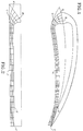
- Figure 1 shows a typical airfoil cross-section which has been divided into two segments.
- a finite element analysis grid has been constructed in one segment.
- the dashed lines show extra material, required for the fabrication process, which is removed in a finishing operation.
- Figure 2 shows the preform configuration determined by finite element analysis. Comparison of grid points A,B,C,D,E and F of Figure 1 with the corresponding grid points A′,B′,C′,D′,E′ and F′ of Figure 2 indicate how the finite element analysis has predicted the metal will flow during the fabrication operations.
- the outer surface of the object can be transformed by the finite element analysis calculations to a flat surface in the preform.
- the preform can be made from rectangular material with machining performed on only one side of the rectangular starting material. This is shown by the dashed lines of Figure 2.
- each preform segment The bond surfaces and the recessed area of each preform segment are machined such that when the two segments are aligned and bonded, a hollow intermediate article with an internal cavity is formed. Although it will usually be the case that mating cavities are machined in the preforms, it is possible that, for some designs, machining of only one side of only one preform would be feasible. Since the finished article has curved outer surfaces it is essential that some deformation (forging) of the material occurs in the bond regions before or during the bonding operation. This deformation is also essential for producing good bond joints.
- Figure 1 is a cross-sectional view of a segment of a finished object, with a finite element grid superimposed on one segment.
- Figure 2 is a cross-sectional view of a preform configuration after finite element analysis has been performed on the segment shown in Figure 1.
- Figure 3 is a perspective view of a hollow airfoil to be fabricated.
- Figure 4 is a perspective view of two preform segments as machined.
- Figure 5 is a perspective view of the two preform segments aligned in preparation for forging and bonding.
- Figure 6 is a cross-sectional view at Section 6-6 of Figure 5.
- Figure 7 is a perspective view of the mating halves of the die used to forge and bond the preform.
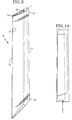
- Figure 8 is a perspective view of the airfoil preform after forging, bonding, and superplastic inflating.
- Figure 9 is a cross-sectional view at Section 9-9 of Figure 8.
- Figure 10 shows the outline of the finished hollow airfoil overlaid on the preform of Figure 8.
- the finished airfoil 10 is defined by a leading edge 12, a trailing edge 14, airfoil surfaces 16, a tip region 18, and a root region 20.
- a hollow portion 22 extends the full length of the airfoil.
- the airfoil is separated into two segments along the neutral stress plane 24.
- the neutral stress plane 24 is that plane within the airfoil in which the operating stresses change from tensile to compressive, and is thus the location of minimum stress. Thus, after bonding along the neutral stress plane, any potential weakness in the bond joint occurs where the operating stresses are at a minimum.
- Finite element analysis is performed to reverse the sequence of manufacturing operations used to form the airfoil segments.
- the finite element calculation models the material movement during forging as it is affected by temperature, pressure, and strain rate.
- the outer surfaces of the airfoils are translated to flat surfaces, with built up areas appropriately located to generate the airfoil structure. Extra material is added all around the outline of the preform segments for handling purposes, and a minimum form (usually rectangular) which completely encompasses the preform segments is generated.
- the starting material In order to successfully produce components by this method, the starting material must be superplastic at the bonding and forming conditions to be used; i.e., it must be capable of being plastically deformed large amounts without incurring localized thinning during deformation. This generally occurs at elevated temperatures, low strain rates, and relatively low loads, and is often dependent on material properties, such as grain size and texture.
- materials including alpha-beta titanium alloys, some steels and some nickel-based superalloys inherently have, or can be processed to have, superplastic properties.
- all machining of the preform segments 25 is performed on one side of the rectangular starting material.
- all of the surfaces are machined flat, although some surfaces 26 are at an angle to the reference plane 27, which is one of the original surfaces of the rectangular starting material.
- Mating grooves 28 are machined into the preform segments 25 to receive an inflation tube.
- Machined cavities 29 are located in the preform segments so as to provide the cavity in the hollow article.
- the two preform segments 25 are positioned appropriately for the bonding operation.
- a anti-bonding material such as yttrium oxide, is usually applied to the surfaces where bonding is not desired, in this case, the recessed areas 29 of the preform segments 25 which form the cavity in the hollow article.
- Tackwelds 30 are used to hold the segments in position relative to each other, although various other methods, including tabs, pins, etc., could be satisfactorily used.
- Figure 6 is a cross-section at Section 6-6 of Figure 5 showing the relationship of the segments ready for forging and bonding.
- FIG. 7 the two halves of a forging die 31, 32 having cavities 34, 36 machined to conform to the outer surface contours required in the finished airfoil, are shown. Proper alignment of the die halves during processing operations is assured by four posts 38 which fit into four holes 40. Mating grooves 42 are machined into the two die halves such that they will align with the grooves 28 in the airfoil segments and receive the inflation tube 44.
- TZM molybdenum has the advantage that it is more resistant to creep, and thus retains its shape longer than the other materials over a long production run.
- TZM molybdenum is exceedingly susceptible to oxidation at temperatures greater than about 800°F, and, consequently, its use requires that elevated temperature operations be performed under non-oxidizing atmosphere or high vacuum conditions. This would also assure good bonding conditions for materials such as titanium alloys, which are highly susceptible to oxidation.
- the assembled components shown in Figure 5 are placed in the forging die, and an inflation tube 44 is inserted through the mating grooves 42 in the die into the hole formed by the mating grooves 26 in the assembled preform.
- the material for the inflation tube 44 is selected to withstand the bonding pressure without collapsing and to have a thermal expansion coefficient greater than that of the airfoil material. Thus, the tube will expand to form a tight seal when heated to the inflation temperature, and then will contract during cooling to facilitate removal of the tube from the completed preform.
- the forging die with assembled components in position is placed in a forging press capable of applying the required force to the surfaces of the die.
- the die and assembled preform components are raised to the forging/bonding temperature.
- the forging pressure is applied to the die, the two halves of the die move toward each other, and the superplastic material of the two preform segments is forged to conform to the die cavity, with the material in the bond areas providing support for forging.
- the appropriate curvature is formed on the leading and trailing edges where rectangular cross-sections were present in the preform segments.
- Stop blocks 46 are sized and positioned to limit the travel of the die while permitting a minimum of 8% deformation in all regions where the bond surfaces are in contact.
- the airfoil preform is machined to the outline shown in Figure 10, and additional machining or hand finishing is done as necessary to finish the leading and trailing edge contours. This is necessary only in those limited areas where additional material was added to facilitate fabrication and thus, the final airfoil contours were not fully defined by the mold cavity. Additional components are added to provide, for example, mounting or pivot features to complete the part.
- a hollow airfoil was fabricated from Ti-6Al-4V alloy according to Figures 2 through 10. After machining to the configuration of Figure 4, yttrium oxide was applied to the cavities in the preform segments as an anti-bonding material, and the preform segments were tack welded together.
- TZM molybdemum was selected as the die material because of its greater resistance to creep than steel or nickel-base superalloys.
- the forging and bonding operations were conducted concurrently.
- the article was then completed by cutting the preform to the outline of the airfoil, and shaping the leading and trailing edges to remove the extra material added for handling purposes.
Landscapes
- Engineering & Computer Science (AREA)
- Mechanical Engineering (AREA)
- General Engineering & Computer Science (AREA)
- Architecture (AREA)
- Forging (AREA)
- Pressure Welding/Diffusion-Bonding (AREA)
Abstract
Description
- The present invention relates to the fabrication of hollow metal structures, and more particularly to an improved method for making hollow airfoil type structures utilizing one side machining of preforms, forging, diffusion bonding, and superplastic inflation forming techniques.
- Gas turbine engines have been extensively developed and find particular utility in aircraft propulsion. As performance and efficiency requirements become increasingly stringent, weight reduction becomes exceptionally important. Accordingly, many gas turbine engine components are desirably fabricated with hollow interiors.
- Many techniques have been developed for the fabrication of these hollow components. Typical operations include machining, forging, casting, and bonding. These operations, among others, are found in various combinations in, for example, U.S. patent Nos. 3,623,204; 3,628,226; 4,089,456; 4,364,160; and 4,642,863, which are incorporated herein by reference.
- These fabrication processes all involve complex machining operations (invariably on all sides of preforms), a multiplicity of components, numerous operations, and/or complex tooling. All of these factors increase fabrication time and cost.
- Accordingly, it is an object of the present invention to fabricate hollow airfoils using simplified machining concepts and simple bond tooling while assuring that the finished article will have the required configuration.
- This and other objects and advantages of the present invention will be made clear through reference to the following description of the preferred embodiments, figures, and claims.
- The invention process separates the article to be fabricated into two or more segments along a plane which defines surfaces along which the segments will be bonded. In order to provide a starting segment configuration, a finite element analysis is performed to simulate the manufacturing operations in reverse, i.e., go from the finished article geometry to the required starting segment geometry.
- The finite element analysis determination of preform geometry includes the general steps of starting with a segment of the finished article, constructing a grid throughout the segment, and applying the stresses involved in the inverse of the manufacturing operations to simulate the movement (or strain) of the metal for each grid point. This procedure defines the preform configuration required to produce the segment of the finished article. The finite element analysis calculations are commonly performed using well-known established computer programs.
- Figure 1 shows a typical airfoil cross-section which has been divided into two segments. A finite element analysis grid has been constructed in one segment. The dashed lines show extra material, required for the fabrication process, which is removed in a finishing operation. Figure 2 shows the preform configuration determined by finite element analysis. Comparison of grid points A,B,C,D,E and F of Figure 1 with the corresponding grid points A′,B′,C′,D′,E′ and F′ of Figure 2 indicate how the finite element analysis has predicted the metal will flow during the fabrication operations.
- One of the features of this invention is that the outer surface of the object can be transformed by the finite element analysis calculations to a flat surface in the preform. Thus, the preform can be made from rectangular material with machining performed on only one side of the rectangular starting material. This is shown by the dashed lines of Figure 2.
- The bond surfaces and the recessed area of each preform segment are machined such that when the two segments are aligned and bonded, a hollow intermediate article with an internal cavity is formed. Although it will usually be the case that mating cavities are machined in the preforms, it is possible that, for some designs, machining of only one side of only one preform would be feasible. Since the finished article has curved outer surfaces it is essential that some deformation (forging) of the material occurs in the bond regions before or during the bonding operation. This deformation is also essential for producing good bond joints.
- There is no internal support for the thin regions which define the cavity during the forging and bonding operations. Thus, elevated pressure is applied internal to the hollow article while at elevated temperature. This operation, called superplastic inflation, assures that the bonded preform assumes the configuration of a cavity machined into the die used for the inflation operation.
- After these fabrication operations have been completed, excess material is trimmed from the edges of the preform to finish the article.
- The foregoing and other features and advantages of the present invention will become more apparent from the following description and accompanying drawings.
- Figure 1 is a cross-sectional view of a segment of a finished object, with a finite element grid superimposed on one segment.
- Figure 2 is a cross-sectional view of a preform configuration after finite element analysis has been performed on the segment shown in Figure 1.
- Figure 3 is a perspective view of a hollow airfoil to be fabricated.
- Figure 4 is a perspective view of two preform segments as machined.
- Figure 5 is a perspective view of the two preform segments aligned in preparation for forging and bonding.
- Figure 6 is a cross-sectional view at Section 6-6 of Figure 5.
- Figure 7 is a perspective view of the mating halves of the die used to forge and bond the preform.
- Figure 8 is a perspective view of the airfoil preform after forging, bonding, and superplastic inflating.
- Figure 9 is a cross-sectional view at Section 9-9 of Figure 8.
- Figure 10 shows the outline of the finished hollow airfoil overlaid on the preform of Figure 8.
- The invention process is best understood through consideration of Figures 1 through 10 which illustrate the fabrication sequence for formation of a hollow airfoil.
- Referring first to Figure 3, the finished
airfoil 10 is defined by a leadingedge 12, atrailing edge 14,airfoil surfaces 16, atip region 18, and aroot region 20. Ahollow portion 22 extends the full length of the airfoil. - The airfoil is separated into two segments along the
neutral stress plane 24. Theneutral stress plane 24 is that plane within the airfoil in which the operating stresses change from tensile to compressive, and is thus the location of minimum stress. Thus, after bonding along the neutral stress plane, any potential weakness in the bond joint occurs where the operating stresses are at a minimum. - Finite element analysis, previously discussed in regard to Figures 1 and 2, is performed to reverse the sequence of manufacturing operations used to form the airfoil segments. The finite element calculation models the material movement during forging as it is affected by temperature, pressure, and strain rate. In the present invention, the outer surfaces of the airfoils are translated to flat surfaces, with built up areas appropriately located to generate the airfoil structure. Extra material is added all around the outline of the preform segments for handling purposes, and a minimum form (usually rectangular) which completely encompasses the preform segments is generated.
- In order to successfully produce components by this method, the starting material must be superplastic at the bonding and forming conditions to be used; i.e., it must be capable of being plastically deformed large amounts without incurring localized thinning during deformation. This generally occurs at elevated temperatures, low strain rates, and relatively low loads, and is often dependent on material properties, such as grain size and texture. Several materials including alpha-beta titanium alloys, some steels and some nickel-based superalloys inherently have, or can be processed to have, superplastic properties.
- Referring to Figure 4, all machining of the
preform segments 25 is performed on one side of the rectangular starting material. For this particular configuration, all of the surfaces are machined flat, although somesurfaces 26 are at an angle to thereference plane 27, which is one of the original surfaces of the rectangular starting material.Mating grooves 28 are machined into thepreform segments 25 to receive an inflation tube.Machined cavities 29 are located in the preform segments so as to provide the cavity in the hollow article. - Referring to Figure 5, the two
preform segments 25 are positioned appropriately for the bonding operation. A anti-bonding material, such as yttrium oxide, is usually applied to the surfaces where bonding is not desired, in this case, the recessedareas 29 of thepreform segments 25 which form the cavity in the hollow article.Tackwelds 30 are used to hold the segments in position relative to each other, although various other methods, including tabs, pins, etc., could be satisfactorily used. - Figure 6 is a cross-section at Section 6-6 of Figure 5 showing the relationship of the segments ready for forging and bonding.
- Referring to Figure 7, the two halves of a forging
die 31, 32 havingcavities posts 38 which fit into fourholes 40.Mating grooves 42 are machined into the two die halves such that they will align with thegrooves 28 in the airfoil segments and receive theinflation tube 44. - Although the materials commonly used for these applications exhibit superplasticity and high ductility at elevated temperatures, relatively high forces are required for forging. Practical die materials available for these forging, bonding and inflation operations include superalloys, some steels, and molybdenum based materials, such as TZM molybdenum. TZM molybdenum has the advantage that it is more resistant to creep, and thus retains its shape longer than the other materials over a long production run. However, TZM molybdenum is exceedingly susceptible to oxidation at temperatures greater than about 800°F, and, consequently, its use requires that elevated temperature operations be performed under non-oxidizing atmosphere or high vacuum conditions. This would also assure good bonding conditions for materials such as titanium alloys, which are highly susceptible to oxidation.
- The assembled components shown in Figure 5 are placed in the forging die, and an
inflation tube 44 is inserted through themating grooves 42 in the die into the hole formed by themating grooves 26 in the assembled preform. The material for theinflation tube 44 is selected to withstand the bonding pressure without collapsing and to have a thermal expansion coefficient greater than that of the airfoil material. Thus, the tube will expand to form a tight seal when heated to the inflation temperature, and then will contract during cooling to facilitate removal of the tube from the completed preform. - The forging die with assembled components in position is placed in a forging press capable of applying the required force to the surfaces of the die. The die and assembled preform components are raised to the forging/bonding temperature. When the forging pressure is applied to the die, the two halves of the die move toward each other, and the superplastic material of the two preform segments is forged to conform to the die cavity, with the material in the bond areas providing support for forging. By this means, the appropriate curvature is formed on the leading and trailing edges where rectangular cross-sections were present in the preform segments. Stop blocks 46 are sized and positioned to limit the travel of the die while permitting a minimum of 8% deformation in all regions where the bond surfaces are in contact.
- When the die segments have moved to the limit of their motion, the forging pressure is maintained for a period of time sufficient to permit diffusion bonding at the contacting surfaces of the preform segments. At the end of this bonding period, a pressurized non-oxidizing inflation gas is introduced through the inflation tube into the preform cavity. The inflation pressure is sufficient to force the thin regions which define the cavity of the hollow article outward against the die cavity inner surfaces, thus establishing the final configuration of the airfoil surfaces. Additionally, if slight waves are present in the thin regions, the superplastic nature of the material allows their removal without buckling as the finished airfoil configuration is established. Figure 8 shows the completed airfoil preform, while Figure 9 shows a cross-section at Section 9-9 of Figure 8.
- The airfoil preform is machined to the outline shown in Figure 10, and additional machining or hand finishing is done as necessary to finish the leading and trailing edge contours. This is necessary only in those limited areas where additional material was added to facilitate fabrication and thus, the final airfoil contours were not fully defined by the mold cavity. Additional components are added to provide, for example, mounting or pivot features to complete the part.
- As an example of the present invention, a hollow airfoil was fabricated from Ti-6Al-4V alloy according to Figures 2 through 10. After machining to the configuration of Figure 4, yttrium oxide was applied to the cavities in the preform segments as an anti-bonding material, and the preform segments were tack welded together.
- TZM molybdemum was selected as the die material because of its greater resistance to creep than steel or nickel-base superalloys.
- The forging and bonding operations were conducted concurrently. A temperature of 1700°F and a pressure of 2000 psi, based on the contact area of the bond surfaces, were used, with the conditions being maintained for a period of 60 minutes to provide the optimum bond strength.
- While the forged and bonded preform was still in the forging press, the superplastic inflation operation was performed. Argon gas was introduced through the inflation tube at a pressure of 200 psi, and held at 1700°F for a period of 15 minutes, which assured that the airfoil contours matched the die cavity.
- The article was then completed by cutting the preform to the outline of the airfoil, and shaping the leading and trailing edges to remove the extra material added for handling purposes.
- While this example has depicted the forging, bonding and inflation steps as connected operations in the same equipment, they could also be performed as discrete operations.
- Although this invention has been shown and described with respect to detailed embodiments thereof, it will be understood by those skilled in the art that various changes in form and detail thereof may be made without departing from the spirit and scope of the claimed invention.
Claims (9)
- A method for fabricating a hollow metal article including the steps of:a. machining one side only of at least one of at least two mating preform segments to a predetermined preform configuration which includes at least one recessed area in said segments;b. forging and bonding said preform segments in a forging die so that the outer surfaces of said preform segments essentially conform with the inner surfaces of a cavity in said forging die and the non-recessed areas of the preform segment are bonded together, thus forming a bonded article containing at least one internal cavity;c. inflating said bonded article by forcing high pressure non-oxidizing gas into said at least one internal cavity in said bonded article such that said outer surfaces of said bonded article conform to the inner surfaces of a cavity in an inflation die; andd. machining said article to a desired final configuration.
- A method as in claim 1 wherein said hollow article is a gas turbine engine airfoil.
- A method as in claim 1 wherein said mating segments have a configuration determined by a finite element analysis technique which reverses the sequence of manufacturing operations used to produce said article such that said outer surfaces are translated to a flat plane on which is built up material necessary to produce solid portions of said article, thus permitting all machining operations to be performed on one side of said preform segments.
- A method as in claim 1 wherein bonding occurs along the neutral stress plane of said finished article.
- A method as in claim 1 wherein the steps of forging, bonding and inflation are performed as a single series of operations in the same tooling.
- A method as in claim 1 wherein the tube which provides high pressure gas to inflate said hollow article inside said die has a coefficient of thermal expansion greater than that of the material of said hollow article.
- A method as in claim 1 wherein said material used to fabricate said hollow article has superplastic properties at the fabrication temperature.
- A method as in claim 1 wherein the areas of said preform segments which define a cavity are coated with an anti-bonding material.
- A method as in claim 1 wherein each of two of said preform segments includes a recessed area.
Applications Claiming Priority (2)
| Application Number | Priority Date | Filing Date | Title |
|---|---|---|---|
| US07/583,262 US5083371A (en) | 1990-09-14 | 1990-09-14 | Hollow metal article fabrication |
| US583262 | 1990-09-14 |
Publications (2)
| Publication Number | Publication Date |
|---|---|
| EP0475882A1 true EP0475882A1 (en) | 1992-03-18 |
| EP0475882B1 EP0475882B1 (en) | 1995-03-29 |
Family
ID=24332376
Family Applications (1)
| Application Number | Title | Priority Date | Filing Date |
|---|---|---|---|
| EP91630065A Expired - Lifetime EP0475882B1 (en) | 1990-09-14 | 1991-09-05 | Hollow metal article fabrication |
Country Status (4)
| Country | Link |
|---|---|
| US (1) | US5083371A (en) |
| EP (1) | EP0475882B1 (en) |
| JP (1) | JP2918722B2 (en) |
| DE (1) | DE69108493T2 (en) |
Cited By (3)
| Publication number | Priority date | Publication date | Assignee | Title |
|---|---|---|---|---|
| EP1081333A2 (en) * | 1999-08-31 | 2001-03-07 | General Electric Company | Plastically formed hybrid airfoil |
| CN101786223B (en) * | 2010-02-12 | 2012-11-07 | 中国航空工业集团公司北京航空制造工程研究所 | Manufacturing method of titanium alloy hollow component |
| EP3798117A1 (en) * | 2019-09-26 | 2021-03-31 | The Boeing Company | Reinforced superplastic formed and diffusion bonded structures |
Families Citing this family (42)
| Publication number | Priority date | Publication date | Assignee | Title |
|---|---|---|---|---|
| DE4041104C1 (en) * | 1990-12-21 | 1992-06-04 | Mtu Muenchen Gmbh | |
| US5240376A (en) * | 1991-07-31 | 1993-08-31 | Mcdonnell Douglas Corporation | SPF/DB hollow core fan blade |
| US5246340A (en) * | 1991-11-19 | 1993-09-21 | Allied-Signal Inc. | Internally cooled airfoil |
| US5457884A (en) * | 1992-08-14 | 1995-10-17 | Rolls-Royce Plc | Method of manufacturing an article by superplastic forming and diffusion bonding |
| GB2269555B (en) * | 1992-08-14 | 1995-01-04 | Rolls Royce Plc | A method of manufacturing an article by superplastic forming and diffusion bonding |
| US5269058A (en) * | 1992-12-16 | 1993-12-14 | General Electric Company | Design and processing method for manufacturing hollow airfoils |
| GB9306175D0 (en) * | 1993-03-25 | 1993-05-19 | British Aerospace | Method of bonding and superplastic forming |
| US5469618A (en) * | 1993-12-06 | 1995-11-28 | General Electric Company | Method for manufacturing hollow airfoils (two-piece concept) |
| US5448829A (en) * | 1994-01-31 | 1995-09-12 | United Technologies Corporation | Hollow titanium blade manufacturing |
| DE4416147C2 (en) * | 1994-05-09 | 1998-04-09 | Schaefer Hydroforming Gmbh | Application of the hydroforming process for producing a curved metallic longitudinal hollow body and a hydroforming press that can be used for this purpose |
| US5581882A (en) * | 1994-06-07 | 1996-12-10 | Rolls-Royce Plc | Method of manufacturing an article by superplastic forming and diffusion bonding |
| FR2724127B1 (en) * | 1994-09-07 | 1996-12-20 | Snecma | PROCESS FOR MANUFACTURING A HOLLOW BLADE OF A TURBOMACHINE |
| US5503532A (en) * | 1994-11-14 | 1996-04-02 | General Electric Company | Diffusion bonded airfoil and method |
| FR2739045B1 (en) * | 1995-09-27 | 1997-10-31 | Snecma | PROCESS FOR MANUFACTURING A HOLLOW BLADE OF A TURBOMACHINE |
| FR2749784B1 (en) * | 1996-06-13 | 1998-07-31 | Snecma | PROCESS FOR MANUFACTURING A HOLLOW BLADE OF TURBOMACHINE AND MULTI-EFFECT PRESS OVEN USED FOR THEIR IMPLEMENTATION |
| FR2752539B1 (en) * | 1996-08-22 | 1998-09-18 | Snecma | PROCESS FOR MANUFACTURING A HOLLOW BLADE OF A TURBOMACHINE AND HOT-SCALABLE TURNING EQUIPMENT |
| US5890285A (en) * | 1996-08-23 | 1999-04-06 | Mcdonnell Douglas Corporation | Method for superplastically forming a structural article |
| FR2754478B1 (en) * | 1996-10-16 | 1998-11-20 | Snecma | PROCESS FOR MANUFACTURING A HOLLOW BLADE OF A TURBOMACHINE |
| JP3935278B2 (en) * | 1998-11-12 | 2007-06-20 | 株式会社東芝 | Method for manufacturing a blade of a fluid machine |
| GB0203955D0 (en) * | 2002-02-20 | 2002-04-03 | Rolls Royce Plc | A method of manufacturing an article by diffusion bonding and super[lastic forming |
| US6705011B1 (en) | 2003-02-10 | 2004-03-16 | United Technologies Corporation | Turbine element manufacture |
| US7080971B2 (en) * | 2003-03-12 | 2006-07-25 | Florida Turbine Technologies, Inc. | Cooled turbine spar shell blade construction |
| FR2867992B1 (en) * | 2004-03-29 | 2007-06-29 | Snecma Moteurs Sa | FORGING MATRIX WITH MEANS OF REPERAGE |
| US7380321B2 (en) * | 2006-03-28 | 2008-06-03 | The Boeing Company | Machining technique with selective and localized placement of tooling material |
| US7798388B2 (en) * | 2007-05-31 | 2010-09-21 | Applied Materials, Inc. | Method of diffusion bonding a fluid flow apparatus |
| US7931443B1 (en) * | 2007-07-10 | 2011-04-26 | Florida Turbine Technologies, Inc. | High twist composite blade |
| US8652276B2 (en) * | 2009-12-22 | 2014-02-18 | Sprint AeroSystems, Inc. | System and method for forming contoured new and near-net shape titanium parts |
| US8956700B2 (en) | 2011-10-19 | 2015-02-17 | General Electric Company | Method for adhering a coating to a substrate structure |
| CA2893299C (en) | 2014-06-02 | 2017-11-14 | Rolls-Royce Corporation | Fixture for high temperature joining |
| US10150158B2 (en) | 2015-12-17 | 2018-12-11 | General Electric Company | Method and assembly for forming components having internal passages using a jacketed core |
| US10099283B2 (en) | 2015-12-17 | 2018-10-16 | General Electric Company | Method and assembly for forming components having an internal passage defined therein |
| US9579714B1 (en) | 2015-12-17 | 2017-02-28 | General Electric Company | Method and assembly for forming components having internal passages using a lattice structure |
| US10137499B2 (en) | 2015-12-17 | 2018-11-27 | General Electric Company | Method and assembly for forming components having an internal passage defined therein |
| US10099284B2 (en) | 2015-12-17 | 2018-10-16 | General Electric Company | Method and assembly for forming components having a catalyzed internal passage defined therein |
| US9968991B2 (en) | 2015-12-17 | 2018-05-15 | General Electric Company | Method and assembly for forming components having internal passages using a lattice structure |
| US10118217B2 (en) | 2015-12-17 | 2018-11-06 | General Electric Company | Method and assembly for forming components having internal passages using a jacketed core |
| US10099276B2 (en) | 2015-12-17 | 2018-10-16 | General Electric Company | Method and assembly for forming components having an internal passage defined therein |
| US9987677B2 (en) | 2015-12-17 | 2018-06-05 | General Electric Company | Method and assembly for forming components having internal passages using a jacketed core |
| US10046389B2 (en) | 2015-12-17 | 2018-08-14 | General Electric Company | Method and assembly for forming components having internal passages using a jacketed core |
| US10335853B2 (en) | 2016-04-27 | 2019-07-02 | General Electric Company | Method and assembly for forming components using a jacketed core |
| US10286450B2 (en) | 2016-04-27 | 2019-05-14 | General Electric Company | Method and assembly for forming components using a jacketed core |
| GB201609988D0 (en) * | 2016-06-08 | 2016-07-20 | Rolls Royce Plc | Datum positioning in dies |
Citations (3)
| Publication number | Priority date | Publication date | Assignee | Title |
|---|---|---|---|---|
| US4098476A (en) * | 1977-06-07 | 1978-07-04 | The United States Of America As Represented By The Secretary Of The Army | Mechanical support |
| US4301584A (en) * | 1980-01-31 | 1981-11-24 | United Technologies Corporation | Method of forming fiber and metal matrix composite |
| DE3211777A1 (en) * | 1981-04-01 | 1982-10-14 | Rolls-Royce Ltd., London | METHOD FOR PRODUCING A TURBINE BLADE |
Family Cites Families (12)
| Publication number | Priority date | Publication date | Assignee | Title |
|---|---|---|---|---|
| US3628226A (en) * | 1970-03-16 | 1971-12-21 | Aerojet General Co | Method of making hollow compressor blades |
| US3736638A (en) * | 1971-04-07 | 1973-06-05 | United Aircraft Corp | Method for bonding opposed parts of a hollow article together |
| US4043498A (en) * | 1974-02-11 | 1977-08-23 | Tre Corporation | Method of plastic flow diffusion bonding |
| US4089456A (en) * | 1977-06-28 | 1978-05-16 | United Technologies Corporation | Controlled-pressure diffusion bonding and fixture therefor |
| US4364160A (en) * | 1980-11-03 | 1982-12-21 | General Electric Company | Method of fabricating a hollow article |
| US4811890A (en) * | 1983-05-07 | 1989-03-14 | Rockwell International Corporation | Method of eliminating core distortion in diffusion bonded and uperplastically formed structures |
| US4642863A (en) * | 1985-04-15 | 1987-02-17 | Ontario Technologies Corporation | Manufacturing method for hollow metal airfoil type structure |
| US4768700A (en) * | 1987-08-17 | 1988-09-06 | General Motors Corporation | Diffusion bonding method |
| US4882823A (en) * | 1988-01-27 | 1989-11-28 | Ontario Technologies Corp. | Superplastic forming diffusion bonding process |
| US4916928A (en) * | 1988-04-28 | 1990-04-17 | Mcdonnell Douglas Corporation | Stops for curved SPF/DB sandwich fabrication |
| US4833768A (en) * | 1988-04-28 | 1989-05-30 | Mcdonnell Douglas Corporation | Curved SPF/DB sandwich fabrication |
| US4934580A (en) * | 1988-12-27 | 1990-06-19 | Barnes Group, Inc. | Method of making superplastically formed and diffusion bonded articles and the articles so made |
-
1990
- 1990-09-14 US US07/583,262 patent/US5083371A/en not_active Expired - Lifetime
-
1991
- 1991-09-05 DE DE69108493T patent/DE69108493T2/en not_active Expired - Lifetime
- 1991-09-05 EP EP91630065A patent/EP0475882B1/en not_active Expired - Lifetime
- 1991-09-17 JP JP3265263A patent/JP2918722B2/en not_active Expired - Fee Related
Patent Citations (3)
| Publication number | Priority date | Publication date | Assignee | Title |
|---|---|---|---|---|
| US4098476A (en) * | 1977-06-07 | 1978-07-04 | The United States Of America As Represented By The Secretary Of The Army | Mechanical support |
| US4301584A (en) * | 1980-01-31 | 1981-11-24 | United Technologies Corporation | Method of forming fiber and metal matrix composite |
| DE3211777A1 (en) * | 1981-04-01 | 1982-10-14 | Rolls-Royce Ltd., London | METHOD FOR PRODUCING A TURBINE BLADE |
Non-Patent Citations (1)
| Title |
|---|
| VDI-Z ENTWICKLUNG, KONSTRUK- TION, PRODUKTION, vol. 129, no. 3, March 1987, VDI-Ver- lag, DÙsseldorf HERBERTZ, NEUMANN "Modernes Gesenkschmieden" pages 109-116 * |
Cited By (5)
| Publication number | Priority date | Publication date | Assignee | Title |
|---|---|---|---|---|
| EP1081333A2 (en) * | 1999-08-31 | 2001-03-07 | General Electric Company | Plastically formed hybrid airfoil |
| EP1081333A3 (en) * | 1999-08-31 | 2004-01-02 | General Electric Company | Plastically formed hybrid airfoil |
| CN101786223B (en) * | 2010-02-12 | 2012-11-07 | 中国航空工业集团公司北京航空制造工程研究所 | Manufacturing method of titanium alloy hollow component |
| EP3798117A1 (en) * | 2019-09-26 | 2021-03-31 | The Boeing Company | Reinforced superplastic formed and diffusion bonded structures |
| US11260952B2 (en) | 2019-09-26 | 2022-03-01 | The Boeing Company | Reinforced superplastic formed and diffusion bonded structures |
Also Published As
| Publication number | Publication date |
|---|---|
| US5083371A (en) | 1992-01-28 |
| JPH04253532A (en) | 1992-09-09 |
| EP0475882B1 (en) | 1995-03-29 |
| JP2918722B2 (en) | 1999-07-12 |
| DE69108493T2 (en) | 1995-07-27 |
| DE69108493D1 (en) | 1995-05-04 |
Similar Documents
| Publication | Publication Date | Title |
|---|---|---|
| US5083371A (en) | Hollow metal article fabrication | |
| US5269058A (en) | Design and processing method for manufacturing hollow airfoils | |
| US5469618A (en) | Method for manufacturing hollow airfoils (two-piece concept) | |
| US5636440A (en) | Process for manufacturing a hollow blade for a turbo-machine | |
| US4815939A (en) | Twisted hollow airfoil with non-twisted internal support ribs | |
| US5099573A (en) | Method of making hollow articles | |
| US5243758A (en) | Design and processing method for manufacturing hollow airfoils (three-piece concept) | |
| JP5424523B2 (en) | Method for manufacturing a reinforced leading or trailing edge for a fan blade | |
| US5826332A (en) | Method and manufacturing a hollow turbomachine blade | |
| US5343619A (en) | Hollow blade for a turbomachine and method of manufacturing said blade | |
| US4071183A (en) | Fabrication method and fabricated article | |
| US4043498A (en) | Method of plastic flow diffusion bonding | |
| US4934580A (en) | Method of making superplastically formed and diffusion bonded articles and the articles so made | |
| US6467168B2 (en) | Method of manufacturing an article by diffusion bonding and superplastic forming | |
| CA2009649A1 (en) | Dual-alloy disk system | |
| US5323536A (en) | Method of manufacturing an article by superplastic forming and diffusion bonding | |
| US5072871A (en) | Method of making hollow articles | |
| US3588980A (en) | Method for making a contoured article | |
| US4197978A (en) | Method of making an integral structural member | |
| US20200222967A1 (en) | Methods for producing creep age formed aircraft components | |
| WO1994023890A1 (en) | Hot forming process | |
| US5139887A (en) | Superplastically formed cellular article | |
| US5285573A (en) | Method for manufacturing hollow airfoils (four-piece concept) | |
| US2799919A (en) | Sheet metal blade and manufacture | |
| EP0431019B1 (en) | Dual-alloy disk system |
Legal Events
| Date | Code | Title | Description |
|---|---|---|---|
| PUAI | Public reference made under article 153(3) epc to a published international application that has entered the european phase |
Free format text: ORIGINAL CODE: 0009012 |
|
| AK | Designated contracting states |
Kind code of ref document: A1 Designated state(s): DE FR GB |
|
| 17P | Request for examination filed |
Effective date: 19920907 |
|
| 17Q | First examination report despatched |
Effective date: 19931025 |
|
| GRAA | (expected) grant |
Free format text: ORIGINAL CODE: 0009210 |
|
| AK | Designated contracting states |
Kind code of ref document: B1 Designated state(s): DE FR GB |
|
| ET | Fr: translation filed | ||
| REF | Corresponds to: |
Ref document number: 69108493 Country of ref document: DE Date of ref document: 19950504 |
|
| PLBE | No opposition filed within time limit |
Free format text: ORIGINAL CODE: 0009261 |
|
| STAA | Information on the status of an ep patent application or granted ep patent |
Free format text: STATUS: NO OPPOSITION FILED WITHIN TIME LIMIT |
|
| 26N | No opposition filed | ||
| REG | Reference to a national code |
Ref country code: GB Ref legal event code: IF02 |
|
| PGFP | Annual fee paid to national office [announced via postgrant information from national office to epo] |
Ref country code: FR Payment date: 20070904 Year of fee payment: 17 |
|
| REG | Reference to a national code |
Ref country code: FR Ref legal event code: ST Effective date: 20090529 |
|
| PG25 | Lapsed in a contracting state [announced via postgrant information from national office to epo] |
Ref country code: FR Free format text: LAPSE BECAUSE OF NON-PAYMENT OF DUE FEES Effective date: 20080930 |
|
| PGFP | Annual fee paid to national office [announced via postgrant information from national office to epo] |
Ref country code: GB Payment date: 20100901 Year of fee payment: 20 |
|
| PGFP | Annual fee paid to national office [announced via postgrant information from national office to epo] |
Ref country code: DE Payment date: 20100901 Year of fee payment: 20 |
|
| REG | Reference to a national code |
Ref country code: DE Ref legal event code: R071 Ref document number: 69108493 Country of ref document: DE |
|
| REG | Reference to a national code |
Ref country code: DE Ref legal event code: R071 Ref document number: 69108493 Country of ref document: DE |
|
| REG | Reference to a national code |
Ref country code: GB Ref legal event code: PE20 Expiry date: 20110904 |
|
| PG25 | Lapsed in a contracting state [announced via postgrant information from national office to epo] |
Ref country code: GB Free format text: LAPSE BECAUSE OF EXPIRATION OF PROTECTION Effective date: 20110904 |
|
| PG25 | Lapsed in a contracting state [announced via postgrant information from national office to epo] |
Ref country code: DE Free format text: LAPSE BECAUSE OF EXPIRATION OF PROTECTION Effective date: 20110906 |