EP0473540B1 - Wärmehaushalt bei Feststoffelektrolyt-Brennstoffzellen - Google Patents
Wärmehaushalt bei Feststoffelektrolyt-Brennstoffzellen Download PDFInfo
- Publication number
- EP0473540B1 EP0473540B1 EP91810607A EP91810607A EP0473540B1 EP 0473540 B1 EP0473540 B1 EP 0473540B1 EP 91810607 A EP91810607 A EP 91810607A EP 91810607 A EP91810607 A EP 91810607A EP 0473540 B1 EP0473540 B1 EP 0473540B1
- Authority
- EP
- European Patent Office
- Prior art keywords
- air
- heat
- members
- temperature
- equalising
- Prior art date
- Legal status (The legal status is an assumption and is not a legal conclusion. Google has not performed a legal analysis and makes no representation as to the accuracy of the status listed.)
- Expired - Lifetime
Links
Images


Classifications
-
- H—ELECTRICITY
- H01—ELECTRIC ELEMENTS
- H01M—PROCESSES OR MEANS, e.g. BATTERIES, FOR THE DIRECT CONVERSION OF CHEMICAL ENERGY INTO ELECTRICAL ENERGY
- H01M8/00—Fuel cells; Manufacture thereof
- H01M8/04—Auxiliary arrangements, e.g. for control of pressure or for circulation of fluids
- H01M8/04007—Auxiliary arrangements, e.g. for control of pressure or for circulation of fluids related to heat exchange
- H01M8/04014—Heat exchange using gaseous fluids; Heat exchange by combustion of reactants
-
- H—ELECTRICITY
- H01—ELECTRIC ELEMENTS
- H01M—PROCESSES OR MEANS, e.g. BATTERIES, FOR THE DIRECT CONVERSION OF CHEMICAL ENERGY INTO ELECTRICAL ENERGY
- H01M8/00—Fuel cells; Manufacture thereof
- H01M8/24—Grouping of fuel cells, e.g. stacking of fuel cells
- H01M8/241—Grouping of fuel cells, e.g. stacking of fuel cells with solid or matrix-supported electrolytes
- H01M8/2425—High-temperature cells with solid electrolytes
-
- H—ELECTRICITY
- H01—ELECTRIC ELEMENTS
- H01M—PROCESSES OR MEANS, e.g. BATTERIES, FOR THE DIRECT CONVERSION OF CHEMICAL ENERGY INTO ELECTRICAL ENERGY
- H01M8/00—Fuel cells; Manufacture thereof
- H01M8/24—Grouping of fuel cells, e.g. stacking of fuel cells
- H01M8/2465—Details of groupings of fuel cells
-
- H—ELECTRICITY
- H01—ELECTRIC ELEMENTS
- H01M—PROCESSES OR MEANS, e.g. BATTERIES, FOR THE DIRECT CONVERSION OF CHEMICAL ENERGY INTO ELECTRICAL ENERGY
- H01M8/00—Fuel cells; Manufacture thereof
- H01M8/10—Fuel cells with solid electrolytes
- H01M8/12—Fuel cells with solid electrolytes operating at high temperature, e.g. with stabilised ZrO2 electrolyte
- H01M2008/1293—Fuel cells with solid oxide electrolytes
-
- H—ELECTRICITY
- H01—ELECTRIC ELEMENTS
- H01M—PROCESSES OR MEANS, e.g. BATTERIES, FOR THE DIRECT CONVERSION OF CHEMICAL ENERGY INTO ELECTRICAL ENERGY
- H01M2300/00—Electrolytes
- H01M2300/0017—Non-aqueous electrolytes
- H01M2300/0065—Solid electrolytes
- H01M2300/0068—Solid electrolytes inorganic
- H01M2300/0071—Oxides
- H01M2300/0074—Ion conductive at high temperature
-
- H—ELECTRICITY
- H01—ELECTRIC ELEMENTS
- H01M—PROCESSES OR MEANS, e.g. BATTERIES, FOR THE DIRECT CONVERSION OF CHEMICAL ENERGY INTO ELECTRICAL ENERGY
- H01M8/00—Fuel cells; Manufacture thereof
- H01M8/04—Auxiliary arrangements, e.g. for control of pressure or for circulation of fluids
- H01M8/04007—Auxiliary arrangements, e.g. for control of pressure or for circulation of fluids related to heat exchange
- H01M8/04014—Heat exchange using gaseous fluids; Heat exchange by combustion of reactants
- H01M8/04022—Heating by combustion
-
- Y—GENERAL TAGGING OF NEW TECHNOLOGICAL DEVELOPMENTS; GENERAL TAGGING OF CROSS-SECTIONAL TECHNOLOGIES SPANNING OVER SEVERAL SECTIONS OF THE IPC; TECHNICAL SUBJECTS COVERED BY FORMER USPC CROSS-REFERENCE ART COLLECTIONS [XRACs] AND DIGESTS
- Y02—TECHNOLOGIES OR APPLICATIONS FOR MITIGATION OR ADAPTATION AGAINST CLIMATE CHANGE
- Y02E—REDUCTION OF GREENHOUSE GAS [GHG] EMISSIONS, RELATED TO ENERGY GENERATION, TRANSMISSION OR DISTRIBUTION
- Y02E60/00—Enabling technologies; Technologies with a potential or indirect contribution to GHG emissions mitigation
- Y02E60/30—Hydrogen technology
- Y02E60/50—Fuel cells
Definitions
- the invention relates to a method according to the preamble of claim 1, temperature compensation bodies for carrying out the method and batteries of solid electrolyte fuel cells which have such compensation bodies.
- the fuel gas which is composed primarily of hydrogen and / or carbon monoxide and / or methane, reacts with oxygen ions at the negative electrode (anode), water and / or carbon dioxide being formed and electrons being released.
- the oxygen comes from air, the oxygen molecules of which are dissociated and ionized at the positive electrode (cathode).
- the oxygen ions diffuse through the solid electrolyte, which lies as a thin, gas-tight layer between the two porous, layered electrodes and which is oxide ion-conducting at higher temperatures (above around 1100 K).
- solid electrolyte fuel cells Various types are known (see, for example, Brian Riley “Solid Oxide Fuel Cells - the Next Stage “in Journal of Power Sources, 29 (1990) 223-237).
- the solid electrolyte fuel cell is hereinafter referred to as” fuel cell “or simply” cell “and the fuel gas as” gas ".
- the heat of reaction is absorbed by the oxygen-supplying air and discharged into the exhaust gas.
- the air must be supplied in large excess. It is common to use five times more air than would be required for the reaction. Despite this large excess of air, the difference between the outlet and inlet temperatures is still around 200 K, which leads to difficult design problems due to the thermal stresses occurring in the ceramic solid electrolytes.
- the invention has two major advantages: Since the fuel cells can be operated with a reduced excess of air, the system costs are reduced thanks to smaller recuperators. A two to three times the excess air compared to the previous five times is sufficient. Despite the reduced excess of air, temperature differences occur in the electrochemically active structures due to the temperature compensation heads, which are smaller or at least not significantly larger than 20 K. This results in less critical thermal stresses.
- Claims 2 to 6 relate to procedures as to how the heat balance in the fuel cell battery can advantageously be carried out.
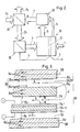
- electrochemically active structures 11 which are flat and extended and which are made up of cathode 11a, solid electrolyte 11b and anode 11c.
- the air (arrows B) is passed through channels 12b in the x direction over the cathode 11a, while the gas (arrows C) is passed through channels 12c in the y direction over the anode 11c.
- the channels 12b and 12c are groove-like grooves on the two sides of the so-called "bipolar separator plate" 12. This separator plate 12 is electrically conductive.
- the fuel cell battery according to Fig.la consists of a stack of separator plates 12, 12 'and electrochemically active structures 11, 11', which are alternately layered in the z-direction and which all have the same rectangular area (area F). On the four sides of the stack parallel to the z direction, distributors and collectors (not shown) for the air or the gas are arranged. At the lower and accordingly on the upper side the stack is closed by an end plate 13. The electrical current generated in the battery flows in the z direction; it is proportional to the area F.
- the battery voltage is proportional to the number of cells, one cell comprising the zone delimited by the two dash-dotted lines 100 and 100 ′.
- the electrochemically active structures 11 are also extended over a large area; however, they are corrugated transversely to one direction (the x direction), which results in parallel air ducts 12b and gas ducts 12c.
- layers 11a 'and 11c' of electrode material - corresponding to the adjacent electrode - are added on both sides, as a result of which the channels 12b and 12c become tubular.
- the method according to the invention also relates to fuel cells with electrochemically active structures that extend over a large area, such as are present in the fuel cells just described. This method is related to the heat balance of the fuel cell, which will be discussed in more detail with reference to FIG. 2:
- the gas 1 and the oxygen in the air 2 are reacted at the electrodes of the electrochemically active structure 11, the chemical energy being converted into electrical energy 3 and heat 4 transforms.
- a very good fuel cell produces approximately the same amount of both types of energy.
- the used gas 5, of which about 15% has not yet been oxidized passes together with the air 6 emerging from the fuel cell, the temperature of which is around 800 degrees Celsius, into an afterburner 50, where exhaust gas 7 is produced at a temperature of, for example, 1000 degrees .
- the hot exhaust gas 7 the fresh air 2a is heated to around 600 degrees in a recuperator, the "external recuperator”20; the partially cooled exhaust gas 7a can be fed to another heating purpose.
- the heated fresh air 2b is heated in the "internal recuperator" 30, to which the temperature compensation bodies according to the invention belong, with the heat of reaction 4 to practically the reaction temperature and is fed to the cathode in this state.
- the fresh air 2b preheated in the external recuperator 20 passes through heat exchanger elements when entering the fuel cell 10, as are described below as an exemplary embodiment in connection with FIG.
- These heat exchanger elements are fed by heat from the temperature compensation bodies, whereby they further heat the air 2b to about 700 degrees.
- the air 2b then comes into contact with the compensating bodies, which further increases their temperature.
- the heat flow conditions that occur are explained with reference to FIG. 3.
- the fuel cell 40 with the temperature compensation body 31 shown in detail in FIG. 3 could be implemented, for example, in a fuel cell battery according to FIG.
- the compensating body 31 consists of two parallel plates 31a and 31c, the plate 31c and the corresponding plate 31c 'of the adjacent cell forming partitions of the fuel cells.
- the center lines 100 and 100 'of these partitions are the limits of the fuel cell 40.
- the arrow A denotes the air which flows after the heat exchanger elements, not shown, at the air entry points of the fuel cell in the cavity 31b between the two plates 31a and 31c and is practically heated to the reaction temperature.
- the air heated in this way is conducted into the cathode space 12b between the electrochemically active structure 11 and the plate 31a and flows there according to arrow B along the cathode 11a.
- the arrow C means the gas flow in the anode space 12c along the anode 11c.
- oxygen ions migrate from the positive side (plus sign) through the solid electrolyte 11b to the negative side (minus sign) and thus generate the electromotive force of the fuel cell.
- the heat generated during the electrochemical reaction is mainly transferred indirectly via the compensating body 31 to the air by heat conduction.
- the heat of reaction is emitted mainly to the compensating bodies 31 by heat radiation; the heat conduction in and through the cathode space 12b or the anode space 12c only makes an insignificant contribution to this heat dissipation. This finding was based on model calculations. The result of such a calculation is shown in FIG. The further discussion the heat transfer conditions are now continued with respect to the diagram in FIG.
- curves A, B, P and E in the diagram in FIG. 4 show the temperature profiles in the cavity 31b of the compensating body 31 (curve A), in the cathode space 12b (curve B), in the plates 31a, 31c of the compensating body 31 (curve P ) and in the electrochemically active structure 11 (curve E).
- curve P applies to both plates 31a and 31c.
- the two plates have temperature profiles that differ only slightly.
- the x-axis is chosen along the direction of flow of the air in the cavity 31b (arrow A).
- the point a on the abscissa means the air entry point of the compensating body 31 and the point b the reversal point, where the air is diverted from the cavity 31b into the cathode space 12b and returned there towards the entry point.
- the direction of the air flow is indicated by the small arrows along curves A and B.
- the arrows between the curves shown in FIG. 4 represent the heat transport conditions corresponding to the arrows in FIG. 3.
- the left half of the curve P is resolved in arrows 34, by which the heat conduction along the compensating body is indicated (corresponding to arrows 34a and 34c ).
- the arrow 34 ' means the heat flow that is absorbed by the heat exchanger elements at the air inlet.
- This heat flow 34 'corresponds to the proportion of the heat of reaction which is transferred indirectly from the compensating body 31 to the air 2b (Fig.2).
- the proportions of the indirectly and directly transferred heat quantities were chosen to be almost the same size, which corresponds to an optimal mode of operation.
- the air at temperature T A (973 K) enters cavity 31b, where it is heated by the direct heat transfer from the compensating body 31 to the temperature T B (1068 K).
- This temperature T B is only around 20 K below the reaction temperature T E.
- the air temperature (curve B) changes only slightly in the cathode compartment 12b. First - with decreasing x-values - it increases, then remains practically constant and finally decreases again.
- the air absorbs heat from the cathode 11a (arrows 16) and from the plate 31a (arrows 36); between c and d, the air on the one hand absorbs heat from the cathode 11a and gives off heat to the plate 31a; between d and a, the air gives off heat to both the cathode 11a and the plate 31a.
- the electrochemical reaction takes place at around 1100 K, and a thermal output - based on both electrode surfaces - of around 1 kW / m 2 is released. Because of the high reaction temperature, a temperature difference of around 5 K is sufficient to transfer the heat of reaction by heat radiation from the electrodes 11a and 11c to the adjacent plates 31a and 31c 'of the temperature compensation body 31. This temperature difference is drawn too large in Fig. 4. Since there is only a relatively low heat exchange between the electrodes and the adjacent air or gas, it is possible, for example, that the air temperature can be higher than the electrode temperature: see interval between a and d in the diagram in FIG. 4.
- the maximum temperature difference in the electrochemically active structure is 11 17 K; the distance between the extremal points is 4 cm.
- the temperature gradient - around 4 K / cm - is therefore much smaller than in previously known fuel cells, where it is of the order of 50 K / cm. This results in more moderate thermal voltages, which the solid electrolytes 11b tend to withstand.
- the temperature compensation bodies In order that excessive temperature gradients do not occur at individual points in the ceramic electrolyte layers, the temperature compensation bodies must have a sufficiently wide surface over which they can absorb the heat radiation emitted by the electrodes everywhere, and they must cover their entire surface Expansion allow temperature-compensating heat transport.
- the compensating bodies 31 are advantageously manufactured from a metal alloy which is resistant up to a temperature of 1100 K in the presence of oxygen. However, they can also be made from ceramic material that is less thermally conductive; only then the plates 31a and 31c must be sufficiently thick to ensure temperature compensation.
- the contribution of the gas flow has only been discussed with regard to afterburning.
- the contribution to the heat balance with regard to the transport of sensitive heat is of little importance, since the amount of heat carried by the gas flow - compared with the same temperature differences - is more than an order of magnitude smaller than that of the air flow.
- the gas is already considerably preheated inside the battery on the way to the individual fuel cells.
- the gas entry points can be designed as heat exchanger elements, similar to those for the air, which likewise draw the heat to be transferred from the temperature compensation bodies.
- FIG. 5 shows a sector-shaped, two-cell section from a centrally symmetrical fuel cell battery.
- electrochemically active structure 11 and compensating body 31 have already been explained with reference to FIG. 3. There now follows a supplementary description:
- the gas 1 is fed through a central tube 41 into the anode space 12c via a plurality of holes 42.
- the central tube 41 is composed of segments between which electrically insulating rings 43 are inserted.
- a sealing ring 44 ensures a gas-impermeable separation between adjacent cells in the central area.
- the central tube 41 proves to be a heat exchanger through which heat is transferred from the compensating body to the gas 1. The finer the holes 42 are selected, the better the preheating of the gas 1 fed into the cells.
- the fresh air 2b preheated in the external recuperator passes through the connection piece 46 into an annular channel 47, where it is distributed over the circumference of the fuel cell and at the same time is additionally heated by heat which is supplied radially from the compensating body 31.
- the distribution and heat exchange function can be improved by additional elements, such as, for example, the rib 47a shown in FIG. Instead of a nozzle 46, several can of course also be arranged over the circumference of the fuel cell.
- the ring channel 47 is the above-mentioned heat exchanger element at the air entry point.
- the air 2 After further heating in the cavity 31b, the air 2 enters the cathode space 12b centrally through the annular gap 46.
- the used air 6 and the used gas 5 leave the fuel cells.
- the afterburning of the air 6 and the gas 5 can take place immediately after they emerge from the fuel cells.
- the gas 5 and the air 6 can of course also be collected separately and only then be burned externally.
- the fresh air 2b traverses hot areas on the surface of the cell stack, with additional heat absorption taking place. It is advisable to ensure that all cells have the same inlet temperature so that there are no temperature gradients in the axial direction of the stack. This requirement can be met by designing and arranging the supply pipes in the hot areas so that the additional heat absorption is the same or at least approximately the same for everyone. Another possibility is to keep this additional heat absorption small by means of thermal insulation.
Description
- Die Erfindung betrifft ein Verfahren gemäss Oberbegriff von Anspruch 1, Temperaturausgleichskörper zum Durchführen des Verfahrens sowie Batterien von Feststoffelektrolyt-Brennstoffzellen, die solche Ausgleichskörper aufweisen.
- Bei Feststoffelektrolyt-Brennstoffzellen reagiert das Brennstoffgas, das sich vorwiegend aus Wasserstoff und/oder Kohlenmonoxid und/oder Methan zusammensetzt, an der negativen Elektrode (Anode) mit Sauerstoffionen, wobei sich Wasser und/oder Kohlendioxid bildet und Elektronen freigesetzt werden. Der Sauerstoff stammt aus Luft, deren Sauerstoffmoleküle an der positiven Elektrode (Kathode) dissoziiert und ionisiert werden. Die Sauerstoffionen diffundieren durch den Feststoffelektrolyten, der als dünne, gasdichte Schicht zwischen den beiden porösen, schichtförmigen Elektroden liegt, und der bei höheren Temperaturen (über rund 1100 K) oxidionenleitend ist. Es sind verschiedene Typen von Feststoffelektrolyt-Brennstoffzellen bekannt (siehe z.B. Brian Riley "Solid Oxide Fuel Cells - the Next Stage" in Journal of Power Sources, 29 (1990) 223 -237). Die Feststoffelektrolyt-Brennstoffzelle wird im folgenden kurz "Brennstoffzelle" oder nur "Zelle" und das Brennstoffgas kurz "Gas" genannt.
- Bei den bekannten Verfahren, Brennstoffzellen zu betreiben, wird die anfallende Reaktionswärme durch die sauerstoffliefernde Luft aufgenommen und ins Abgas abgeführt. Damit in der Brennstoffzelle nicht zu grosse Temperaturdifferenzen auftreten, muss die Luft in grossem Überschuss zugeführt werden. Es ist üblich, fünfmal mehr Luft zu verwenden, als für die Reaktion benötigt würde. Trotz dieses grossen Luftüberschusses beträgt die Differenz zwischen Austritts- und Eintrittstemperatur immer noch rund 200 K, was wegen den auftretenden Wärmespannungen in den keramischen Feststoffelektrolyten zu schwierigen konstruktiven Problemen führt.
- Damit von den "elektrochemisch aktiven Strukturen" - das sind die Feststoffelektrolyte mit den beiden Elektrodenschichten - bei der notwendigen hohen Temperatur die Reaktonswärme abgeführt werden kann, muss die Luft vor der Einspeisung in die Brennstoffzellen auf rund 800 Grad Celsius (oder rund 1100 K) aufgeheizt werden. Dies geschieht in einem Rekuperator, in dem Wärme aus dem Abgas rückgewonnen wird. Wegen des verlangten grossen Luftüberschusses sind Rekuperatoren erforderlich, für die ein beachtlicher Anteil der Anlagekosten aufgebracht werden muss.
- Es ist Aufgabe der Erfindung, ein Verfahren und Mittel zu schaffen, durch die der Wärmehaushalt in der Brennstoffzellenbatterie so gestaltet werden kann, dass bei möglichst geringem Luftüberschuss möglichst kleine Wärmespannungen in den Feststoffelektrolyten auftreten. Diese Aufgabe wird erfindungsgemäss durch die Merkmale des Anspruchs 1 gelöst.
- Die Erfindung weist zwei wesentliche Vorteile auf: Da sich die Brennstoffzellen bei reduziertem Luftüberschuss betreiben lassen, verringern sich die Anlagekosten dank kleineren Rekuperatoren. Es reicht ein zwei- bis dreifacher Luftüberschuss gegenüber dem bisherigen fünffachen aus. Trotz dem reduzierten Luftüberschuss entstehen dank den Temperaturausgleichsköpern in den elektrochemisch aktiven Strukturen Temperaturdifferenzen, die kleiner oder zumindest nicht wesentlich grösser als 20 K sind. Dadurch ergeben sich weniger kritische Wärmespannungen.
- Die Ansprüche 2 bis 6 beziehen sich auf Verfahrensweisen, wie der Wärmehaushalt in der Brennstoffzellenbatterie vorteilhaft ausgeführt werden kann.
- Im folgenden wird die Erfindung anhand der Zeichnungen näher erläutert. Es zeigen:
- Fig. 1a, 1b
- Ausschnitte aus bekannten Brennstoffzellen;
- Fig. 2
- ein Schema zum Wärmehaushalt einer Anlage, in der elektrische Energie durch Brennstoffzellen erzeugt wird, wobei die Wärmeabfuhr aus den Brennstoffzellen mittels des erfindungsgemässen Verfahrens erfolgt;
- Fig. 3
- einen Ausschnitt aus einer Brennstoffzelle mit erfindungsgemässem Temperaturausgleichskörper;
- Fig.4
- ein Diagramm zur Veranschaulichung der Temperatur- und Wärmeflussverhältnisse in einer Brennstoffzelle gemäss Fig. 3;
- Fig. 5
- Details zu einem ersten Ausführungsbeispiel der erfindungsgemässen Brennstoffzellenbatterie
- Die Brennstoffzelle der Fig.1a weist elektrochemisch aktive Strukturen 11 auf, die eben und flächig ausgedehnt sind und die sich aus Kathode 11a, Feststoffelektrolyt 11b und Anode 11c aufbauen. Die Luft (Pfeile B) wird durch Kanäle 12b in x-Richtung über die Kathode 11a geleitet, während das Gas (Pfeile C) durch Kanäle 12c in y-Richtung über die Anode 11c geleitet wird. Die Kanäle 12b und 12c sind nutartige Rinnen auf den beiden Seiten der sogenannten "bipolaren Separatorplatte" 12. Diese Separatorplatte 12 ist elektrisch leitend.
- Die Brennstoffzellenbatterie gemäss Fig.la besteht aus einem Stapel von Separatorplatten 12, 12' und elektrochemisch aktiven Strukturen 11, 11', die alternierend in z-Richtung aufeinander geschichtet sind und die alle die gleiche rechteckige Fläche (Flächeninhalt F) aufweisen. An den vier zur z-Richtung parallelen Seiten des Stapels sind nicht dargestellte Verteiler und Sammler für die Luft beziehungsweise das Gas angeordnet. An der untern und entsprechend an der obern Seite wird der Stapel durch eine Endplatte 13 abgeschlossen. Der in der Batterie erzeugte elektrische Strom fliesst in z-Richtung; er ist proportional zur Fläche F. Die Batteriespannung ist proportional zur Anzahl der Zellen, wobei eine Zelle die von den beiden strichpunktierten Linien 100 und 100′ begrenzte Zone umfasst.
- Bei der Brennstoffzellenbatterie der Fig.1b, ebenfalls ein Zellenstapel, sind die elektrochemisch aktiven Strukturen 11 auch flächig ausgedehnt; sie sind aber quer zu einer Richtung (der x-Richtung) gewellt, wodurch sich parallel verlaufende Luftkanäle 12b und Gaskanäle 12c ergeben. Auf der Struktur 11 sind beidseitig Schichten 11a′ und 11c′ aus Elektrodenmaterial - entsprechend der anliegenden Elektrode - angefügt, wodurch die Kanäle 12b und 12c rohrartig werden. Benachbarte Zellen, deren Grenzlinien 100 oder 100′ wiederum strichpunktiert markiert sind, weisen elektrisch leitende Zwischenschichten 14, 14′ auf. Da alle Kanäle parallel verlaufen, müssen die Verteiler und Sammler für die Luft und das Gas auf den gleichen Stapelseiten (senkrecht zur x-Richtung) angeordnet werden, was gegenüber der Kreuzstromvorrichtung gemäss Fig.1a eine etwas umständlichere Konstruktion bedingt.
- Das erfindungsgemässe Verfahren betrifft auch Brennstoffzellen mit flächig ausgedehnten elektrochemisch aktiven Strukturen, wie sie bei den eben beschriebenen Brennstoffzellen vorliegen. Dieses Verfahren hängt mit dem Wärmehaushalt der Brennstoffzelle zusammen, auf den anhand der Fig.2 zunächst näher eingegangen werden soll:
- In der Brennstoffzelle 10 wird das Gas 1 und der Sauerstoff der Luft 2 an den Elektroden der elektrochemisch aktiven Struktur 11 zur Reaktion gebracht, wobei die chemische Energie in elektrische Energie 3 und Wärme 4 übergeht. Bei einer sehr guten Brennstoffzelle entsteht etwa gleich viel von beiden Energiearten. Das verbrauchte Gas 5, von dem etwa 15 % noch nicht oxidiert ist, gelangt zusammen mit der aus der Brennstoffzelle austretenden Luft 6, deren Temperatur rund 800 Grad Celsius beträgt, in einen Nachbrenner 50, wo Abgas 7 mit einer Temperatur von beispielsweise 1000 Grad entsteht. Mit dem heissen Abgas 7 wird in einem Rekuperator, dem "externen Rekuperator" 20, die Frischluft 2a auf rund 600 Grad erwärmt; das dabei teilweise abgekühlte Abgas 7a kann einem andern Heizzweck zugeführt werden. Die erwärmte Frischluft 2b wird im "internen Rekuperator" 30, dem die erfindungsgemässen Temperaturausgleichskörper zugehören, mit der Reaktionswärme 4 auf praktisch Reaktionstemperatur erhitzt und in diesem Zustand der Kathode zugeführt.
- Die im externen Rekuperator 20 vorgewärmte Frischluft 2b passiert beim Eintritt in die Brennstoffzelle 10 Wärmetauscherelemente, wie sie als Ausführungsbeispiel weiter unten im Zusammenhang mit der Fig.5 beschrieben werden. Diese Wärmetauscherelemente werden durch Wärme aus den Temperaturausgleichskörpern gespiesen, wobei sie die Luft 2b weiter auf etwa 700 Grad erhitzen. Die Luft 2b gelangt dann in Kontakt mit den Ausgleichskörpern, wodurch sich ihre Temperatur weiter erhöht. Die dabei auftretenden Wärmeflussverhältnisse werden anhand der Fig.3 erläutert.
- Die in Fig.3 ausschnittsweise dargestellte Brennstoffzelle 40 mit dem Temperaturausgleichskörper 31 könnte beispielsweise in einer Brennstoffzellenbatterie gemäss Fig.5 realisiert sein. Der Ausgleichskörper 31 besteht aus zwei parallelen Platten 31a und 31c, wobei die Platte 31c beziehungsweise die entsprechende Platte 31c′ der benachbarten Zelle Trennwände der Brennstoffzellen bilden. Die Mittellinien 100 und 100′ dieser Trennwände sind die Grenzen der Brennstoffzelle 40. Mit dem Pfeil A ist die Luft bezeichnet, die nach den nicht dargestellten Wärmetauscherelementen bei den Lufteintrittsstellen der Brennstoffzelle im Hohlraum 31b zwischen den beiden Platten 31a und 31c strömt und dabei praktisch auf Reaktionstemperatur erhitzt wird. Die so erhitzte Luft wird in den Kathodenraum 12b zwischen elektrochemisch aktiver Struktur 11 und Platte 31a geleitet und strömt dort gemäss Pfeil B entlang der Kathode 11a. Der Pfeil C bedeutet den Gasstrom im Anodenraum 12c entlang der Anode 11c. Angetrieben durch die elektrochemische Reaktion wandern Sauerstoffionen von der positiven Seite (Pluszeichen) durch den Feststoffelektrolyten 11b zur negativen Seite (Minuszeichen) und erzeugen so die elektromotorische Kraft der Brennstoffzelle.
- Durch verschiedene Pfeile sind in Fig.3 die Wärmetransportverhältnisse in der Brennstoffzelle 40 angegeben: Wärmeleitung 34a, 34c und 34c′ in den Platten 31a, 31c bzw. 31c′ in Richtung Lufteintrittsstelle; Wärmeübergang 35a, 35c von Platte 31a bzw. 31c auf Luftstrom A; Wärmeübergang 36, 16 von Platte 31a bzw. Kathode 11a auf Luftstrom B; Wärmestrahlung 15a von Kathode 11a auf Platte 31a und Wärmestrahlung 15c von Anode 11c auf Platte 31c′ (eine entsprechende Wärmestrahlung absorbiert die Platte 31c aus der benachbarten Zelle).
- Die bei der elektrochemischen Reaktion entstehende Wärme wird hauptsächlich indirekt über die Ausgleichskörper 31 auf die Luft durch Wärmeleitung übertragen. Zuvor wird die Reaktionswärme hauptsächlich durch Wärmestrahlung an die Ausgleichskörper 31 abgegeben; die Wärmeleitung in und durch den Kathodenraum 12b beziehungsweise den Anodenraum 12c trägt zu dieser Wärmeabführung nur unwesentlich bei. Diese Feststellung hat sich anhand von Modellrechnungen ergeben. In Fig.4 ist das Ergebnis einer solchen Rechnung wiedergegeben. Die weitere Diskussion der Wärmetransportverhältnisse wird nun bezüglich dem Diagramm der Fig.4 fortgesetzt.
- Die vier Kurven A, B, P und E im Diagramm der Fig.4 zeigen die Temperaturverläufe im Hohlraum 31b des Ausgleichskörpers 31 (Kurve A), im Kathodenraum 12b (Kurve B), in den Platten 31a, 31c des Ausgleichskörpers 31 (Kurve P) und in der elektrochemisch aktiven Struktur 11 (Kurve E). Die Kurve P gilt dabei der Übersichtlichkeit halber für beide Platten 31a und 31c. (Die beiden Platten weisen Temperaturverläufe auf, die sich nur wenig unterscheiden.) Die x-Achse ist entlang der Strömungsrichtung der Luft im Hohlraum 31b (Pfeil A) gewählt. Der Punkt a auf der Abszisse bedeutet die Lufteintrittsstelle des Ausgleichskörpers 31 und der Punkt b die Umkehrstelle, wo die Luft aus dem Hohlraum 31b in den Kathodenraum 12b umgeleitet und dort Richtung Eintrittsstelle zurückgeführt wird. Mit den kleinen Pfeilen entlang den Kurven A und B ist die Strömungsrichtung der Luft angedeutet.
- Die Pfeile zwischen den in Fig.4 angegebenen Kurven stellen die Wärmetransportverhältnisse entsprechend den Pfeilen in Fig.3 dar. Die linke Hälfte der Kurve P ist in Pfeile 34 aufgelöst, durch welche die Wärmeleitung entlang des Ausgleichskörpers angedeutet ist (entsprechend den Pfeilen 34a und 34c). Der Pfeil 34′ bedeutet dabei den Wärmestrom, der durch die Wärmetauscherelemente am Lufteintritt aufgenommen wird. Dieser Wärmestrom 34′ entspricht dem Anteil der Reaktionswärme, der vom Ausgleichskörper 31 indirekt auf die Luft 2b (Fig.2) übertragen wird. Bei der dem Diagramm zugrunde liegenden Modellrechnung sind die Anteile der indirekt und direkt übertragenen Wärmemengen als beinahe gleich gross gewählt worden, was einer optimalen Betriebsweise entspricht.
- Nach der indirekten Wärmeübertragung tritt die Luft mit der Temperatur TA (973 K) in den Hohlraum 31b ein, wo sie durch die direkte Wärmeübertragung vom Ausgleichskörper 31 auf die Temperatur TB (1068 K) erhitzt wird. Diese Temperatur TB liegt nur rund 20 K unter der Reaktionstemperatur TE. Im Kathodenraum 12b verändert sich die Lufttemperatur (Kurve B) nur noch wenig. Zunächst - bei abnehmenden x-Werten - steigt sie noch an, bleibt dann praktisch konstant und verringert sich schliesslich wieder etwas. Im Intervall zwischen den Punkten b und c nimmt die Luft Wärme von der Kathode 11a (Pfeile 16) und von der Platte 31a (Pfeile 36) auf; zwischen c und d nimmt die Luft einerseits Wärme von der Kathode 11a auf und gibt Wärme an die Platte 31a ab; zwischen d und a gibt die Luft sowohl an die Kathode 11a wie auch an die Platte 31a Wärme ab.
- Die elektrochemische Reaktion findet bei rund 1100 K statt, und es wird dabei eine thermische Leistung - bezogen auf beide Elektrodenoberflächen - von rund 1 kW/m2 freigesetzt. Wegen der hohen Reaktionstemperatur genügt eine Temperaturdifferenz von rund 5 K, die Reaktionswärme durch Wärmestrahlung von den Elektroden 11a und 11c auf die benachbart angeordneten Platten 31a bzw. 31c′ der Temperaturausgleichskörper 31 zu übertragen. Diese Temperaturdifferenz ist in Fig.4 zu gross gezeichnet. Da zwischen den Elektroden und der angrenzenden Luft bzw. dem angrenzenden Gas nur ein relativ geringer Wärmeaustausch stattfindet, ist es beispielsweise möglich, dass die Lufttemperatur höher als die Elektrodentemperatur ausfallen kann: siehe Intervall zwischen a und d im Diagramm der Fig.4.
- Gemäss der Modellrechnung beträgt die maximale Temperaturdifferenz in der elektrochemisch aktiven Struktur 11 17 K; der Abstand zwischen den Extremalstellen beträgt 4 cm. Der Temperaturgradient - rund 4 K/cm - ist daher wesentlich kleiner als in bisher bekannten Brennstoffzellen, wo er in der Grössenordnung von 50 K/cm liegt. Somit ergeben sich mässigere Thermospannungen, denen die Feststoffelektrolyte 11b eher widerstehen.
- Bezüglich den Temperaturgradienten muss folgende Voraussetzung gelten: Damit nicht an einzelnen Stellen der keramischen Elektrolytschichten zu grosse Temperaturgradienten auftreten, müssen die Temperaturausgleichskörper eine genügend weit ausgedehnte Oberfläche aufweisen, über die sie überall die von den Elektroden emittierte Wärmestrahlung absorbieren können, und sie müssen über ihre gesamte Ausdehnung einen temperaturausgleichenden Wärmetransport ermöglichen. Mit Vorteil werden die Ausgleichskörper 31 aus einer Metalllegierung gefertigt, die bis zu einer Temperatur von 1100 K bei Anwesenheit von Sauerstoff beständig ist. Sie können aber auch aus keramischem Material, das weniger gut wärmeleitend ist, hergestellt werden; nur müssen dann die Platten 31a und 31c ausreichend dick sein, damit der Temperaturausgleich gewährleistet ist.
- Bei der Diskussion des Wärmehaushalts der Brennstoffzelle anhand der Fig.2 ist auf den Beitrag des Gasstroms nur hinsichtlich der Nachverbrennung eingegangen worden. Der Beitrag zum Wärmehaushalt bezüglich dem Transport von sensibler Wärme hat nur geringes Gewicht, da die vom Gasstrom mitgeführte Wärmemenge - bei gleichen Temperaturdifferenzen verglichen - mehr als eine Grössenordnung kleiner ist als beim Luftstrom. Das Gas wird innerhalb der Batterie auf dem Weg zu den einzelnen Brennstoffzellen schon beträchtlich vorerwärmt. Um eine noch bessere Vorerhitzung des Gases zu erhalten, können ähnlich wie für die Luft die Gaseintrittsstellen als Wärmetauscherelemente ausgebildet sein, die ebenfalls die zu übertragende Wärme aus den Temperaturausgleichskörpern beziehen.
- In Fig.5 ist ein sektorförmiger, zwei Zellen umfassender Ausschnitt aus einer zentralsymmetrischen Brennstoffzellenbatterie dargestellt. Die Vorgänge hinsichtlich elektrochemisch aktiver Struktur 11 und Ausgleichskörper 31 sind schon anhand der Fig.3 erläutert worden. Es folgt nun eine ergänzende Beschreibung:
- Das Gas 1 wird durch ein zentrales Rohr 41 über eine Vielzahl von Löchern 42 in den Anodenraum 12c eingespiesen. Das zentrale Rohr 41 setzt sich aus Segmenten zusammen, zwischen denen elektrisch isolierende Ringe 43 eingelegt sind. Ein Dichtungsring 44 sorgt im zentralen Bereich für eine gasundurchlässige Trennung zwischen benachbarten Zellen. Das zentrale Rohr 41 erweist sich als Wärmetauscher, durch den Wärme aus dem Ausgleichskörper auf das Gas 1 übertragen wird. Je feiner die Löcher 42 gewählt werden, desto besser ist die Vorerhitzung des in die Zellen eingespiesenen Gases 1.
- Die im externen Rekuperator vorerwärmte Frischluft 2b gelangt über den Stutzen 46 in einen Ringkanal 47, wo sie über den Umfang der Brennstoffzelle verteilt wird und dabei gleichzeitig durch Wärme, die aus dem Ausgleichskörper 31 radial zugeleitet wird, zusätzlich erhitzt wird. Die Verteil- und Wärmetauschfunktion kann durch zusätzliche Elemente, wie beispielsweise die in Fig.5 dargestellte Rippe 47a verbessert werden. Statt einem Stutzen 46 können selbstverständlich auch mehrere über den Umfang der Brennstoffzelle angeordnet sein. Der Ringkanal 47 ist das oben erwähnte Wärmetauscherelement an der Lufteintrittsstelle.
- Nach der weitern Erhitzung im Hohlraum 31b tritt die Luft 2 zentral durch die ringförmige Lücke 46 in den Kathodenraum 12b ein. Am äussern Umfang des Zellenstapels verlassen die verbrauchte Luft 6 und das verbrauchte Gas 5 die Brennstoffzellen. In einem Ringraum zwischen einer nicht dargestellten Gehäusewand und der Oberfläche des Zellenstapels kann die Nachverbrennung der Luft 6 und des Gases 5 unmittelbar nach deren Austritt aus den Brennstoffzellen erfolgen. Das Gas 5 und die Luft 6 können natürlich auch separat gesammelt werden und erst dann extern nachverbrannt werden.
- Bei Zuführung zu den Stutzen 46 durchquert die Frischluft 2b heisse Bereiche an der Oberfläche des Zellenstapels, wobei eine zusätzliche Wärmeaufnahme stattfindet. Es ist empfehlenswert, bei allen Zellen für gleiche Eintrittstemperaturen zu sorgen, damit in Achsrichtung des Stapels möglichst keine Temperaturgradienten auftreten. Diese Forderung lässt sich dadurch erfüllen, dass die Zuleitungsrohre in den heissen Bereichen so ausgelegt und angeordnet werden, dass für alle die zusätzliche Wärmeaufnahme gleich oder zumindest angenähert gleich gross ist. Eine andere Möglichkeit besteht darin, mittels Wärmedämmungen diese zusätzliche Wärmeaufnahme klein zu halten.
- Beim Ausführungsbeispiel gemäss Fig.5 bildet der Ausgleichskörper 31 zusammen mit einem Segment des zentralen Rohrs 41, mit dem Stutzen 46 und mit dem Ringkanal 47 ein zusammenhängendes Gas- und Lufteinspeiseelement der Brennstoffzellenbatterie.
Claims (6)
- Verfahren zum Abführen der Reaktionswärme aus einer Batterie von Feststoffelektrolyt-Brennstoffzellen mittels der sauerstoffliefernden Luft, wobei die Zellen aufeinander geschichtete Lagen eines Stapels bilden und die elektrochemisch aktiven Strukturen der Zellen zusammenhängende, in den Lagen flächig ausgedehnte Elemente sind,
dadurch gekennzeichnet, dass die bei der elektrochemischen Reaktion anfallende Wärme grösstenteils auf gut wärmeleitende Temperaturausgleichskörper übertragen wird, dass ein erster Teil der durch die Ausgleichskörper aufgenommenen Wärme durch indirekte Wärmeübertragung an die eingespiesene Luft, nämlich durch Wärmeleitung in den Ausgleichskörpern zu Wärmetauscherelementen an den Lufteintrittsstellen der Brennstoffzellen, welche an der Peripherie des Zellenstapels angeordnet sind, und ein zweiter Teil durch direkte Wärmeübertragung von den Ausgleichskörpern an die Luft abgegeben wird, bevor die Luft den positiven Elektroden der elektrochemisch aktiven Strukturen zugeführt wird. - Verfahren nach Anspruch 1, dadurch gekennzeichnet, dass mit der sauerstoffliefernden Luft der Reaktion Sauerstoff mit einem höchstens dreifachen Überschuss zugeführt wird.
- Verfahren nach einem der Ansprüche 1 oder 2, dadurch gekennzeichnet, dass die beiden Wärmemengen, die bei der Vorerhitzung der Luft durch den Ausgleichskörper mittels direkter beziehungsweise indirekter Wärmeübertragung an die Luft abgegeben werden, im wesentlichen gleich gross sind.
- Verfahren nach einem der Ansprüche 1 bis 3, dadurch gekennzeichnet, dass jeder Brennstoffzelle der Batterie Luft mit im wesentlichen gleicher Temperatur zugeführt wird.
- Verfahren nach einem der Ansprüche 1 bis 4, dadurch gekennzeichnet, dass ein dritter Teil der durch die Ausgleichskörper aufgenommenen Reaktionswärme an Wärmetauscherelemente bei den Gaseintrittsstellen geleitet wird, um das Brennstoffgas vorzuwärmen.
- Verfahren nach einem der Ansprüche 1 bis 5, dadurch gekennzeichnet, dass die Luft durch die direkte Wärmeübertragung von den Temperaturausgleichskörpern bis rund 20 K unter die Reaktionstemperatur (TE) erhitzt wird.
Applications Claiming Priority (2)
| Application Number | Priority Date | Filing Date | Title |
|---|---|---|---|
| CH2769/90 | 1990-08-27 | ||
| CH276990 | 1990-08-27 |
Publications (3)
| Publication Number | Publication Date |
|---|---|
| EP0473540A2 EP0473540A2 (de) | 1992-03-04 |
| EP0473540A3 EP0473540A3 (en) | 1992-04-01 |
| EP0473540B1 true EP0473540B1 (de) | 1996-10-16 |
Family
ID=4241203
Family Applications (1)
| Application Number | Title | Priority Date | Filing Date |
|---|---|---|---|
| EP91810607A Expired - Lifetime EP0473540B1 (de) | 1990-08-27 | 1991-07-30 | Wärmehaushalt bei Feststoffelektrolyt-Brennstoffzellen |
Country Status (6)
| Country | Link |
|---|---|
| US (1) | US5212023A (de) |
| EP (1) | EP0473540B1 (de) |
| JP (1) | JP3098813B2 (de) |
| CA (1) | CA2048710C (de) |
| DE (1) | DE59108285D1 (de) |
| NO (1) | NO306134B1 (de) |
Families Citing this family (33)
| Publication number | Priority date | Publication date | Assignee | Title |
|---|---|---|---|---|
| DE4137968A1 (de) * | 1991-11-19 | 1993-05-27 | Wolfgang Prof Dr Winkler | Verfahren und einrichtungen zur waermeauskopplung aus hochtemperaturbrennstoffzellen |
| US5338622A (en) * | 1993-04-12 | 1994-08-16 | Ztek Corporation | Thermal control apparatus |
| US5693201A (en) * | 1994-08-08 | 1997-12-02 | Ztek Corporation | Ultra-high efficiency turbine and fuel cell combination |
| DE4431510C1 (de) * | 1994-09-03 | 1996-01-18 | Forschungszentrum Juelich Gmbh | Festelektrolyt-Hochtemperatur-Brennstoffzellenanordnung |
| DE19505274C2 (de) * | 1995-02-16 | 1997-02-13 | Siemens Ag | Verfahren zum Betrieb eines Festelektrolyt-Hochtemperatur-Brennstoffzellenmoduls und dazu geeignetes Festelektrolyt-Hochtemperatur-Brennstoffzellenmodul |
| US5952116A (en) * | 1995-02-16 | 1999-09-14 | Siemens Aktiengesellschaft | Solid electrolyte high temperature fuel cell module and method for its operation |
| DE19544483A1 (de) * | 1995-11-29 | 1997-06-19 | Aeg Energietechnik Gmbh | Verfahren zur Gaskühlung bei Brennstoffzellen |
| DE19636904C1 (de) * | 1996-09-11 | 1997-11-27 | Forschungszentrum Juelich Gmbh | Platten- oder stabförmiges Brennstoffzellen-Kühlelement sowie Brennstoffzellenstabel mit einem oder mehreren Brennstoffzellen-Kühlelementen |
| DE19636902C1 (de) * | 1996-09-11 | 1998-04-23 | Forschungszentrum Juelich Gmbh | Aus übereinander gestapelten Einzelzellen aufgebauter Brennstoffzellenstapel |
| DE19637655C1 (de) * | 1996-09-16 | 1997-11-20 | Forschungszentrum Juelich Gmbh | Brennstoffzelle mit reduziertem Strömungsdruckverlust |
| US5770326A (en) * | 1996-12-23 | 1998-06-23 | Limaye; Santosh Y. | Monolithic mass and energy transfer cell |
| US5976721A (en) * | 1997-09-15 | 1999-11-02 | Limaye; Santosh Y. | Chemical cogeneration process |
| US6432567B1 (en) * | 1999-03-17 | 2002-08-13 | Sulzer Hexis Ag | Fuel cell battery with afterburning at the periphery of a cell stack |
| US6569554B1 (en) * | 1999-07-28 | 2003-05-27 | Sulzer Hexis Ag | Fuel cell battery with a stack of planar cells |
| US6399233B1 (en) | 1999-07-29 | 2002-06-04 | Technology Management, Inc. | Technique for rapid cured electrochemical apparatus component fabrication |
| US6440596B1 (en) | 1999-10-20 | 2002-08-27 | Technology Management, Inc. | Solid-oxide fuel cell hot assembly |
| US6489050B1 (en) | 1999-11-01 | 2002-12-03 | Technology Management, Inc. | Apparatus and method for cooling high-temperature fuel cell stacks |
| US6361892B1 (en) * | 1999-12-06 | 2002-03-26 | Technology Management, Inc. | Electrochemical apparatus with reactant micro-channels |
| WO2002075833A2 (de) * | 2001-03-17 | 2002-09-26 | Bayerische Motoren Werke Aktiengesellschaft | Brennstoffzelle mit integriertem wärmetauscher |
| JPWO2003012903A1 (ja) * | 2001-07-31 | 2004-11-25 | 住友精密工業株式会社 | 燃料電池 |
| US7122266B2 (en) * | 2001-09-13 | 2006-10-17 | Ngk Insulators, Ltd. | Holding member for holding an electrochemical cell, a holding substrate for the same, an electrochemical system and a connecting member for electrochemical cells |
| WO2003043110A1 (fr) * | 2001-10-26 | 2003-05-22 | Sumitomo Precision Products Co., Ltd | Pile a combustible |
| GB2382455B (en) * | 2001-11-07 | 2004-10-13 | Intelligent Energy Ltd | Fuel cell fluid flow field plates |
| US20040038099A1 (en) * | 2002-08-21 | 2004-02-26 | General Electric Grc | Fluid passages for power generation equipment |
| JP2004241798A (ja) * | 2003-02-03 | 2004-08-26 | Sharp Corp | 立体映像記録再生装置 |
| US7405018B2 (en) * | 2003-02-14 | 2008-07-29 | Hewlett-Packard Development Company, L.P. | Fuel cell with catalytic combustor seal |
| CA2484919A1 (en) * | 2003-10-15 | 2005-04-15 | Universite De Sherbrooke | Solid electrolyte fuel cell supported by an integrated reformer |
| EP1653539A1 (de) * | 2004-11-02 | 2006-05-03 | HTceramix S.A. | Hochtemperatur-Brennstoffzelle |
| US20060204796A1 (en) * | 2005-03-08 | 2006-09-14 | General Electric Company | Systems and Methods for Minimizing Temperature Differences and Gradients in Solid Oxide Fuel Cells |
| GB0621784D0 (en) * | 2006-11-01 | 2006-12-13 | Ceres Power Ltd | Fuel cell heat exchange systems and methods |
| EP2763228A4 (de) | 2011-09-27 | 2015-07-29 | Panasonic Ip Man Co Ltd | Brennstoffzellenmodul für hochtemperaturbetrieb und brennstoffzellensystem für hochtemperaturbetrieb |
| WO2020123389A1 (en) * | 2018-12-10 | 2020-06-18 | Utility Global, Inc. | Balance of plant for electrochemical reactors |
| US11777126B2 (en) | 2019-12-05 | 2023-10-03 | Utility Global, Inc. | Methods of making and using an oxide ion conducting membrane |
Family Cites Families (17)
| Publication number | Priority date | Publication date | Assignee | Title |
|---|---|---|---|---|
| FR1367534A (fr) * | 1963-05-17 | 1964-07-24 | Comp Generale Electricite | Pile électrique à combustibles |
| US3523830A (en) * | 1966-09-26 | 1970-08-11 | Inst Gas Technology | Fuel cell and method of controlling the temperature of said cell |
| US4169917A (en) * | 1978-07-10 | 1979-10-02 | Energy Research Corporation | Electrochemical cell and separator plate thereof |
| JPS5776766A (en) * | 1980-10-31 | 1982-05-13 | Hitachi Ltd | Fuel cell powder generator |
| ZA814990B (en) * | 1980-12-22 | 1982-11-24 | Westinghouse Electric Corp | Fuel cell generator |
| US4490445A (en) * | 1982-05-24 | 1984-12-25 | Massachusetts Institute Of Technology | Solid oxide electrochemical energy converter |
| US4490442A (en) * | 1983-06-23 | 1984-12-25 | Energy Research Corporation | Fuel cell system and method |
| US4520082A (en) * | 1983-07-01 | 1985-05-28 | The United States Of America As Represented By The United States Department Of Energy | Fuel cell generator |
| US4476198A (en) * | 1983-10-12 | 1984-10-09 | The United States Of America As Represented By The United States Department Of Energy | Solid oxide fuel cell having monolithic core |
| JPS60195880A (ja) * | 1984-03-19 | 1985-10-04 | Hitachi Ltd | 固体電解質燃料電池発電システム |
| JPS63128559A (ja) * | 1986-11-18 | 1988-06-01 | Mitsubishi Heavy Ind Ltd | 固体電解質燃料電池モジユ−ル |
| US4735872A (en) * | 1986-11-18 | 1988-04-05 | The United States Of America As Represented By The United States Department Of Energy | Electrochemical system including lamella settler crystallizer |
| US4874678A (en) * | 1987-12-10 | 1989-10-17 | Westinghouse Electric Corp. | Elongated solid electrolyte cell configurations and flexible connections therefor |
| EP0374636A1 (de) * | 1988-12-20 | 1990-06-27 | Asea Brown Boveri Ag | Verfahren zur Umwandlung von in einem Stoff als chemisches Potential vorliegender Energie in elektrische Energie basierend auf einem elektrochemischen Hochtemperaturprozess |
| EP0381850A1 (de) * | 1989-02-06 | 1990-08-16 | Asea Brown Boveri Ag | Vorrichtung zur Energieumwandlung mittels Hochtemperatur-Brennstoffzellen und zwischen diesen angeordneten Bauelementen zur Führung der gasförmigen Medien |
| US4910100A (en) * | 1989-07-21 | 1990-03-20 | Fuji Electric Co., Ltd. | Solid electrolyte fuel cell |
| CH678775A5 (de) * | 1990-01-09 | 1991-10-31 | Sulzer Ag |
-
1991
- 1991-07-30 EP EP91810607A patent/EP0473540B1/de not_active Expired - Lifetime
- 1991-07-30 DE DE59108285T patent/DE59108285D1/de not_active Expired - Fee Related
- 1991-08-02 US US07/739,898 patent/US5212023A/en not_active Expired - Lifetime
- 1991-08-08 CA CA002048710A patent/CA2048710C/en not_active Expired - Fee Related
- 1991-08-26 NO NO913345A patent/NO306134B1/no unknown
- 1991-08-26 JP JP03213842A patent/JP3098813B2/ja not_active Expired - Fee Related
Also Published As
| Publication number | Publication date |
|---|---|
| NO913345D0 (no) | 1991-08-26 |
| JPH04306568A (ja) | 1992-10-29 |
| NO306134B1 (no) | 1999-09-20 |
| NO913345L (no) | 1992-02-28 |
| CA2048710A1 (en) | 1992-02-28 |
| EP0473540A3 (en) | 1992-04-01 |
| JP3098813B2 (ja) | 2000-10-16 |
| DE59108285D1 (de) | 1996-11-21 |
| EP0473540A2 (de) | 1992-03-04 |
| US5212023A (en) | 1993-05-18 |
| CA2048710C (en) | 2003-03-18 |
Similar Documents
| Publication | Publication Date | Title |
|---|---|---|
| EP0473540B1 (de) | Wärmehaushalt bei Feststoffelektrolyt-Brennstoffzellen | |
| EP1037296B1 (de) | Brennstoffzellenbatterie mit Nachverbrennung an der Peripherie eines Zellenstapels | |
| EP1347529B1 (de) | Brennstoffzellenbatterie mit integriertem Wärmetauscher | |
| EP0437175B1 (de) | Brennstoffzellenbatterie | |
| DE60009542T2 (de) | Radialer plattenförmiger Brennstoffzellenstapel für feste Elektrolyten | |
| DE4100579C2 (de) | Brennstoffzelle zur Erzeugung elektrischer Energie mit geschmolzenem Karbonat zur inneren Reformierung von Brennstoff | |
| DE3907485A1 (de) | Brennstoffzellenanordnung | |
| EP0490808A1 (de) | Modul zu einer Brennstoffzellenbatterie | |
| DE2926776C2 (de) | Brennstoff- und/oder Elektrolyse-Zelle | |
| DE102016213057A1 (de) | Verfahren zur Herstellung einer Bipolarplatte für eine Brennstoffzelle und Brennstoffzelle | |
| DE2610222A1 (de) | Schwefel-natrium-batterie, insbesondere fuer elektrischen fahrzeugantrieb | |
| DE10041532A1 (de) | Brennstoffzellenstapel | |
| EP0840388A1 (de) | Batterie mit planaren Hochtemperatur-Brennstoffzellen | |
| EP2356714A2 (de) | Brennstoffzelle ohne bipolarplatten | |
| DE2140988A1 (de) | Brennstoffzellensystem | |
| CH682270A5 (de) | ||
| EP0580918B1 (de) | Vorrichtung mit Hochtemperatur-Brennstoffzellen | |
| WO2015155125A1 (de) | Bipolarplatte und brennstoffzelle | |
| DE102009037148B4 (de) | Festoxid-Brennstoffzellen-System | |
| DE19935719C2 (de) | Kühlsystem für Brennstoffzellen | |
| EP2360767B1 (de) | Brennstoffzellensystem | |
| EP1435671B1 (de) | Fluidkanalkonfiguration für einen Brennstoffzellenstapel | |
| DE2357631A1 (de) | Katalytischer oxidationsreaktor fuer wasserstoff oder andere brennbare gase in einem sauerstoff enthaltenden gasgemisch | |
| DE19712864A1 (de) | Brennstoffzellenanordnung mit internen und externen Gasverteilungsvorrichtungen | |
| DE102012012255A1 (de) | Brennstoffzellensystem, insbesondere für ein Fahrzeug |
Legal Events
| Date | Code | Title | Description |
|---|---|---|---|
| PUAI | Public reference made under article 153(3) epc to a published international application that has entered the european phase |
Free format text: ORIGINAL CODE: 0009012 |
|
| PUAL | Search report despatched |
Free format text: ORIGINAL CODE: 0009013 |
|
| AK | Designated contracting states |
Kind code of ref document: A2 Designated state(s): CH DE GB IT LI NL SE |
|
| AK | Designated contracting states |
Kind code of ref document: A3 Designated state(s): CH DE GB IT LI NL SE |
|
| 17P | Request for examination filed |
Effective date: 19920918 |
|
| 17Q | First examination report despatched |
Effective date: 19940509 |
|
| RAP1 | Party data changed (applicant data changed or rights of an application transferred) |
Owner name: SULZER INNOTEC AG |
|
| GRAG | Despatch of communication of intention to grant |
Free format text: ORIGINAL CODE: EPIDOS AGRA |
|
| GRAH | Despatch of communication of intention to grant a patent |
Free format text: ORIGINAL CODE: EPIDOS IGRA |
|
| GRAH | Despatch of communication of intention to grant a patent |
Free format text: ORIGINAL CODE: EPIDOS IGRA |
|
| GRAA | (expected) grant |
Free format text: ORIGINAL CODE: 0009210 |
|
| AK | Designated contracting states |
Kind code of ref document: B1 Designated state(s): CH DE GB IT LI NL SE |
|
| GBT | Gb: translation of ep patent filed (gb section 77(6)(a)/1977) |
Effective date: 19961001 |
|
| REG | Reference to a national code |
Ref country code: CH Ref legal event code: NV Representative=s name: SULZER MANAGEMENT AG |
|
| REF | Corresponds to: |
Ref document number: 59108285 Country of ref document: DE Date of ref document: 19961121 |
|
| ITF | It: translation for a ep patent filed |
Owner name: ING. ZINI MARANESI & C. S.R.L. |
|
| PLBE | No opposition filed within time limit |
Free format text: ORIGINAL CODE: 0009261 |
|
| STAA | Information on the status of an ep patent application or granted ep patent |
Free format text: STATUS: NO OPPOSITION FILED WITHIN TIME LIMIT |
|
| 26N | No opposition filed | ||
| REG | Reference to a national code |
Ref country code: GB Ref legal event code: IF02 |
|
| REG | Reference to a national code |
Ref country code: CH Ref legal event code: PUE Owner name: SULZER INNOTEC AG TRANSFER- SULZER HEXIS AG |
|
| NLS | Nl: assignments of ep-patents |
Owner name: SULZER HEXIS AG |
|
| REG | Reference to a national code |
Ref country code: GB Ref legal event code: 732E |
|
| PGFP | Annual fee paid to national office [announced via postgrant information from national office to epo] |
Ref country code: GB Payment date: 20090720 Year of fee payment: 19 Ref country code: DE Payment date: 20090722 Year of fee payment: 19 Ref country code: NL Payment date: 20090730 Year of fee payment: 19 Ref country code: SE Payment date: 20090715 Year of fee payment: 19 Ref country code: CH Payment date: 20090715 Year of fee payment: 19 |
|
| PGFP | Annual fee paid to national office [announced via postgrant information from national office to epo] |
Ref country code: IT Payment date: 20090723 Year of fee payment: 19 |
|
| REG | Reference to a national code |
Ref country code: NL Ref legal event code: V1 Effective date: 20110201 |
|
| REG | Reference to a national code |
Ref country code: CH Ref legal event code: PL |
|
| GBPC | Gb: european patent ceased through non-payment of renewal fee |
Effective date: 20100730 |
|
| PG25 | Lapsed in a contracting state [announced via postgrant information from national office to epo] |
Ref country code: DE Free format text: LAPSE BECAUSE OF NON-PAYMENT OF DUE FEES Effective date: 20110201 Ref country code: CH Free format text: LAPSE BECAUSE OF NON-PAYMENT OF DUE FEES Effective date: 20100731 Ref country code: LI Free format text: LAPSE BECAUSE OF NON-PAYMENT OF DUE FEES Effective date: 20100731 |
|
| REG | Reference to a national code |
Ref country code: DE Ref legal event code: R119 Ref document number: 59108285 Country of ref document: DE Effective date: 20110201 |
|
| PG25 | Lapsed in a contracting state [announced via postgrant information from national office to epo] |
Ref country code: NL Free format text: LAPSE BECAUSE OF NON-PAYMENT OF DUE FEES Effective date: 20110201 Ref country code: IT Free format text: LAPSE BECAUSE OF NON-PAYMENT OF DUE FEES Effective date: 20100730 |
|
| PG25 | Lapsed in a contracting state [announced via postgrant information from national office to epo] |
Ref country code: GB Free format text: LAPSE BECAUSE OF NON-PAYMENT OF DUE FEES Effective date: 20100730 |
|
| PG25 | Lapsed in a contracting state [announced via postgrant information from national office to epo] |
Ref country code: SE Free format text: LAPSE BECAUSE OF NON-PAYMENT OF DUE FEES Effective date: 20100731 |