EP0456395A2 - System and method for monitoring electronic data processing equipment - Google Patents
System and method for monitoring electronic data processing equipment Download PDFInfo
- Publication number
- EP0456395A2 EP0456395A2 EP91303842A EP91303842A EP0456395A2 EP 0456395 A2 EP0456395 A2 EP 0456395A2 EP 91303842 A EP91303842 A EP 91303842A EP 91303842 A EP91303842 A EP 91303842A EP 0456395 A2 EP0456395 A2 EP 0456395A2
- Authority
- EP
- European Patent Office
- Prior art keywords
- computer
- remote
- power line
- user
- machine
- Prior art date
- Legal status (The legal status is an assumption and is not a legal conclusion. Google has not performed a legal analysis and makes no representation as to the accuracy of the status listed.)
- Withdrawn
Links
Images


Classifications
-
- G—PHYSICS
- G06—COMPUTING; CALCULATING OR COUNTING
- G06F—ELECTRIC DIGITAL DATA PROCESSING
- G06F11/00—Error detection; Error correction; Monitoring
- G06F11/30—Monitoring
- G06F11/3003—Monitoring arrangements specially adapted to the computing system or computing system component being monitored
- G06F11/3006—Monitoring arrangements specially adapted to the computing system or computing system component being monitored where the computing system is distributed, e.g. networked systems, clusters, multiprocessor systems
-
- G—PHYSICS
- G06—COMPUTING; CALCULATING OR COUNTING
- G06F—ELECTRIC DIGITAL DATA PROCESSING
- G06F11/00—Error detection; Error correction; Monitoring
- G06F11/30—Monitoring
- G06F11/3051—Monitoring arrangements for monitoring the configuration of the computing system or of the computing system component, e.g. monitoring the presence of processing resources, peripherals, I/O links, software programs
-
- G—PHYSICS
- G06—COMPUTING; CALCULATING OR COUNTING
- G06F—ELECTRIC DIGITAL DATA PROCESSING
- G06F11/00—Error detection; Error correction; Monitoring
- G06F11/30—Monitoring
- G06F11/3058—Monitoring arrangements for monitoring environmental properties or parameters of the computing system or of the computing system component, e.g. monitoring of power, currents, temperature, humidity, position, vibrations
- G06F11/3062—Monitoring arrangements for monitoring environmental properties or parameters of the computing system or of the computing system component, e.g. monitoring of power, currents, temperature, humidity, position, vibrations where the monitored property is the power consumption
Definitions
- This invention relates to systems and methods for monitoring electronic data processing equipment, for example for identification and tracking of such equipment disposed at remote locations.
- EDP electronic data processing
- a system for monitoring data processing equipment sharing a common power line comprising at least one remote computer and a monitoring computer and being characterised in that the or each remote computer includes means for transferring coded signals to and from said power line and has a unique identification code associated therewith and said monitoring computer includes means for interrogating remote computers by applying appropriate identification codes to said power line and for receiving status information in response to such interrogation.
- We further provide a method for monitoring computer systems sharing a common power line comprising generating an encoded signal by at least one such computer system, modulating said encoded signal onto said power line by said at least one computer system, and decoding said encoded signal from said power line by a second on of said computer systems.
- a plurality of remote personal computers, workstations, or the like, and a central monitoring host computer are interconnected to a conventional alternating current power bus.
- Each machine includes a power line modem for modulating and demodulating digitized data and control signals on to and off the power bus, respectively.
- the remote machines further include system software which digitizes a prompted-for user I.D. and respective unique machine I.D. code, stored in BIOS or other ROM, in the machine's operating system, or in DASDI in hidden files, and transmits, via modulation onto the power bus, these digitized codes to the host computer.
- the host computer includes software providing the functions of monitoring all power circuits for such encoded incoming machine and user I.D.
- Each remote machine's software further includes routines to monitor the power bus for such incoming polls from the host and transmitting the machine and user I.D.'s previously stored to the central monitor in response to such polling requests.
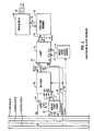
- Fig. 1 is a schematic illustration of the system for monitoring presence and use of EDP equipment, depicting a host system and plurality of remote machines with a power bus communication link.
- Fig. 2 is a functional block diagram of the hardware associated with each of the host and remote computer systems of Fig. 1 for effecting the system intercommunication of the invention.
- Fig. 3 is a functional block diagram of a computer program executed by a remote system of Fig. 1 on power-up.
- Fig. 4 is a functional block diagram of a next computer program executed by a remote system of Fig. 1 in response to an incoming interrogative message from the host computer.
- Fig. 5 is a functional block diagram of a computerized control program executed by the host system of Fig. 1.
- the system 10 is comprised of a central monitoring computer 12 and one or more representative remote electronic data processing machines 28, 30, 32, 34, 36 and 38.
- the invention is not intended to be limited to any particular type of host or remote computer, and, thus, admits to the application with personal computers, workstations and even mini computers or the like, such as that depicted at reference numeral 38.
- the central monitoring computer 12 generally serves the purpose of maintaining control and a database of information on all the other machines in the system 10, as will hereinafter be described in greater detail, including which computers are deployed in various uses throughout a given building, for example.
- the remote systems 28, 30, 32, 34, 36 and 38 receive power, as does the host system 12, via a common conventional 110 volt AC power bus 14, as represented by connections 17, 19, 21, 23, 25 and 27 to the remote systems and interconnections 18, 20, 22, 24 and 26 to the host system 12, such power conventionally being delivered through appropriate power transformers well known in the art.
- the system of the present invention alleviates the cost associated with cabling a network with specialized dedicated cabling using traditional LAN cabling or the like.
- FIG. 2 depicted therein is the hardware provided with each remote and host system in order to implement the aforementioned power line communication.
- the device depicted in Fig. 2 with respect to a given remote or host computer of Fig. 1 is attached to the particular computer bus (which conventionally includes a data, address and control bus lines 40, 42 and 44, respectively) via an I/O port 56.
- this I/O port may be implemented by a digital integrated circuit, such as a Motorola 6820 chip or the equivalent.
- This port 56 allows data, represented by arrow 48 and 64, to be transferred to and from the port 56 by using typical INP (ADDR) and OUT (ADDR) commands or equivalents well known in the art.
- the hardware communication device of Fig. 2 may be configured to interrupt the microprocessor of the given remote computer in the event of an incoming message, or, in the alternative, a simple polling scheme may be substituted.
- Selection logic 52 in response to address commands 50 from the particular computer, will generate chip select signals 54 and 68 for controlling the functions of the hardware system of Fig. 2 in a conventional manner.
- buffered bidirectional data flows in and out of the I/O port 56 to a uniform asynchronous receiver-transmitter or UART 70 such as an integrated circuit INTEL 8251 manufactured by the INTEL Corporation, or, in the alternative, some other serial/parallel conversion device as desired.
- a uniform asynchronous receiver-transmitter or UART 70 such as an integrated circuit INTEL 8251 manufactured by the INTEL Corporation, or, in the alternative, some other serial/parallel conversion device as desired.
- the microprocessor associated with the computer containing the Fig. 2 hardware will generate on the control bus 44 from time-to-time read-write signals 66 and clock signals 64 generating conventional read or write commands as required and for controlling the transmission and receiving rate of the system.
- a BAUD rate generator 62 receives this computer clock signal 60 and generates receive and transmit signals 72 delivered to the UART 70 for controlling the rate at which the digitized signals imposed on the power line 84 are transmitted or received.
- Outgoing serial messages generated by the computer are delivered on the transmission line 74 to a power line modem 78 which modulates them as shown by line 82 onto the power supply 80 of the particular computer and, thence, onto the power line 84 to which the computer is plugged in.
- incoming data on the power line 84 is routed to the power supply 80 and delivered on line 82 to the power line modem 78 wherein these signals are decoded, and delivered on the asynchronous receive line 76 to the UART 70.
- the power line modem may take the form of a NE5050 integrated circuit power line modem manufactured by the Signetics corporation or equivalent.
- the system provided herein is accordingly far superior to a system requiring establishment of a LAN and interconnection of each remote machine thereto.
- this approach is impractical due to prohibitive costs of cabling every machine in a building together.
- such an approach does not guarantee that an unconnected machine is not being used somewhere in the building.
- yet another problem with this approach arises when a machine configured as a public resource on the LAN becomes prey to anyone attempting to breach security.
- Fig. 3 software in a representative remote computer will consist of essentially two routines.
- the first, as shown in Fig. 3, is preferably entered and executed immediately after the computer is powered up and has executed a power on self-test routine or "POST".
- POST power on self-test routine
- FIG. 3 shows a routine prompting the user for a unique user I.D. as shown at block 94.
- the remote computer program will then preferably execute a sub-routine transmitting the thus prompted-for user I.D. and a unique machine identification code to the central monitoring computer 12 via the power line modem of Fig. 2 in the manner previously described.
- This step of machine and user I.D. transmission is shown in Fig. 3 at block 96.
- each remote computer may preferably have stored therein in BIOS, other ROM, in DASDI or the like, a unique identifying number associated with that particular remote computer.
- the particular remote computer may fetch from the known stored location this unique machine I.D. for modulation onto the power line.
- the routine executed on the remote computers will preferably pass control back to the operating system allowing normal use of the remote computer, as shown at block 98.
- the aforementioned second routine desirably executed by each remote control system is entered into in response to an incoming poll or interrupt from the central monitoring computer 12 via the power line.
- This incoming poll or interrupt interrogative from the host is schematically depicted in Fig. 4 at block 100.
- the correlative remote computer Upon decoding of this command off of the power line by the hardware of Fig. 2, the correlative remote computer, in response thereto, will derive and modulate onto the power line its respective machine and user I.D.'s, which were stored previously, for subsequent transmission to the central monitor 12.
- This program execution step is shown at block 102 of Fig. 4 whereupon control returns to the operating software, 104.
- routines may be burned into ROM of the representative remote computer or, in the alternative, embedded in the operating system or stored on DASDI as hidden files.
- ROM read only memory
- DASDI embedded in the operating system
- Fig. 5 depicted therein is a schematic functional block diagram of a computer program executed by the host system 12 for effecting the objects of the present invention.
- the central monitoring computer 12 in response to software control implementing the functional steps of Fig. 5, will monitor all power circuits to which remote computers, which are to be monitored, are connected for incoming messages from these computers.
- the host monitor 12 will also perform numerous additional functions to be hereinafter described, including the updating of its database or remote machines from the information contained in these incoming messages from the remote machine.
- the host computer 12 in response to program control, will provide functions allowing the operator to query the database for various items as will be described with reference to Fig. 5.
- the computer program executing on the host system 12 will commence as shown at block 106 whereupon the lines 18-26, Fig. 1, will be monitored by the host 12 for incoming signals as shown generally at blocks 108, 110 and 112. Upon receipt of incoming data from each respective remote computer regarding the machine and user I.D.'s, the host computer 12 will update an appropriate database 114 with this data. The host system operator may then interact with the host, as shown at block 116, to select any number of a plurality of functions to be performed by the remote system 12 in response to this user input, which is gererally shown at reference numeral 118.
- These tasks performable by the host system relating to the management of remote EDP systems include the choices of querying the database for machines which are currently in use, 120, querying the database for machines which have not been used for a specified period of time, 124, querying the database for a specific machine I.D. to determine that machine's status, 126, querying the database for a specific user I.D., for example, to determine which machine a user is accessing, 128, and a choice to exit a routine for maintenance, 130.
- these interactive usages of this data as generally shown at 118 of Fig. 5, are not intended to be so limited to only those functions depicted with reference to reference numerals 120-130. In other words, the invention lends itself to any number of applications of this data, and, thus, is not intended to be limited to only those described herein.
- any necessary polls in response thereto are generated by the host computer 12 and modulated onto the power line, as shown at block 132.
- these polls could, if desired, include not only commands to a particular remote computer to send back its machine and user I.D.'s, but could further be used for purposes of providing additional data or control to the selected remote computer.
- the operating software of the host system 12 will query at 134 whether it is desirable to exit the auditing routine. If the answer is affirmative, as shown at path 138, control will be returned at 140 to the operating system for further normal usage of the host 12.
- control routes through path 136 to continue the just-described cycle indefinitely, e.g. namely monitoring the various power lines and interacting with the data obtained therefrom.
Abstract
A plurality of electronic data processing machines (28 - 38) comprised of remote personal computers, workstations, or the like, and a central monitoring host computer 12 are interconnected to a conventional alternating current power bus 16 - 20. Each machine includes a power line modem for modulating and demodulating digitized data and control signals on to and off the power bus, respectively. The remote machines further include system software which digitizes a prompted-for user I.D. and respective unique machine I.D. code, stored in BIOS or other ROM, in the machine's operating system, or in DASDI in hidden files, and transmits, via modulation onto the power bus, these digitized codes to the host computer. The host computer includes software providing the functions of monitoring all power circuits for such encoded incoming machine and user I.D. information, for updating its database of machines with this incoming data, and further providing functions allowing the central monitoring computer operator to query the database and issue polling commands to selected remote equipmen. Each remote machine's software further includes routines to monitor the power bus for such incoming polls from the host and transmetting the machine and user I.D.'s previously stored to the central monitor in response to such polling requests.
Description
- This invention relates to systems and methods for monitoring electronic data processing equipment, for example for identification and tracking of such equipment disposed at remote locations.
- The ever-increasing presence of electronic data processing or "EDP" equipment in the modern office building brings with it the need to track the whereabouts and, in certain instances, use of such equipment.
- Current methods for accomplishing this objective typically are strictly and extremely manual labor intensive, requiring hours of inventory tracking personnel's time in tracking, record keeping, serial number checking and the like. Moreover, such current systems are not foolproof for numerous reasons. For example, a malevolent individual can easily move or remove EDP equipment without notifying the proper controlling authorities. This situation, symptomized by lost EDP assets and non-management approved use of such EDP assets, permeates industry today, and is even more severe in government and military installations, wherein simple unauthorized use of a machine may result in damage to national security beyond monetary measure.
- Numerous systems have been proposed for polling for various data, such as in the case of main frames interconnected to remote terminals and systems internal to a given personal computer which have been adapted to poll for presence of various adapter cards present on the bus. However, in the case of such main frame interconnections to remote terminals, typically a session must be established between the main frame and the remote terminals. Although it is typical to provide for security features regarding the interconnection between such main frames and remote computers, such interconnections are typically established through local area networks with associated dedicated, specialized and often expensive cabling, and the like, to establish the LAN.
- It is accordingly an object of the present invention to provide a system and method for monitoring location and usage of remotely disposed computer equipment which minimises the labor-intensive aspects associated with conventional monitoring systems and avoids the necessity of installing expensive local area networks or other cabling.
- According to the invention we provide a system for monitoring data processing equipment sharing a common power line, said system comprising at least one remote computer and a monitoring computer and being characterised in that the or each remote computer includes means for transferring coded signals to and from said power line and has a unique identification code associated therewith and said monitoring computer includes means for interrogating remote computers by applying appropriate identification codes to said power line and for receiving status information in response to such interrogation.
- We further provide a method for monitoring computer systems sharing a common power line comprising generating an encoded signal by at least one such computer system, modulating said encoded signal onto said power line by said at least one computer system, and decoding said encoded signal from said power line by a second on of said computer systems.
- In a preferred embodiment of the invention, a plurality of remote personal computers, workstations, or the like, and a central monitoring host computer are interconnected to a conventional alternating current power bus. Each machine includes a power line modem for modulating and demodulating digitized data and control signals on to and off the power bus, respectively. The remote machines further include system software which digitizes a prompted-for user I.D. and respective unique machine I.D. code, stored in BIOS or other ROM, in the machine's operating system, or in DASDI in hidden files, and transmits, via modulation onto the power bus, these digitized codes to the host computer. The host computer includes software providing the functions of monitoring all power circuits for such encoded incoming machine and user I.D. information, for updating its database of machines with this incoming data, and further providing functions allowing the central monitoring computer operator to query the database and issue polling commands to selected remote equipment. Each remote machine's software further includes routines to monitor the power bus for such incoming polls from the host and transmitting the machine and user I.D.'s previously stored to the central monitor in response to such polling requests.
- In order that the invention may be well understood, this embodiment thereof will now be described with reference to the accompanying drawings, in which:
- Fig. 1 is a schematic illustration of the system for monitoring presence and use of EDP equipment, depicting a host system and plurality of remote machines with a power bus communication link.
- Fig. 2 is a functional block diagram of the hardware associated with each of the host and remote computer systems of Fig. 1 for effecting the system intercommunication of the invention.
- Fig. 3 is a functional block diagram of a computer program executed by a remote system of Fig. 1 on power-up.
- Fig. 4 is a functional block diagram of a next computer program executed by a remote system of Fig. 1 in response to an incoming interrogative message from the host computer.
- Fig. 5 is a functional block diagram of a computerized control program executed by the host system of Fig. 1.
- Described herein is a system for monitoring presence and use of electronic data processing equipment disposed at locations remotely of a host monitoring system. With reference to Fig. 1, the
system 10, as broadly depicted therein, is comprised of acentral monitoring computer 12 and one or more representative remote electronicdata processing machines reference numeral 38. Thecentral monitoring computer 12 generally serves the purpose of maintaining control and a database of information on all the other machines in thesystem 10, as will hereinafter be described in greater detail, including which computers are deployed in various uses throughout a given building, for example. - Still referring to Fig. 1, it will noted that the
remote systems host system 12, via a common conventional 110 voltAC power bus 14, as represented byconnections interconnections host system 12, such power conventionally being delivered through appropriate power transformers well known in the art. - In addition to power to the various host and remote systems being delivered on the power bus, as just described, it is an important feature of the invention that communication is also provided through these power line connections via power line modems, which are deployed in a manner to be hereinafter described to ensure that a remote system in use remains. As previously described, by employing the power bus, the system of the present invention alleviates the cost associated with cabling a network with specialized dedicated cabling using traditional LAN cabling or the like.
- Referring now to Fig. 2, depicted therein is the hardware provided with each remote and host system in order to implement the aforementioned power line communication. The device depicted in Fig. 2 with respect to a given remote or host computer of Fig. 1 is attached to the particular computer bus (which conventionally includes a data, address and control bus lines 40, 42 and 44, respectively) via an I/
O port 56. In one implementation, this I/O port may be implemented by a digital integrated circuit, such as a Motorola 6820 chip or the equivalent. Thisport 56 allows data, represented byarrow port 56 by using typical INP (ADDR) and OUT (ADDR) commands or equivalents well known in the art. Alternatively, the hardware device depicted in Fig. 2 could also be mapped to unused memory of its respective computer system and accessed using commands such as STORE (ADDR) and LOAD (ADDR) commands also well known in the art. The hardware communication device of Fig. 2 may be configured to interrupt the microprocessor of the given remote computer in the event of an incoming message, or, in the alternative, a simple polling scheme may be substituted.Selection logic 52, in response toaddress commands 50 from the particular computer, will generate chipselect signals - Still referring to Fig. 2, buffered bidirectional data flows in and out of the I/
O port 56 to a uniform asynchronous receiver-transmitter or UART 70 such as an integrated circuit INTEL 8251 manufactured by the INTEL Corporation, or, in the alternative, some other serial/parallel conversion device as desired. Again, as is conventional, the microprocessor associated with the computer containing the Fig. 2 hardware will generate on the control bus 44 from time-to-time read-write signals 66 andclock signals 64 generating conventional read or write commands as required and for controlling the transmission and receiving rate of the system. With respect to the latter, aBAUD rate generator 62 receives thiscomputer clock signal 60 and generates receive and transmitsignals 72 delivered to the UART 70 for controlling the rate at which the digitized signals imposed on thepower line 84 are transmitted or received. Outgoing serial messages generated by the computer are delivered on the transmission line 74 to apower line modem 78 which modulates them as shown byline 82 onto the power supply 80 of the particular computer and, thence, onto thepower line 84 to which the computer is plugged in. Similarly, incoming data on thepower line 84 is routed to the power supply 80 and delivered online 82 to thepower line modem 78 wherein these signals are decoded, and delivered on theasynchronous receive line 76 to the UART 70. In a conventional manner, this received data will thence be interpreted by the microprocessor system of the particular computer for use with the software program executing on the computer, in a manner to be hereinafter described. In a preferred embodiment, the power line modem may take the form of a NE5050 integrated circuit power line modem manufactured by the Signetics corporation or equivalent. - The system provided herein is accordingly far superior to a system requiring establishment of a LAN and interconnection of each remote machine thereto. As noted, this approach is impractical due to prohibitive costs of cabling every machine in a building together. Furthermore, such an approach does not guarantee that an unconnected machine is not being used somewhere in the building. Moreover, yet another problem with this approach arises when a machine configured as a public resource on the LAN becomes prey to anyone attempting to breach security.
- Referring now to the computer programs necessary to be executed on the various computer systems of Fig. 1 to implement the present invention, referring more particularly to Figs. 3 and 4, it will be noted that software in a representative remote computer will consist of essentially two routines. The first, as shown in Fig. 3, is preferably entered and executed immediately after the computer is powered up and has executed a power on self-test routine or "POST". This is shown in Fig. 3 by
blocks block 92. After execution of the POST, the preferred routine executed by the remote computers will preferably include a routine prompting the user for a unique user I.D. as shown atblock 94. The remote computer program will then preferably execute a sub-routine transmitting the thus prompted-for user I.D. and a unique machine identification code to thecentral monitoring computer 12 via the power line modem of Fig. 2 in the manner previously described. This step of machine and user I.D. transmission is shown in Fig. 3 atblock 96. It will be noted at this point that each remote computer may preferably have stored therein in BIOS, other ROM, in DASDI or the like, a unique identifying number associated with that particular remote computer. Thus, at an appropriate time, either prompted by an interrupt from thehost computer 12 or in response to a polling procedure, the particular remote computer, through execution of conventional software employing the data, address and control busses 40-44, may fetch from the known stored location this unique machine I.D. for modulation onto the power line. Finally, with respect to Fig. 3, upon such transmission of the machine and user I.D.'s by the remote system to thehost system 12, upon completion of this task, the routine executed on the remote computers will preferably pass control back to the operating system allowing normal use of the remote computer, as shown atblock 98. - The aforementioned second routine desirably executed by each remote control system is entered into in response to an incoming poll or interrupt from the
central monitoring computer 12 via the power line. This incoming poll or interrupt interrogative from the host is schematically depicted in Fig. 4 atblock 100. Upon decoding of this command off of the power line by the hardware of Fig. 2, the correlative remote computer, in response thereto, will derive and modulate onto the power line its respective machine and user I.D.'s, which were stored previously, for subsequent transmission to thecentral monitor 12. This program execution step is shown atblock 102 of Fig. 4 whereupon control returns to the operating software, 104. As hereinbefore noted, these routines, as well as the machine I.D., may be burned into ROM of the representative remote computer or, in the alternative, embedded in the operating system or stored on DASDI as hidden files. As aforementioned, conventionally, it would be expected, however, with respect to the user I.D. that this would be entered by the particular user in response to a prompt. Once the aforementioned steps have been executed by the remote computer, it will resume with normal operation as indicated atblock 104. - Referring now to Fig. 5, depicted therein is a schematic functional block diagram of a computer program executed by the
host system 12 for effecting the objects of the present invention. It will be recalled that thecentral monitoring computer 12 in response to software control implementing the functional steps of Fig. 5, will monitor all power circuits to which remote computers, which are to be monitored, are connected for incoming messages from these computers. Broadly, also in response to execution of the appropriate program represented by Fig. 5, the host monitor 12 will also perform numerous additional functions to be hereinafter described, including the updating of its database or remote machines from the information contained in these incoming messages from the remote machine. Further, thehost computer 12 in response to program control, will provide functions allowing the operator to query the database for various items as will be described with reference to Fig. 5. - Referring now in more detail to Fig. 5, the computer program executing on the
host system 12 will commence as shown atblock 106 whereupon the lines 18-26, Fig. 1, will be monitored by thehost 12 for incoming signals as shown generally atblocks host computer 12 will update anappropriate database 114 with this data. The host system operator may then interact with the host, as shown atblock 116, to select any number of a plurality of functions to be performed by theremote system 12 in response to this user input, which is gererally shown atreference numeral 118. - These tasks performable by the host system relating to the management of remote EDP systems include the choices of querying the database for machines which are currently in use, 120, querying the database for machines which have not been used for a specified period of time, 124, querying the database for a specific machine I.D. to determine that machine's status, 126, querying the database for a specific user I.D., for example, to determine which machine a user is accessing, 128, and a choice to exit a routine for maintenance, 130. It should be readily apparent that once the data regarding machine and user I.D. has been received by the
remote computer 12, these interactive usages of this data, as generally shown at 118 of Fig. 5, are not intended to be so limited to only those functions depicted with reference to reference numerals 120-130. In other words, the invention lends itself to any number of applications of this data, and, thus, is not intended to be limited to only those described herein. - With continued reference to Fig. 5, once these user initiated functions, 118, have been performed, any necessary polls in response thereto are generated by the
host computer 12 and modulated onto the power line, as shown atblock 132. It will be noted that these polls could, if desired, include not only commands to a particular remote computer to send back its machine and user I.D.'s, but could further be used for purposes of providing additional data or control to the selected remote computer. After the poll or interrupt at 132 has been delivered, the operating software of thehost system 12 will query at 134 whether it is desirable to exit the auditing routine. If the answer is affirmative, as shown atpath 138, control will be returned at 140 to the operating system for further normal usage of thehost 12. Alternatively, once these polls have been transmitted as necessary to remote machines requiring status updates, if an indication is received at 134 that an exit is not desired, i.e. so long as the executing monitoring program is not taken off line for machine maintenance, the control routes throughpath 136 to continue the just-described cycle indefinitely, e.g. namely monitoring the various power lines and interacting with the data obtained therefrom.
Claims (14)
1. A system for monitoring data processing equipment sharing a common power line, said system comprising at least one remote computer and a monitoring computer and being characterised in that the or each remote computer includes means for transferring coded signals to and from said power line and has a unique identification code associated therewith and said monitoring computer includes means for interrogating remote computers by applying appropriate identification codes to said power line and for receiving status information in response to such interrogation.
2. A system as claimed in claim 1 in which said monitoring computer includes means for generating and modulating onto said power line interrogative polling command requests to cause at least one of said remote computer systems to modulate its respective unique identification code onto said power line.
4. A system as claimed in claim 3 wherein said monitoring computer includes a database for storing demodulated encoded signals from the or each remote computer.
3. A system as claimed in claim 2 wherein each remote computer is adapted to generate, in response to said polling command, a unique user identification associated with a user interacting therewith.
5. A system as claimed in claim 4 wherein said database includes retrieval means responsive to input identifying a user for retrieving selected ones of said user identifications associated with stored identification codes.
6. A system as claimed in any preceding claim in which said monitoring computer further comprises means for determining duration of time a respective one of said remote computer systems is in operation as a function of said coded signals.
7. A method for monitoring computer systems sharing a common power line, comprising generating an encoded signal by at least one such computer system, modulating said encoded signal onto said power line by said at least one computer system, and decoding said encoded signal from said power line by a second one of said computer systems.
8. A method as claimed in claim 7 wherein said encoded signal is a digitized code uniquely associated with each said at least one first computer system.
9. A method as claimed in claim 8 wherein said at least one first computer system comprises a plurality of first computers, and wherein each of said first computer systems generates and modulates onto said power line a different said unique digitized code.
10. A method as claimed in claim 9 including generating an interrogative polling request command with said second system and modulating said command onto said power line.
11. A method as claimed in claim 10 further including decoding with said at least one first computer system said command, and wherein said generating an encoded signal is in response to said decoded command.
12. A method as claimed in claim 11 further including detecting with said second computer system in response to a plurality of said encoded signals the duration of time said power is provided to said at least one first computer system.
13. A method as claimed in claim 12 wherein said step of generating an encoded signal further comprises generating a digital code uniquely associated with each user of a respective one of said at least one first computer systems.
14. A method as claimed in claim 13 further including storing said encoded signals at said second computer system; and retrieving selected ones of said stored encoded signals as a function of user input.
Applications Claiming Priority (2)
| Application Number | Priority Date | Filing Date | Title |
|---|---|---|---|
| US520578 | 1990-05-08 | ||
| US07/520,578 US5072370A (en) | 1990-05-08 | 1990-05-08 | System and method for monitoring electronic data processing equipment |
Publications (2)
| Publication Number | Publication Date |
|---|---|
| EP0456395A2 true EP0456395A2 (en) | 1991-11-13 |
| EP0456395A3 EP0456395A3 (en) | 1993-09-01 |
Family
ID=24073217
Family Applications (1)
| Application Number | Title | Priority Date | Filing Date |
|---|---|---|---|
| EP19910303842 Withdrawn EP0456395A3 (en) | 1990-05-08 | 1991-04-26 | System and method for monitoring electronic data processing equipment |
Country Status (3)
| Country | Link |
|---|---|
| US (1) | US5072370A (en) |
| EP (1) | EP0456395A3 (en) |
| JP (1) | JPH077368B2 (en) |
Cited By (4)
| Publication number | Priority date | Publication date | Assignee | Title |
|---|---|---|---|---|
| EP0585154A2 (en) * | 1992-07-31 | 1994-03-02 | Sextant Avionique | Device for the dynamic display of information about an electronic system with a variable configuration and/or composition |
| GB2287558A (en) * | 1994-03-15 | 1995-09-20 | Fujitsu Ltd | Computer network supervision |
| WO1996009613A1 (en) * | 1994-09-19 | 1996-03-28 | Hedstroem Mats Holger Goeran | A control and registration system |
| WO1997020295A1 (en) * | 1995-11-28 | 1997-06-05 | Rolf Edman | A controlling and/or registration system |
Families Citing this family (41)
| Publication number | Priority date | Publication date | Assignee | Title |
|---|---|---|---|---|
| GB2249460B (en) * | 1990-09-19 | 1994-06-29 | Intel Corp | Network providing common access to dissimilar hardware interfaces |
| US5452344A (en) * | 1992-05-29 | 1995-09-19 | Datran Systems Corporation | Communication over power lines |
| JPH0612288A (en) * | 1992-06-29 | 1994-01-21 | Hitachi Ltd | Information processing system and monitoring method therefor |
| US5640513A (en) * | 1993-01-22 | 1997-06-17 | International Business Machines Corporation | Notification of disconnected service machines that have stopped running |
| CN1092538A (en) * | 1993-03-16 | 1994-09-21 | Ht研究公司 | A kind of casing that is used for multicomputer system |
| US5694595A (en) * | 1993-12-23 | 1997-12-02 | International Business Machines, Corporation | Remote user profile management administration in a computer network |
| US5864698A (en) * | 1994-08-24 | 1999-01-26 | Packard Bell Nec | Disk based bios |
| US5491791A (en) * | 1995-01-13 | 1996-02-13 | International Business Machines Corporation | System and method for remote workstation monitoring within a distributed computing environment |
| US6112237A (en) * | 1996-11-26 | 2000-08-29 | Global Maintech, Inc. | Electronic monitoring system and method for externally monitoring processes in a computer system |
| SE521041C2 (en) | 1997-05-28 | 2003-09-23 | Ericsson Telefon Ab L M | Method for optimizing transaction protocols within a distributed database |
| US6205498B1 (en) * | 1998-04-01 | 2001-03-20 | Microsoft Corporation | Method and system for message transfer session management |
| US6529932B1 (en) | 1998-04-01 | 2003-03-04 | Microsoft Corporation | Method and system for distributed transaction processing with asynchronous message delivery |
| US6311291B1 (en) * | 1998-08-12 | 2001-10-30 | Pc-Tel, Inc. | Remote modem control and diagnostic system and method |
| US7486648B1 (en) * | 1999-10-11 | 2009-02-03 | Park Tours, Inc. | Wireless extension of local area networks |
| US20070178912A1 (en) * | 2000-03-14 | 2007-08-02 | Robert Baranowski | System and method for enhancing user experience in a wide-area facility having a distributed, bounded environment |
| US7073083B2 (en) | 2001-07-18 | 2006-07-04 | Thomas Licensing | Method and system for providing emergency shutdown of a malfunctioning device |
| JP2003172578A (en) * | 2001-12-07 | 2003-06-20 | Hitachi Ltd | Network-ready home electric appliances, and system and service for checking home electric appliances |
| JP4149240B2 (en) * | 2002-07-16 | 2008-09-10 | シャープ株式会社 | Electrical device management method, management apparatus, program thereof, and electrical device management system |
| KR100505230B1 (en) * | 2002-12-10 | 2005-08-03 | 엘지전자 주식회사 | Home Network System and Home Appliance Reducing Method for the Same |
| US7424525B2 (en) * | 2003-06-30 | 2008-09-09 | Microsoft Corporation | Managing headless computer systems |
| US7529728B2 (en) * | 2003-09-23 | 2009-05-05 | Salesforce.Com, Inc. | Query optimization in a multi-tenant database system |
| US7779039B2 (en) | 2004-04-02 | 2010-08-17 | Salesforce.Com, Inc. | Custom entities and fields in a multi-tenant database system |
| US8543566B2 (en) | 2003-09-23 | 2013-09-24 | Salesforce.Com, Inc. | System and methods of improving a multi-tenant database query using contextual knowledge about non-homogeneously distributed tenant data |
| ITMI20050677A1 (en) * | 2005-04-18 | 2006-10-19 | Sisvel Spa | CONNECTION SYSTEM BETWEEN A SERVICE CENTER AND A PLURALITY OF TV RECEPTION DEVICES |
| US20070055740A1 (en) * | 2005-08-23 | 2007-03-08 | Luciani Luis E | System and method for interacting with a remote computer |
| WO2007030796A2 (en) | 2005-09-09 | 2007-03-15 | Salesforce.Com, Inc. | Systems and methods for exporting, publishing, browsing and installing on-demand applications in a multi-tenant database environment |
| US8387138B2 (en) * | 2006-03-21 | 2013-02-26 | At&T Intellectual Property I, L.P. | Security scanning system and method |
| US9361366B1 (en) | 2008-06-03 | 2016-06-07 | Salesforce.Com, Inc. | Method and system for controlling access to a multi-tenant database system using a virtual portal |
| US8473518B1 (en) | 2008-07-03 | 2013-06-25 | Salesforce.Com, Inc. | Techniques for processing group membership data in a multi-tenant database system |
| US8473469B1 (en) | 2008-08-25 | 2013-06-25 | Salesforce.Com, Inc. | Techniques for implementing batch processing in a multi-tenant on-demand database system |
| US8296321B2 (en) * | 2009-02-11 | 2012-10-23 | Salesforce.Com, Inc. | Techniques for changing perceivable stimuli associated with a user interface for an on-demand database service |
| US10482425B2 (en) | 2009-09-29 | 2019-11-19 | Salesforce.Com, Inc. | Techniques for managing functionality changes of an on-demand database system |
| US8443366B1 (en) | 2009-12-11 | 2013-05-14 | Salesforce.Com, Inc. | Techniques for establishing a parallel processing framework for a multi-tenant on-demand database system |
| US8776067B1 (en) | 2009-12-11 | 2014-07-08 | Salesforce.Com, Inc. | Techniques for utilizing computational resources in a multi-tenant on-demand database system |
| US8977675B2 (en) | 2010-03-26 | 2015-03-10 | Salesforce.Com, Inc. | Methods and systems for providing time and date specific software user interfaces |
| US9189090B2 (en) | 2010-03-26 | 2015-11-17 | Salesforce.Com, Inc. | Techniques for interpreting signals from computer input devices |
| US8595181B2 (en) | 2010-05-03 | 2013-11-26 | Salesforce.Com, Inc. | Report preview caching techniques in a multi-tenant database |
| US8977739B2 (en) | 2010-05-03 | 2015-03-10 | Salesforce.Com, Inc. | Configurable frame work for testing and analysis of client-side web browser page performance |
| US8972431B2 (en) | 2010-05-06 | 2015-03-03 | Salesforce.Com, Inc. | Synonym supported searches |
| US8819632B2 (en) | 2010-07-09 | 2014-08-26 | Salesforce.Com, Inc. | Techniques for distributing information in a computer network related to a software anomaly |
| US9069901B2 (en) | 2010-08-19 | 2015-06-30 | Salesforce.Com, Inc. | Software and framework for reusable automated testing of computer software systems |
Citations (4)
| Publication number | Priority date | Publication date | Assignee | Title |
|---|---|---|---|---|
| US3702460A (en) * | 1971-11-30 | 1972-11-07 | John B Blose | Communications system for electric power utility |
| EP0047089A1 (en) * | 1980-09-01 | 1982-03-10 | South Eastern Electricity Board | Method of and apparatus for controlling loads on an electrical power supply |
| EP0201253A2 (en) * | 1985-05-09 | 1986-11-12 | THORN EMI Patents Limited | Power line communications system |
| GB2229025A (en) * | 1989-03-09 | 1990-09-12 | Elocktronics Limited | Safeguarding electrical apparatus |
Family Cites Families (7)
| Publication number | Priority date | Publication date | Assignee | Title |
|---|---|---|---|---|
| US4218738A (en) * | 1978-05-05 | 1980-08-19 | International Business Machines Corporation | Method for authenticating the identity of a user of an information system |
| US4484271A (en) * | 1979-01-31 | 1984-11-20 | Honeywell Information Systems Inc. | Microprogrammed system having hardware interrupt apparatus |
| US4357605A (en) * | 1980-04-08 | 1982-11-02 | Metallurgical Research, Inc. | Cash flow monitoring system |
| US4540890A (en) * | 1982-05-24 | 1985-09-10 | Galber Automazione E | System for selectively addressing electrical control signals from a control unit to a plurality of remote units |
| JPS6249466A (en) * | 1985-08-28 | 1987-03-04 | Nec Corp | User terminal control system |
| JPS62190948A (en) * | 1986-02-18 | 1987-08-21 | Nisshin Sangyo Kk | Computer network system using power line carrier |
| JPS63196197A (en) * | 1987-02-09 | 1988-08-15 | Toshiba Heating Appliances Co | Carrier control system power line |
-
1990
- 1990-05-08 US US07/520,578 patent/US5072370A/en not_active Expired - Fee Related
-
1991
- 1991-04-26 JP JP3123126A patent/JPH077368B2/en not_active Expired - Lifetime
- 1991-04-26 EP EP19910303842 patent/EP0456395A3/en not_active Withdrawn
Patent Citations (4)
| Publication number | Priority date | Publication date | Assignee | Title |
|---|---|---|---|---|
| US3702460A (en) * | 1971-11-30 | 1972-11-07 | John B Blose | Communications system for electric power utility |
| EP0047089A1 (en) * | 1980-09-01 | 1982-03-10 | South Eastern Electricity Board | Method of and apparatus for controlling loads on an electrical power supply |
| EP0201253A2 (en) * | 1985-05-09 | 1986-11-12 | THORN EMI Patents Limited | Power line communications system |
| GB2229025A (en) * | 1989-03-09 | 1990-09-12 | Elocktronics Limited | Safeguarding electrical apparatus |
Cited By (7)
| Publication number | Priority date | Publication date | Assignee | Title |
|---|---|---|---|---|
| EP0585154A2 (en) * | 1992-07-31 | 1994-03-02 | Sextant Avionique | Device for the dynamic display of information about an electronic system with a variable configuration and/or composition |
| EP0585154A3 (en) * | 1992-07-31 | 1994-06-29 | Sextant Avionique | Device for the dynamic display of information about an electronic system with a variable configuration and/or composition |
| GB2287558A (en) * | 1994-03-15 | 1995-09-20 | Fujitsu Ltd | Computer network supervision |
| GB2287558B (en) * | 1994-03-15 | 1998-03-11 | Fujitsu Ltd | Supervising system in a computer network |
| US5748880A (en) * | 1994-03-15 | 1998-05-05 | Fujitsu Limited | Computer-supervising system |
| WO1996009613A1 (en) * | 1994-09-19 | 1996-03-28 | Hedstroem Mats Holger Goeran | A control and registration system |
| WO1997020295A1 (en) * | 1995-11-28 | 1997-06-05 | Rolf Edman | A controlling and/or registration system |
Also Published As
| Publication number | Publication date |
|---|---|
| US5072370A (en) | 1991-12-10 |
| EP0456395A3 (en) | 1993-09-01 |
| JPH04229349A (en) | 1992-08-18 |
| JPH077368B2 (en) | 1995-01-30 |
Similar Documents
| Publication | Publication Date | Title |
|---|---|---|
| EP0456395A2 (en) | System and method for monitoring electronic data processing equipment | |
| CA2325712C (en) | Rfid tagging system for network assets | |
| US5367670A (en) | Computer system manager for monitoring events and operating parameters and generating alerts | |
| US5684957A (en) | Network management system for detecting and displaying a security hole | |
| CA1246747A (en) | Apparatus for controlling the use of computer software | |
| EP1141804B1 (en) | A control device for a computer, use of a control device, a computer comprising a control device, and a method of connecting and disconnecting units in a computer | |
| US6708297B1 (en) | Method and system for monitoring errors on field replaceable units | |
| EP0520766A2 (en) | Innate bus monitor for computer system manager | |
| CN101482987A (en) | Central control and management method for outdoor communication machine room door based on communication network | |
| TW343301B (en) | An information security system for tracing the information outflow and a method for tracing the same | |
| CN107392264A (en) | Eletronic data management system and eletronic data management method | |
| CN108408362A (en) | A kind of intelligent transportation monitoring system and monitoring method for conveyer belt | |
| US6315198B1 (en) | Key cabinet for equipping an access control system and access control method and system using this key cabinet | |
| US4654638A (en) | Security monitoring system | |
| CN111428220A (en) | Mobile terminal office system based on remote collaboration platform | |
| KR101901644B1 (en) | Apparatus for managing universal subscriber identity module and monitoring program | |
| CN113888065A (en) | U-bit level equipment monitoring method, system and device and computer equipment | |
| JPH11203433A (en) | Non-contact type ic card system and method for processing trouble in the ic card system | |
| JPH09179828A (en) | Device for assigning user in computer network | |
| JP2007179210A (en) | Service-providing system, interactive display device, and service-providing method | |
| EP0155133A2 (en) | Manufacturing control system | |
| CN116962072B (en) | Automatic operation and maintenance method for secondary safety protection equipment of power dispatching data network | |
| CN112272160B (en) | Host security information calling method, system, intelligent terminal and computer storage medium | |
| CN110677412A (en) | Network security protection method and device for data downloading | |
| KR100717400B1 (en) | patrol checking system |
Legal Events
| Date | Code | Title | Description |
|---|---|---|---|
| PUAI | Public reference made under article 153(3) epc to a published international application that has entered the european phase |
Free format text: ORIGINAL CODE: 0009012 |
|
| AK | Designated contracting states |
Kind code of ref document: A2 Designated state(s): DE FR GB |
|
| 17P | Request for examination filed |
Effective date: 19911219 |
|
| PUAL | Search report despatched |
Free format text: ORIGINAL CODE: 0009013 |
|
| AK | Designated contracting states |
Kind code of ref document: A3 Designated state(s): DE FR GB |
|
| STAA | Information on the status of an ep patent application or granted ep patent |
Free format text: STATUS: THE APPLICATION IS DEEMED TO BE WITHDRAWN |
|
| 18D | Application deemed to be withdrawn |
Effective date: 19931102 |