EP0453995A2 - Optical disc recording apparatus - Google Patents
Optical disc recording apparatus Download PDFInfo
- Publication number
- EP0453995A2 EP0453995A2 EP91106349A EP91106349A EP0453995A2 EP 0453995 A2 EP0453995 A2 EP 0453995A2 EP 91106349 A EP91106349 A EP 91106349A EP 91106349 A EP91106349 A EP 91106349A EP 0453995 A2 EP0453995 A2 EP 0453995A2
- Authority
- EP
- European Patent Office
- Prior art keywords
- optical disc
- signals
- disc
- recording apparatus
- optical
- Prior art date
- Legal status (The legal status is an assumption and is not a legal conclusion. Google has not performed a legal analysis and makes no representation as to the accuracy of the status listed.)
- Granted
Links
Images

Classifications
-
- G—PHYSICS
- G11—INFORMATION STORAGE
- G11B—INFORMATION STORAGE BASED ON RELATIVE MOVEMENT BETWEEN RECORD CARRIER AND TRANSDUCER
- G11B7/00—Recording or reproducing by optical means, e.g. recording using a thermal beam of optical radiation by modifying optical properties or the physical structure, reproducing using an optical beam at lower power by sensing optical properties; Record carriers therefor
- G11B7/12—Heads, e.g. forming of the optical beam spot or modulation of the optical beam
- G11B7/125—Optical beam sources therefor, e.g. laser control circuitry specially adapted for optical storage devices; Modulators, e.g. means for controlling the size or intensity of optical spots or optical traces
- G11B7/126—Circuits, methods or arrangements for laser control or stabilisation
-
- G—PHYSICS
- G11—INFORMATION STORAGE
- G11B—INFORMATION STORAGE BASED ON RELATIVE MOVEMENT BETWEEN RECORD CARRIER AND TRANSDUCER
- G11B19/00—Driving, starting, stopping record carriers not specifically of filamentary or web form, or of supports therefor; Control thereof; Control of operating function ; Driving both disc and head
- G11B19/02—Control of operating function, e.g. switching from recording to reproducing
- G11B19/04—Arrangements for preventing, inhibiting, or warning against double recording on the same blank or against other recording or reproducing malfunctions
-
- G—PHYSICS
- G11—INFORMATION STORAGE
- G11B—INFORMATION STORAGE BASED ON RELATIVE MOVEMENT BETWEEN RECORD CARRIER AND TRANSDUCER
- G11B19/00—Driving, starting, stopping record carriers not specifically of filamentary or web form, or of supports therefor; Control thereof; Control of operating function ; Driving both disc and head
- G11B19/02—Control of operating function, e.g. switching from recording to reproducing
- G11B19/12—Control of operating function, e.g. switching from recording to reproducing by sensing distinguishing features of or on records, e.g. diameter end mark
-
- G—PHYSICS
- G11—INFORMATION STORAGE
- G11B—INFORMATION STORAGE BASED ON RELATIVE MOVEMENT BETWEEN RECORD CARRIER AND TRANSDUCER
- G11B19/00—Driving, starting, stopping record carriers not specifically of filamentary or web form, or of supports therefor; Control thereof; Control of operating function ; Driving both disc and head
- G11B19/20—Driving; Starting; Stopping; Control thereof
- G11B19/28—Speed controlling, regulating, or indicating
-
- G—PHYSICS
- G11—INFORMATION STORAGE
- G11B—INFORMATION STORAGE BASED ON RELATIVE MOVEMENT BETWEEN RECORD CARRIER AND TRANSDUCER
- G11B7/00—Recording or reproducing by optical means, e.g. recording using a thermal beam of optical radiation by modifying optical properties or the physical structure, reproducing using an optical beam at lower power by sensing optical properties; Record carriers therefor
- G11B7/004—Recording, reproducing or erasing methods; Read, write or erase circuits therefor
- G11B7/0045—Recording
-
- G—PHYSICS
- G11—INFORMATION STORAGE
- G11B—INFORMATION STORAGE BASED ON RELATIVE MOVEMENT BETWEEN RECORD CARRIER AND TRANSDUCER
- G11B7/00—Recording or reproducing by optical means, e.g. recording using a thermal beam of optical radiation by modifying optical properties or the physical structure, reproducing using an optical beam at lower power by sensing optical properties; Record carriers therefor
- G11B7/08—Disposition or mounting of heads or light sources relatively to record carriers
- G11B7/09—Disposition or mounting of heads or light sources relatively to record carriers with provision for moving the light beam or focus plane for the purpose of maintaining alignment of the light beam relative to the record carrier during transducing operation, e.g. to compensate for surface irregularities of the latter or for track following
- G11B7/0945—Methods for initialising servos, start-up sequences
Definitions
- This invention relates to an optical recording apparatus in which a recordable optical disc is used as the recording medium. More particularly, it relates to an optical disc recording apparatus which is provided with decision means for deciding if the optical disc attached to the optical disc recording apparatus is a pre-recorded optical disc, that is a disk on which information signals have been recorded, or an unrecorded disc.
- disc-shaped recording media such as optical discs or magneto-optical discs, utilizing optical or magneto-optical signal recording/reproducing methods, have been developed and presented to the market.
- These disc-shaped recording media include read-only-memory (ROM) type recording media, such as compact discs (CDs), write-once type recording media, or which data writing may be made only once by the user, and overwrite type recording media, on which data overwriting may be made, such as magneto-optical discs.
- ROM read-only-memory
- CDs compact discs
- overwrite type recording media on which data overwriting may be made, such as magneto-optical discs.
- the rotational speed of a spindle of a disc driving device adapted for rotating the optical disc is controlled for rotating the optical disc at a constant angular velocity or at a constant linear velocity.
- the optical disc rotated by the disc driving device is irradiated with a laser light from a semiconductor laser enclosed within the optical head, while the return laser light irradiated on and reflected back from the optical disc is detected by a photodetector enclosed within the optical head for recording/reproducing the information on or from the optical disc.
- the optical head also performs focusing control and tracking control for the laser light on the basis of the detection output obtained upon detection of the return laser light from the optical disc by the photodetector.
- the optical disc recording apparatus in which the write-once type optical disc is used as the recording medium, if a pre-recorded optical disc is inadvertently attached to the optical disc recording apparatus for recording information signals thereon, without ascertaining in advance if the disc is an unrecorded disc or a pre-recorded disc, the result is that information signals are overwritten on and destruct the pre-recorded information signals.
- the optical disc recording apparatus is an apparatus in which an optical disc, on which information signals can be recorded, is used as the recording medium.
- the optical disc recording apparatus includes a peak-holding circuit for holding the peak value of the reproduced RF signal, a bottom-holding circuit for holding the bottom value of the reproduced RF signal, and a decision circuit for deciding if the optical disc is or is not an unrecorded disc on the basis of the peak value from the peak-holding circuit and the bottom value from the bottom-holding circuit.
- optical disc recording apparatus is adapted for deciding if the attached optical disc is an unused disc on the basis of the peak value held in the peak-holding means and the bottom value held in the bottom-holding means.
- Fig. 1 is a block diagram showing an arrangement of an optical recording apparatus according to the present invention.
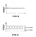
- Fig. 2 is a waveform diagram showing the reproduced RF signals obtained from an unrecorded optical disc.
- Fig. 3 is a waveform diagram showing the reproduced RF signals obtained from a pre-recorded optical disc.
- the present invention will be hereinafter explained with reference to a preferred embodiment in which it is applied to an optical recording apparatus making use of a write once type optical disc 1 as the recording medium.
- an optical disc 1 is rotationally driven under a rotational driving force of a spindle motor 3 for scanning a recording track on the disc 1 by a laser beam from an optical head 10 for optically recording digital data according to a predetermined data format.
- the optical recording medium herein the write once type optical disc, may be formed of an organic dye base material or a Te base metallic material.
- a laser beam radiated from a laser diode 11 as a laser light source is collimated by a collimating lens 12 so as to be converged on the signal recording surface of the optical disc 1 by means of a beam splitter 13 and an objective lens 14.
- the laser beam radiated from the laser diode 11 is modulated at the laser diode 11 by information signals to be recorded on the optical disc 1 and, when reproducing the signals from the optical disc 1, the laser beam becomes a dc laser beam having an output level lower than that for recording.
- the objective lens 14 may be moved by a biaxial driving unit, including driving coils 19 and 20, in a direction along the optical axis of the objective lens 14 and in a direction normal to the optical axis, that is along the radius of the optical disc 1.
- the photodetector 16 has a four-segment light receiving sections, and light pickup signals from these light receiving section is supplied by means of an amplifier 17 to a matrix circuit 18 where the sum and the difference of the light pickup signals are taken to produce reproduced RF signals, focusing error signals, tracking error signals or push-pull signals, as output signals.
- the focusing error signals (FE signals) from the matrix circuit 18 are supplied by means of a phase compensation circuit 23 and a driving circuit 24 to the driving coil 19 of the biaxial driving unit.
- FE signals focusing error signals
- the tracking error signal (TE signal) from the matrix circuit 18 is supplied to the driving coil 20 of the biaxial driving unit by means of a gain switching circuit 25, phase compensation circuit 26 and a driving circuit 28.
- the objective lens 14 is moved in a direction orthogonal to the optical axis by way of performing tracking servo in a known manner.
- the magnet facing the driving coil 20 the aforementioned magnet facing the driving coil 19 may be employed.
- the gain switching circuit 25 is controlled by a control signal from a CPU 50 as later described for switching the tracking servo gain between a pre-recorded disc and an unrecorded disc.
- the reproduced RF signal from the matrix circuit 18 is the sum signal of the output signals from the light receiving sections, and is transmitted to a phase comparator circuit 30.
- This phase comparator circuit may be constituted by a PLL, as an example, by means of which the phase of a reference clock signal supplied by means of a terminal 31, such as a 4.32 MHz clock signal, is compared with that of a clock signal obtained from the reproduced RF signal of the data recorded on the optical disc 1 for performing phase locking of the PLL and thereby effecting rotational control of the spindle motor 35.
- the output of the phase comparator circuit 30 is selected by a switch 33 controlled by a control circuit 50 by means of a phase compensation circuit 32 and is supplied to spindle motor 35 by way of a driving circuit 34 for achieving phase locking of the PLL and thereby effecting rotational control of the spindle motor 35.
- the push-pull signal or PP signal from the matrix circuit 18, which is produced by a groove wobbled along the radius of the optical disc is supplied to a bandpass filter or BPF 36 where the 22.5 kHz component, for example, is extracted from the push-pull signal and transmitted to a phase comparator 37.
- This phase comparator may be constituted, for example, by a PLL, in which the phase of a reference clock signal supplied via terminal 38, such as a 22.05 kHz signal, is compared with that of a clock signal derived from the aforementioned wobbled groove for achieving phase locking of the PLL for effecting rotational control of the spindle motor 35.
- the output of the phase comparator 37 is selected by the switch 33 by means of a phase compensation circuit 39 and is supplied to the spindle motor 35 by means of the driving circuit 34 for phase locking the PLL for effecting rotational control of the spindle motor 35.
- the reproduced RF signals from the matrix circuit 18 are supplied to a peak holding circuit 40 and a bottom holding circuit 41.
- the peak holding circuit 40 holds a peak value P of the reproduced RF signals, while the bottom holding circuit 41 holds a bottom value B of the reproduced RF signal.
- the peak value P of the reproduced RF signal is changed in level in a variable resistor 42 so as to be supplied to a positive input terminal of a comparator 43.
- the bottom value of the reproduced RF signal is supplied to a negative input terminal of the comparator 43.
- the results of comparison from comparator 43 are supplied to the control circuit 50 constituted by, for example, a micro-computer.
- Figs. 2 and 3 illustrate waveforms of the reproduced RF signals in which data are recorded and are not recorded on the optical disc 1, respectively.
- the peak value P0 and the bottom value B0 of the reproduced RF signal obtained from an unrecorded optical disc are approximately equal to each other.
- the modulation factor equal to K the bottom value B1 of the reproduced RF signal obtained from the pre-recorded optical disc is not more than (1-K) times the peak value P1.
- the modulation factor K is set so as to be equal to 0.6 or more, such that, as shown in Fig. 3, the bottom value B1 of the reproduced RF signal is 0.4 P1 or less.
- the peak value P from the peak-holding circuit 40 is decreased by variable resistor 42 to a value equal to (1-K) times or more, which value is then compared in comparator 43 with the bottom value B. If the optical disc is the pre-recorded optical disc, (1-K)P ⁇ B, such that the output of the comparator 43 is at a high level (H level). Conversely, if the optical disc is the unrecorded optical disc, (1-K)P ⁇ B, such that the output of comparator 43 is at a low level (L level). More concretely, with the modulation factor K equal to 0.6, as above, the peak value P is multiplied by 0.6 at the variable resistor 42 for more sufficient judgment allowance.
- This value (0.6P) is then compared at comparator 43 with the bottom value B.
- 0.6P ⁇ B With the pre-recorded optical disc, 0.6P ⁇ B, such that the output of the comparator 43 is at the H level.
- 0.6P ⁇ B With the unrecorded optical disc, 0.6P ⁇ B, such that the output of the comparator 43 is at the L level.
- the control circuit 50 adjudges the disc 1 to be a pre-recorded optical disc or a reproduce-only compact disc, for example, and inhibits data writing, while giving a warning to the user by, for example, a corresponding display.
- the control circuit 50 also controls the switch 33 to select the output of the phase compensation circuit 32.
- the control circuit 50 adjudges the optical disc 1 to be an unrecorded optical disc and permits data writing.
- the control circuit 50 also performs commutation control to cause the switch 33 to select the output of the phase compensation circuit 39, while controlling the gain of the gain switching circuit 25 of the tracking servo system and controlling the operation of the laser diode 11.
- the present invention is not limited to the above described embodiment, but may be readily applied to a magneto-optical disc recording/reproducing apparatus making use of, for example, an overwrite type magneto-optical disc as the recording medium.
- data recording is not inhibited, but the user is apprised of the effect that the disc is a pre-recorded magneto-optical disk, such as by a corresponding display, and data writing is initiated when the user performs the operation for data recording.
- the damping factor or the decreasing factor at the variable resistor 42 of the optical disc recording apparatus is not limited to 0.6, as in the above described embodiment, but may be (1-K) or higher.
- the modulation factor K is 0.6 or more as in a compact disc
- the decreasing factor at the variable resistor 42 is set so as to be equal to 0.4 or
Abstract
Description
- This invention relates to an optical recording apparatus in which a recordable optical disc is used as the recording medium. More particularly, it relates to an optical disc recording apparatus which is provided with decision means for deciding if the optical disc attached to the optical disc recording apparatus is a pre-recorded optical disc, that is a disk on which information signals have been recorded, or an unrecorded disc.
- In the field of recording of information signals, a variety of disc-shaped recording media, such as optical discs or magneto-optical discs, utilizing optical or magneto-optical signal recording/reproducing methods, have been developed and presented to the market. These disc-shaped recording media include read-only-memory (ROM) type recording media, such as compact discs (CDs), write-once type recording media, or which data writing may be made only once by the user, and overwrite type recording media, on which data overwriting may be made, such as magneto-optical discs.
- With an optical disc recording/reproducing apparatus for writing or reading out data on or from an optical disc, such as the aforementioned write-once type disc or the overwrite type disc, the rotational speed of a spindle of a disc driving device adapted for rotating the optical disc is controlled for rotating the optical disc at a constant angular velocity or at a constant linear velocity. The optical disc rotated by the disc driving device is irradiated with a laser light from a semiconductor laser enclosed within the optical head, while the return laser light irradiated on and reflected back from the optical disc is detected by a photodetector enclosed within the optical head for recording/reproducing the information on or from the optical disc.
- On the other hand, in order that the laser light radiated from the semiconductor laser may be correctly converged on the signal recording surface of the disc and be able to follow the recording track formed on the optical disc in the correct manner, the optical head also performs focusing control and tracking control for the laser light on the basis of the detection output obtained upon detection of the return laser light from the optical disc by the photodetector.
- Meanwhile, with the optical disc recording apparatus in which the write-once type optical disc is used as the recording medium, if a pre-recorded optical disc is inadvertently attached to the optical disc recording apparatus for recording information signals thereon, without ascertaining in advance if the disc is an unrecorded disc or a pre-recorded disc, the result is that information signals are overwritten on and destruct the pre-recorded information signals.
- It is therefore an object of the present invention to provide an optical disc recording apparatus capable of automatically determining if the optical disc attached to the optical disc recording apparatus is an unrecorded disc or a pre-recorded disc.
- It is another object of the present invention to provide an optical disc recording apparatus adapted for inhibiting recording of information signals on a pre-recorded optical disc which is inadvertently attached to the apparatus.
- The optical disc recording apparatus according to the present invention is an apparatus in which an optical disc, on which information signals can be recorded, is used as the recording medium. The optical disc recording apparatus includes a peak-holding circuit for holding the peak value of the reproduced RF signal, a bottom-holding circuit for holding the bottom value of the reproduced RF signal, and a decision circuit for deciding if the optical disc is or is not an unrecorded disc on the basis of the peak value from the peak-holding circuit and the bottom value from the bottom-holding circuit.
- Thus the optical disc recording apparatus is adapted for deciding if the attached optical disc is an unused disc on the basis of the peak value held in the peak-holding means and the bottom value held in the bottom-holding means.
- The above and other objects, features and advantages of the present invention will become more apparent from reading the following preferred description especially in conjunction with the accompanying drawings.
- Fig. 1 is a block diagram showing an arrangement of an optical recording apparatus according to the present invention.
- Fig. 2 is a waveform diagram showing the reproduced RF signals obtained from an unrecorded optical disc.
- Fig. 3 is a waveform diagram showing the reproduced RF signals obtained from a pre-recorded optical disc.
- The present invention will be hereinafter explained with reference to a preferred embodiment in which it is applied to an optical recording apparatus making use of a write once type optical disc 1 as the recording medium.
- With the present optical disc recording apparatus, an optical disc 1 is rotationally driven under a rotational driving force of a spindle motor 3 for scanning a recording track on the disc 1 by a laser beam from an
optical head 10 for optically recording digital data according to a predetermined data format. - The optical recording medium, herein the write once type optical disc, may be formed of an organic dye base material or a Te base metallic material.
- With the
optical head 10 constituting the optical disc recording apparatus, a laser beam radiated from a laser diode 11 as a laser light source is collimated by a collimatinglens 12 so as to be converged on the signal recording surface of the optical disc 1 by means of abeam splitter 13 and anobjective lens 14. - It is noted that, when recording signals on the optical disc 1, the laser beam radiated from the laser diode 11 is modulated at the laser diode 11 by information signals to be recorded on the optical disc 1 and, when reproducing the signals from the optical disc 1, the laser beam becomes a dc laser beam having an output level lower than that for recording.
- The laser beam reflected back from the signal recording surface of the optical disc 1, that is the return laser beam, is reflected by
beam splitter 13 and thence transmitted by means of animaging lens 15a and acylindrical lens 15b to aphotodetector 16 functioning as a light receiving device. It is noted that theobjective lens 14 may be moved by a biaxial driving unit, including driving coils 19 and 20, in a direction along the optical axis of theobjective lens 14 and in a direction normal to the optical axis, that is along the radius of the optical disc 1. Thephotodetector 16 has a four-segment light receiving sections, and light pickup signals from these light receiving section is supplied by means of anamplifier 17 to amatrix circuit 18 where the sum and the difference of the light pickup signals are taken to produce reproduced RF signals, focusing error signals, tracking error signals or push-pull signals, as output signals. - The focusing error signals (FE signals) from the
matrix circuit 18 are supplied by means of aphase compensation circuit 23 and adriving circuit 24 to the driving coil 19 of the biaxial driving unit. By the interaction between the driving coil 19 and a magnet provided in opposition to the driving coil 19, theobjective lens 14 is moved in a direction along the optical axis, until the focusing error signal is reduced to zero, by way of performing focusing servo in a known manner. - The tracking error signal (TE signal) from the
matrix circuit 18 is supplied to the driving coil 20 of the biaxial driving unit by means of again switching circuit 25,phase compensation circuit 26 and adriving circuit 28. By the interaction between the driving coil 20 and a magnet provided in opposition to the driving coil 20, theobjective lens 14 is moved in a direction orthogonal to the optical axis by way of performing tracking servo in a known manner. As the magnet facing the driving coil 20, the aforementioned magnet facing the driving coil 19 may be employed. - The
gain switching circuit 25 is controlled by a control signal from aCPU 50 as later described for switching the tracking servo gain between a pre-recorded disc and an unrecorded disc. - The reproduced RF signal from the
matrix circuit 18 is the sum signal of the output signals from the light receiving sections, and is transmitted to aphase comparator circuit 30. This phase comparator circuit may be constituted by a PLL, as an example, by means of which the phase of a reference clock signal supplied by means of a terminal 31, such as a 4.32 MHz clock signal, is compared with that of a clock signal obtained from the reproduced RF signal of the data recorded on the optical disc 1 for performing phase locking of the PLL and thereby effecting rotational control of thespindle motor 35. Thus, should the data be previously recorded on the optical disc 1, the output of thephase comparator circuit 30 is selected by aswitch 33 controlled by acontrol circuit 50 by means of aphase compensation circuit 32 and is supplied tospindle motor 35 by way of adriving circuit 34 for achieving phase locking of the PLL and thereby effecting rotational control of thespindle motor 35. On the other hand, the push-pull signal or PP signal from thematrix circuit 18, which is produced by a groove wobbled along the radius of the optical disc, is supplied to a bandpass filter orBPF 36 where the 22.5 kHz component, for example, is extracted from the push-pull signal and transmitted to aphase comparator 37. This phase comparator may be constituted, for example, by a PLL, in which the phase of a reference clock signal supplied via terminal 38, such as a 22.05 kHz signal, is compared with that of a clock signal derived from the aforementioned wobbled groove for achieving phase locking of the PLL for effecting rotational control of thespindle motor 35. Thus, should no data be previously recorded on the optical disc 1, the output of thephase comparator 37 is selected by theswitch 33 by means of aphase compensation circuit 39 and is supplied to thespindle motor 35 by means of thedriving circuit 34 for phase locking the PLL for effecting rotational control of thespindle motor 35. - The reproduced RF signals from the
matrix circuit 18 are supplied to apeak holding circuit 40 and abottom holding circuit 41. Thepeak holding circuit 40 holds a peak value P of the reproduced RF signals, while thebottom holding circuit 41 holds a bottom value B of the reproduced RF signal. The peak value P of the reproduced RF signal is changed in level in avariable resistor 42 so as to be supplied to a positive input terminal of acomparator 43. The bottom value of the reproduced RF signal is supplied to a negative input terminal of thecomparator 43. The results of comparison fromcomparator 43 are supplied to thecontrol circuit 50 constituted by, for example, a micro-computer. - Figs. 2 and 3 illustrate waveforms of the reproduced RF signals in which data are recorded and are not recorded on the optical disc 1, respectively.
- As shown in Fig. 2, the peak value P₀ and the bottom value B₀ of the reproduced RF signal obtained from an unrecorded optical disc are approximately equal to each other. On the other hand, with the modulation factor equal to K, the bottom value B₁ of the reproduced RF signal obtained from the pre-recorded optical disc is not more than (1-K) times the peak value P₁. More concretely, the modulation factor K is set so as to be equal to 0.6 or more, such that, as shown in Fig. 3, the bottom value B₁ of the reproduced RF signal is 0.4 P₁ or less.
- With this in mind, by judging whether or not the data are previously recorded on the optical disc 1 on the basis of the peak value P held in the peak-
holding circuit 40 and the bottom value B held in the bottom-holding circuit 40, it becomes possible to prevent mistaken data writing on the pre-recorded optical disc 1. - Reverting to Fig. 1, the peak value P from the peak-
holding circuit 40 is decreased byvariable resistor 42 to a value equal to (1-K) times or more, which value is then compared incomparator 43 with the bottom value B. If the optical disc is the pre-recorded optical disc, (1-K)P<B, such that the output of thecomparator 43 is at a high level (H level). Conversely, if the optical disc is the unrecorded optical disc, (1-K)P<B, such that the output ofcomparator 43 is at a low level (L level). More concretely, with the modulation factor K equal to 0.6, as above, the peak value P is multiplied by 0.6 at thevariable resistor 42 for more sufficient judgment allowance. This value (0.6P) is then compared atcomparator 43 with the bottom value B. With the pre-recorded optical disc, 0.6P<B, such that the output of thecomparator 43 is at the H level. Conversely, with the unrecorded optical disc, 0.6P<B, such that the output of thecomparator 43 is at the L level. - Thus, in recording desired information signals on the optical disc 1, if the output of the
comparator 43 is at an H level, thecontrol circuit 50 adjudges the disc 1 to be a pre-recorded optical disc or a reproduce-only compact disc, for example, and inhibits data writing, while giving a warning to the user by, for example, a corresponding display. Thecontrol circuit 50 also controls theswitch 33 to select the output of thephase compensation circuit 32. On the other band, if the output of thecomparator 43 is at a low level, thecontrol circuit 50 adjudges the optical disc 1 to be an unrecorded optical disc and permits data writing. Thecontrol circuit 50 also performs commutation control to cause theswitch 33 to select the output of thephase compensation circuit 39, while controlling the gain of thegain switching circuit 25 of the tracking servo system and controlling the operation of the laser diode 11. - In this manner, it is first determined, at the time of data recording, on the basis of the peak value P held in the peak-
holding circuit 40 and the bottom value B held in the bottom-holding circuit 41, whether or not the optical disc 1 attached to the optical disc recording apparatus is the pre-recorded optical disc, and a control operation is so performed that no data is recorded on the pre-recorded optical disc, thereby preventing dual data recording or overwriting on the mistakenly attached pre-recorded optical disc. - It is to be noted that the present invention is not limited to the above described embodiment, but may be readily applied to a magneto-optical disc recording/reproducing apparatus making use of, for example, an overwrite type magneto-optical disc as the recording medium. In this case, in distinction from the above described optical disc recording apparatus, data recording is not inhibited, but the user is apprised of the effect that the disc is a pre-recorded magneto-optical disk, such as by a corresponding display, and data writing is initiated when the user performs the operation for data recording.
- The damping factor or the decreasing factor at the
variable resistor 42 of the optical disc recording apparatus is not limited to 0.6, as in the above described embodiment, but may be (1-K) or higher. For example, if the modulation factor K is 0.6 or more as in a compact disc, for example, the decreasing factor at thevariable resistor 42 is set so as to be equal to 0.4 or
Claims (5)
- An optical disc recording apparatus employing a recordable optical disc (1) comprising
peak-holding means (40) for holding a peak value of RF reproducing signals,
bottom-holding means (41) for holding a bottom value of reproduced RF signals, and
decision means (43, 50) for deciding, on the basis of said peak value from said peak-holding means (40) and said bottom value from said bottom-holding means (41), whether or not the optical disc 1 is an unrecorded disc. - The optical recording apparatus according to claim 1 further comprising rotational driving means (30-39) for rotationally driving the optical disc (1), said rotational driving means (30-39) being controlled on the basis of the results of decision from said decision means (43, 50).
- The optical recording apparatus according to claim 2, wherein said rotational driving means (30-39) comprises first rotational driving controlling means (30-32) controlling rotational driving of said optical disc (1) on the basis of clock signals derived from said reproduced RF signals, and second rotational driving controlling means (36-39) for controlling rotational driving of said optical disc (1) on the basis of clock signals obtained upon detection of the disc type.
- The optical disc recording apparatus according to claim 3 further comprising switching means (33) for selectively switching between said first rotational driving controlling means (30-32) and said second rotational driving controlling means (36-39) on the basis of output signals from said decision means (43, 50).
- The optical disc recording apparatus according to anyone of claims 1 to 4 further comprising tracking controlling means (20, 25, 26, 28) for controlling the movement along the radius of the optical disc (1) of the light beam used for recording or reproducing information signals on or from said optical disc (1), the gain of said tracking controlling means being controlled on the basis of the output signals from said decision means.
Applications Claiming Priority (2)
| Application Number | Priority Date | Filing Date | Title |
|---|---|---|---|
| JP110511/90 | 1990-04-27 | ||
| JP2110511A JPH0411325A (en) | 1990-04-27 | 1990-04-27 | Optical disk recorder |
Publications (3)
| Publication Number | Publication Date |
|---|---|
| EP0453995A2 true EP0453995A2 (en) | 1991-10-30 |
| EP0453995A3 EP0453995A3 (en) | 1992-03-04 |
| EP0453995B1 EP0453995B1 (en) | 1995-06-21 |
Family
ID=14537642
Family Applications (1)
| Application Number | Title | Priority Date | Filing Date |
|---|---|---|---|
| EP91106349A Expired - Lifetime EP0453995B1 (en) | 1990-04-27 | 1991-04-19 | Optical disc recording apparatus |
Country Status (5)
| Country | Link |
|---|---|
| US (1) | US5175719A (en) |
| EP (1) | EP0453995B1 (en) |
| JP (1) | JPH0411325A (en) |
| KR (1) | KR100266332B1 (en) |
| DE (1) | DE69110533T2 (en) |
Cited By (3)
| Publication number | Priority date | Publication date | Assignee | Title |
|---|---|---|---|---|
| EP0520461A2 (en) * | 1991-06-28 | 1992-12-30 | Kabushiki Kaisha Kenwood | Optical disk record/reproduction device |
| EP0926662A2 (en) * | 1997-12-15 | 1999-06-30 | Sharp Kabushiki Kaisha | Optical disc device |
| EP1041553A1 (en) * | 1999-03-30 | 2000-10-04 | Samsung Electronics Co., Ltd. | Apparatus for discriminating between different types of optical disc and method of discrimination therefor |
Families Citing this family (25)
| Publication number | Priority date | Publication date | Assignee | Title |
|---|---|---|---|---|
| US6141300A (en) | 1989-06-20 | 2000-10-31 | Discovision Associates | Optical actuator including lens assembly with optical axis having symmetric suspensory forces acting thereon and optical disc system including same |
| US5265079A (en) | 1991-02-15 | 1993-11-23 | Applied Magnetics Corporation | Seek actuator for optical recording |
| US6069857A (en) | 1991-02-15 | 2000-05-30 | Discovision Associates | Optical disc system having improved circuitry for performing blank sector check on readable disc |
| US5677899A (en) | 1991-02-15 | 1997-10-14 | Discovision Associates | Method for moving carriage assembly from initial position to target position relative to storage medium |
| US5729511A (en) | 1991-02-15 | 1998-03-17 | Discovision Associates | Optical disc system having servo motor and servo error detection assembly operated relative to monitored quad sum signal |
| US6236625B1 (en) | 1991-02-15 | 2001-05-22 | Discovision Associates | Optical disc system having current monitoring circuit with controller for laser driver and method for operating same |
| JPH05234332A (en) * | 1992-02-18 | 1993-09-10 | Sony Corp | Disk reproducing device |
| JPH0677063U (en) * | 1992-06-23 | 1994-10-28 | 日本コロムビア株式会社 | Optical recording / reproducing device |
| WO1994011864A1 (en) * | 1992-11-10 | 1994-05-26 | Hardisk Technology | Self-servowriting disk drive and method |
| WO1995032499A1 (en) * | 1994-05-25 | 1995-11-30 | Sony Corporation | Encoding method, decoding method, encoding-decoding method, encoder, decoder, and encoder-decoder |
| US5563862A (en) * | 1994-05-31 | 1996-10-08 | Sony Corporation | Write once optical disc recording apparatus with reduced data error rate because the value of asymmetry is equalized as additional data is recorded thereon |
| JP3581368B2 (en) * | 1994-05-31 | 2004-10-27 | ソニー株式会社 | Data recording device |
| JP3413680B2 (en) * | 1994-06-02 | 2003-06-03 | ソニー株式会社 | Write-once optical disc apparatus and area boundary search method for write-once optical disc |
| US5604880A (en) * | 1994-08-11 | 1997-02-18 | Intel Corporation | Computer system with a memory identification scheme |
| US6434087B1 (en) | 1995-01-25 | 2002-08-13 | Discovision Associates | Optical disc system and method for controlling bias coil and light source to process information on a storage medium |
| US5748578A (en) | 1995-01-25 | 1998-05-05 | Discovision Associates | Colpitts type oscillator having reduced ringing and improved optical disc system utilizing same |
| US6091684A (en) | 1995-01-25 | 2000-07-18 | Discovision Associates | Optical disc system and method for changing the rotational rate of an information storage medium |
| US5875064A (en) * | 1996-07-09 | 1999-02-23 | International Business Machines Corporation | Method and system for accurate self-servowriting with normalization in a disk drive |
| JP3882303B2 (en) * | 1997-12-26 | 2007-02-14 | ソニー株式会社 | Optical disc recording and / or reproducing apparatus and optical disc tracking control method |
| US6411459B1 (en) | 1999-02-22 | 2002-06-25 | Seagate Technology Llc | Advanced servo writing method for hard disc drives |
| JP4475833B2 (en) * | 2001-03-02 | 2010-06-09 | 日本テキサス・インスツルメンツ株式会社 | Mirror detection signal generation circuit |
| US7239589B2 (en) * | 2002-07-09 | 2007-07-03 | Thomson Licensing | Method and apparatus for destructing an optical disc |
| US7307926B2 (en) * | 2002-09-18 | 2007-12-11 | Matsushita Electric Industrial Co., Ltd. | Apparatus and method for tracking control |
| JP3812554B2 (en) * | 2003-08-13 | 2006-08-23 | 船井電機株式会社 | Optical disk playback device |
| JP4333775B2 (en) | 2007-05-15 | 2009-09-16 | 船井電機株式会社 | Optical disc apparatus and optical disc discrimination method |
Citations (5)
| Publication number | Priority date | Publication date | Assignee | Title |
|---|---|---|---|---|
| EP0089021A2 (en) * | 1982-03-15 | 1983-09-21 | Kabushiki Kaisha Toshiba | Overlay recording prevention device for optical disc apparatus |
| EP0182127A2 (en) * | 1984-11-19 | 1986-05-28 | International Business Machines Corporation | System for preventing the overwriting of previously optically recorded data and for reading optically recorded data during writing |
| EP0303936A2 (en) * | 1987-08-19 | 1989-02-22 | Hitachi, Ltd. | Method and apparatus for optical recording and reproduction |
| EP0305049A1 (en) * | 1987-07-24 | 1989-03-01 | Matsushita Electric Industrial Co., Ltd. | Apparatus for detecting whether information is recorded on a storage device |
| EP0344994A2 (en) * | 1988-05-30 | 1989-12-06 | Sony Corporation | Optical disc drives |
Family Cites Families (3)
| Publication number | Priority date | Publication date | Assignee | Title |
|---|---|---|---|---|
| JPS5971102A (en) * | 1982-10-15 | 1984-04-21 | Canon Inc | Recorder or reproducer |
| JPS59117740A (en) * | 1982-12-24 | 1984-07-07 | Hitachi Ltd | Video disc player |
| JPS63109366U (en) * | 1986-12-27 | 1988-07-14 |
-
1990
- 1990-04-27 JP JP2110511A patent/JPH0411325A/en active Pending
-
1991
- 1991-04-19 DE DE69110533T patent/DE69110533T2/en not_active Expired - Fee Related
- 1991-04-19 EP EP91106349A patent/EP0453995B1/en not_active Expired - Lifetime
- 1991-04-23 KR KR1019910006479A patent/KR100266332B1/en not_active IP Right Cessation
- 1991-04-23 US US07/689,968 patent/US5175719A/en not_active Expired - Fee Related
Patent Citations (5)
| Publication number | Priority date | Publication date | Assignee | Title |
|---|---|---|---|---|
| EP0089021A2 (en) * | 1982-03-15 | 1983-09-21 | Kabushiki Kaisha Toshiba | Overlay recording prevention device for optical disc apparatus |
| EP0182127A2 (en) * | 1984-11-19 | 1986-05-28 | International Business Machines Corporation | System for preventing the overwriting of previously optically recorded data and for reading optically recorded data during writing |
| EP0305049A1 (en) * | 1987-07-24 | 1989-03-01 | Matsushita Electric Industrial Co., Ltd. | Apparatus for detecting whether information is recorded on a storage device |
| EP0303936A2 (en) * | 1987-08-19 | 1989-02-22 | Hitachi, Ltd. | Method and apparatus for optical recording and reproduction |
| EP0344994A2 (en) * | 1988-05-30 | 1989-12-06 | Sony Corporation | Optical disc drives |
Cited By (7)
| Publication number | Priority date | Publication date | Assignee | Title |
|---|---|---|---|---|
| EP0520461A2 (en) * | 1991-06-28 | 1992-12-30 | Kabushiki Kaisha Kenwood | Optical disk record/reproduction device |
| EP0520461A3 (en) * | 1991-06-28 | 1993-03-31 | Kabushiki Kaisha Kenwood | Optical disk record/reproduction device |
| EP0926662A2 (en) * | 1997-12-15 | 1999-06-30 | Sharp Kabushiki Kaisha | Optical disc device |
| EP0926662A3 (en) * | 1997-12-15 | 1999-08-11 | Sharp Kabushiki Kaisha | Optical disc device |
| US6298024B1 (en) | 1997-12-15 | 2001-10-02 | Sharp Kabushiki Kaisha | Device for identifying optical disc type based on density of radial information tracks thereon |
| EP1041553A1 (en) * | 1999-03-30 | 2000-10-04 | Samsung Electronics Co., Ltd. | Apparatus for discriminating between different types of optical disc and method of discrimination therefor |
| US6816443B1 (en) | 1999-03-30 | 2004-11-09 | Samsung Electronics Co., Ltd. | Apparatus for discriminating optical disc and method therefor |
Also Published As
| Publication number | Publication date |
|---|---|
| DE69110533D1 (en) | 1995-07-27 |
| US5175719A (en) | 1992-12-29 |
| JPH0411325A (en) | 1992-01-16 |
| EP0453995B1 (en) | 1995-06-21 |
| KR910019035A (en) | 1991-11-30 |
| KR100266332B1 (en) | 2000-09-15 |
| DE69110533T2 (en) | 1995-11-30 |
| EP0453995A3 (en) | 1992-03-04 |
Similar Documents
| Publication | Publication Date | Title |
|---|---|---|
| EP0453995B1 (en) | Optical disc recording apparatus | |
| EP0294490B1 (en) | Optical disc discriminating device | |
| US4896311A (en) | Disk apparatus | |
| KR900008081B1 (en) | Optical recording/reproducing method and apparatus | |
| EP0544276B1 (en) | Writable optical disk recording apparatus | |
| EP0431185B1 (en) | Optical recorder | |
| US5361245A (en) | Optical signal processing apparatus for detecting the direction of movement of an optical reading device relative to an optical disk | |
| EP0543295A2 (en) | Optical disk player | |
| US6246649B1 (en) | Optical disc reproducing apparatus and method | |
| US5060218A (en) | Write-once type optical recording/reproducing device | |
| US6704252B2 (en) | Method and apparatus for reproducing information data from partial CD-R | |
| US5157642A (en) | Optical disc recording/reproduction apparatus with improved track seeking | |
| KR100477501B1 (en) | A disk drive apparatus | |
| JPS61160838A (en) | Optical information recording and reproducing device | |
| US6906988B1 (en) | Method and apparatus for recording/reproducing information with respect to optical recording medium | |
| US5432764A (en) | Off-track detector for detecting off-track, and optical information recording/regenerating apparatus | |
| EP0762393B1 (en) | Generating track count pulses | |
| JP3612385B2 (en) | Optical disk device | |
| EP1091352B1 (en) | Focus servo controlling apparatus, information reproducing apparatus and information recording apparatus | |
| US5453971A (en) | Recorded area detection to prevent information overwriting | |
| JPH0512675A (en) | Signal processing circuit for disk device | |
| JP3360876B2 (en) | Disk recording device | |
| JP2652941B2 (en) | Optical disk drive | |
| JP2600638B2 (en) | Disk media | |
| JP3303401B2 (en) | Optical disk drive |
Legal Events
| Date | Code | Title | Description |
|---|---|---|---|
| PUAI | Public reference made under article 153(3) epc to a published international application that has entered the european phase |
Free format text: ORIGINAL CODE: 0009012 |
|
| AK | Designated contracting states |
Kind code of ref document: A2 Designated state(s): DE FR GB |
|
| PUAL | Search report despatched |
Free format text: ORIGINAL CODE: 0009013 |
|
| AK | Designated contracting states |
Kind code of ref document: A3 Designated state(s): DE FR GB |
|
| 17P | Request for examination filed |
Effective date: 19920903 |
|
| 17Q | First examination report despatched |
Effective date: 19940909 |
|
| GRAA | (expected) grant |
Free format text: ORIGINAL CODE: 0009210 |
|
| AK | Designated contracting states |
Kind code of ref document: B1 Designated state(s): DE FR GB |
|
| REF | Corresponds to: |
Ref document number: 69110533 Country of ref document: DE Date of ref document: 19950727 |
|
| ET | Fr: translation filed | ||
| PLBE | No opposition filed within time limit |
Free format text: ORIGINAL CODE: 0009261 |
|
| STAA | Information on the status of an ep patent application or granted ep patent |
Free format text: STATUS: NO OPPOSITION FILED WITHIN TIME LIMIT |
|
| 26N | No opposition filed | ||
| REG | Reference to a national code |
Ref country code: GB Ref legal event code: IF02 |
|
| PGFP | Annual fee paid to national office [announced via postgrant information from national office to epo] |
Ref country code: FR Payment date: 20030408 Year of fee payment: 13 |
|
| PGFP | Annual fee paid to national office [announced via postgrant information from national office to epo] |
Ref country code: GB Payment date: 20030416 Year of fee payment: 13 |
|
| PGFP | Annual fee paid to national office [announced via postgrant information from national office to epo] |
Ref country code: DE Payment date: 20030502 Year of fee payment: 13 |
|
| PG25 | Lapsed in a contracting state [announced via postgrant information from national office to epo] |
Ref country code: GB Free format text: LAPSE BECAUSE OF NON-PAYMENT OF DUE FEES Effective date: 20040419 |
|
| PG25 | Lapsed in a contracting state [announced via postgrant information from national office to epo] |
Ref country code: DE Free format text: LAPSE BECAUSE OF NON-PAYMENT OF DUE FEES Effective date: 20041103 |
|
| GBPC | Gb: european patent ceased through non-payment of renewal fee |
Effective date: 20040419 |
|
| PG25 | Lapsed in a contracting state [announced via postgrant information from national office to epo] |
Ref country code: FR Free format text: LAPSE BECAUSE OF NON-PAYMENT OF DUE FEES Effective date: 20041231 |
|
| REG | Reference to a national code |
Ref country code: FR Ref legal event code: ST |