EP0452777A2 - Wafer heating and monitoring system and method of operation - Google Patents
Wafer heating and monitoring system and method of operation Download PDFInfo
- Publication number
- EP0452777A2 EP0452777A2 EP91105627A EP91105627A EP0452777A2 EP 0452777 A2 EP0452777 A2 EP 0452777A2 EP 91105627 A EP91105627 A EP 91105627A EP 91105627 A EP91105627 A EP 91105627A EP 0452777 A2 EP0452777 A2 EP 0452777A2
- Authority
- EP
- European Patent Office
- Prior art keywords
- susceptor
- wafer
- temperature
- backside
- monitoring
- Prior art date
- Legal status (The legal status is an assumption and is not a legal conclusion. Google has not performed a legal analysis and makes no representation as to the accuracy of the status listed.)
- Granted
Links
Images
Classifications
-
- H—ELECTRICITY
- H01—ELECTRIC ELEMENTS
- H01L—SEMICONDUCTOR DEVICES NOT COVERED BY CLASS H10
- H01L21/00—Processes or apparatus adapted for the manufacture or treatment of semiconductor or solid state devices or of parts thereof
- H01L21/67—Apparatus specially adapted for handling semiconductor or electric solid state devices during manufacture or treatment thereof; Apparatus specially adapted for handling wafers during manufacture or treatment of semiconductor or electric solid state devices or components ; Apparatus not specifically provided for elsewhere
- H01L21/67005—Apparatus not specifically provided for elsewhere
- H01L21/67242—Apparatus for monitoring, sorting or marking
- H01L21/67248—Temperature monitoring
-
- H—ELECTRICITY
- H01—ELECTRIC ELEMENTS
- H01L—SEMICONDUCTOR DEVICES NOT COVERED BY CLASS H10
- H01L22/00—Testing or measuring during manufacture or treatment; Reliability measurements, i.e. testing of parts without further processing to modify the parts as such; Structural arrangements therefor
-
- H—ELECTRICITY
- H01—ELECTRIC ELEMENTS
- H01L—SEMICONDUCTOR DEVICES NOT COVERED BY CLASS H10
- H01L21/00—Processes or apparatus adapted for the manufacture or treatment of semiconductor or solid state devices or of parts thereof
- H01L21/67—Apparatus specially adapted for handling semiconductor or electric solid state devices during manufacture or treatment thereof; Apparatus specially adapted for handling wafers during manufacture or treatment of semiconductor or electric solid state devices or components ; Apparatus not specifically provided for elsewhere
- H01L21/67005—Apparatus not specifically provided for elsewhere
- H01L21/67011—Apparatus for manufacture or treatment
- H01L21/67098—Apparatus for thermal treatment
- H01L21/67115—Apparatus for thermal treatment mainly by radiation
Definitions
- the present invention relates to the heat treatment of integrated circuit wafers, to apparatus and methods for measuring the temperature of IC wafers during the heat treatment thereof, and, in particular, to apparatus and methods for monitoring the temperature of wafers during the annealing of integrated circuit metallisation formed on the wafers.
- Annealing metallization formed on integrated circuit wafers requires accurate control of the semiconductor wafer temperature and, thus, accurate monitoring of the wafer temperature.
- the preferred temperature monitoring technique for such wafers uses IR (infrared) sensors to detect the heat energy emitted from the wafer.
- IR sensing is preferred in part because the sensor can be located remotely, outside the processing chamber, and because of the potential accuracy of this technology.
- the potential accuracy of the IR sensing technology has not been fully realized, in part because the varied topography and the constituent materials of the integrated circuit structures formed on a wafer make it difficult to accurately monitor the temperature of the wafer.
- the above and other objects are accomplished by heating the wafer via a susceptor and by measuring the temperature of the wafer indirectly based upon the temperature of the susceptor, independent of the backside conditions of the wafer.
- Apparatus which embodies this concept comprises: a thin susceptor of constant, high emissivity; means for mounting the susceptor with substantially the entire backside area thereof exposed; means for irradiating the susceptor from at least the backside thereof; and means for monitoring the temperature of the backside of the susceptor.
- the susceptor is material such as silicon carbide or silicon carbide-coated graphite to provide the constant, high emissivity characteristics and is approximately 0.5 - 8 mm (millimeters) thick to provide fast thermal response.
- the means for mounting the susceptor comprises a plurality of fingers arranged for peripherally engaging the susceptor.
- the means for monitoring the temperature of the susceptor is an infrared sensor or a thermocouple.
- Our present invention is also embodied in a process for measuring or monitoring the temperature of a wafer independently of the backside conditions of the wafer, comprising: providing a thin, constant high emissivity susceptor; supporting a semiconductor wafer on the susceptor; radiantly heating the susceptor from at least the backside thereof; and monitoring the temperature of the wafer indirectly by monitoring the temperature of the susceptor.
- the susceptor temperature can be monitored using a thermocouple attached to the susceptor or by sensing thermal energy emitted from the backside thereof.
- our process comprises the step of calibrating the susceptor relative to the temperature of the wafer by monitoring the temperature of the wafer and the susceptor over a range of temperatures and determining the differences between the wafer and susceptor temperatures over that range.
- the system 10 includes a vacuum chamber or housing 11. Within the chamber are a plurality of quartz support pins 12 which support a susceptor 13 about its periphery and thus leave exposed substantially all the backside of the susceptor (the bottom side in the figure).
- the susceptor 13 supports a wafer 14.
- a combination wafer lift/infrared sensor assembly 15 includes an elevator 16 which is vertically reciprocated by an actuator mechanism 17 along a path indicated generally by arrow 18.
- a quartz wafer lifter 19 which includes a plurality of pins mounted on a support ring (not shown) for transferring the wafer 14 from the susceptor 13 to a wafer transfer blade (not shown) and vice versa.
- the process chamber 21 is isolated from the lift mechanism 15 by a bellows 22 and is isolated from radiant lamp assembly 24 by an envelope or window 23.
- the susceptor 13 is uniformly heated through the window 23 by the circular array of lamps 25 and the associated reflector assembly 26.
- the lamps are infrared and the radiant-energy-transparent window 23 is quartz. Radiant energy lamps or other heating means can be provided at the front side of the wafer as well.
- Our system for quickly and accurately tracking the temperature of the wafer, and thus accurately monitoring the wafer temperature also provides fast efficient radiant heating of the wafer which closely tracks the temperature of the susceptor.
- Our radiantly heated wafer annealing system 10 includes means for measuring the temperature of the wafer 14 via the susceptor 13, free of the backside conditions of the wafer.
- the temperature measurement means comprises a thermocouple mounted to or embedded in the susceptor 13 or, preferably, an infrared sensor in the form of a pyrometer 28 mounted beneath the susceptor, illustratively on the wafer lift elevator 16. Output signals from the thermocouple or pyrometer are applied via line(s) 29 to a computer control system.
- the closed loop control system uses the temperature data signals obtained from the susceptor to control processing of the wafer and, if desired, to provide a readout of susceptor temperature.
- the temperature of the wafer is obtained from that of the susceptor by measuring the actual wafer temperature over a range of susceptor temperatures so that the susceptor temperatures can be calibrated to the wafer temperatures over the range.
- the susceptor 13 is an optically opaque material having a constant emissivity over the temperature and wavelength ranges of interest.
- the susceptor is formed of graphite coated with silicon carbide or is solid silicon carbide.
- the associated emissivity is approximately 0.9.
- the susceptor is very thin, typically 0.5 mm - 8 mm, and preferably 2 mm, to provide a very fast response time so that the susceptor quickly and closely tracks the temperature of the wafer and vice versa.
- a robot arm is used to load the wafer onto the susceptor under vacuum conditions of at least about 10 ⁇ 7 torr.
- the robot arm is retracted and the associated chamber opening closed to isolate the chamber from the transfer chamber.
- the chamber is back-filled to atmospheric pressure (800 torr) or to any level of vacuum, with gas or mixtures such as N2, NH3, Ar, forming gas, a combination of nitrogen and oxygen, a combination of argon and oxygen, etc.
- the computer (1) controls the operation of the lamps to ramp up the temperature of the susceptor and wafer at the programmed rate to the process set point and then (2) maintains a constant susceptor temperature (or varies the temperature as required).
- temperatures of 300°C - 1,000°C are used for annealing metals, which can be refractory metal such as silicides, aluminum, aluminum composites such as aluminum silicon, aluminum copper, aluminum silicon copper or basically any metal used in the semiconductor industry.
- refractory metal such as silicides, aluminum, aluminum composites such as aluminum silicon, aluminum copper, aluminum silicon copper or basically any metal used in the semiconductor industry.
- the present temperature-monitoring apparatus and process have the advantage of very little background noise. This is important at lower temperatures, where the amount of energy emitted from the wafer or susceptor is reduced and the process is sensitive to background noise. In addition, at temperatures below about 600°C, the silicon wafers are thermally transparent and the effect of front side structures is increased.
Abstract
Description
- The present invention relates to the heat treatment of integrated circuit wafers, to apparatus and methods for measuring the temperature of IC wafers during the heat treatment thereof, and, in particular, to apparatus and methods for monitoring the temperature of wafers during the annealing of integrated circuit metallisation formed on the wafers.
- Annealing metallization formed on integrated circuit wafers requires accurate control of the semiconductor wafer temperature and, thus, accurate monitoring of the wafer temperature. Perhaps the preferred temperature monitoring technique for such wafers uses IR (infrared) sensors to detect the heat energy emitted from the wafer. IR sensing is preferred in part because the sensor can be located remotely, outside the processing chamber, and because of the potential accuracy of this technology. However, the potential accuracy of the IR sensing technology has not been fully realized, in part because the varied topography and the constituent materials of the integrated circuit structures formed on a wafer make it difficult to accurately monitor the temperature of the wafer.
- In view of the above discussion, it is a primary object of our present invention to provide an apparatus and a process for accurately heating a semiconductor wafer and for accurately monitoring the temperature of a semiconductor wafer during its heat treatment, in particular during the annealing of metallization on the wafer.
- In one aspect, the above and other objects are accomplished by heating the wafer via a susceptor and by measuring the temperature of the wafer indirectly based upon the temperature of the susceptor, independent of the backside conditions of the wafer. Apparatus which embodies this concept comprises: a thin susceptor of constant, high emissivity; means for mounting the susceptor with substantially the entire backside area thereof exposed; means for irradiating the susceptor from at least the backside thereof; and means for monitoring the temperature of the backside of the susceptor. Preferably, the susceptor is material such as silicon carbide or silicon carbide-coated graphite to provide the constant, high emissivity characteristics and is approximately 0.5 - 8 mm (millimeters) thick to provide fast thermal response.
- In another aspect, the means for mounting the susceptor comprises a plurality of fingers arranged for peripherally engaging the susceptor.
- In still another more specific aspect, the means for monitoring the temperature of the susceptor is an infrared sensor or a thermocouple.
- Our present invention is also embodied in a process for measuring or monitoring the temperature of a wafer independently of the backside conditions of the wafer, comprising: providing a thin, constant high emissivity susceptor; supporting a semiconductor wafer on the susceptor; radiantly heating the susceptor from at least the backside thereof; and monitoring the temperature of the wafer indirectly by monitoring the temperature of the susceptor. The susceptor temperature can be monitored using a thermocouple attached to the susceptor or by sensing thermal energy emitted from the backside thereof.
- In yet another aspect, our process comprises the step of calibrating the susceptor relative to the temperature of the wafer by monitoring the temperature of the wafer and the susceptor over a range of temperatures and determining the differences between the wafer and susceptor temperatures over that range.
- The above and other aspects of the invention are described with respect to the attached drawing which schematically depicts a wafer annealing system which incorporates wafer heating and wafer temperature monitoring capability in accordance with our present invention.
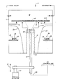
- The figure schematically depicts an example of a wafer temperature monitoring system made in accordance with our present invention, which is incorporated into a wafer annealing
system 10. Thesystem 10 includes a vacuum chamber or housing 11. Within the chamber are a plurality ofquartz support pins 12 which support asusceptor 13 about its periphery and thus leave exposed substantially all the backside of the susceptor (the bottom side in the figure). Thesusceptor 13 supports awafer 14. A combination wafer lift/infrared sensor assembly 15 includes anelevator 16 which is vertically reciprocated by anactuator mechanism 17 along a path indicated generally byarrow 18. Mounted on the upper end of theelevator 16 is aquartz wafer lifter 19 which includes a plurality of pins mounted on a support ring (not shown) for transferring thewafer 14 from thesusceptor 13 to a wafer transfer blade (not shown) and vice versa. - The process chamber 21 is isolated from the
lift mechanism 15 by abellows 22 and is isolated fromradiant lamp assembly 24 by an envelope orwindow 23. Thesusceptor 13 is uniformly heated through thewindow 23 by the circular array oflamps 25 and theassociated reflector assembly 26. Presently, the lamps are infrared and the radiant-energy-transparent window 23 is quartz. Radiant energy lamps or other heating means can be provided at the front side of the wafer as well. Our system for quickly and accurately tracking the temperature of the wafer, and thus accurately monitoring the wafer temperature, also provides fast efficient radiant heating of the wafer which closely tracks the temperature of the susceptor. - Our radiantly heated wafer annealing
system 10 includes means for measuring the temperature of thewafer 14 via thesusceptor 13, free of the backside conditions of the wafer. The temperature measurement means comprises a thermocouple mounted to or embedded in thesusceptor 13 or, preferably, an infrared sensor in the form of apyrometer 28 mounted beneath the susceptor, illustratively on thewafer lift elevator 16. Output signals from the thermocouple or pyrometer are applied via line(s) 29 to a computer control system. The closed loop control system uses the temperature data signals obtained from the susceptor to control processing of the wafer and, if desired, to provide a readout of susceptor temperature. Those of usual skill in the art will readily understand that the temperature of the wafer is obtained from that of the susceptor by measuring the actual wafer temperature over a range of susceptor temperatures so that the susceptor temperatures can be calibrated to the wafer temperatures over the range. - Our indirect measurement technique, i. e., accurately monitoring the temperature of the wafer indirectly by monitoring the temperature of the susceptor, is made possible by specially adapting the susceptor to the process. First, the
susceptor 13 is an optically opaque material having a constant emissivity over the temperature and wavelength ranges of interest. - Preferably, the susceptor is formed of graphite coated with silicon carbide or is solid silicon carbide. The associated emissivity is approximately 0.9. Those of usual skill in the art will derive other materials, compounds and combinations of materials which provide the necessary emissivity so that one can put the wafer on the front side of the susceptor and accurately monitor the temperature thereof via the backside. Secondly, the susceptor is very thin, typically 0.5 mm - 8 mm, and preferably 2 mm, to provide a very fast response time so that the susceptor quickly and closely tracks the temperature of the wafer and vice versa.
- The above features which accurately provide for monitoring of the wafer heating during processing also effect accurate heating itself. That is, our "indirect" heating of the wafer by conduction from the backside-heated, thin, constant emissivity susceptor also permits quick, accurate uniform heating of the wafer during both the fabrication of layers on the wafer (for example, the formation of silicide layers) and during annealing of such layers.
- The following is a description of one exemplary process for annealing metallization on a semiconductor wafer.
- Initially, a robot arm is used to load the wafer onto the susceptor under vacuum conditions of at least about 10⁻⁷ torr. Once the wafer is in place, the robot arm is retracted and the associated chamber opening closed to isolate the chamber from the transfer chamber. Then the chamber is back-filled to atmospheric pressure (800 torr) or to any level of vacuum, with gas or mixtures such as N₂, NH₃, Ar, forming gas, a combination of nitrogen and oxygen, a combination of argon and oxygen, etc. Once the gas conditions are established, the computer (1) controls the operation of the lamps to ramp up the temperature of the susceptor and wafer at the programmed rate to the process set point and then (2) maintains a constant susceptor temperature (or varies the temperature as required). Typically, temperatures of 300°C - 1,000°C are used for annealing metals, which can be refractory metal such as silicides, aluminum, aluminum composites such as aluminum silicon, aluminum copper, aluminum silicon copper or basically any metal used in the semiconductor industry.
- In addition to the above-described advantages, the present temperature-monitoring apparatus and process have the advantage of very little background noise. This is important at lower temperatures, where the amount of energy emitted from the wafer or susceptor is reduced and the process is sensitive to background noise. In addition, at temperatures below about 600°C, the silicon wafers are thermally transparent and the effect of front side structures is increased.
- Having thus described preferred and alternative embodiments of our present invention, those of usual skill in the art will readily devise modifications which are within the scope of the attached claims.
Claims (10)
- An apparatus (10) for measuring the temperature of a semiconductor wafer (14) independent of the backside condition of the wafer, during annealing of metallisation on the wafer, comprising:
a thin, high emissivity susceptor (13) for providing fast thermal response between the susceptor (13) and a wafer (14) supported on the front side of the susceptor (13), the susceptor (13) also having a constant emissivity;
means (12) for mounting the susceptor (13) with substantially the entire backside area thereof exposed;
means (24) for irradiating the susceptor from at least the backside thereof; and
means (28) for monitoring the temperature of the backside of the susceptor. - The apparatus of claim 1, wherein emissivity of the susceptor (13) is about 0.9 and the susceptor (13) is approximately 0.5 mm to 8 mm thick.
- The apparatus of claim 1 or 2, wherein the susceptor (13) is silicon carbide or silicon carbide-coated graphite.
- The apparatus of any of the claims 1 to 3, wherein the means for mounting the susceptor (13) comprises a plurality of fingers (12) arranged for engaging the periphery of the susceptor (13).
- The apparatus of any of the claims 1 to 4, wherein the means for monitoring the temperature of the backside of the susceptor (13) is an infrared sensor or a thermocouple (28).
- A Method for monitoring the temperature of a semiconductor wafer (14), independent of the backside conditions of the wafer, during annealing of metallization thereon, comprising:
providing a very thin, constant high emissivity susceptor (13);
supporting the susceptor (13) so as to leave substantially all of the backside of the susceptor (13) uncovered;
supporting a semiconductor wafer (14) on the front side of the susceptor (13);
radiantly heating the susceptor (13) from at least the backside thereof; and
monitoring the temperature of the wafer indirectly by monitoring the temperature of the backside of the susceptor (13). - The method of claim 6, wherein the emissivity of the susceptor (13) is about 0.9 and the susceptor (13) is approximately 0.5 mm to 8 mm thick.
- The method of claim 6 or 7, wherein the susceptor (13) is silicon carbide or silicon carbide-coated graphite.
- The method of any of the claims 6 to 8, wherein the susceptor temperature is measured using a thermocouple (28) attached to the susceptor (13) or by sensing thermal energy emitted from the backside thereof.
- The method of any of the claims 6 to 9, further comprising the step of calibrating the susceptor (13) relative to the temperature of the wafer by monitoring the temperature of the wafer (14) and the susceptor (13) over a range of temperatures and determining the difference in temperature between the wafer (14) and the susceptor (13) over the temperature range.
Applications Claiming Priority (2)
| Application Number | Priority Date | Filing Date | Title |
|---|---|---|---|
| US51071090A | 1990-04-19 | 1990-04-19 | |
| US510710 | 1990-04-19 |
Publications (3)
| Publication Number | Publication Date |
|---|---|
| EP0452777A2 true EP0452777A2 (en) | 1991-10-23 |
| EP0452777A3 EP0452777A3 (en) | 1992-09-09 |
| EP0452777B1 EP0452777B1 (en) | 1996-02-28 |
Family
ID=24031855
Family Applications (1)
| Application Number | Title | Priority Date | Filing Date |
|---|---|---|---|
| EP91105627A Expired - Lifetime EP0452777B1 (en) | 1990-04-19 | 1991-04-09 | Wafer heating and monitoring system and method of operation |
Country Status (5)
| Country | Link |
|---|---|
| EP (1) | EP0452777B1 (en) |
| JP (1) | JP2965737B2 (en) |
| KR (1) | KR100190357B1 (en) |
| DE (1) | DE69117322T2 (en) |
| ES (1) | ES2085368T3 (en) |
Cited By (2)
| Publication number | Priority date | Publication date | Assignee | Title |
|---|---|---|---|---|
| EP0675524A1 (en) * | 1994-03-31 | 1995-10-04 | Applied Materials, Inc. | Semiconductor wafer process chamber with susceptor back coating |
| WO2002084712A2 (en) * | 2001-04-17 | 2002-10-24 | Mattson Technology, Inc. | Rapid thermal processing system for integrated circuits |
Families Citing this family (1)
| Publication number | Priority date | Publication date | Assignee | Title |
|---|---|---|---|---|
| JP2939771B2 (en) * | 1990-04-09 | 1999-08-25 | アネルバ 株式会社 | Semiconductor wafer processing method and apparatus |
Citations (1)
| Publication number | Priority date | Publication date | Assignee | Title |
|---|---|---|---|---|
| US4891499A (en) * | 1988-09-09 | 1990-01-02 | Texas Instruments Incorporated | Method and apparatus for real-time wafer temperature uniformity control and slip-free heating in lamp heated single-wafer rapid thermal processing systems |
Family Cites Families (3)
| Publication number | Priority date | Publication date | Assignee | Title |
|---|---|---|---|---|
| JPH07119647B2 (en) * | 1985-07-15 | 1995-12-20 | 日本電気株式会社 | Light intensity measuring device |
| JPS62118519A (en) * | 1985-11-19 | 1987-05-29 | Mitsubishi Electric Corp | Semiconductor substrate heating device |
| US4978567A (en) * | 1988-03-31 | 1990-12-18 | Materials Technology Corporation, Subsidiary Of The Carbon/Graphite Group, Inc. | Wafer holding fixture for chemical reaction processes in rapid thermal processing equipment and method for making same |
-
1991
- 1991-04-09 ES ES91105627T patent/ES2085368T3/en not_active Expired - Lifetime
- 1991-04-09 EP EP91105627A patent/EP0452777B1/en not_active Expired - Lifetime
- 1991-04-09 DE DE69117322T patent/DE69117322T2/en not_active Expired - Fee Related
- 1991-04-17 JP JP3085477A patent/JP2965737B2/en not_active Expired - Fee Related
- 1991-04-19 KR KR1019910006259A patent/KR100190357B1/en not_active IP Right Cessation
Patent Citations (1)
| Publication number | Priority date | Publication date | Assignee | Title |
|---|---|---|---|---|
| US4891499A (en) * | 1988-09-09 | 1990-01-02 | Texas Instruments Incorporated | Method and apparatus for real-time wafer temperature uniformity control and slip-free heating in lamp heated single-wafer rapid thermal processing systems |
Cited By (6)
| Publication number | Priority date | Publication date | Assignee | Title |
|---|---|---|---|---|
| EP0675524A1 (en) * | 1994-03-31 | 1995-10-04 | Applied Materials, Inc. | Semiconductor wafer process chamber with susceptor back coating |
| US5599397A (en) * | 1994-03-31 | 1997-02-04 | Applied Materials Inc. | Semiconductor wafer process chamber with suspector back coating |
| US5725673A (en) * | 1994-03-31 | 1998-03-10 | Applied Materials Inc. | Semiconductor wafer process chamber with susceptor back coating |
| US5834059A (en) * | 1994-03-31 | 1998-11-10 | Applied Materials, Inc. | Process of depositing a layer of material on a wafer with susceptor back coating |
| WO2002084712A2 (en) * | 2001-04-17 | 2002-10-24 | Mattson Technology, Inc. | Rapid thermal processing system for integrated circuits |
| WO2002084712A3 (en) * | 2001-04-17 | 2003-03-13 | Mattson Tech Inc | Rapid thermal processing system for integrated circuits |
Also Published As
| Publication number | Publication date |
|---|---|
| KR910019167A (en) | 1991-11-30 |
| DE69117322D1 (en) | 1996-04-04 |
| KR100190357B1 (en) | 1999-06-01 |
| EP0452777B1 (en) | 1996-02-28 |
| ES2085368T3 (en) | 1996-06-01 |
| DE69117322T2 (en) | 1996-10-02 |
| JP2965737B2 (en) | 1999-10-18 |
| EP0452777A3 (en) | 1992-09-09 |
| JPH04226047A (en) | 1992-08-14 |
Similar Documents
| Publication | Publication Date | Title |
|---|---|---|
| US5098198A (en) | Wafer heating and monitor module and method of operation | |
| US5830277A (en) | Thermal processing system with supplemental resistive heater and shielded optical pyrometry | |
| US6342691B1 (en) | Apparatus and method for thermal processing of semiconductor substrates | |
| JP5173092B2 (en) | Temperature control method for processing chamber, semiconductor processing apparatus, and sensor calibration method | |
| US5937142A (en) | Multi-zone illuminator for rapid thermal processing | |
| US6172337B1 (en) | System and method for thermal processing of a semiconductor substrate | |
| US6753272B1 (en) | High-performance energy transfer method for thermal processing applications | |
| JP4033939B2 (en) | Method for calibrating a temperature measurement system | |
| US6839507B2 (en) | Black reflector plate | |
| US5707500A (en) | Vacuum processing equipment, film coating equipment and deposition method | |
| US6204484B1 (en) | System for measuring the temperature of a semiconductor wafer during thermal processing | |
| JP3023840B2 (en) | Method and apparatus for detecting misalignment of a semiconductor wafer | |
| KR20000071502A (en) | System and method for the real time determination of the in situ emissivity of a workpiece during processing | |
| US6515261B1 (en) | Enhanced lift pin | |
| EP0452777B1 (en) | Wafer heating and monitoring system and method of operation | |
| US6313443B1 (en) | Apparatus for processing material at controlled temperatures | |
| JPH06204143A (en) | Cvd equipment | |
| EP1135659B1 (en) | Apparatus and method for thermal processing of semiconductor substrates | |
| Sheets | Temperature measurement and control in a rapid thermal processor | |
| JPS6250627A (en) | Controlling method for surface temperature of substrate | |
| JP2640269B2 (en) | Processing method and processing apparatus | |
| JP2001289714A (en) | Temperature measurement method and measurement device of substrate and treating device of the substrate | |
| JP3244463B2 (en) | Vacuum processing apparatus, film forming apparatus and film forming method using the same | |
| JPH07150353A (en) | Vacuum treating device and film forming device and film forming method using the same | |
| JPH02228028A (en) | Apparatus and method for treating one or a plurality of wafers which are raw material |
Legal Events
| Date | Code | Title | Description |
|---|---|---|---|
| PUAI | Public reference made under article 153(3) epc to a published international application that has entered the european phase |
Free format text: ORIGINAL CODE: 0009012 |
|
| AK | Designated contracting states |
Kind code of ref document: A2 Designated state(s): BE DE ES FR GB IT NL |
|
| PUAL | Search report despatched |
Free format text: ORIGINAL CODE: 0009013 |
|
| AK | Designated contracting states |
Kind code of ref document: A3 Designated state(s): BE DE ES FR GB IT NL |
|
| 17P | Request for examination filed |
Effective date: 19930309 |
|
| 17Q | First examination report despatched |
Effective date: 19940609 |
|
| GRAH | Despatch of communication of intention to grant a patent |
Free format text: ORIGINAL CODE: EPIDOS IGRA |
|
| GRAA | (expected) grant |
Free format text: ORIGINAL CODE: 0009210 |
|
| AK | Designated contracting states |
Kind code of ref document: B1 Designated state(s): BE DE ES FR GB IT NL |
|
| REF | Corresponds to: |
Ref document number: 69117322 Country of ref document: DE Date of ref document: 19960404 |
|
| ET | Fr: translation filed | ||
| ITF | It: translation for a ep patent filed |
Owner name: ING. C. GREGORJ S.P.A. |
|
| REG | Reference to a national code |
Ref country code: ES Ref legal event code: FG2A Ref document number: 2085368 Country of ref document: ES Kind code of ref document: T3 |
|
| PLBE | No opposition filed within time limit |
Free format text: ORIGINAL CODE: 0009261 |
|
| STAA | Information on the status of an ep patent application or granted ep patent |
Free format text: STATUS: NO OPPOSITION FILED WITHIN TIME LIMIT |
|
| 26N | No opposition filed | ||
| NLT2 | Nl: modifications (of names), taken from the european patent patent bulletin |
Owner name: APPLIED MATERIALS, INC. |
|
| PGFP | Annual fee paid to national office [announced via postgrant information from national office to epo] |
Ref country code: FR Payment date: 19990226 Year of fee payment: 9 |
|
| PGFP | Annual fee paid to national office [announced via postgrant information from national office to epo] |
Ref country code: ES Payment date: 19990428 Year of fee payment: 9 |
|
| PG25 | Lapsed in a contracting state [announced via postgrant information from national office to epo] |
Ref country code: ES Free format text: THE PATENT HAS BEEN ANNULLED BY A DECISION OF A NATIONAL AUTHORITY Effective date: 20000410 |
|
| PG25 | Lapsed in a contracting state [announced via postgrant information from national office to epo] |
Ref country code: FR Free format text: LAPSE BECAUSE OF NON-PAYMENT OF DUE FEES Effective date: 20001229 |
|
| REG | Reference to a national code |
Ref country code: FR Ref legal event code: ST |
|
| REG | Reference to a national code |
Ref country code: GB Ref legal event code: IF02 |
|
| REG | Reference to a national code |
Ref country code: ES Ref legal event code: FD2A Effective date: 20020204 |
|
| PGFP | Annual fee paid to national office [announced via postgrant information from national office to epo] |
Ref country code: GB Payment date: 20020402 Year of fee payment: 12 |
|
| PGFP | Annual fee paid to national office [announced via postgrant information from national office to epo] |
Ref country code: DE Payment date: 20020426 Year of fee payment: 12 |
|
| PGFP | Annual fee paid to national office [announced via postgrant information from national office to epo] |
Ref country code: NL Payment date: 20020430 Year of fee payment: 12 |
|
| PGFP | Annual fee paid to national office [announced via postgrant information from national office to epo] |
Ref country code: BE Payment date: 20020524 Year of fee payment: 12 |
|
| PG25 | Lapsed in a contracting state [announced via postgrant information from national office to epo] |
Ref country code: GB Free format text: LAPSE BECAUSE OF NON-PAYMENT OF DUE FEES Effective date: 20030409 |
|
| PG25 | Lapsed in a contracting state [announced via postgrant information from national office to epo] |
Ref country code: BE Free format text: LAPSE BECAUSE OF NON-PAYMENT OF DUE FEES Effective date: 20030430 |
|
| BERE | Be: lapsed |
Owner name: *APPLIED MATERIALS INC. Effective date: 20030430 |
|
| PG25 | Lapsed in a contracting state [announced via postgrant information from national office to epo] |
Ref country code: NL Free format text: LAPSE BECAUSE OF NON-PAYMENT OF DUE FEES Effective date: 20031101 Ref country code: DE Free format text: LAPSE BECAUSE OF NON-PAYMENT OF DUE FEES Effective date: 20031101 |
|
| GBPC | Gb: european patent ceased through non-payment of renewal fee |
Effective date: 20030409 |
|
| NLV4 | Nl: lapsed or anulled due to non-payment of the annual fee |
Effective date: 20031101 |
|
| PG25 | Lapsed in a contracting state [announced via postgrant information from national office to epo] |
Ref country code: IT Free format text: LAPSE BECAUSE OF NON-PAYMENT OF DUE FEES;WARNING: LAPSES OF ITALIAN PATENTS WITH EFFECTIVE DATE BEFORE 2007 MAY HAVE OCCURRED AT ANY TIME BEFORE 2007. THE CORRECT EFFECTIVE DATE MAY BE DIFFERENT FROM THE ONE RECORDED. Effective date: 20050409 |