EP0451545B1 - Apparatus and method for adaptively compressing successive blocks of digital video - Google Patents
Apparatus and method for adaptively compressing successive blocks of digital video Download PDFInfo
- Publication number
- EP0451545B1 EP0451545B1 EP91104132A EP91104132A EP0451545B1 EP 0451545 B1 EP0451545 B1 EP 0451545B1 EP 91104132 A EP91104132 A EP 91104132A EP 91104132 A EP91104132 A EP 91104132A EP 0451545 B1 EP0451545 B1 EP 0451545B1
- Authority
- EP
- European Patent Office
- Prior art keywords
- data
- frame
- pixel data
- compressed
- signals
- Prior art date
- Legal status (The legal status is an assumption and is not a legal conclusion. Google has not performed a legal analysis and makes no representation as to the accuracy of the status listed.)
- Expired - Lifetime
Links
Images


Classifications
-
- H—ELECTRICITY
- H04—ELECTRIC COMMUNICATION TECHNIQUE
- H04N—PICTORIAL COMMUNICATION, e.g. TELEVISION
- H04N19/00—Methods or arrangements for coding, decoding, compressing or decompressing digital video signals
- H04N19/10—Methods or arrangements for coding, decoding, compressing or decompressing digital video signals using adaptive coding
- H04N19/134—Methods or arrangements for coding, decoding, compressing or decompressing digital video signals using adaptive coding characterised by the element, parameter or criterion affecting or controlling the adaptive coding
- H04N19/154—Measured or subjectively estimated visual quality after decoding, e.g. measurement of distortion
-
- H—ELECTRICITY
- H04—ELECTRIC COMMUNICATION TECHNIQUE
- H04N—PICTORIAL COMMUNICATION, e.g. TELEVISION
- H04N19/00—Methods or arrangements for coding, decoding, compressing or decompressing digital video signals
- H04N19/10—Methods or arrangements for coding, decoding, compressing or decompressing digital video signals using adaptive coding
- H04N19/102—Methods or arrangements for coding, decoding, compressing or decompressing digital video signals using adaptive coding characterised by the element, parameter or selection affected or controlled by the adaptive coding
- H04N19/103—Selection of coding mode or of prediction mode
- H04N19/112—Selection of coding mode or of prediction mode according to a given display mode, e.g. for interlaced or progressive display mode
-
- H—ELECTRICITY
- H04—ELECTRIC COMMUNICATION TECHNIQUE
- H04N—PICTORIAL COMMUNICATION, e.g. TELEVISION
- H04N19/00—Methods or arrangements for coding, decoding, compressing or decompressing digital video signals
- H04N19/10—Methods or arrangements for coding, decoding, compressing or decompressing digital video signals using adaptive coding
- H04N19/134—Methods or arrangements for coding, decoding, compressing or decompressing digital video signals using adaptive coding characterised by the element, parameter or criterion affecting or controlling the adaptive coding
- H04N19/136—Incoming video signal characteristics or properties
-
- H—ELECTRICITY
- H04—ELECTRIC COMMUNICATION TECHNIQUE
- H04N—PICTORIAL COMMUNICATION, e.g. TELEVISION
- H04N19/00—Methods or arrangements for coding, decoding, compressing or decompressing digital video signals
- H04N19/10—Methods or arrangements for coding, decoding, compressing or decompressing digital video signals using adaptive coding
- H04N19/169—Methods or arrangements for coding, decoding, compressing or decompressing digital video signals using adaptive coding characterised by the coding unit, i.e. the structural portion or semantic portion of the video signal being the object or the subject of the adaptive coding
- H04N19/17—Methods or arrangements for coding, decoding, compressing or decompressing digital video signals using adaptive coding characterised by the coding unit, i.e. the structural portion or semantic portion of the video signal being the object or the subject of the adaptive coding the unit being an image region, e.g. an object
- H04N19/176—Methods or arrangements for coding, decoding, compressing or decompressing digital video signals using adaptive coding characterised by the coding unit, i.e. the structural portion or semantic portion of the video signal being the object or the subject of the adaptive coding the unit being an image region, e.g. an object the region being a block, e.g. a macroblock
-
- H—ELECTRICITY
- H04—ELECTRIC COMMUNICATION TECHNIQUE
- H04N—PICTORIAL COMMUNICATION, e.g. TELEVISION
- H04N19/00—Methods or arrangements for coding, decoding, compressing or decompressing digital video signals
- H04N19/60—Methods or arrangements for coding, decoding, compressing or decompressing digital video signals using transform coding
- H04N19/61—Methods or arrangements for coding, decoding, compressing or decompressing digital video signals using transform coding in combination with predictive coding
-
- H—ELECTRICITY
- H04—ELECTRIC COMMUNICATION TECHNIQUE
- H04N—PICTORIAL COMMUNICATION, e.g. TELEVISION
- H04N19/00—Methods or arrangements for coding, decoding, compressing or decompressing digital video signals
- H04N19/60—Methods or arrangements for coding, decoding, compressing or decompressing digital video signals using transform coding
Definitions
- the present invention relates to the compression of digital video, and more particularly to a method and apparatus for processing digitized interlaced video signals for transmission in a compressed form.
- NTSC National Television System Committee
- SECAM Phase Alternating Line
- Digital transmission of television signals can deliver video and audio services of much higher quality than analog techniques.
- Digital transmission schemes are particularly advantageous for signals that are broadcast by satellite to cable television affiliates and/or directly to home satellite television receivers. It is expected that digital television transmitter and receiver systems will replace existing analog systems just as digital compact discs have largely replaced analog phonograph records in the audio industry.
- HDTV high definition television
- the television signals can be transmitted using a quadrature phase shift keyed (“QPSK”) modulated data stream.
- QPSK quadrature phase shift keyed
- a subscriber to the system receives the QPSK data stream via a receiver/descrambler which provides video, audio, and data to the subscriber.
- Video compression techniques have been used in the past for video teleconferencing and other specialized applications. Such systems are capable of very high compression ratios, but generally exhibit limited spatial resolution and poor motion rendition. This is usually a result of initial constraints imposed on the frame rate and on the horizontal and vertical sampling rates of the system.
- a video "frame" can be likened to one of a sequence of snapshots that together provide a moving picture. Each frame is sampled in both the horizontal and vertical direction to obtain all of the picture information contained therein.
- Video compression systems are currently under development for digital transmission of existing television signals and future high definition television signals. Such television signals are significantly more complex than teleconferencing signals and are much more difficult to compress.
- the performance of digital compression systems in television applications is highly scene dependent. In order to succeed, a compression algorithm should be able to adapt to specific conditions to increase compressibility and to mask invariable errors in a manner that will not be perceivable to a human viewer.
- US-A-4,827,340 discloses a differential pulse code modulated video coder in which an intraframe predictor and a pure interframe predictor are used for compressing the data.
- the predictors predict what picture data will be in a current television frame based on the picture data contained in a previous frame.
- the transmitted portions of a current television frame are compared to similarly situated portions of the immediately preceding television frame and the differential signal is computed between these portions of data contained in the two frames.
- the differential signal is transmitted which results in a substantial reduction in the amount of data that has to be transmitted, particularly where the picture contained in successive screens is relatively constant.
- reference US-A-4,827,340 teaches compression of a video signal, which is performed by using an interframe predictor in a first compression path and an intraframe predictor in a second compression path and the apparatus disclosed by document D1 determinos whether better compression is achieved using intraframe prediction or interframe prediction for each successive video frame.
- US-A-4,827,340 discloses a first data path for generating a first compressed video signal and a second data path for generating a second compressed video signal as well as means for evaluating the errors and means responsive to said error evaluating means.
- Video compression is further complicated with television signals since interlaced scanning is used to define a television picture.
- Each frame of a television picture comprises a plurality of horizontal lines (e.g. 525 lines in a standard NTSC television signal) which together form a picture.
- the horizontal lines are divided into even and odd fields, wherein the even lines (lines 2, 4, 6, ...) form the even field and the odd lines (lines 1, 3, 5, ...) form the odd field.
- the even and odd fields are scanned in an alternating order to interleave the even and odd lines and provide the picture information in a proper sequence.
- the use of interlaced scanning complicates the compression of television signals as compared to previous teleconferencing applications, in which the compression was not performed on an interlaced signal.
- the object of the invention is to provide a general purpose compression system for optimizing the compression of digital pixel data.
- an apparatus for processing pixel data from digitized interlaced video signals for transmission in a compressed form comprising
- a digital television system for processing pixel data from digitized interlaced video signals for transmission in a compressed form comprising:
- a method for encoding digital video signal pixel data for transmission in a compressed form comprising the steps of:
- digitized interlaced television signal can be compressed in various formats.
- each frame is separated into its two fields which are processed independently.
- the two fields are processed as a single frame by interleaving the lines of corresponding even and odd fields.
- Neither option is entirely satisfactory for video compression.
- Frame processing works better than field processing when there is little or no motion. Since each frame has twice the number of lines or samples than a field for a given picture height, there will be more correlation between samples and hence, compressibility is increased. To achieve the same accuracy as frame processing, field processing requires a higher bit rate. Thus, for equal bit rates frame processing achieves greater accuracy.
- Frame processing enjoys similar advantages over field processing if horizontally moving features have little horizontal detail or if vertically moving features have little vertical detail. In regions where there is little detail of any sort, frame processing often works better than field processing no matter how rapidly changes occur.
- the compression system combines the advantages of frame processing where there is little or no motion with the advantages of field processing in detailed moving areas.
- the inventive system permits video signals to be compressed and then reconstructed without any degradation in motion rendition and optimizes the compression of digital data by combining different compression techniques or data formats to obtain peak performance under different conditions.
- apparatus for optimizing the compression of successive blocks of digital video.
- the video blocks are compressed in a first data path to provide a first compressed signal and in a second data path to provide a second compressed signal. Errors in the first and second compressed signals are evaluated, and the compressed signal having the least error is selected for each video block. The selected signals are then combined to provide a compressed digital data stream.
- Receiver apparatus for decoding the compressed digital data stream comprises means for detecting the encoded data from each selected signal to identify whether the signal originated in the first or second data path. Means responsive to the detecting means decompresses the selected signals from the first data path in a corresponding first decompression path. Similarly, signals selected from the second data path are decompressed in a corresponding second decompression path.
- the first and second data paths can use different compression algorithms. Alternately, the same compression algorithm can be applied in each path to data that is provided to the paths in different formats. In either case, the first and second decompression paths will use decompression algorithms or data formats that correspond to those of the respective first and second data paths.
- the apparatus and method of the present invention process digitized interlaced video signals for transmission in a compressed form.
- the transmitted compressed signals are decoded at a receiver for reconstruction of the original interlaced video signals.
- a digitized interlaced video signal is divided at the transmitter into blocks of pixel data.
- the blocks are formatted into a field format and compressed to provide a first compressed video signal.
- the blocks are also formatted in a frame format and compressed to provide a second compressed video signal. Errors in the first and second compressed video signals are evaluated, and the compressed video signal having the least error is selected for each block.
- the selected signals are encoded to identify them as field formatted or frame formatted signals.
- the encoded signals are combined to provide a compressed video signal data stream for transmission.
- Motion compensation can be provided to increase the compression efficiency.
- pixel data for a current video frame contained in the digitized interlaced signal is predicted from pixel data of a previous frame.
- the predicted pixel data is subtracted from the actual pixel data for the current frame to provide an abbreviated set of pixel data for use in producing the first and second compressed video signals.
- the selected signals are encoded with motion vector data generated during the prediction step.
- the combined and coded signals are decoded.
- Field formatted signals are processed in a decoder path adapted for field processing of data.
- Frame formatted signals are processed in a decoder path adapted for frame processing of data.
- the appropriate decompressed data (field processed or frame processed) for each data block is then combined.
- Motion vector data is retrieved at the receiver from encoded selected signals representing a current video frame. Data representing a previous video frame is stored. Prediction signals are computed from the retrieved motion vector data and the stored data. The prediction signals are added to the decompressed signals, and the resultant signals are formatted to reconstruct the original digitized interlaced video signal.
- Field formatting of data at the transmitter can be accomplished by dividing the digitized interlaced video signal into even and odd blocks of pixel data corresponding to even and odd fields of a video frame.
- the even and odd blocks are then provided to a first compressing means in an alternating order defining the field format.
- Frame formatted data can be provided by grouping the blocks into corresponding odd/even block pairs, and scanning the odd and even lines of pixel data from each pair in an alternating order.
- the resultant interleaved lines of frame formatted data from successive block pairs are provided to a second compressing means.
- One compression algorithm that may be used in connection with the present invention is the Discrete Cosine Transform ("DCT"), in which case the first and second compressing means produce and quantize respective first and second arrays of transform coefficients for the pixel data.
- the error evaluating means determine the error between the quantized transform coefficients and the unquantized transform coefficients of each array.
- the error may be computed from the difference between each coefficient in an array before and after quantization, and selection between field processed and frame processed data can be made by comparing the sum of the absolute value of all the coefficient differences in the first array to the sum of the absolute value of all the coefficient differences in the second array.
- the array having the least total error is chosen for transmission.
- the error evaluating means can alternatively operate in the pixel domain, by inverse transforming the first and second arrays to recover the pixel data.
- the error for the respective field and frame processing paths is determined by comparing the pixel data recovered from each array to the original set of pixel data presented to the compression means.
- Figure 1 illustrates a single video frame 10 separated into its two component fields.
- Field 1 designated by reference numeral 12 comprises the odd lines of the video frame.
- Field 2 represented by reference numeral 14 comprises the even lines of the video frame.
- each even and odd line of the video frame is defined by an analog signal modulated with image information. Sequential lines from the even and odd fields are interleaved to provide an intelligible video picture.
- An interlaced video frame 16 is depicted in Figure 2. Odd lines 18 from Field 1 are interleaved with even lines 20 from Field 2. The even and odd lines must be interleaved in this fashion in order for a proper picture to be displayed on a television screen.
- each line of a video frame is defined by a sequence of digital data bits referred to as "pixels".
- a large amount of data is required to define each video frame of a television signal. For example, 7.4 megabits of data is required to provide one video frame at NTSC resolution. This assumes a 640 pixel by 480 line display is used with 8 bits of intensity value for each of the primary colors red, green, and blue.
- High definition television requires substantially more data to provide each video frame. In order to manage this amount of data, particularly for HDTV applications, the data must be compressed. As noted above, different data formatting and/or compression techniques can be more efficient than others at different times during the transmission of a digital data stream.
- field processing of video data in a format as shown in Figure 1 is generally preferred in detailed moving areas.
- Frame processing as depicted by the format of Figure 2, generally works better than field processing when there is little or no motion.
- the present invention provides a system that optimizes the compression of digital television data by switching between field processing and frame processing as appropriate.
- a standard digitized interlaced television signal is input at terminal 30 of the data compression apparatus shown in Figure 3.
- the process of digitizing video signals is well known in the art.
- a plurality of separate digitized signals may be provided for the various components, such as luminance and chrominance, of a video signal.
- An image defined by the interlaced video signal is decomposed by a first scan converter 32 into blocks of a size appropriate for data compression.
- Any of the various data compression techniques well known in the art can be used in accordance with the present invention.
- the most popular compression technique is known as the Discrete Cosine Transform ("DCT"). This technique is described in Chen and Pratt, "Scene Adaptive Coder", IEEE Transactions on Communications , Vol. COM-32, No. 3, March 1984. The following description explains the invention using an 8 x 8 pixel block size together with the DCT compression technique.
- scan converter 32 groups the even and odd fields of each video frame into pairs. The scan converter then alternately outputs the same block from one field and then the other. This function can be implemented using the components illustrated in the block diagram of Figure 4a.
- the digitized interlaced video signal input at terminal 30 is formatted to provide all of the lines from the odd field (Field 1) followed by all of the lines of the even field (Field 2).
- This is depicted in Figure 4b, which illustrates Field 1 (160) followed by Field 2 (162).
- the function of scan converter 32 is to divide Fields 1 and 2 into a plurality of corresponding blocks. Each block is M pixels wide by N pixels high. It takes j such blocks to cover the width of the picture and i blocks to cover the height of each field. Having established this format, scan converter 32 then outputs the blocks in alternating odd/even order, as illustrated in Figure 6.
- Figure 6 is a detailed representation of the odd and even fields 160, 162 of Figure 4b after the image has been decomposed by scan converter 32 into individual blocks of pixel data.
- Field 1 comprises odd blocks of pixel data and Field 2 comprises even blocks of pixel data.
- each 8 x 8 block contains 64 pixels.
- the first block of data output from scan converter 32 for each field pair is block 164.
- block 200 is output, followed by blocks 165, 201, 166, 202, etc.
- block 231 is output from scan converter 32, the next two fields (representing the next video frame) are processed and read out in the same manner.
- the formatting of data by scan converter 32 as described above is referred to herein as field formatted data.
- scan converter 32 can comprise a dual port RAM 70 as shown in Figure 4a.
- the data contained in a digitized interlaced video signal input at terminal 30 is loaded into RAM 70 in the order received.
- a read address is generated to enable the data to be read out of RAM 70 in the field format.
- a pixel clock signal input at terminal 72 is coupled to a pixel counter 74 that outputs a digital signal ranging from 0 to M-1. This count forms the log 2 M least significant bits of the dual port RAM read address.
- a divider 76 and horizontal block counter 78 produce a signal ranging from 0 to j-1 and forms the next log 2 j bits of the read address.
- divider circuit 80 and line counter 82 provide an output ranging from 0 to N-1, and forms the next log 2 N bits of the read address.
- Divider 84 and vertical block counter 86 provide an output ranging from 0 to i-1 to form the next log 2 i bits.
- divider 88 provides the most significant bit of the dual port RAM address in order to toggle between Field 1 and Field 2 of each video frame.
- the composite address signal input to RAM 70 requires 1 + log 2 M + log 2 j + log 2 N + log 2 i bits.
- the pixel and line counters will both require 3 bits. The number of bits required for the horizontal and vertical block counters will depend on the size of the fields.
- the read address of RAM 70 will be incremented to output the video data in a field format.
- the pixels within each block may be scanned in a different order as determined by the input requirements of the DCT algorithm or other compression device used.
- the field formatted data is output from scan converter 32 to a first compression path comprising a DCT transform coder 36 and a quantizer 38. These are conventional elements used in DCT compression, as described in the Chen and Pratt article referred to above.
- the field formatted data is also input to a second compression path comprising a second scan converter 42, a transform coder 44, and a quantizer 46. Transform coder 44 and quantizer 46 are identical to those in the first compression path.
- an optional predictor signal used for motion compensation can be subtracted by a subtraction circuit 34 prior to inputting the field formatted data to the first and second compression paths.
- a subtraction circuit 34 Prior to inputting the field formatted data to the first and second compression paths, an optional predictor signal used for motion compensation can be subtracted by a subtraction circuit 34. The motion compensation aspect of the present invention is described in more detail below.
- Scan converter 42 is used to convert the field formatted data from scan converter 32 into a frame format.
- a frame format In this format, corresponding pairs of blocks from the even and odd fields are interleaved on a line-by-line basis. Components for performing this operation are illustrated in Figure 5a.
- the frame format is illustrated in Figure 5b, which shows a pair of vertically adjacent blocks 250 comprising odd block 164 and corresponding even block 200. These are the same blocks that are illustrated in a field format in Figure 6.
- Block 164 contains 64 odd pixels 252 that represent portions of the odd lines contained in a video frame.
- Block 200 contains 64 even pixels 254 corresponding to portions of the even lines of the video frame.
- the components of Figure 5a scan the lines of pixels shown in Figure 5b in an alternating odd/even line scanning order to provide the interleaved frame formatted data.
- the field formatted data input at terminal 90 is stored by dual port RAM 92 in the order received.
- the pixel clock signal input at terminal 72 of Figure 5a is used to strobe a pixel counter 94 to provide an output signal ranging from 0 to M-1, which serves as the log 2 M least significant bits of the dual port RAM address.
- the pixel clock signal is divided by M at divider 96, and input to another divide by 2 circuit 98 for input to a line counter 100.
- the line counter outputs a digital signal ranging from 0 to N-1 which forms the next log 2 N bits of the dual port RAM address.
- the output of divide by M circuit 96 also serves as the most significant bit of the read address input of RAM 92.
- the resultant read address signal consists of 1 + log 2 N + log 2 M bits. This signal causes the data stored in RAM 92 to be read out in the frame format.
- the compressed field formatted data from the first compression path is output from quantizer 38 to a switch 39.
- the frame formatted data compressed in the second compression path is output from quantizer 46 to switch 39.
- errors in the compressed data from the two different compression paths are evaluated and the data having the least error for each odd/even block pair is selected for transmission.
- the portion of a video frame having little or no motion is compressed, it is likely that the pixel data processed in the frame format will be selected.
- the portion of the video frame being evaluated is from a detailed moving area, it is probable that the data compressed in a field format will be selected.
- Error evaluation and selection of frame processed or field processed data is achieved using hard wired logic generally designated by reference numeral 51.
- the error is determined by comparing the quantized transform coefficients to the original unquantized transform coefficients in each data path.
- the unquantized coefficients input to quantizer 38 are subtracted at 48 from the quantised coefficients output from quantizer 38.
- the unquantized coefficients input to quantizer 46 are subtracted at 50 from the quantized coefficients output from quantizer 46.
- the results are input to an error evaluation and selection circuit 52 that compares the errors in the two paths. It should be appreciated that the error evaluation and selection could alternately be implemented in software.
- the error metric used is the sum of the absolute value of all the coefficient differences.
- other metrics such as the mean squared error will also perform satisfactorily.
- the average error is evaluated over a two-block region. This is required because the frame formatted data comprises interleaved data from odd/even block pairs, as shown in Figure 5b. Comparison of field formatted data to frame formatted data must therefore occur over the two-block region.
- Quantized (Q) and unquantized ( Q ⁇ ) data from the frame format compression path are input to terminals 104 and 102 respectively of subtraction circuit 106.
- the absolute value of the difference between these signals is determined by conventional means 108, and accumulated at 110.
- the quantized and unquantized coefficients from the field format compression path are input at terminals 114, 112 respectively of subtraction circuitry 116.
- the absolute values of the differences are computed as indicated at 118, and accumulated at 120.
- the accumulated errors from the respective frame and field formatted paths are compared at a comparator 122, which provides an output signal at terminal 124 indicative of which path produced the least error for a particular pair of pixel data blocks.
- variable length coder 56 that assigns variable length codewords to represent the selected sets of quantized transform coefficients.
- An example of such a variable length coder is described in the Chen and Pratt article referred to above.
- variable length coder 56 is input to a multiplexer 58 that combines the compressed data with control data carried on data path 68.
- the control data includes a bit for encoding the selected compressed signals to identify them as field formatted or frame formatted signals. This can be the same bit used to actuate switch 39, wherein the selection of one of the compression paths is represented by "1" and the other compression path is represented by "0".
- the adaptive field/frame encoding system shown in Figure 3 can optionally be combined with motion compensation to provide additional compression efficiencies.
- Motion compensation techniques are well known in the art. Such techniques are described, for example, by Staffan Ericsson in "Fixed and Adaptive Predictors for Hybrid Predictive/Transform Coding", IEEE Transactions on Communications , Vol. COM-33, No. 12, December 1985, and Ninomiya and Ohtsuka, "A Motion-Compensated Interframe Coding Scheme for Television Pictures", IEEE Transactions on Communications , Vol. COM-30, No. 1, January 1982, both incorporated herein by reference.
- the pixel data for the current video frame is predicted by motion compensator 64 and motion estimator 66 from pixel data of a previous video frame stored in frame store 62.
- the predicted pixel data is subtracted from the actual pixel data for the current video frame at subtracter 34 to produce a set of pixel data representing a prediction error.
- the prediction error pixel data is presented to the first and second compression paths for compression and selection as described above.
- an inverse transformation to the processing stream selected by the error evaluation and selection components must be computed, followed by the inverse of the second scan converter 42 in cases where frame processing was selected.
- the inverse transform is provided by circuitry 40, and the inverse of the second scan converter is provided by circuitry 54.
- Switch 41 is actuated by the output signal from error evaluation and selection circuit 52 to couple appropriately formatted data to the motion compensation circuitry.
- the appropriate inverse transform data is added back at adder 60 to the predictor signal that was initially subtracted from the incoming video.
- the result is written into frame store 62 (e.g., a shift register or RAM) where it is delayed until it can be used as a prediction for the next frame.
- Block displacement information indicative of the location of a previous block that best matches a current block of pixel data within a predefined area, is determined by a motion estimator 66 which inputs corresponding motion vector data (X, Y) to motion compensator 64.
- the motion vector data is also input to multiplexer 58 from motion estimator 66 via path 68.
- Multiplexer 58 appends the motion vector data to the encoded video signal for use in deriving an identical prediction signal at a receiver.
- the object of motion compensation is to improve compression performance in moving areas of a video picture, it is more effective to estimate the block displacements and perform the compensation using fields instead of frames. Therefore, the displacement of each block of a given field is determined with reference to the same field of the previous frame. In some cases, better results are obtainable if the field immediately preceding the given field is chosen for the reference. In this case, an even field would be matched with an odd field, and an odd field would be matched with an even field. However, such a strategy is more difficult to implement and is not as effective when the vertical displacement is zero.
- Motion compensation is performed in the same manner regardless of whether field processing or frame processing is chosen for encoding.
- a prediction is obtained for each block of a given field by utilizing the estimated displacement vector to identify the matching block in the same field of the previous frame.
- the prediction errors from two different fields are eventually interleaved by the second scan converter 42.
- the compressed, encoded signals are output from multiplexer 58 to a transmitter (not shown).
- the transmitted signal is received by a digital television receiver, and the signals are decoded by a decoder such as that shown in Figure 8.
- the received digital signals are input at terminal 130 to a demultiplexer 132 which separates the encoded control signals from the video data signals.
- a variable length decoder 134 recovers the quantized transform coefficients. Recovered coefficients for field processed blocks are decompressed in a first decompression path comprising inverse transform coder 136 and switch 142. Recovered coefficients for frame processed blocks are decompressed in a second decompression path comprising inverse transform coder 136, inverse scan converter 140, and switch 142.
- Inverse scan converter 140 is a memory device that restores the order of pixels resulting from the use of the second scan converter 42 at the encoder back to the original scanning order.
- the control data bit identifying each pixel data block as frame processed or field processed actuates switch 142 via path 152 to apply the appropriate decompressed data from the first decompression path or second decompression path to an inverse scan converter 150.
- This inverse scan converter is a memory device that restores the reordered pixels resulting from the use of the first scan converter 32 at the encoder back to the original raster scan order.
- the output of inverse scan converter 150 is the recovered, reconstructed digitized interlaced video signal originally input to the encoder. This output signal is coupled to a video monitor for display of the video program.
- Motion compensation at the receiver is provided by frame store 146 and motion compensation circuitry 148.
- Motion vector data appended to blocks of pixel data at the encoder is retrieved by demultiplexer 132 at the receiver.
- the motion vector data is input via path 152 to motion compensation circuitry 148 which uses the data, together with data representing a previous video frame stored in frame store 146, to recompute the original prediction signals.
- the recomputed prediction signals are added to the decompressed blocks of pixel data for the current video frame at adder 144. Since the motion vector data computed by motion estimator 66 at the encoder is appended to the pixel data blocks, there is no need to provide motion estimation circuitry at the decoder and the resultant decoder system is simplified.
- the present invention provides improved data compression techniques for use in digital data transmission, and particularly for use in the transmission of digital interlaced television signals.
- the invention may be advantageously used in the transmission of HDTV signals, and provides a means for substantially reducing the amount of data that must be transmitted to define HDTV television pictures.
- a selection between frame processing and field processing based on achieving minimum error in accordance with the present invention has been found to be very effective in improving the picture quality of digitally compressed television signals. Still or slowly moving regions are rendered much more accurately than would be possible in a field processing system. Motion rendition is much better than would be possible in a frame processing system. Since the selection is made on a local basis, the system can adjust to scenes containing both moving and nonmoving features.
- block error in order to choose between frame and field processed data, block error can be evaluated in the pixel domain.
- each block of data instead of comparing transform coefficients, each block of data can be inverse transformed and then compared to the original block of pixels.
Abstract
Description
- The present invention relates to the compression of digital video, and more particularly to a method and apparatus for processing digitized interlaced video signals for transmission in a compressed form.
- Television signals are conventionally transmitted in analog form according to various standards adopted by particular countries. For example, the United States has adopted the standards of the National Television System Committee ("NTSC") while most European countries have adopted either PAL (Phase Alternating Line) or SECAM standards.
- Digital transmission of television signals can deliver video and audio services of much higher quality than analog techniques. Digital transmission schemes are particularly advantageous for signals that are broadcast by satellite to cable television affiliates and/or directly to home satellite television receivers. It is expected that digital television transmitter and receiver systems will replace existing analog systems just as digital compact discs have largely replaced analog phonograph records in the audio industry.
- A substantial amount of digital data must be transmitted in any digital television system. This is particularly true where high definition television ("HDTV") is provided. In a digital television system where signals are transmitted by satellite, the television signals can be transmitted using a quadrature phase shift keyed ("QPSK") modulated data stream. A subscriber to the system receives the QPSK data stream via a receiver/descrambler which provides video, audio, and data to the subscriber. In order to most efficiently use the available radio frequency spectrum, it is advantageous to compress the digital television signals to minimize the amount of data that must be transmitted.
- Video compression techniques have been used in the past for video teleconferencing and other specialized applications. Such systems are capable of very high compression ratios, but generally exhibit limited spatial resolution and poor motion rendition. This is usually a result of initial constraints imposed on the frame rate and on the horizontal and vertical sampling rates of the system. A video "frame" can be likened to one of a sequence of snapshots that together provide a moving picture. Each frame is sampled in both the horizontal and vertical direction to obtain all of the picture information contained therein.
- Video compression systems are currently under development for digital transmission of existing television signals and future high definition television signals. Such television signals are significantly more complex than teleconferencing signals and are much more difficult to compress. The performance of digital compression systems in television applications is highly scene dependent. In order to succeed, a compression algorithm should be able to adapt to specific conditions to increase compressibility and to mask invariable errors in a manner that will not be perceivable to a human viewer.
- Highly detailed moving objects in a television picture present the greatest challenge to a compression system. The most powerful compression systems currently available (i.e., those that achieve the greatest reduction in the amount of data necessary to define television pictures) utilize interframe processing in order to take advantage of the temporal correlation between successive frames.
- US-A-4,827,340 discloses a differential pulse code modulated video coder in which an intraframe predictor and a pure interframe predictor are used for compressing the data. The predictors predict what picture data will be in a current television frame based on the picture data contained in a previous frame. Thus, the transmitted portions of a current television frame are compared to similarly situated portions of the immediately preceding television frame and the differential signal is computed between these portions of data contained in the two frames. Instead of transmitting the whole current television frame only the differential signal is transmitted which results in a substantial reduction in the amount of data that has to be transmitted, particularly where the picture contained in successive screens is relatively constant.
- Therefore, reference US-A-4,827,340 teaches compression of a video signal, which is performed by using an interframe predictor in a first compression path and an intraframe predictor in a second compression path and the apparatus disclosed by document D1 determinos whether better compression is achieved using intraframe prediction or interframe prediction for each successive video frame.
- In summary, US-A-4,827,340 discloses a first data path for generating a first compressed video signal and a second data path for generating a second compressed video signal as well as means for evaluating the errors and means responsive to said error evaluating means.
- However, frame-to-frame correlation is reduced when there is movement. This requires more complicated processing to maintain a high degree of performance.
- Video compression is further complicated with television signals since interlaced scanning is used to define a television picture. Each frame of a television picture comprises a plurality of horizontal lines (e.g. 525 lines in a standard NTSC television signal) which together form a picture. The horizontal lines are divided into even and odd fields, wherein the even lines (
lines lines - The object of the invention is to provide a general purpose compression system for optimizing the compression of digital pixel data.
- According to the present invention this object is solved by an apparatus for processing pixel data from digitized interlaced video signals for transmission in a compressed form comprising
- a first data path for generating a first compressed video signal
- a second data path for generating a second compressed video signal
- means coupled to said first data path for evaluating errors in the first compressed video signal and coupled to said second data path for evaluating errors in the second compressed video signal; and
- means responsive to said error evaluating means for selecting the compressed video signal having the least error,
- wherein said first data path comprises means for dividing said pixel data into blocks in a field format in which each frame is separated into its odd and even field for independent processing, and means for compressing said pixel data in said field format to provide said first compressed video signal;
- said second data path comprises means for dividing said pixel data into blocks in a frame format in which the odd and even fields of a frame are processed as a single frame by interleaving the lines of corresponding odd and even fields and means for compressing said pixel data in said frame format to provide a second compressed video signal.
- Further advantageous embodiments are subject matter of
dependent claims 2 to 16. - According to the present invention the above-mentioned object is also solved by a decoder apparatus characterized in that the following means are provided:
- means for receiving compressed digital video signals transmitted in blocks of frame processed pixel data and field processed pixel data;
- means coupled to said receiving means for determining whether a particular block of data contained in a received signal was frame processed or field processed;
- first means for decoding received blocks of field processed pixel data comprising said pixel data in blocks in a field format in which each frame is separated into its odd or even field for independent processing;
- second means for decoding received blocks of frame processed pixel data comprising said pixel data in blocks in a frame format in which the odd and even fields of a frame are processed as a single frame by interleaving the line of corresponding odd and even fields; and
- means responsive to said determining means for selectively combining decoded blocks from said first and second means to recover an uncompressed video signal.
- Further advantageous embodiments are subject matter of
claims 18 to 22. - According to the present invention the object mentioned above is also solved by a digital television system for processing pixel data from digitized interlaced video signals for transmission in a compressed form comprising:
- a first data path for generating first compressed data;
- a second data path for generating second compressed data;
- means coupled to said first data path for evaluating errors in the first compressed data and coupled to said second data path for evaluating errors in the second compressed data; and
- means responsive to said error evaluating means for selecting the compressed data having the least error;
- wherein said first data path comprises means for dividing said pixel data into blocks in a field format in which each frame is separated into its odd and even field for independent processing and means for compressing said pixel data in said field format to provide said first compressed data;
- said second data path comprises means for dividing said pixel data into blocks in a frame format in which the odd and even fields of a frame are processed as a single frame by interleaving the lines of corresponding even and odd fields and means for compressing said pixel data in said frame format to provide said second compressed data;
- said means responsive to said error evaluating means are selecting the compressed data for each block having the least error;
- means for encoding the selected data for each block to identify it as field processed or frame processed data are provided; and
- means for combining the encoded selected data to provide a compressed video data stream containing interspersed blocks of field processed pixel data and frame processed pixel data for transmission by a transmitter are provided.
- Further advantageous embodiments are subject matter of
dependent claims - According to the present invention the object mentioned above is also solved by a method for encoding digital video signal pixel data for transmission in a compressed form comprising the steps of:
- generating a first compressed video signal in a first data path;
- generating a second compressed video signal in a second data path;
- evaluating errors in the first compressed video signal and evaluating errors in the second compressed video signal for selecting the compressed video signal having the least error;
- characterized in that
- for said first data path said pixel data are divided into blocks in a field format, in which each frame is separated into its odd and even field for independent processing, and said pixel data in said field format are compressed to provide said first compressed video signal; and
- for said second data path said pixel data are divided into blocks in a frame format in which the odd and even fields of a frame are processed as a single frame by interleaving the lines of corresponding even and odd fields, and said pixel data in said frame format are compressed to provide said second compressed video signal.
- Further advantageous embodiments of this method are subject matter of
dependent claims 27 to 30. - According to the present invention digitized interlaced television signal can be compressed in various formats. In one format, referred to herein as the "field format", each frame is separated into its two fields which are processed independently. In another format, referred to as the "frame format", the two fields are processed as a single frame by interleaving the lines of corresponding even and odd fields. Neither option is entirely satisfactory for video compression. Frame processing works better than field processing when there is little or no motion. Since each frame has twice the number of lines or samples than a field for a given picture height, there will be more correlation between samples and hence, compressibility is increased. To achieve the same accuracy as frame processing, field processing requires a higher bit rate. Thus, for equal bit rates frame processing achieves greater accuracy.
- Frame processing enjoys similar advantages over field processing if horizontally moving features have little horizontal detail or if vertically moving features have little vertical detail. In regions where there is little detail of any sort, frame processing often works better than field processing no matter how rapidly changes occur.
- In detailed moving areas, it is generally more efficient to compress field formatted data. In such cases, frame processing suffers from spurious high vertical frequencies introduced by the interleaving of the even and odd fields. This reduces the correlation between lines and therefore the effectiveness of the compression algorithm.
- According to the present invention the compression system combines the advantages of frame processing where there is little or no motion with the advantages of field processing in detailed moving areas. The inventive system permits video signals to be compressed and then reconstructed without any degradation in motion rendition and optimizes the compression of digital data by combining different compression techniques or data formats to obtain peak performance under different conditions.
- In accordance with the present invention, apparatus is provided for optimizing the compression of successive blocks of digital video. The video blocks are compressed in a first data path to provide a first compressed signal and in a second data path to provide a second compressed signal. Errors in the first and second compressed signals are evaluated, and the compressed signal having the least error is selected for each video block. The selected signals are then combined to provide a compressed digital data stream.
- Each selected signal is encoded with data indicative of the data path in which the signal originated. Receiver apparatus for decoding the compressed digital data stream comprises means for detecting the encoded data from each selected signal to identify whether the signal originated in the first or second data path. Means responsive to the detecting means decompresses the selected signals from the first data path in a corresponding first decompression path. Similarly, signals selected from the second data path are decompressed in a corresponding second decompression path. The first and second data paths can use different compression algorithms. Alternately, the same compression algorithm can be applied in each path to data that is provided to the paths in different formats. In either case, the first and second decompression paths will use decompression algorithms or data formats that correspond to those of the respective first and second data paths.
- In a preferred embodiment, the apparatus and method of the present invention process digitized interlaced video signals for transmission in a compressed form. The transmitted compressed signals are decoded at a receiver for reconstruction of the original interlaced video signals.
- A digitized interlaced video signal is divided at the transmitter into blocks of pixel data. The blocks are formatted into a field format and compressed to provide a first compressed video signal. The blocks are also formatted in a frame format and compressed to provide a second compressed video signal. Errors in the first and second compressed video signals are evaluated, and the compressed video signal having the least error is selected for each block. The selected signals are encoded to identify them as field formatted or frame formatted signals. The encoded signals are combined to provide a compressed video signal data stream for transmission.
- Motion compensation can be provided to increase the compression efficiency. With motion compensation, pixel data for a current video frame contained in the digitized interlaced signal is predicted from pixel data of a previous frame. The predicted pixel data is subtracted from the actual pixel data for the current frame to provide an abbreviated set of pixel data for use in producing the first and second compressed video signals. The selected signals are encoded with motion vector data generated during the prediction step.
- At a receiver, the combined and coded signals are decoded. Field formatted signals are processed in a decoder path adapted for field processing of data. Frame formatted signals are processed in a decoder path adapted for frame processing of data. The appropriate decompressed data (field processed or frame processed) for each data block is then combined.
- Motion vector data is retrieved at the receiver from encoded selected signals representing a current video frame. Data representing a previous video frame is stored. Prediction signals are computed from the retrieved motion vector data and the stored data. The prediction signals are added to the decompressed signals, and the resultant signals are formatted to reconstruct the original digitized interlaced video signal.
- Field formatting of data at the transmitter can be accomplished by dividing the digitized interlaced video signal into even and odd blocks of pixel data corresponding to even and odd fields of a video frame. The even and odd blocks are then provided to a first compressing means in an alternating order defining the field format. Frame formatted data can be provided by grouping the blocks into corresponding odd/even block pairs, and scanning the odd and even lines of pixel data from each pair in an alternating order. The resultant interleaved lines of frame formatted data from successive block pairs are provided to a second compressing means.
- One compression algorithm that may be used in connection with the present invention is the Discrete Cosine Transform ("DCT"), in which case the first and second compressing means produce and quantize respective first and second arrays of transform coefficients for the pixel data. The error evaluating means determine the error between the quantized transform coefficients and the unquantized transform coefficients of each array. The error may be computed from the difference between each coefficient in an array before and after quantization, and selection between field processed and frame processed data can be made by comparing the sum of the absolute value of all the coefficient differences in the first array to the sum of the absolute value of all the coefficient differences in the second array. The array having the least total error is chosen for transmission.
- The error evaluating means can alternatively operate in the pixel domain, by inverse transforming the first and second arrays to recover the pixel data. In this case, the error for the respective field and frame processing paths is determined by comparing the pixel data recovered from each array to the original set of pixel data presented to the compression means.
- Further features and advantages are disclosed in the drawings and the following detailed description.
- Figure 1 is an illustration depicting a video frame separated into odd and even fields for field processing of pixel data;
- Figure 2 is a diagram illustrating a video frame having interleaved even and odd lines for frame processing of pixel data;
- Figure 3 is a block diagram of data compression apparatus for use at a transmitter in accordance with the present invention;
- Figure 4a is a block diagram of circuitry that can be used to perform the function of
scan converter # 1 of Figure 3; - Figure 4b is a diagram illustrating the format of pixel data blocks output from
scan converter # 1; - Figure 5a is a block diagram of circuitry that can be used to perform the function of
scan converter # 2 of Figure 3; - Figure 5b is a diagram illustrating the format of an odd/even pair of pixel data blocks provided by
scan converter # 2; - Figure 6 is a diagram illustrating the order of individual pixel data blocks within the fields of a video frame;
- Figure 7 is a block diagram of error evaluation and selection circuitry that can be used in the apparatus of Figure 3; and
- Figure 8 is a block diagram of decoder apparatus for use at a receiver to decompress transmitted digital data and reconstruct a digitized interlaced video signal.
- Figure 1 illustrates a
single video frame 10 separated into its two component fields.Field 1 designated byreference numeral 12 comprises the odd lines of the video frame.Field 2 represented byreference numeral 14 comprises the even lines of the video frame. In prior art analog television systems, each even and odd line of the video frame is defined by an analog signal modulated with image information. Sequential lines from the even and odd fields are interleaved to provide an intelligible video picture. - An interlaced
video frame 16 is depicted in Figure 2.Odd lines 18 fromField 1 are interleaved with evenlines 20 fromField 2. The even and odd lines must be interleaved in this fashion in order for a proper picture to be displayed on a television screen. - The present invention concerns digitally transmitted data. In digital television systems, each line of a video frame is defined by a sequence of digital data bits referred to as "pixels". A large amount of data is required to define each video frame of a television signal. For example, 7.4 megabits of data is required to provide one video frame at NTSC resolution. This assumes a 640 pixel by 480 line display is used with 8 bits of intensity value for each of the primary colors red, green, and blue. High definition television requires substantially more data to provide each video frame. In order to manage this amount of data, particularly for HDTV applications, the data must be compressed. As noted above, different data formatting and/or compression techniques can be more efficient than others at different times during the transmission of a digital data stream. For example, field processing of video data in a format as shown in Figure 1 is generally preferred in detailed moving areas. Frame processing, as depicted by the format of Figure 2, generally works better than field processing when there is little or no motion. The present invention provides a system that optimizes the compression of digital television data by switching between field processing and frame processing as appropriate.
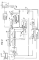
- In accordance with the present invention, a standard digitized interlaced television signal is input at
terminal 30 of the data compression apparatus shown in Figure 3. The process of digitizing video signals is well known in the art. A plurality of separate digitized signals may be provided for the various components, such as luminance and chrominance, of a video signal. When the present invention is used in conjunction with multiple luminance and chrominance components, it is most important that the luminance portion of the video signal take advantage of the adaptive field and frame processing. - An image defined by the interlaced video signal is decomposed by a
first scan converter 32 into blocks of a size appropriate for data compression. Any of the various data compression techniques well known in the art can be used in accordance with the present invention. The most popular compression technique is known as the Discrete Cosine Transform ("DCT"). This technique is described in Chen and Pratt, "Scene Adaptive Coder", IEEE Transactions on Communications, Vol. COM-32, No. 3, March 1984. The following description explains the invention using an 8 x 8 pixel block size together with the DCT compression technique. - In order to minimize complexity and memory requirements for the compression and subsequent decompression apparatus of the present invention, scan
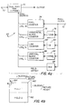
converter 32 groups the even and odd fields of each video frame into pairs. The scan converter then alternately outputs the same block from one field and then the other. This function can be implemented using the components illustrated in the block diagram of Figure 4a. - The digitized interlaced video signal input at
terminal 30 is formatted to provide all of the lines from the odd field (Field 1) followed by all of the lines of the even field (Field 2). This is depicted in Figure 4b, which illustrates Field 1 (160) followed by Field 2 (162). The function ofscan converter 32 is to divideFields scan converter 32 then outputs the blocks in alternating odd/even order, as illustrated in Figure 6. - Figure 6 is a detailed representation of the odd and even fields 160, 162 of Figure 4b after the image has been decomposed by
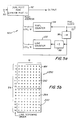
scan converter 32 into individual blocks of pixel data.Field 1 comprises odd blocks of pixel data andField 2 comprises even blocks of pixel data. In the embodiment illustrated, each 8 x 8 block contains 64 pixels. The first block of data output fromscan converter 32 for each field pair isblock 164. Next, block 200 is output, followed byblocks block 231 is output fromscan converter 32, the next two fields (representing the next video frame) are processed and read out in the same manner. The formatting of data byscan converter 32 as described above is referred to herein as field formatted data. - In order to provide field formatted data,
scan converter 32 can comprise a dual port RAM 70 as shown in Figure 4a. The data contained in a digitized interlaced video signal input atterminal 30 is loaded into RAM 70 in the order received. A read address is generated to enable the data to be read out of RAM 70 in the field format. A pixel clock signal input atterminal 72 is coupled to apixel counter 74 that outputs a digital signal ranging from 0 to M-1. This count forms the log2M least significant bits of the dual port RAM read address. Adivider 76 andhorizontal block counter 78 produce a signal ranging from 0 to j-1 and forms the next log2j bits of the read address. Another divider circuit 80 andline counter 82 provide an output ranging from 0 to N-1, and forms the next log2N bits of the read address. Divider 84 andvertical block counter 86 provide an output ranging from 0 to i-1 to form the next log2i bits. Finally,divider 88 provides the most significant bit of the dual port RAM address in order to toggle betweenField 1 andField 2 of each video frame. The composite address signal input to RAM 70 requires 1 + log2M + log2j + log2N + log2i bits. For an 8 x 8 block size, the pixel and line counters will both require 3 bits. The number of bits required for the horizontal and vertical block counters will depend on the size of the fields. - The result of the above is that the read address of RAM 70 will be incremented to output the video data in a field format. Those skilled in the art will appreciate that the pixels within each block may be scanned in a different order as determined by the input requirements of the DCT algorithm or other compression device used.
- Referring again to Figure 3, the field formatted data is output from
scan converter 32 to a first compression path comprising aDCT transform coder 36 and aquantizer 38. These are conventional elements used in DCT compression, as described in the Chen and Pratt article referred to above. The field formatted data is also input to a second compression path comprising asecond scan converter 42, atransform coder 44, and aquantizer 46.Transform coder 44 andquantizer 46 are identical to those in the first compression path. Prior to inputting the field formatted data to the first and second compression paths, an optional predictor signal used for motion compensation can be subtracted by asubtraction circuit 34. The motion compensation aspect of the present invention is described in more detail below. -
Scan converter 42 is used to convert the field formatted data fromscan converter 32 into a frame format. In this format, corresponding pairs of blocks from the even and odd fields are interleaved on a line-by-line basis. Components for performing this operation are illustrated in Figure 5a. The frame format is illustrated in Figure 5b, which shows a pair of vertically adjacent blocks 250 comprisingodd block 164 and corresponding even block 200. These are the same blocks that are illustrated in a field format in Figure 6.Block 164 contains 64odd pixels 252 that represent portions of the odd lines contained in a video frame.Block 200 contains 64 evenpixels 254 corresponding to portions of the even lines of the video frame. - The components of Figure 5a scan the lines of pixels shown in Figure 5b in an alternating odd/even line scanning order to provide the interleaved frame formatted data. The field formatted data input at
terminal 90 is stored bydual port RAM 92 in the order received. The pixel clock signal input atterminal 72 of Figure 5a is used to strobe apixel counter 94 to provide an output signal ranging from 0 to M-1, which serves as the log2M least significant bits of the dual port RAM address. The pixel clock signal is divided by M atdivider 96, and input to another divide by 2circuit 98 for input to a line counter 100. The line counter outputs a digital signal ranging from 0 to N-1 which forms the next log2N bits of the dual port RAM address. The output of divide byM circuit 96 also serves as the most significant bit of the read address input ofRAM 92. The resultant read address signal consists of 1 + log2N + log2M bits. This signal causes the data stored inRAM 92 to be read out in the frame format. - As indicated in Figure 3, the compressed field formatted data from the first compression path is output from
quantizer 38 to aswitch 39. The frame formatted data compressed in the second compression path is output fromquantizer 46 to switch 39. In accordance with the present invention, errors in the compressed data from the two different compression paths are evaluated and the data having the least error for each odd/even block pair is selected for transmission. Thus, where a portion of a video frame having little or no motion is compressed, it is likely that the pixel data processed in the frame format will be selected. Where the portion of the video frame being evaluated is from a detailed moving area, it is probable that the data compressed in a field format will be selected. - Error evaluation and selection of frame processed or field processed data is achieved using hard wired logic generally designated by
reference numeral 51. The error is determined by comparing the quantized transform coefficients to the original unquantized transform coefficients in each data path. The unquantized coefficients input toquantizer 38 are subtracted at 48 from the quantised coefficients output fromquantizer 38. Similarly, the unquantized coefficients input toquantizer 46 are subtracted at 50 from the quantized coefficients output fromquantizer 46. The results are input to an error evaluation andselection circuit 52 that compares the errors in the two paths. It should be appreciated that the error evaluation and selection could alternately be implemented in software. - In a preferred embodiment, the error metric used is the sum of the absolute value of all the coefficient differences. However, other metrics such as the mean squared error will also perform satisfactorily. In either case, the average error is evaluated over a two-block region. This is required because the frame formatted data comprises interleaved data from odd/even block pairs, as shown in Figure 5b. Comparison of field formatted data to frame formatted data must therefore occur over the two-block region.
- The error evaluation and
selection components 51 are illustrated in greater detail in Figure 7. As noted, these may be implemented in hardware or software. Quantized (Q) and unquantized (
terminals 104 and 102 respectively ofsubtraction circuit 106. The absolute value of the difference between these signals is determined by conventional means 108, and accumulated at 110. Similarly, the quantized and unquantized coefficients from the field format compression path are input atterminals 114, 112 respectively of subtraction circuitry 116. The absolute values of the differences are computed as indicated at 118, and accumulated at 120. The accumulated errors from the respective frame and field formatted paths are compared at acomparator 122, which provides an output signal atterminal 124 indicative of which path produced the least error for a particular pair of pixel data blocks. - The output signal from the error evaluation and selection components actuates switch 39 (Figure 3) to connect the compression path having the least error to downstream processing circuitry. Such circuitry includes
variable length coder 56 that assigns variable length codewords to represent the selected sets of quantized transform coefficients. An example of such a variable length coder is described in the Chen and Pratt article referred to above. - The output of
variable length coder 56 is input to amultiplexer 58 that combines the compressed data with control data carried ondata path 68. The control data includes a bit for encoding the selected compressed signals to identify them as field formatted or frame formatted signals. This can be the same bit used to actuateswitch 39, wherein the selection of one of the compression paths is represented by "1" and the other compression path is represented by "0". - The adaptive field/frame encoding system shown in Figure 3 can optionally be combined with motion compensation to provide additional compression efficiencies. Motion compensation techniques are well known in the art. Such techniques are described, for example, by Staffan Ericsson in "Fixed and Adaptive Predictors for Hybrid Predictive/Transform Coding", IEEE Transactions on Communications, Vol. COM-33, No. 12, December 1985, and Ninomiya and Ohtsuka, "A Motion-Compensated Interframe Coding Scheme for Television Pictures", IEEE Transactions on Communications, Vol. COM-30, No. 1, January 1982, both incorporated herein by reference. In order to provide motion compensation, the pixel data for the current video frame is predicted by
motion compensator 64 andmotion estimator 66 from pixel data of a previous video frame stored inframe store 62. The predicted pixel data is subtracted from the actual pixel data for the current video frame atsubtracter 34 to produce a set of pixel data representing a prediction error. The prediction error pixel data is presented to the first and second compression paths for compression and selection as described above. - In order to obtain a prediction for the next frame, an inverse transformation to the processing stream selected by the error evaluation and selection components must be computed, followed by the inverse of the
second scan converter 42 in cases where frame processing was selected. The inverse transform is provided bycircuitry 40, and the inverse of the second scan converter is provided bycircuitry 54.Switch 41 is actuated by the output signal from error evaluation andselection circuit 52 to couple appropriately formatted data to the motion compensation circuitry. The appropriate inverse transform data is added back atadder 60 to the predictor signal that was initially subtracted from the incoming video. The result is written into frame store 62 (e.g., a shift register or RAM) where it is delayed until it can be used as a prediction for the next frame. - Block displacement information, indicative of the location of a previous block that best matches a current block of pixel data within a predefined area, is determined by a
motion estimator 66 which inputs corresponding motion vector data (X, Y) tomotion compensator 64. The motion vector data is also input to multiplexer 58 frommotion estimator 66 viapath 68.Multiplexer 58 appends the motion vector data to the encoded video signal for use in deriving an identical prediction signal at a receiver. - Since the object of motion compensation is to improve compression performance in moving areas of a video picture, it is more effective to estimate the block displacements and perform the compensation using fields instead of frames. Therefore, the displacement of each block of a given field is determined with reference to the same field of the previous frame. In some cases, better results are obtainable if the field immediately preceding the given field is chosen for the reference. In this case, an even field would be matched with an odd field, and an odd field would be matched with an even field. However, such a strategy is more difficult to implement and is not as effective when the vertical displacement is zero.
- Motion compensation is performed in the same manner regardless of whether field processing or frame processing is chosen for encoding. A prediction is obtained for each block of a given field by utilizing the estimated displacement vector to identify the matching block in the same field of the previous frame. In cases where frame processing is chosen for encoding, the prediction errors from two different fields are eventually interleaved by the
second scan converter 42. - The compressed, encoded signals are output from
multiplexer 58 to a transmitter (not shown). The transmitted signal is received by a digital television receiver, and the signals are decoded by a decoder such as that shown in Figure 8. The received digital signals are input atterminal 130 to a demultiplexer 132 which separates the encoded control signals from the video data signals. A variable length decoder 134 recovers the quantized transform coefficients. Recovered coefficients for field processed blocks are decompressed in a first decompression path comprisinginverse transform coder 136 andswitch 142. Recovered coefficients for frame processed blocks are decompressed in a second decompression path comprisinginverse transform coder 136,inverse scan converter 140, andswitch 142.Inverse scan converter 140 is a memory device that restores the order of pixels resulting from the use of thesecond scan converter 42 at the encoder back to the original scanning order. The control data bit identifying each pixel data block as frame processed or field processed actuates switch 142 via path 152 to apply the appropriate decompressed data from the first decompression path or second decompression path to aninverse scan converter 150. This inverse scan converter is a memory device that restores the reordered pixels resulting from the use of thefirst scan converter 32 at the encoder back to the original raster scan order. The output ofinverse scan converter 150 is the recovered, reconstructed digitized interlaced video signal originally input to the encoder. This output signal is coupled to a video monitor for display of the video program. - Motion compensation at the receiver is provided by frame store 146 and motion compensation circuitry 148. Motion vector data appended to blocks of pixel data at the encoder is retrieved by demultiplexer 132 at the receiver. The motion vector data is input via path 152 to motion compensation circuitry 148 which uses the data, together with data representing a previous video frame stored in frame store 146, to recompute the original prediction signals. The recomputed prediction signals are added to the decompressed blocks of pixel data for the current video frame at adder 144. Since the motion vector data computed by
motion estimator 66 at the encoder is appended to the pixel data blocks, there is no need to provide motion estimation circuitry at the decoder and the resultant decoder system is simplified. - It will now be appreciated that the present invention provides improved data compression techniques for use in digital data transmission, and particularly for use in the transmission of digital interlaced television signals. The invention may be advantageously used in the transmission of HDTV signals, and provides a means for substantially reducing the amount of data that must be transmitted to define HDTV television pictures.
- A selection between frame processing and field processing based on achieving minimum error in accordance with the present invention has been found to be very effective in improving the picture quality of digitally compressed television signals. Still or slowly moving regions are rendered much more accurately than would be possible in a field processing system. Motion rendition is much better than would be possible in a frame processing system. Since the selection is made on a local basis, the system can adjust to scenes containing both moving and nonmoving features.
- In a modification and adaptation of the inventive system described for example, in order to choose between frame and field processed data, block error can be evaluated in the pixel domain. In this instance, instead of comparing transform coefficients, each block of data can be inverse transformed and then compared to the original block of pixels.
Claims (30)
- Apparatus for processing pixel data from digitized interlaced video signals for transmission in a compressed form comprisinga first data path (32, 36, 38) for generating a first compressed video signala second data path (42, 44, 46) for generating a second compressed video signalmeans (51) coupled to said first data path for evaluating errors in the first compressed video signal and coupled to said second data path for evaluating errors in the second compressed video signal; andmeans (52, 39) responsive to said error evaluating means for selecting the compressed video signal having the least error,characterized in thatsaid first data path comprises means (32) for dividing said pixel data into blocks in a field format in which each frame (10) is separated into its odd (lines 12) and even field (lines 14) for independent processing, and means (36, 38) for compressing said pixel data in said field format to provide said first compressed video signal;said second data path comprises means (42) for dividing said pixel data into blocks in a frame format in which the odd (lines 18) and even fields (lines 20) of a frame are processed as a single frame by interleaving the lines (18, 20) of corresponding odd (lines 18) and even fields (lines 20) and means (44, 46) for compressing said pixel data in said frame format to provide a second compressed video signal.
- Apparatus in accordance with claim 1 wherein:successive sets of pixel data are sequentially compressed and evaluated; andsaid selecting means (51) select the compressed video signal having the least error for each particular set.
- Apparatus in accordance with claim 1 or 2 further comprising:
means for encoding (58) the selected signals to identify them as field formatted or frame formatted signals. - Apparatus in accordance with claim 3 further comprising:
means for combining (58) the encoded selected signals to provide a compressed video signal data stream for transmission. - Apparatus in accordance with any of claims 1 to 4 further comprising:means (32) for dividing a digitized interlaced video signal into even and odd blocks of pixel data corresponding to even and odd fields of a video frame; andmeans (32) for presenting said even and odd blocks to said first compressing means (36, 38) in an alternating order defining said field format.
- Apparatus in accordance with claim 5 further comprising:means (42) for grouping said blocks into corresponding odd/even block pairs and scanning the odd and even lines of each pair in an alternating order to provide interleaved lines of pixel data; andmeans (42) for presenting the interleaved lines of pixel data from successive block pairs to said second compressing means (44, 46).
- Apparatus in accordance with any of claims 1-6 wherein said sets each comprise two vertically adjacent blocks of pixel data from a video frame.
- Apparatus in accordance with claim 1 wherein:said first and second compressing means (36, 38; 44, 46) produce and quantize respective first and second arrays of transform coefficients for the set of pixel data; andsaid error evaluating means (51) determine the error between the quantized transform coefficients and the unquantized transform coefficients of each array.
- Apparatus in accordance with claim 8 wherein:said error evaluating means (51) determine said error by computing the difference between each coefficient in an array before and after quantization; andsaid selecting means (52) compare the average error of all the coefficient differences in said first array to the average error of all the coefficient differences in said second array to identify the array having the least total error.
- Apparatus in accordance with claim 1 wherein:said first compressing means (36, 38) produce a first array of transform coefficients for said set of pixel data;said second compressing means (44, 46) produce a second array of transform coefficients for said set of pixel data; andsaid error evaluating means (51) comprise:means for inverse transforming said first and second arrays to recover the pixel data, andmeans for determining the error between the pixel data recovered from each array and the original set of pixel data presented to the first and second compressing means.
- Apparatus in accordance with claim 1 further comprising:means (30) for receiving a digitized interlaced video signal containing pixel data defining a sequence of video frames;means for predicting (62, 64, 66) the pixel data for a current video frame from pixel data of a previous video frame;means for subtracting (34) the predicted pixel data from the actual pixel data for the current video frame to produce a set of pixel data representing a prediction error;means for presenting (32, 34, 90) the prediction error pixel data to said first compressing means in a field format; andmeans for presenting (34, 90, 42) the prediction error pixel data to said second compressing means in a frame format.
- Apparatus in accordance with claim 11 further comprising:
means for dividing (32) each video frame of the digitized interlaced video signal into successive blocks of pixel data for processing on a block-by-block basis by said predicting, subtracting and presenting means. - Apparatus in accordance with claim 11 or 12 further comprising:
means for encoding (58) the selected signals with motion vector data generated by said predicting means. - Apparatus in accordance with any of claims 11 to 13 further comprising:
means for encoding (58) the selected signals to identify them as field formatted or frame formatted signals. - Apparatus in accordance with claim 14 further comprising:
means for combining (58) the encoded selected signals to provide a compressed video signal data stream for transmission. - A receiver for decoding the compressed digital data stream from the apparatus of one of claims 1 to 15 comprising:means for detecting (132) the encoding data from each selected signal to identify whether the signal originated in the first data path or the second data path; andmeans for responsive to said detecting means (142) for processing the selected signals from the first data path in a corresponding first decompression path (134, 136) and for processing the selected signals from the second data path in a corresponding second decompression path (134, 136, 140).
- Decoder apparatus characterized in that the following means are provided:means (130) for receiving compressed digital video signals transmitted in blocks of frame processed pixel data and field processed pixel data;means (132) coupled to said receiving means for determining whether a particular block of data contained in a received signal was frame processed or field processed;first means (134, 136) for decoding received blocks of field processed pixel data, said field processed pixel data comprising said pixel data in blocks in a field format in which each frame (10) is separated into its odd (lines 12) or even field (lines 14) for independent processingsecond means (134, 136, 140) for decoding received blocks of frame processed pixel data, said frame processed pixel data comprising said pixel data in blocks in a frame format in which the odd (lines 18) and even fields (lines 20) of a frame are processed as a single frame (10) by interleaving the lines (18, 20) of corresponding odd (lines 18) and even fields (lines 20); andmeans (142) responsive to said determining means for selectively combining decoded blocks from said first and second means to recover an uncompressed video signal.
- Apparatus in accordance with claim 17 further comprising means (150) for converting the recovered signal to a digitized interlaced video signal.
- Apparatus in accordance with claim 17 or 18 wherein said determining means (132) comprises means for reading field and frame processing identification data appended to said blocks.
- Apparatus in accordance with any claims 17 to 19 wherein said blocks comprise arrays of transform coefficients, and the first and second means comprise means for inverse transforming (136) said coefficients.
- Apparatus in accordance with claim 20 wherein the inverse transforming means are shared by said first and second means.
- Apparatus in accordance with any of claims 17 to 21 further comprising:means (132) for retrieving motion vector data appended to received blocks of pixel data representing a current video frame;means for storing (146) data representing a previous video frame;means for computing prediction signals (148) from the retrieved motion vector data and the stored data; andmeans for adding (144) said prediction signals to the received blocks for the current video frame.
- A digital television system for processing pixel data from digitized interlaced video signals for transmission in a compressed form comprising:a first data path (32, 36, 38) for generating first compressed data;a second data path (42, 44, 46) for generating second compressed data;means (51) coupled to said first data path for evaluating errors in the first compressed data and coupled to said second data path for evaluating errors in the second compressed data; andmeans (52, 39) responsive to said error evaluating means for selecting the compressed data having the least error;characterized in thatsaid first data path comprises means (32) for dividing said pixel data into blocks in a field format in which each frame (10) is separated into its odd (lines 12) and even fields (lines 14) for independent processing and means (36, 38) for compressing said pixel data in said field format to provide said first compressed data;said second data path comprises means (42) for dividing said pixel data into blocks in a frame format in which the odd (lines 18) and even fields (lines 20) of a frame are processed as a single frame (16) by interleaving the lines (18, 20) of corresponding odd and even fields and means (44, 46) for compressing said pixel data in said frame format to provide said second compressed data;said means (52, 39) responsive to said error evaluating means are selecting the compressed data for each block having the least error;means (58) for encoding the selected data for each block to identify it as field processed or frame processed data are provided; andmeans (58) for combining the encoded selected data to provide a compressed video data stream containing interspersed blocks of field processed pixel data and frame processed pixel data for transmission by a transmitter are provided.
- The system of claim 23 further comprising:receiver means for receiving a compressed video data stream from said transmitter;means operatively associated with said receiver means (132) for decoding the encoded data in said data stream to identify field processed blocks and frame processed blocks;first means (134, 136) for processing received blocks of field processed data;second means (134, 136, 140) for processing received blocks of frame processed data; andmeans (142) responsive to said decoding means (132) for selectively combining blocks from said first and second processing means to recover an uncompressed digitized interlaced video signal.
- The system of claim 24 wherein said digitized interlaced video signal defines a sequence of video frames, said system further comprising:means for predicting (62, 64, 66) the pixel data for a current video frame from pixel data of a previous video frame;means for subtracting (34) the predicted pixel data from the actual pixel data for the current video frame to produce a set of pixel data representing a prediction error;means for presenting (90) the prediction error pixel data to said first data compression means (36, 38) as field formatted blocks;means for presenting (90, 42) the prediction error pixel data to said second data compression means as frame formatted blocks;means (66) operatively associated with said predicting means for generating motion vector data for the current video frame;means (58) operatively associated with said generating means for encoding the selected data for each block with corresponding motion vector data;means (132) operatively associated with said receiver means for retrieving the motion vector data from each block of a current video frame;means (146) operatively associated with said receiver for storing data representing a previous video frame;means (148) for computing prediction signals from the retrieved motion vector data and the stored data; andmeans for adding (144) said prediction signals to the received blocks for the current video frame.
- A method for encoding digital video signal pixel data for transmission in a compressed form comprising the steps of:generating a first compressed video signal in a first data path;generating a second compressed video signal in a second data path;evaluating errors in the first compressed video signal and evaluating errors in the second compressed video signal for selecting the compressed video signal having the least errors;characterized in thatfor said first data path said pixel data are divided into blocks in a field format, in which each frame (10) is separated into its odd (lines 12) and even field (lines 14) for independent processing, and said pixel data in said field format are compressed to provide said first compressed video signal; andfor said second data path said pixel data are divided into blocks in a frame format in which the odd (lines 18) and even fields (lines 20) of a frame are processed as a single frame (16) by interleaving the lines (18, 20) of corresponding odd and even fields, and said pixel data in said frame format are compressed to provide said second compressed video signal.
- A method in accordance with claim 26 comprising the steps ofselecting, for each block, the compressed video signal having the least error;encoding the selected signals to identify them as field formatted or frame formatted signals; andcombining the encoded signals.
- A method in accordance with claim 27 comprising the further steps of:predicting the pixel data for a current video frame contained in said digital video signal from pixel data of a previous frame;subtracting said predicted pixel data from the actual pixel data for the current frame to provide an abbreviated set of pixel data for use in producing said first and second compressed video signals; andencoding the selected signals with motion vector data generated during said prediction step.
- A method for decoding the combined encoded signals produced by the method of claim 28, comprising the steps of:decompressing field formatted signals in a decompression path adapted for field processing of data;decompressing frame formatted signals in a decompression path adapted for frame processing of data;retrieving the motion vector data from encoded selected signals representing a current video frame;storing data representing a previous video frame;obtaining prediction signals from the stored data using the retrieved motion vector data;adding said prediction signals to the decompressed signals; andcombining the decompressed signals to recover the digital video signal.
- A method for decoding the combined encoded signals produced by the method of any of claims 26 to 28, comprising the steps of:decompressing field formatted signals in a decompression path adapted for field processing of data;decompressing frame formatted signals in a decompression path adapted for frame processing of data; andcombining the decompressed signals to recover the digital video signal.
Applications Claiming Priority (2)
| Application Number | Priority Date | Filing Date | Title |
|---|---|---|---|
| US07/507,258 US5091782A (en) | 1990-04-09 | 1990-04-09 | Apparatus and method for adaptively compressing successive blocks of digital video |
| US507258 | 1990-04-09 |
Publications (2)
| Publication Number | Publication Date |
|---|---|
| EP0451545A1 EP0451545A1 (en) | 1991-10-16 |
| EP0451545B1 true EP0451545B1 (en) | 1996-06-12 |
Family
ID=24017897
Family Applications (1)
| Application Number | Title | Priority Date | Filing Date |
|---|---|---|---|
| EP91104132A Expired - Lifetime EP0451545B1 (en) | 1990-04-09 | 1991-03-18 | Apparatus and method for adaptively compressing successive blocks of digital video |
Country Status (14)
| Country | Link |
|---|---|
| US (1) | US5091782A (en) |
| EP (1) | EP0451545B1 (en) |
| JP (1) | JP2795420B2 (en) |
| KR (1) | KR100188423B1 (en) |
| AT (1) | ATE139402T1 (en) |
| AU (1) | AU627684B2 (en) |
| CA (1) | CA2038043C (en) |
| DE (1) | DE69120139T2 (en) |
| DK (1) | DK0451545T3 (en) |
| ES (1) | ES2088440T3 (en) |
| GR (1) | GR3020736T3 (en) |
| HK (1) | HK1008410A1 (en) |
| IE (1) | IE74861B1 (en) |
| NO (2) | NO178419C (en) |
Families Citing this family (239)
| Publication number | Priority date | Publication date | Assignee | Title |
|---|---|---|---|---|
| US5768517A (en) * | 1988-10-17 | 1998-06-16 | Kassatly; Samuel Anthony | Paperless publication distribution and retrieval system |
| US5767913A (en) * | 1988-10-17 | 1998-06-16 | Kassatly; Lord Samuel Anthony | Mapping system for producing event identifying codes |
| US5691777A (en) * | 1988-10-17 | 1997-11-25 | Kassatly; Lord Samuel Anthony | Method and apparatus for simultaneous compression of video, audio and data signals |
| US5508733A (en) * | 1988-10-17 | 1996-04-16 | Kassatly; L. Samuel A. | Method and apparatus for selectively receiving and storing a plurality of video signals |
| US5790177A (en) * | 1988-10-17 | 1998-08-04 | Kassatly; Samuel Anthony | Digital signal recording/reproduction apparatus and method |
| US5379351A (en) * | 1992-02-19 | 1995-01-03 | Integrated Information Technology, Inc. | Video compression/decompression processing and processors |
| DE3917567A1 (en) * | 1989-05-30 | 1990-12-06 | Siemens Ag | METHOD FOR DETERMINING A DECISION RESULT FOR A HALF / FULL FRAME DATA COMPRESSION METHOD |
| US5481737A (en) * | 1989-05-30 | 1996-01-02 | Fujitsu Limited | Image data quantizing circuit with a memory for storing unquantized and quantized image data |
| US5068724A (en) * | 1990-06-15 | 1991-11-26 | General Instrument Corporation | Adaptive motion compensation for digital television |
| US5227875A (en) * | 1990-08-20 | 1993-07-13 | Kabushiki Kaisha Toshiba | System for transmitting encoded image data with quick image expansion and contraction |
| US5253275A (en) * | 1991-01-07 | 1993-10-12 | H. Lee Browne | Audio and video transmission and receiving system |
| NL9100234A (en) | 1991-02-11 | 1992-09-01 | Philips Nv | CODING CIRCUIT FOR TRANSFORMING CODING OF AN IMAGE SIGNAL AND DECODING CIRCUIT FOR DECODING THEREOF. |
| US5268755A (en) * | 1991-02-21 | 1993-12-07 | Matsushita Electric Industrial Co., Ltd. | Orthogonal transformation encoder |
| US5388167A (en) * | 1991-03-12 | 1995-02-07 | Hitachi, Ltd. | Document image processing system and document image processing method |
| US5428693A (en) * | 1991-04-12 | 1995-06-27 | Mitsubishi Denki Kabushiki Kaisha | Motion compensation predicting coding method and apparatus |
| USRE37858E1 (en) * | 1991-04-12 | 2002-09-24 | Mitsubishi Denki Kabushiki Kaisha | Motion compensation predicting encoding method and apparatus |
| US5457780A (en) * | 1991-04-17 | 1995-10-10 | Shaw; Venson M. | System for producing a video-instruction set utilizing a real-time frame differential bit map and microblock subimages |
| US5347309A (en) * | 1991-04-25 | 1994-09-13 | Matsushita Electric Industrial Co., Ltd. | Image coding method and apparatus |
| DE4113505A1 (en) * | 1991-04-25 | 1992-10-29 | Thomson Brandt Gmbh | METHOD FOR IMAGE SIGNAL CODING |
| JP3338460B2 (en) * | 1991-05-09 | 2002-10-28 | ソニー株式会社 | Video signal encoding device and video signal encoding method |
| EP0514663A3 (en) * | 1991-05-24 | 1993-07-14 | International Business Machines Corporation | An apparatus and method for motion video encoding employing an adaptive quantizer |
| US5784107A (en) * | 1991-06-17 | 1998-07-21 | Matsushita Electric Industrial Co., Ltd. | Method and apparatus for picture coding and method and apparatus for picture decoding |
| US5233629A (en) * | 1991-07-26 | 1993-08-03 | General Instrument Corporation | Method and apparatus for communicating digital data using trellis coded qam |
| US5539466A (en) * | 1991-07-30 | 1996-07-23 | Sony Corporation | Efficient coding apparatus for picture signal and decoding apparatus therefor |
| TW199257B (en) * | 1991-07-30 | 1993-02-01 | Sony Co Ltd | |
| US5983004A (en) * | 1991-09-20 | 1999-11-09 | Shaw; Venson M. | Computer, memory, telephone, communications, and transportation system and methods |
| US5706290A (en) * | 1994-12-15 | 1998-01-06 | Shaw; Venson | Method and apparatus including system architecture for multimedia communication |
| US6424989B1 (en) * | 1991-09-20 | 2002-07-23 | Venson M. Shaw | Object-oriented transaction computing system |
| WO1994009595A1 (en) * | 1991-09-20 | 1994-04-28 | Shaw Venson M | Method and apparatus including system architecture for multimedia communications |
| JPH0595540A (en) * | 1991-09-30 | 1993-04-16 | Sony Corp | Dynamic picture encoder |
| JP2991833B2 (en) * | 1991-10-11 | 1999-12-20 | 松下電器産業株式会社 | Interlace scanning digital video signal encoding apparatus and method |
| JP2586260B2 (en) * | 1991-10-22 | 1997-02-26 | 三菱電機株式会社 | Adaptive blocking image coding device |
| US5235419A (en) * | 1991-10-24 | 1993-08-10 | General Instrument Corporation | Adaptive motion compensation using a plurality of motion compensators |
| JP2925046B2 (en) * | 1991-10-31 | 1999-07-26 | ケイディディ株式会社 | Motion compensation prediction method for moving images |
| US5227878A (en) * | 1991-11-15 | 1993-07-13 | At&T Bell Laboratories | Adaptive coding and decoding of frames and fields of video |
| US5510840A (en) * | 1991-12-27 | 1996-04-23 | Sony Corporation | Methods and devices for encoding and decoding frame signals and recording medium therefor |
| EP0573665B1 (en) * | 1991-12-27 | 1998-09-30 | Sony Corporation | Image data coding method, image data decoding method, image data coding device, image data decoding device |
| KR930015851A (en) * | 1991-12-31 | 1993-07-24 | 배순훈 | Image compression transmission device with field and frame selection |
| DE69333896T2 (en) * | 1992-01-29 | 2006-07-27 | Mitsubishi Denki K.K. | Apparatus and method for recording / reproducing video information |
| US6870884B1 (en) * | 1992-01-29 | 2005-03-22 | Mitsubishi Denki Kabushiki Kaisha | High-efficiency encoder and video information recording/reproducing apparatus |
| US6965644B2 (en) * | 1992-02-19 | 2005-11-15 | 8×8, Inc. | Programmable architecture and methods for motion estimation |
| US5500923A (en) * | 1992-02-28 | 1996-03-19 | Canon Kabushiki Kaisha | Image processing apparatus utilizing the JBIG method, having a compression/expansion circuit to manage memory more effectively |
| EP0631444B1 (en) * | 1992-03-03 | 1998-12-23 | Kabushiki Kaisha Toshiba | Time-varying image encoder |
| US5436665A (en) * | 1992-03-03 | 1995-07-25 | Kabushiki Kaisha Toshiba | Motion picture coding apparatus |
| JPH05298419A (en) * | 1992-04-20 | 1993-11-12 | Ricoh Co Ltd | Picture filing device |
| EP0574167B1 (en) * | 1992-06-09 | 2007-02-28 | Canon Kabushiki Kaisha | Coding apparatus |
| US5450544A (en) * | 1992-06-19 | 1995-09-12 | Intel Corporation | Method and apparatus for data buffering and queue management of digital motion video signals |
| TW241416B (en) * | 1992-06-29 | 1995-02-21 | Sony Co Ltd | |
| US5666461A (en) * | 1992-06-29 | 1997-09-09 | Sony Corporation | High efficiency encoding and decoding of picture signals and recording medium containing same |
| US6226327B1 (en) | 1992-06-29 | 2001-05-01 | Sony Corporation | Video coding method and apparatus which select between frame-based and field-based predictive modes |
| US5784631A (en) * | 1992-06-30 | 1998-07-21 | Discovision Associates | Huffman decoder |
| JPH0662389A (en) * | 1992-08-04 | 1994-03-04 | Matsushita Electric Ind Co Ltd | Video signal encoder |
| KR970005831B1 (en) * | 1992-09-09 | 1997-04-21 | 대우전자 주식회사 | Image coder using adaptive frame/field change coding method |
| KR0134504B1 (en) * | 1992-09-09 | 1998-04-23 | 배순훈 | Image coder with adaptive frequency converter |
| US7298851B1 (en) * | 1992-12-09 | 2007-11-20 | Discovery Communications, Inc. | Electronic book security and copyright protection system |
| US5600573A (en) * | 1992-12-09 | 1997-02-04 | Discovery Communications, Inc. | Operations center with video storage for a television program packaging and delivery system |
| US7849393B1 (en) | 1992-12-09 | 2010-12-07 | Discovery Communications, Inc. | Electronic book connection to world watch live |
| US9286294B2 (en) | 1992-12-09 | 2016-03-15 | Comcast Ip Holdings I, Llc | Video and digital multimedia aggregator content suggestion engine |
| US5986690A (en) * | 1992-12-09 | 1999-11-16 | Discovery Communications, Inc. | Electronic book selection and delivery system |
| US7269841B1 (en) | 1992-12-09 | 2007-09-11 | Sedna Patent Services, Llc | Digital cable headend for cable television delivery system |
| US7835989B1 (en) | 1992-12-09 | 2010-11-16 | Discovery Communications, Inc. | Electronic book alternative delivery systems |
| US8073695B1 (en) | 1992-12-09 | 2011-12-06 | Adrea, LLC | Electronic book with voice emulation features |
| US6181335B1 (en) | 1992-12-09 | 2001-01-30 | Discovery Communications, Inc. | Card for a set top terminal |
| US7401286B1 (en) * | 1993-12-02 | 2008-07-15 | Discovery Communications, Inc. | Electronic book electronic links |
| US7336788B1 (en) * | 1992-12-09 | 2008-02-26 | Discovery Communicatoins Inc. | Electronic book secure communication with home subsystem |
| US7509270B1 (en) * | 1992-12-09 | 2009-03-24 | Discovery Communications, Inc. | Electronic Book having electronic commerce features |
| US7168084B1 (en) | 1992-12-09 | 2007-01-23 | Sedna Patent Services, Llc | Method and apparatus for targeting virtual objects |
| US5659350A (en) | 1992-12-09 | 1997-08-19 | Discovery Communications, Inc. | Operations center for a television program packaging and delivery system |
| US6463585B1 (en) | 1992-12-09 | 2002-10-08 | Discovery Communications, Inc. | Targeted advertisement using television delivery systems |
| US7073187B1 (en) | 1992-12-09 | 2006-07-04 | Sedna Patent Services, Llc | Menu-driven television program access system and method |
| ES2152712T3 (en) | 1992-12-09 | 2001-02-01 | Discovery Communicat Inc | DISTRIBUTION SYSTEM OF TELEVISION PROGRAMS. |
| US5600364A (en) | 1992-12-09 | 1997-02-04 | Discovery Communications, Inc. | Network controller for cable television delivery systems |
| DE69328346T2 (en) * | 1992-12-22 | 2000-10-12 | Koninkl Philips Electronics Nv | Device for coding digital long-distance image signals |
| US5376968A (en) * | 1993-03-11 | 1994-12-27 | General Instrument Corporation | Adaptive compression of digital video data using different modes such as PCM and DPCM |
| US5915040A (en) * | 1993-03-29 | 1999-06-22 | Canon Kabushiki Kaisha | Image processing apparatus |
| US5617143A (en) * | 1993-03-29 | 1997-04-01 | Canon Kabushiki Kaisha | Movement detection device and encoding apparatus using the same |
| US6078615A (en) * | 1993-03-31 | 2000-06-20 | Canon Kabushiki Kaisha | Encoding/decoding apparatus which performs an inverse orthogonal transformation on decoded data |
| TW301098B (en) * | 1993-03-31 | 1997-03-21 | Sony Co Ltd | |
| JP3163837B2 (en) * | 1993-04-16 | 2001-05-08 | ソニー株式会社 | Digital video signal encoding device |
| US5555193A (en) * | 1993-05-25 | 1996-09-10 | Kabushiki Kaisha Toshiba | Video compression system with editing flag |
| KR100317868B1 (en) * | 1993-07-12 | 2002-04-24 | 이데이 노부유끼 | Image Decoding Method and Apparatus, Image Encoding Method and Apparatus |
| US5610657A (en) * | 1993-09-14 | 1997-03-11 | Envistech Inc. | Video compression using an iterative error data coding method |
| JPH07123447A (en) * | 1993-10-22 | 1995-05-12 | Sony Corp | Method and device for recording image signal, method and device for reproducing image signal, method and device for encoding image signal, method and device for decoding image signal and image signal recording medium |
| US6058473A (en) * | 1993-11-30 | 2000-05-02 | Texas Instruments Incorporated | Memory store from a register pair conditional upon a selected status bit |
| US7865567B1 (en) | 1993-12-02 | 2011-01-04 | Discovery Patent Holdings, Llc | Virtual on-demand electronic book |
| US9053640B1 (en) | 1993-12-02 | 2015-06-09 | Adrea, LLC | Interactive electronic book |
| US7861166B1 (en) | 1993-12-02 | 2010-12-28 | Discovery Patent Holding, Llc | Resizing document pages to fit available hardware screens |
| US5828786A (en) * | 1993-12-02 | 1998-10-27 | General Instrument Corporation | Analyzer and methods for detecting and processing video data types in a video data stream |
| US8095949B1 (en) | 1993-12-02 | 2012-01-10 | Adrea, LLC | Electronic book with restricted access features |
| US5438374A (en) * | 1993-12-10 | 1995-08-01 | At&T Corp. | System and method for filtering video signals |
| US6243139B1 (en) * | 1993-12-22 | 2001-06-05 | Canon Kabushiki Kaisha | Apparatus for block-encoding input image signals |
| JP2673778B2 (en) * | 1994-02-22 | 1997-11-05 | 国際電信電話株式会社 | Noise reduction device for video decoding |
| US6091460A (en) * | 1994-03-31 | 2000-07-18 | Mitsubishi Denki Kabushiki Kaisha | Video signal encoding method and system |
| TW283289B (en) * | 1994-04-11 | 1996-08-11 | Gen Instrument Corp | |
| US5650829A (en) * | 1994-04-21 | 1997-07-22 | Sanyo Electric Co., Ltd. | Motion video coding systems with motion vector detection |
| JPH07322252A (en) * | 1994-05-23 | 1995-12-08 | Canon Inc | Image coder |
| JPH0846971A (en) * | 1994-07-29 | 1996-02-16 | Sharp Corp | Device for encoding moving picture |
| TW377935U (en) | 1994-08-10 | 1999-12-21 | Gen Instrument Corp | Dram mapping for a digital video decompression processor |
| TW245871B (en) | 1994-08-15 | 1995-04-21 | Gen Instrument Corp | Method and apparatus for efficient addressing of dram in a video decompression processor |
| WO1996008925A1 (en) * | 1994-09-12 | 1996-03-21 | Scientific-Atlanta, Inc. | Cable television apparatus employing two-way communication |
| US5566089A (en) | 1994-10-26 | 1996-10-15 | General Instrument Corporation Of Delaware | Syntax parser for a video decompression processor |
| TW250616B (en) * | 1994-11-07 | 1995-07-01 | Discovery Communicat Inc | Electronic book selection and delivery system |
| US5617142A (en) | 1994-11-08 | 1997-04-01 | General Instrument Corporation Of Delaware | Method and apparatus for changing the compression level of a compressed digital signal |
| US5638128A (en) * | 1994-11-08 | 1997-06-10 | General Instrument Corporation Of Delaware | Pixel interpolation filters for video decompression processor |
| US5627601A (en) * | 1994-11-30 | 1997-05-06 | National Semiconductor Corporation | Motion estimation with bit rate criterion |
| JP3823333B2 (en) * | 1995-02-21 | 2006-09-20 | 株式会社日立製作所 | Moving image change point detection method, moving image change point detection apparatus, moving image change point detection system |
| JPH08275160A (en) * | 1995-03-27 | 1996-10-18 | Internatl Business Mach Corp <Ibm> | Discrete cosine conversion method |
| US5612746A (en) * | 1995-04-10 | 1997-03-18 | Tektronix, Inc. | Block matching for picture motion estimation using offset quantized pixels |
| US5812197A (en) * | 1995-05-08 | 1998-09-22 | Thomson Consumer Electronics, Inc. | System using data correlation for predictive encoding of video image data subject to luminance gradients and motion |
| US5652629A (en) * | 1995-09-12 | 1997-07-29 | International Business Machines Corporation | Bidirectional motion estimation in a motion video compression system |
| US5790686A (en) * | 1995-09-19 | 1998-08-04 | University Of Maryland At College Park | DCT-based motion estimation method |
| TW311322B (en) * | 1995-10-11 | 1997-07-21 | Nippon Steel Corp | |
| US6192081B1 (en) * | 1995-10-26 | 2001-02-20 | Sarnoff Corporation | Apparatus and method for selecting a coding mode in a block-based coding system |
| DE69625501T2 (en) * | 1995-10-26 | 2003-09-25 | Sarnoff Corp | DEVICE AND METHOD FOR SELECTING THE CODING MODE IN A BLOCK-BASED CODING SYSTEM |
| JPH09135358A (en) * | 1995-11-08 | 1997-05-20 | Nec Corp | Image encoding device using arithmetic code |
| US5872598A (en) * | 1995-12-26 | 1999-02-16 | C-Cube Microsystems | Scene change detection using quantization scale factor rate control |
| US5838823A (en) * | 1996-02-29 | 1998-11-17 | Electronic Arts, Inc. | Video image compression and decompression |
| US6094453A (en) * | 1996-10-11 | 2000-07-25 | Digital Accelerator Corporation | Digital data compression with quad-tree coding of header file |
| US6330362B1 (en) * | 1996-11-12 | 2001-12-11 | Texas Instruments Incorporated | Compression for multi-level screened images |
| US6178405B1 (en) * | 1996-11-18 | 2001-01-23 | Innomedia Pte Ltd. | Concatenation compression method |
| US6141447A (en) * | 1996-11-21 | 2000-10-31 | C-Cube Microsystems, Inc. | Compressed video transcoder |
| AU5410298A (en) * | 1996-12-12 | 1998-07-03 | Matsushita Electric Industrial Co., Ltd. | Picture encoder and picture decoder |
| JP3785711B2 (en) * | 1996-12-24 | 2006-06-14 | ソニー株式会社 | Image reproducing apparatus and image reproducing method |
| US6351563B1 (en) * | 1997-07-09 | 2002-02-26 | Hyundai Electronics Ind. Co., Ltd. | Apparatus and method for coding/decoding scalable shape binary image using mode of lower and current layers |
| US6266419B1 (en) | 1997-07-03 | 2001-07-24 | At&T Corp. | Custom character-coding compression for encoding and watermarking media content |
| US6108383A (en) * | 1997-07-15 | 2000-08-22 | On2.Com, Inc. | Method and apparatus for compression and decompression of video images |
| KR100535631B1 (en) * | 1997-09-29 | 2006-07-10 | 주식회사 팬택앤큐리텔 | Apparatus and method for adaptive interlaced scan shape information encoding / decoding |
| US6937659B1 (en) | 1997-11-14 | 2005-08-30 | Ac Capital Management, Inc. | Apparatus and method for compressing video information |
| US6904174B1 (en) * | 1998-12-11 | 2005-06-07 | Intel Corporation | Simplified predictive video encoder |
| US7263127B1 (en) | 1998-04-02 | 2007-08-28 | Intel Corporation | Method and apparatus for simplifying frame-based motion estimation |
| US7046734B2 (en) * | 1998-04-02 | 2006-05-16 | Intel Corporation | Method and apparatus for performing real-time data encoding |
| GB2339989B (en) * | 1998-05-19 | 2002-11-27 | Lsi Logic Corp | Method and apparatus for decoding video data |
| US9009773B1 (en) | 1998-06-30 | 2015-04-14 | Cox Communications, Inc. | Method and apparatus for providing broadcast data services |
| US6549652B1 (en) | 1998-09-11 | 2003-04-15 | Cirrus Logic, Inc. | Method and apparatus for reducing noise during lossy transformation processes |
| US7158681B2 (en) * | 1998-10-01 | 2007-01-02 | Cirrus Logic, Inc. | Feedback scheme for video compression system |
| US6347155B1 (en) | 1998-10-01 | 2002-02-12 | Sharewave, Inc. | Method and apparatus for digital data compression |
| US6983018B1 (en) | 1998-11-30 | 2006-01-03 | Microsoft Corporation | Efficient motion vector coding for video compression |
| US6563953B2 (en) * | 1998-11-30 | 2003-05-13 | Microsoft Corporation | Predictive image compression using a single variable length code for both the luminance and chrominance blocks for each macroblock |
| US6624761B2 (en) * | 1998-12-11 | 2003-09-23 | Realtime Data, Llc | Content independent data compression method and system |
| US6601104B1 (en) | 1999-03-11 | 2003-07-29 | Realtime Data Llc | System and methods for accelerated data storage and retrieval |
| US6604158B1 (en) * | 1999-03-11 | 2003-08-05 | Realtime Data, Llc | System and methods for accelerated data storage and retrieval |
| KR100720842B1 (en) * | 1999-03-26 | 2007-05-25 | 코닌클리케 필립스 일렉트로닉스 엔.브이. | Video coding method and corresponding video coder |
| US7069573B1 (en) | 1999-12-09 | 2006-06-27 | Vidiator Enterprises Inc. | Personal broadcasting and viewing method of audio and video data using a wide area network |
| US7047305B1 (en) * | 1999-12-09 | 2006-05-16 | Vidiator Enterprises Inc. | Personal broadcasting system for audio and video data using a wide area network |
| US20010047473A1 (en) * | 2000-02-03 | 2001-11-29 | Realtime Data, Llc | Systems and methods for computer initialization |
| US20030191876A1 (en) * | 2000-02-03 | 2003-10-09 | Fallon James J. | Data storewidth accelerator |
| JP2001238178A (en) * | 2000-02-21 | 2001-08-31 | Sanyo Electric Co Ltd | Image recording and reproducing apparatus |
| US6847736B2 (en) * | 2000-03-28 | 2005-01-25 | Canon Kabushiki Kaisha | In image compression, selecting field or frame discrete wavelet transformation based on entropy, power, or variances from the high frequency subbands |
| US6522784B1 (en) * | 2000-04-11 | 2003-02-18 | International Business Machines Corporation | Enhanced compression of gray-level images |
| US7424058B1 (en) | 2000-09-28 | 2008-09-09 | Autodesk, Inc. | Variable bit-rate encoding |
| US8692695B2 (en) * | 2000-10-03 | 2014-04-08 | Realtime Data, Llc | Methods for encoding and decoding data |
| US7417568B2 (en) * | 2000-10-03 | 2008-08-26 | Realtime Data Llc | System and method for data feed acceleration and encryption |
| US9143546B2 (en) | 2000-10-03 | 2015-09-22 | Realtime Data Llc | System and method for data feed acceleration and encryption |
| US20020078241A1 (en) * | 2000-12-15 | 2002-06-20 | Alfy, Inc. | Method of accelerating media transfer |
| US7386046B2 (en) * | 2001-02-13 | 2008-06-10 | Realtime Data Llc | Bandwidth sensitive data compression and decompression |
| US7793326B2 (en) | 2001-08-03 | 2010-09-07 | Comcast Ip Holdings I, Llc | Video and digital multimedia aggregator |
| US7908628B2 (en) | 2001-08-03 | 2011-03-15 | Comcast Ip Holdings I, Llc | Video and digital multimedia aggregator content coding and formatting |
| KR100925968B1 (en) * | 2001-12-17 | 2009-11-09 | 마이크로소프트 코포레이션 | Skip macroblock coding |
| US7003035B2 (en) | 2002-01-25 | 2006-02-21 | Microsoft Corporation | Video coding methods and apparatuses |
| US20040001546A1 (en) | 2002-06-03 | 2004-01-01 | Alexandros Tourapis | Spatiotemporal prediction for bidirectionally predictive (B) pictures and motion vector prediction for multi-picture reference motion compensation |
| US7280700B2 (en) * | 2002-07-05 | 2007-10-09 | Microsoft Corporation | Optimization techniques for data compression |
| US7154952B2 (en) * | 2002-07-19 | 2006-12-26 | Microsoft Corporation | Timestamp-independent motion vector prediction for predictive (P) and bidirectionally predictive (B) pictures |
| JP3679083B2 (en) * | 2002-10-08 | 2005-08-03 | 株式会社エヌ・ティ・ティ・ドコモ | Image encoding method, image decoding method, image encoding device, image decoding device, image encoding program, image decoding program |
| GB0224632D0 (en) * | 2002-10-23 | 2002-12-04 | Ibm | Secure transmission using adaptive transformation and plural channels |
| RU2003131278A (en) * | 2002-10-29 | 2005-04-20 | Хай-О Информтех Эсдиэн Биэйчди (MY) | DATA ENCRYPTION METHOD |
| US8824553B2 (en) * | 2003-05-12 | 2014-09-02 | Google Inc. | Video compression method |
| US7609763B2 (en) * | 2003-07-18 | 2009-10-27 | Microsoft Corporation | Advanced bi-directional predictive coding of video frames |
| US20050013498A1 (en) | 2003-07-18 | 2005-01-20 | Microsoft Corporation | Coding of motion vector information |
| US7738554B2 (en) | 2003-07-18 | 2010-06-15 | Microsoft Corporation | DC coefficient signaling at small quantization step sizes |
| US10554985B2 (en) | 2003-07-18 | 2020-02-04 | Microsoft Technology Licensing, Llc | DC coefficient signaling at small quantization step sizes |
| US7499495B2 (en) * | 2003-07-18 | 2009-03-03 | Microsoft Corporation | Extended range motion vectors |
| US7426308B2 (en) * | 2003-07-18 | 2008-09-16 | Microsoft Corporation | Intraframe and interframe interlace coding and decoding |
| US8064520B2 (en) | 2003-09-07 | 2011-11-22 | Microsoft Corporation | Advanced bi-directional predictive coding of interlaced video |
| US7616692B2 (en) | 2003-09-07 | 2009-11-10 | Microsoft Corporation | Hybrid motion vector prediction for interlaced forward-predicted fields |
| US7567617B2 (en) * | 2003-09-07 | 2009-07-28 | Microsoft Corporation | Predicting motion vectors for fields of forward-predicted interlaced video frames |
| US7092576B2 (en) * | 2003-09-07 | 2006-08-15 | Microsoft Corporation | Bitplane coding for macroblock field/frame coding type information |
| US7620106B2 (en) | 2003-09-07 | 2009-11-17 | Microsoft Corporation | Joint coding and decoding of a reference field selection and differential motion vector information |
| US8107531B2 (en) * | 2003-09-07 | 2012-01-31 | Microsoft Corporation | Signaling and repeat padding for skip frames |
| US7606308B2 (en) * | 2003-09-07 | 2009-10-20 | Microsoft Corporation | Signaling macroblock mode information for macroblocks of interlaced forward-predicted fields |
| US7961786B2 (en) * | 2003-09-07 | 2011-06-14 | Microsoft Corporation | Signaling field type information |
| US7623574B2 (en) | 2003-09-07 | 2009-11-24 | Microsoft Corporation | Selecting between dominant and non-dominant motion vector predictor polarities |
| US7599438B2 (en) * | 2003-09-07 | 2009-10-06 | Microsoft Corporation | Motion vector block pattern coding and decoding |
| US7577200B2 (en) | 2003-09-07 | 2009-08-18 | Microsoft Corporation | Extended range variable length coding/decoding of differential motion vector information |
| US7724827B2 (en) * | 2003-09-07 | 2010-05-25 | Microsoft Corporation | Multi-layer run level encoding and decoding |
| US7317839B2 (en) * | 2003-09-07 | 2008-01-08 | Microsoft Corporation | Chroma motion vector derivation for interlaced forward-predicted fields |
| US7286710B2 (en) * | 2003-10-01 | 2007-10-23 | Fraunhofer-Gesellschaft Zur Foerderung Der Angewandten Forschung E.V. | Coding of a syntax element contained in a pre-coded video signal |
| US20050120340A1 (en) * | 2003-12-01 | 2005-06-02 | Skazinski Joseph G. | Apparatus, system, and method for automated generation of embedded systems software |
| US7379608B2 (en) * | 2003-12-04 | 2008-05-27 | Fraunhofer-Gesellschaft Zur Foerderung Der Angewandten Forschung, E.V. | Arithmetic coding for transforming video and picture data units |
| US7599435B2 (en) * | 2004-01-30 | 2009-10-06 | Fraunhofer-Gesellschaft Zur Foerderung Der Angewandten Forschung E.V. | Video frame encoding and decoding |
| US7586924B2 (en) * | 2004-02-27 | 2009-09-08 | Fraunhofer-Gesellschaft Zur Foerderung Der Angewandten Forschung E.V. | Apparatus and method for coding an information signal into a data stream, converting the data stream and decoding the data stream |
| US7953152B1 (en) | 2004-06-28 | 2011-05-31 | Google Inc. | Video compression and encoding method |
| US7409099B1 (en) * | 2004-08-10 | 2008-08-05 | On2 Technologies, Inc. | Method of improved image/video compression via data re-ordering |
| US20060109899A1 (en) * | 2004-11-24 | 2006-05-25 | Joshua Kablotsky | Video data encoder employing telecine detection |
| US7522667B2 (en) * | 2005-02-24 | 2009-04-21 | Freescale Semiconductor, Inc. | Method and apparatus for dynamic determination of frames required to build a complete picture in an MPEG video stream |
| JP4473779B2 (en) * | 2005-05-23 | 2010-06-02 | 株式会社東芝 | Ultrasonic diagnostic apparatus and image processing method thereof |
| US9077960B2 (en) * | 2005-08-12 | 2015-07-07 | Microsoft Corporation | Non-zero coefficient block pattern coding |
| US8295343B2 (en) * | 2005-11-18 | 2012-10-23 | Apple Inc. | Video bit rate control method |
| US8780997B2 (en) | 2005-11-18 | 2014-07-15 | Apple Inc. | Regulation of decode-side processing based on perceptual masking |
| US8233535B2 (en) | 2005-11-18 | 2012-07-31 | Apple Inc. | Region-based processing of predicted pixels |
| US8031777B2 (en) | 2005-11-18 | 2011-10-04 | Apple Inc. | Multipass video encoding and rate control using subsampling of frames |
| US20070116117A1 (en) * | 2005-11-18 | 2007-05-24 | Apple Computer, Inc. | Controlling buffer states in video compression coding to enable editing and distributed encoding |
| EP2096439A4 (en) * | 2006-12-21 | 2011-01-05 | Ajinomoto Kk | Method for evaluation of colorectal cancer, colorectal cancer evaluation apparatus, colorectal cancer evaluation method, colorectal cancer evaluation system, colorectal cancer evaluation program, and recording medium |
| US8254455B2 (en) * | 2007-06-30 | 2012-08-28 | Microsoft Corporation | Computing collocated macroblock information for direct mode macroblocks |
| US7925774B2 (en) * | 2008-05-30 | 2011-04-12 | Microsoft Corporation | Media streaming using an index file |
| US8311111B2 (en) * | 2008-09-11 | 2012-11-13 | Google Inc. | System and method for decoding using parallel processing |
| US8325796B2 (en) * | 2008-09-11 | 2012-12-04 | Google Inc. | System and method for video coding using adaptive segmentation |
| US8326075B2 (en) * | 2008-09-11 | 2012-12-04 | Google Inc. | System and method for video encoding using adaptive loop filter |
| US8189666B2 (en) | 2009-02-02 | 2012-05-29 | Microsoft Corporation | Local picture identifier and computation of co-located information |
| US8798131B1 (en) | 2010-05-18 | 2014-08-05 | Google Inc. | Apparatus and method for encoding video using assumed values with intra-prediction |
| US8897358B2 (en) * | 2010-12-22 | 2014-11-25 | Texas Instruments Incorporated | 3:2 pull down detection in video |
| US9210442B2 (en) | 2011-01-12 | 2015-12-08 | Google Technology Holdings LLC | Efficient transform unit representation |
| US9380319B2 (en) | 2011-02-04 | 2016-06-28 | Google Technology Holdings LLC | Implicit transform unit representation |
| US8938001B1 (en) | 2011-04-05 | 2015-01-20 | Google Inc. | Apparatus and method for coding using combinations |
| US8780971B1 (en) | 2011-04-07 | 2014-07-15 | Google, Inc. | System and method of encoding using selectable loop filters |
| US9154799B2 (en) | 2011-04-07 | 2015-10-06 | Google Inc. | Encoding and decoding motion via image segmentation |
| US8780996B2 (en) | 2011-04-07 | 2014-07-15 | Google, Inc. | System and method for encoding and decoding video data |
| US8781004B1 (en) | 2011-04-07 | 2014-07-15 | Google Inc. | System and method for encoding video using variable loop filter |
| US8885706B2 (en) | 2011-09-16 | 2014-11-11 | Google Inc. | Apparatus and methodology for a video codec system with noise reduction capability |
| US9100657B1 (en) | 2011-12-07 | 2015-08-04 | Google Inc. | Encoding time management in parallel real-time video encoding |
| WO2013089700A1 (en) * | 2011-12-14 | 2013-06-20 | Intel Corporation | Methods, systems, and computer program products for assessing a macroblock candidate for conversion to a skipped macroblock |
| US9262670B2 (en) | 2012-02-10 | 2016-02-16 | Google Inc. | Adaptive region of interest |
| US9131073B1 (en) | 2012-03-02 | 2015-09-08 | Google Inc. | Motion estimation aided noise reduction |
| US9344729B1 (en) | 2012-07-11 | 2016-05-17 | Google Inc. | Selective prediction signal filtering |
| US9219915B1 (en) | 2013-01-17 | 2015-12-22 | Google Inc. | Selection of transform size in video coding |
| US9544597B1 (en) | 2013-02-11 | 2017-01-10 | Google Inc. | Hybrid transform in video encoding and decoding |
| US9967559B1 (en) | 2013-02-11 | 2018-05-08 | Google Llc | Motion vector dependent spatial transformation in video coding |
| US9245352B1 (en) | 2013-04-12 | 2016-01-26 | Google Inc. | Systems and methods for near lossless image compression |
| US9674530B1 (en) | 2013-04-30 | 2017-06-06 | Google Inc. | Hybrid transforms in video coding |
| US11425395B2 (en) | 2013-08-20 | 2022-08-23 | Google Llc | Encoding and decoding using tiling |
| US20150207742A1 (en) * | 2014-01-22 | 2015-07-23 | Wipro Limited | Methods for optimizing data for transmission and devices thereof |
| CN104954796B (en) * | 2014-03-28 | 2019-06-11 | 联咏科技股份有限公司 | Video processing device and video processing circuit thereof |
| US10102613B2 (en) | 2014-09-25 | 2018-10-16 | Google Llc | Frequency-domain denoising |
| US9565451B1 (en) | 2014-10-31 | 2017-02-07 | Google Inc. | Prediction dependent transform coding |
| US9769499B2 (en) | 2015-08-11 | 2017-09-19 | Google Inc. | Super-transform video coding |
| US10277905B2 (en) | 2015-09-14 | 2019-04-30 | Google Llc | Transform selection for non-baseband signal coding |
| US9807423B1 (en) | 2015-11-24 | 2017-10-31 | Google Inc. | Hybrid transform scheme for video coding |
| US9794574B2 (en) | 2016-01-11 | 2017-10-17 | Google Inc. | Adaptive tile data size coding for video and image compression |
| US10542258B2 (en) | 2016-01-25 | 2020-01-21 | Google Llc | Tile copying for video compression |
| US11122297B2 (en) | 2019-05-03 | 2021-09-14 | Google Llc | Using border-aligned block functions for image compression |
Family Cites Families (20)
| Publication number | Priority date | Publication date | Assignee | Title |
|---|---|---|---|---|
| US3439753A (en) * | 1966-04-19 | 1969-04-22 | Bell Telephone Labor Inc | Reduced bandwidth pulse modulation scheme using dual mode encoding in selected sub-block sampling periods |
| JPS58127488A (en) * | 1982-01-25 | 1983-07-29 | Kokusai Denshin Denwa Co Ltd <Kdd> | Adaptation predicting coding system of television signal |
| US4491953A (en) * | 1982-09-09 | 1985-01-01 | At&T Bell Laboratories | Dual mode coding |
| JPH06101841B2 (en) * | 1984-01-11 | 1994-12-12 | 日本電気株式会社 | Method and apparatus for encoding moving image signal |
| JPS61114677A (en) * | 1984-11-09 | 1986-06-02 | Nec Corp | Adaptability prediction coding decoding system and device for animation signal |
| FR2575351B1 (en) * | 1984-12-21 | 1988-05-13 | Thomson Csf | ADAPTIVE METHOD OF ENCODING AND DECODING A SUITE OF IMAGES BY TRANSFORMATION, AND DEVICES FOR CARRYING OUT SAID METHOD |
| JPH0691653B2 (en) * | 1985-10-16 | 1994-11-14 | 富士通株式会社 | Adaptive coding system |
| US4862264A (en) * | 1985-12-24 | 1989-08-29 | British Broadcasting Corporation | Method of coding a video signal for transmission in a restricted bandwidth |
| JPS62214792A (en) * | 1986-03-14 | 1987-09-21 | Fujitsu Ltd | Difference encoder |
| JPS62276927A (en) * | 1986-05-26 | 1987-12-01 | Mitsubishi Electric Corp | Differential pulse modulation system |
| DE3629472A1 (en) * | 1986-08-29 | 1988-03-03 | Licentia Gmbh | METHOD FOR MOTION-COMPENSATED PICTURE-TO-PICTURE PREDICTION CODING |
| JPH082106B2 (en) * | 1986-11-10 | 1996-01-10 | 国際電信電話株式会社 | Hybrid coding method for moving image signals |
| JPS63269882A (en) * | 1987-04-28 | 1988-11-08 | Mitsubishi Electric Corp | Compensating circuit for average value predicting movement |
| JP2604371B2 (en) * | 1987-04-30 | 1997-04-30 | 日本電気株式会社 | Orthogonal transform coding device |
| DE3714589A1 (en) * | 1987-05-01 | 1988-11-10 | Standard Elektrik Lorenz Ag | VIDEO SIGNAL CODER WITH DPCM AND ADAPTIVE PREDICTION |
| AU622879B2 (en) * | 1987-11-16 | 1992-04-30 | Intel Corporation | Pixel interpolation circuitry as for a video signal processor |
| JPH01174463A (en) * | 1987-12-28 | 1989-07-11 | Sharp Corp | Dot pattern correction method |
| US4897720A (en) * | 1988-03-14 | 1990-01-30 | Bell Communications Research, Inc. | Circuit implementation of block matching algorithm |
| NL8801347A (en) * | 1988-05-26 | 1989-12-18 | Philips Nv | METHOD AND APPARATUS FOR MOTION DETECTION IN AN INTERLININED TELEVISION IMAGE OBTAINED AFTER A FILM-TELEVISION CONVERSION. |
| US4984076A (en) * | 1988-07-27 | 1991-01-08 | Kabushiki Kaisha Toshiba | Image compression coding system |
-
1990
- 1990-04-09 US US07/507,258 patent/US5091782A/en not_active Expired - Lifetime
-
1991
- 1991-02-26 IE IE64391A patent/IE74861B1/en not_active IP Right Cessation
- 1991-03-06 AU AU72661/91A patent/AU627684B2/en not_active Expired
- 1991-03-12 CA CA002038043A patent/CA2038043C/en not_active Expired - Lifetime
- 1991-03-18 DE DE69120139T patent/DE69120139T2/en not_active Expired - Lifetime
- 1991-03-18 AT AT91104132T patent/ATE139402T1/en not_active IP Right Cessation
- 1991-03-18 EP EP91104132A patent/EP0451545B1/en not_active Expired - Lifetime
- 1991-03-18 DK DK91104132.5T patent/DK0451545T3/en active
- 1991-03-18 ES ES91104132T patent/ES2088440T3/en not_active Expired - Lifetime
- 1991-03-20 NO NO911107A patent/NO178419C/en not_active IP Right Cessation
- 1991-04-08 JP JP3101749A patent/JP2795420B2/en not_active Expired - Lifetime
- 1991-04-09 KR KR1019910005625A patent/KR100188423B1/en not_active IP Right Cessation
-
1995
- 1995-09-04 NO NO953469A patent/NO178420C/en not_active IP Right Cessation
-
1996
- 1996-08-07 GR GR960402101T patent/GR3020736T3/en unknown
-
1998
- 1998-06-24 HK HK98106353A patent/HK1008410A1/en not_active IP Right Cessation
Also Published As
| Publication number | Publication date |
|---|---|
| KR910019454A (en) | 1991-11-30 |
| KR100188423B1 (en) | 1999-06-01 |
| HK1008410A1 (en) | 1999-05-07 |
| AU627684B2 (en) | 1992-08-27 |
| ES2088440T3 (en) | 1996-08-16 |
| IE910643A1 (en) | 1991-10-09 |
| CA2038043C (en) | 1995-07-18 |
| DE69120139D1 (en) | 1996-07-18 |
| NO911107L (en) | 1991-10-10 |
| US5091782A (en) | 1992-02-25 |
| NO911107D0 (en) | 1991-03-20 |
| NO178419B (en) | 1995-12-11 |
| IE74861B1 (en) | 1997-08-13 |
| CA2038043A1 (en) | 1991-10-10 |
| NO178419C (en) | 1996-03-20 |
| DK0451545T3 (en) | 1996-10-21 |
| DE69120139T2 (en) | 1997-01-30 |
| JP2795420B2 (en) | 1998-09-10 |
| JPH04235495A (en) | 1992-08-24 |
| NO178420C (en) | 1996-03-20 |
| EP0451545A1 (en) | 1991-10-16 |
| ATE139402T1 (en) | 1996-06-15 |
| NO953469D0 (en) | 1995-09-04 |
| NO178420B (en) | 1995-12-11 |
| NO953469L (en) | 1991-10-10 |
| GR3020736T3 (en) | 1996-11-30 |
| AU7266191A (en) | 1991-10-10 |
Similar Documents
| Publication | Publication Date | Title |
|---|---|---|
| EP0451545B1 (en) | Apparatus and method for adaptively compressing successive blocks of digital video | |
| EP0467040B1 (en) | Adaptive motion compensation for digital television | |
| EP0538667B1 (en) | Adaptive motion compensation using a plurality of motion compensators | |
| US5434622A (en) | Image signal encoding apparatus using adaptive frame/field format compression | |
| US4665436A (en) | Narrow bandwidth signal transmission | |
| US5376968A (en) | Adaptive compression of digital video data using different modes such as PCM and DPCM | |
| US5093720A (en) | Motion compensation for interlaced digital television signals | |
| JP3888597B2 (en) | Motion compensation coding apparatus and motion compensation coding / decoding method | |
| EP0644695A2 (en) | Spatially scalable video encoding and decoding | |
| US5361098A (en) | Methods and apparatus for generating a picture-in-picture digital television frame by inserting a mean-only frame into a full-size frame | |
| US5432555A (en) | Image signal encoding apparatus using adaptive 1D/2D DCT compression technique | |
| US6040875A (en) | Method to compensate for a fade in a digital video input sequence | |
| CA2436437A1 (en) | Moving picture information compressing method and its system | |
| KR0134505B1 (en) | Image coder with adaptive motion detection function | |
| GB2341032A (en) | Motion-dependent scanning frequency conversion | |
| EP0793388A2 (en) | Method and apparatus to calculate field motion estimations in frame pictures | |
| JPH03201890A (en) | Transmitter | |
| JPH0723396A (en) | Encoding device for digital picture signal | |
| JPH05308524A (en) | Image processor |
Legal Events
| Date | Code | Title | Description |
|---|---|---|---|
| PUAI | Public reference made under article 153(3) epc to a published international application that has entered the european phase |
Free format text: ORIGINAL CODE: 0009012 |
|
| AK | Designated contracting states |
Kind code of ref document: A1 Designated state(s): AT BE CH DE DK ES FR GB GR IT LI NL SE |
|
| 17P | Request for examination filed |
Effective date: 19920118 |
|
| 17Q | First examination report despatched |
Effective date: 19931215 |
|
| RAP1 | Party data changed (applicant data changed or rights of an application transferred) |
Owner name: GI CORPORATION |
|
| RAP1 | Party data changed (applicant data changed or rights of an application transferred) |
Owner name: GENERAL INSTRUMENT CORPORATION OF DELAWARE |
|
| GRAH | Despatch of communication of intention to grant a patent |
Free format text: ORIGINAL CODE: EPIDOS IGRA |
|
| GRAA | (expected) grant |
Free format text: ORIGINAL CODE: 0009210 |
|
| AK | Designated contracting states |
Kind code of ref document: B1 Designated state(s): AT BE CH DE DK ES FR GB GR IT LI NL SE |
|
| REF | Corresponds to: |
Ref document number: 139402 Country of ref document: AT Date of ref document: 19960615 Kind code of ref document: T |
|
| REG | Reference to a national code |
Ref country code: ES Ref legal event code: BA2A Ref document number: 2088440 Country of ref document: ES Kind code of ref document: T3 |
|
| REG | Reference to a national code |
Ref country code: CH Ref legal event code: NV Representative=s name: KIRKER & CIE SA |
|
| ITF | It: translation for a ep patent filed |
Owner name: BARZANO' E ZANARDO MILANO S.P.A. |
|
| REF | Corresponds to: |
Ref document number: 69120139 Country of ref document: DE Date of ref document: 19960718 |
|
| GRAH | Despatch of communication of intention to grant a patent |
Free format text: ORIGINAL CODE: EPIDOS IGRA |
|
| REG | Reference to a national code |
Ref country code: ES Ref legal event code: FG2A Ref document number: 2088440 Country of ref document: ES Kind code of ref document: T3 |
|
| ET | Fr: translation filed | ||
| REG | Reference to a national code |
Ref country code: DK Ref legal event code: T3 |
|
| REG | Reference to a national code |
Ref country code: GR Ref legal event code: FG4A Free format text: 3020736 |
|
| REG | Reference to a national code |
Ref country code: GB Ref legal event code: 727 |
|
| REG | Reference to a national code |
Ref country code: GB Ref legal event code: 727A |
|
| PLBE | No opposition filed within time limit |
Free format text: ORIGINAL CODE: 0009261 |
|
| STAA | Information on the status of an ep patent application or granted ep patent |
Free format text: STATUS: NO OPPOSITION FILED WITHIN TIME LIMIT |
|
| 26N | No opposition filed | ||
| REG | Reference to a national code |
Ref country code: GB Ref legal event code: 727B |
|
| REG | Reference to a national code |
Ref country code: GB Ref legal event code: SP |
|
| REG | Reference to a national code |
Ref country code: GB Ref legal event code: 732E |
|
| REG | Reference to a national code |
Ref country code: GB Ref legal event code: IF02 |
|
| REG | Reference to a national code |
Ref country code: GB Ref legal event code: 732E |
|
| REG | Reference to a national code |
Ref country code: CH Ref legal event code: NV Representative=s name: CRONIN INTELLECTUAL PROPERTY Ref country code: CH Ref legal event code: PUE Owner name: GENERAL ELECTRIC CAPITAL CORPORATION Free format text: GENERAL INSTRUMENT CORPORATION OF DELAWARE#181 WEST MADISON STREET#CHICAGO, ILLINOIS 60602 (US) -TRANSFER TO- GENERAL ELECTRIC CAPITAL CORPORATION#401 MERRITT 7#NORWALK, CT (US) |
|
| REG | Reference to a national code |
Ref country code: FR Ref legal event code: TP Ref country code: FR Ref legal event code: CD |
|
| REG | Reference to a national code |
Ref country code: ES Ref legal event code: PC2A |
|
| REG | Reference to a national code |
Ref country code: CH Ref legal event code: PCAR Free format text: CRONIN INTELLECTUAL PROPERTY;CHEMIN DE PRECOSSY 31;1260 NYON (CH) |
|
| PGFP | Annual fee paid to national office [announced via postgrant information from national office to epo] |
Ref country code: CH Payment date: 20100325 Year of fee payment: 20 Ref country code: DK Payment date: 20100325 Year of fee payment: 20 Ref country code: ES Payment date: 20100326 Year of fee payment: 20 |
|
| PGFP | Annual fee paid to national office [announced via postgrant information from national office to epo] |
Ref country code: FR Payment date: 20100406 Year of fee payment: 20 |
|
| PGFP | Annual fee paid to national office [announced via postgrant information from national office to epo] |
Ref country code: GB Payment date: 20100326 Year of fee payment: 20 Ref country code: AT Payment date: 20100303 Year of fee payment: 20 |
|
| PGFP | Annual fee paid to national office [announced via postgrant information from national office to epo] |
Ref country code: NL Payment date: 20100324 Year of fee payment: 20 Ref country code: IT Payment date: 20100329 Year of fee payment: 20 Ref country code: DE Payment date: 20100329 Year of fee payment: 20 Ref country code: BE Payment date: 20100324 Year of fee payment: 20 |
|
| PGFP | Annual fee paid to national office [announced via postgrant information from national office to epo] |
Ref country code: SE Payment date: 20100329 Year of fee payment: 20 |
|
| PGFP | Annual fee paid to national office [announced via postgrant information from national office to epo] |
Ref country code: GR Payment date: 20100330 Year of fee payment: 20 |
|
| REG | Reference to a national code |
Ref country code: DE Ref legal event code: R071 Ref document number: 69120139 Country of ref document: DE |
|
| REG | Reference to a national code |
Ref country code: NL Ref legal event code: V4 Effective date: 20110318 |
|
| BE20 | Be: patent expired |
Owner name: *GENERAL INSTRUMENT CORP. OF DELAWARE Effective date: 20110318 |
|
| REG | Reference to a national code |
Ref country code: CH Ref legal event code: PL |
|
| REG | Reference to a national code |
Ref country code: GB Ref legal event code: PE20 Expiry date: 20110317 |
|
| REG | Reference to a national code |
Ref country code: DK Ref legal event code: EUP |
|
| REG | Reference to a national code |
Ref country code: SE Ref legal event code: EUG |
|
| PG25 | Lapsed in a contracting state [announced via postgrant information from national office to epo] |
Ref country code: NL Free format text: LAPSE BECAUSE OF EXPIRATION OF PROTECTION Effective date: 20110318 |
|
| PG25 | Lapsed in a contracting state [announced via postgrant information from national office to epo] |
Ref country code: GB Free format text: LAPSE BECAUSE OF EXPIRATION OF PROTECTION Effective date: 20110317 |
|
| REG | Reference to a national code |
Ref country code: ES Ref legal event code: FD2A Effective date: 20120511 |
|
| PG25 | Lapsed in a contracting state [announced via postgrant information from national office to epo] |
Ref country code: ES Free format text: LAPSE BECAUSE OF EXPIRATION OF PROTECTION Effective date: 20110319 |
|
| PG25 | Lapsed in a contracting state [announced via postgrant information from national office to epo] |
Ref country code: DE Free format text: LAPSE BECAUSE OF EXPIRATION OF PROTECTION Effective date: 20110318 |