EP0448421A1 - Valve operating means with optical detection - Google Patents
Valve operating means with optical detection Download PDFInfo
- Publication number
- EP0448421A1 EP0448421A1 EP91400392A EP91400392A EP0448421A1 EP 0448421 A1 EP0448421 A1 EP 0448421A1 EP 91400392 A EP91400392 A EP 91400392A EP 91400392 A EP91400392 A EP 91400392A EP 0448421 A1 EP0448421 A1 EP 0448421A1
- Authority
- EP
- European Patent Office
- Prior art keywords
- receiver
- transmitter
- axes
- control device
- axis
- Prior art date
- Legal status (The legal status is an assumption and is not a legal conclusion. Google has not performed a legal analysis and makes no representation as to the accuracy of the status listed.)
- Granted
Links
Images

Classifications
-
- E—FIXED CONSTRUCTIONS
- E03—WATER SUPPLY; SEWERAGE
- E03C—DOMESTIC PLUMBING INSTALLATIONS FOR FRESH WATER OR WASTE WATER; SINKS
- E03C1/00—Domestic plumbing installations for fresh water or waste water; Sinks
- E03C1/02—Plumbing installations for fresh water
- E03C1/05—Arrangements of devices on wash-basins, baths, sinks, or the like for remote control of taps
- E03C1/055—Electrical control devices, e.g. with push buttons, control panels or the like
- E03C1/057—Electrical control devices, e.g. with push buttons, control panels or the like touchless, i.e. using sensors
Definitions
- the present invention relates to a device for controlling a tap by optical detection.
- Devices are known according to which the presence of the user's hands or body is detected using an opto-electronic system which triggers the flow of water, the flow being stopped by move it away from the user.
- the detection device is produced by a transmitter producing, for example, an infrared ray which is reflected by the hands or the body of the user towards a receiver sensitive to the ray emitted and which then delivers a signal, the latter being amplified and processed to allow control of a solenoid valve.
- the transmitter and the receiver are physically very close and the incident ray is practically reflected on itself. Therefore, the detection area is very small and it is located under the spout of the tap. Under these conditions, it is not possible to maintain the flow of water if the hands come out of this area and plunge, for example, towards the bottom of the sink.
- the present invention which overcomes these drawbacks, is remarkable in that the transmitter and the receiver are separate and in that their axes are concurrent and contained in an inclined plane.
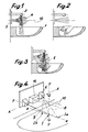
- 1 is a sink comprising a spout 2 for supplying water placed under the control of a detection unit 3.
- the detection zone 5 extends practically from the spout 2 to the bottom of the sink.
- the axes 8 and 9 are concurrent and contained in an inclined plane which lowers towards the bottom of the sink relative to the horizontal XX, the point of convergence I being located, substantially, on the vertical YY passing through the axis of the spout 2.
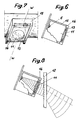
- a lens is placed in front of the radiating semiconductor element constituting the emitter, the axis of the lens is coincident with that of said element and practically the central emerging ray, that of Figures 1 and 4 , is perpendicular to the partition supporting the device.
- the central emerging ray, materialized by the axis 8, must be deflected towards the center. This result is obtained by shifting the optical axis of the lens 11 relative to that of the emitter 6. A analogous but symmetrical arrangement is adopted with regard to the receiver.
- the optical axes of the transmitter and the receiver are inclined as shown in FIGS. 7 to 8.
- a prism is placed in front of the lenses 11 Fresnel 12, made of a material allowing the infrared to pass through,
- Fresnel 12 made of a material allowing the infrared to pass through
- a plurality of prisms is used, the assembly thus constituted being able to serve as a protector for the device, the prism (s) 12 making it possible to widen the beam downwards the vertical plane.
- the device which has just been described must be able to be used whatever the distances between the spout 2 and the support wall on the one hand, and said spout and the bottom of the sink on the other hand. In other words, it is necessary to be able to vary the position of the point I where the axes 8 and 9 meet, and this, preferably, along a horizontal ZZ.
- each lens can be moved in a vertical direction and in a horizontal direction relative to the element in front of which it is placed.
- each lens 11 is carried by a slide 13 guided in a slide 14 of the housing 15 containing the transmitter or the receiver, the axis WW of the slide being inclined relative to the plane of symmetry of the device, which contains the YY axis.
- each slide allows a double adjustment.
- the meeting point I of the axes 8 and 9 is in Ia, that is to say further than that I on the same horizontal ZZ.
- the meeting point is in Ib, that is to say less far than that I on the same horizontal ZZ.
- the invention provides for associating a usual device with that of the invention, as is apparent from FIGS. 4 and 5.
- the usual device detects the zone located immediately in below the spout 2.
- the usual device 16 is arranged between the transmitter 6 and the receiver 7.
Landscapes
- Life Sciences & Earth Sciences (AREA)
- Engineering & Computer Science (AREA)
- Hydrology & Water Resources (AREA)
- Public Health (AREA)
- Water Supply & Treatment (AREA)
- Health & Medical Sciences (AREA)
- Geophysics And Detection Of Objects (AREA)
- Optical Communication System (AREA)
- Undergarments, Swaddling Clothes, Handkerchiefs Or Underwear Materials (AREA)
- Domestic Plumbing Installations (AREA)
- Indication Of The Valve Opening Or Closing Status (AREA)
- Lasers (AREA)
- Semiconductor Lasers (AREA)
Abstract
Description
La présente invention est relative à un dispositif de commande d'un robinet par détection optique.The present invention relates to a device for controlling a tap by optical detection.
On connaît des dispositifs selon lesquels on détecte la présence des mains ou du corps de l'utilisateur à l'aide d'un système opto-électronique qui déclenche l'écoulement de l'eau, l'arrêt de l'écoulement étant obtenu par l'éloignenent de l'usager.Devices are known according to which the presence of the user's hands or body is detected using an opto-electronic system which triggers the flow of water, the flow being stopped by move it away from the user.
Le dispositif de détection est réalisé par un émetteur produisant, par exemple, un rayon infrarouge qui est réfléchi par les mains ou le corps de l'utilisateur vers un récepteur sensible au rayon émis et qui délivre alors un signal, ce dernier étant amplifié et traité pour permettre la commande d'une électrovanne.The detection device is produced by a transmitter producing, for example, an infrared ray which is reflected by the hands or the body of the user towards a receiver sensitive to the ray emitted and which then delivers a signal, the latter being amplified and processed to allow control of a solenoid valve.
Dans ce genre d'appareil, l'émetteur et le récepteur sont physiquement très proches et le rayon incident se réfléchit pratiquement sur lui-même. De ce fait, la zone de détection est très réduite et elle est située sous le bec du robinet. Dans ces conditions, il n'est pas possible de maintenir l'écoulement de l'eau si les mains sortent de cette zone et plongent, par exemple, vers le fond du lavabo.In this type of device, the transmitter and the receiver are physically very close and the incident ray is practically reflected on itself. Therefore, the detection area is very small and it is located under the spout of the tap. Under these conditions, it is not possible to maintain the flow of water if the hands come out of this area and plunge, for example, towards the bottom of the sink.
Pour remédier à cet inconvénient, il est possible d'augmenter la portée du rayon incident de façon à détecter non plus les mains mais le corps de l'utilisateur. Cette solution n'est pas valable car on a constaté que le dispositif réagissait à la présence de toute personne située devant le lavabo même si cette dernière ne souhaitait pas se laver les mains ou passait, de façon intempestive, devant ledit lavabo et qu'il en résultait une consommation d'eau exagérée et inutile.To remedy this drawback, it is possible to increase the range of the incident ray so as to no longer detect the hands but the body of the user. This solution is not valid because it was found that the device reacted to the presence of any person located in front of the sink even if the latter did not wish to wash his hands or passed, inadvertently in front of said sink and that he The result was excessive and unnecessary water consumption.
La présente invention, qui remédie à ces inconvénients, est remarquable en ce que l'émetteur et le récepteur sont séparés et en ce que leurs axes sont concourants et contenus dans un plan incliné.The present invention, which overcomes these drawbacks, is remarkable in that the transmitter and the receiver are separate and in that their axes are concurrent and contained in an inclined plane.
La présente invention sera mieux comprise par la description qui va suivre faite en se référait aux dessins annexés, à titre d'exemple indicatif seulement, sur lesquels:
- les figures 1 et 2 sont des vues de côté montrant un dispositif connu;
- la figure 3 est une vue, analogue à celles précédentes, montrant le résultat obtenu à l'aide du dispositif de l'invention;
- la figure 4 est une vue schématique, en perspective, du dispositif de l'invention;
- la figure 5 est, à plus grande échelle, une vue analogue à celle 3;
- la figure 6 est une vue en coupe verticale d'un émetteur ou d'un récepteur;
- la figure 7 est la vue de droite de la figure 6;
- la figure 8 est une vue analogue à celle 6 montrant la possibilité d'élargir le faisceau incident.
- Figures 1 and 2 are side views showing a known device;
- Figure 3 is a view, similar to those preceding, showing the result obtained using the device of the invention;
- Figure 4 is a schematic perspective view of the device of the invention;
- Figure 5 is, on a larger scale, a view similar to that 3;
- Figure 6 is a vertical sectional view of a transmitter or a receiver;
- Figure 7 is the right view of Figure 6;
- Figure 8 is a view similar to that 6 showing the possibility of widening the incident beam.
En se reportant aux figures 1 et 2 on voit que, de la façon connue, 1 est un lavabo comportant un bec 2 d'alimentation en eau placé sous le contrôle d'un boitier de détection 3. Comme cela ressort de ces figures, les dispositifs de détection usuels dans lesquels l'émetteur et le récepteur sont physiquement très proches, les axes étant espacés de l'ordre d'une quinzaine de milimètres, la zone de détection est pratiquement limitée à celle schématisée en 4 sous le bec 2. Dès lors, si les mains de l'usager plongent vers le fond du lavabo 1, elles sortent de la zone 4 et l'alimentation en eau cesse.Referring to FIGS. 1 and 2, it can be seen that, in the known manner, 1 is a sink comprising a
Selon le dispositif de l'invention, et comme cela ressort de la figure 3, la zone 5 de détection s'étend pratiquement du bec 2 jusqu'au fond du lavabo.According to the device of the invention, and as can be seen from FIG. 3, the
Ce résultat est obtenu de la façon montrée, notamment sur la figure 4, selon laquelle l'émetteur, schématisé en 6, et le récepteur, schématisé en 7, sont physiquement séparés. L'espace entre l'axe 8 de l'émetteur et celui 9 du récepteur est de l'ordre d'une dizaine de centimètres.This result is obtained in the manner shown, in particular in FIG. 4, according to which the transmitter, shown schematically in 6, and the receiver, shown schematically in 7, are physically separated. The space between the
Les axes 8 et 9 sont concourants et contenus dans un plan incliné qui s'abaisse vers le fond du lavabo par rapport à l'horizontale XX, le point de convergence I étant situé, sensiblement, sur la verticale YY passant par l'axe du bec 2.The
Comme les axes 8 et 9 sont concourants si un rayon incident frappe le lavabo,surface très réfléchissante, le rayon réfléchi n'atteint pas le récepteur.As
A ce stade de la description, il convient de préciser ce que sont les axes 8 et 9. Ce ne sont pas les axes optiques du système mais les rayons les plus centraux des faisceaux.At this stage of the description, it is necessary to specify what the
Dans les systèmes de détection usuels, une lentille est placée devant l'élément semi-conducteur rayonnant constituant l'émetteur, l'axe de la lentille est confondu avec celui dudit élément et pratiquement le rayon émergeant central, celui 10 des figures 1 et 4, est perpendiculaire à la cloison supportant le dispositif.In the usual detection systems, a lens is placed in front of the radiating semiconductor element constituting the emitter, the axis of the lens is coincident with that of said element and practically the central emerging ray, that of Figures 1 and 4 , is perpendicular to the partition supporting the device.
Selon l'invention, le rayon émergeant central, matérialisé par l'axe 8, doit être dévié vers le centre. Ce résultat est obtenu en décalant l'axe optique de la lentille 11 par rapport à celui de l'émetteur 6. Une disposition analogue, mais symétrique, est adoptée en ce qui concerne le récepteur.According to the invention, the central emerging ray, materialized by the
Pour que le plan, contenant les axes 8 et 9, soit incliné vers le bas, on incline les axes optiques de l'émetteur et du récepteur comme cela ressort des figures 7 à 8. De plus, on place devant les lentilles 11 un prisme de Fresnel 12, réalisé en une matière laissant passer les infrarouges, Pratiquement, on utilise une pluralité de prismes, l'ensemble, ainsi constitué pouvant servir de protecteur au dispositif, le ou les prismes 12 permettant d'élargir le faisceau vers le bas dans le plan vertical.So that the plane, containing the
Le dispositif qui vient d'être décrit doit pouvoir être utilisé quel que soit les distances séparant le bec 2 et la paroi de support d'une part, et ledit bec et le fond du lavabo d'autre part. En d'autres termes, il faut pouvoir faire varier la position du point I de rencontre des axes 8 et 9.et ce, de préférence, selon une horizontale ZZ.The device which has just been described must be able to be used whatever the distances between the
Selon une autre caractéristique de l'invention, chaque lentille peut être déplacée selon une direction verticale et selon une direction horizontale par rapport à l'élément devant lequel elle est placée.According to another characteristic of the invention, each lens can be moved in a vertical direction and in a horizontal direction relative to the element in front of which it is placed.
Selon un mode de réalisation, chaque lentille 11 est portée par un coulisseau 13 guidé dans une glissière 14 du boitier 15 renfermant l'émetteur ou le récepteur, l'axe WW de la glissière étant incliné par rapport au plan de symétrie du dispositif, qui contient l'axe YY.According to one embodiment, each
Le déplacement de chaque coulisseau permet d'effectuer un double réglage. Lorsque les coulisseaux sont en position haute le point de rencontre I des axes 8 et 9 est en Ia, c'est-à-dire plus loin que celui I sur la même horizontale ZZ. Par contre, lorsque les coulisseaux sont en position basse, le point de rencontre est en Ib, c'est-à-dire moins loin que celui I sur la même horizontale ZZ.The movement of each slide allows a double adjustment. When the sliders are in the high position the meeting point I of the
Lorsque la hauteur de la zone de détection est importante, l'invention prévoit d'associer un dispositif usuel à celui de l'invention, comme cela ressort des figures 4 et 5. Dans ce cas, le dispositif usuel détecte la zone située immédiatement en dessous du bec 2. Comme cela ressort des dessins, le dispositif usuel 16 est disposé entre l'émetteur 6 et le récepteur 7.When the height of the detection zone is large, the invention provides for associating a usual device with that of the invention, as is apparent from FIGS. 4 and 5. In this case, the usual device detects the zone located immediately in below the
Claims (6)
Applications Claiming Priority (2)
| Application Number | Priority Date | Filing Date | Title |
|---|---|---|---|
| FR9003716 | 1990-03-23 | ||
| FR9003716A FR2660044B1 (en) | 1990-03-23 | 1990-03-23 | DEVICE FOR CONTROLLING A TAP BY OPTICAL DETECTION. |
Publications (2)
| Publication Number | Publication Date |
|---|---|
| EP0448421A1 true EP0448421A1 (en) | 1991-09-25 |
| EP0448421B1 EP0448421B1 (en) | 1994-08-31 |
Family
ID=9395029
Family Applications (1)
| Application Number | Title | Priority Date | Filing Date |
|---|---|---|---|
| EP91400392A Expired - Lifetime EP0448421B1 (en) | 1990-03-23 | 1991-02-15 | Valve operating means with optical detection |
Country Status (5)
| Country | Link |
|---|---|
| EP (1) | EP0448421B1 (en) |
| AT (1) | ATE110832T1 (en) |
| DE (1) | DE69103657T2 (en) |
| ES (1) | ES2060312T3 (en) |
| FR (1) | FR2660044B1 (en) |
Cited By (6)
| Publication number | Priority date | Publication date | Assignee | Title |
|---|---|---|---|---|
| EP0583785A1 (en) * | 1992-08-20 | 1994-02-23 | von Lepel, Freifrau, Barbara | Watertap with proximity sensor |
| EP0623710A1 (en) * | 1993-05-07 | 1994-11-09 | SCHROTT, Harald | Non-contact sanitary valve |
| US6192530B1 (en) * | 1999-05-17 | 2001-02-27 | Wen S. Dai | Automatic faucet |
| EP2236880A1 (en) * | 2008-01-29 | 2010-10-06 | Shanghai Kohler Electronics, Ltd. | Infrared induction device |
| CN106051290A (en) * | 2016-07-25 | 2016-10-26 | 无锡昊瑜节能环保设备有限公司 | Water outflowing control method of water faucet |
| CN106195390A (en) * | 2016-07-25 | 2016-12-07 | 无锡昊瑜节能环保设备有限公司 | A kind of water discharge of water faucet control method |
Citations (4)
| Publication number | Priority date | Publication date | Assignee | Title |
|---|---|---|---|---|
| GB2195763A (en) * | 1986-09-13 | 1988-04-13 | Theodoros Mastichiadis | Water tap |
| US4767922A (en) * | 1986-08-25 | 1988-08-30 | Honeywell Inc. | Hand presence activated water faucet controller |
| US4823414A (en) * | 1986-01-22 | 1989-04-25 | Water-Matic Corporation | Automatic faucet-sink control system |
| EP0347527A1 (en) * | 1988-03-28 | 1989-12-27 | Sloan Valve Company | Automatically operated water tap |
-
1990
- 1990-03-23 FR FR9003716A patent/FR2660044B1/en not_active Expired - Fee Related
-
1991
- 1991-02-15 DE DE69103657T patent/DE69103657T2/en not_active Expired - Fee Related
- 1991-02-15 ES ES91400392T patent/ES2060312T3/en not_active Expired - Lifetime
- 1991-02-15 AT AT91400392T patent/ATE110832T1/en not_active IP Right Cessation
- 1991-02-15 EP EP91400392A patent/EP0448421B1/en not_active Expired - Lifetime
Patent Citations (4)
| Publication number | Priority date | Publication date | Assignee | Title |
|---|---|---|---|---|
| US4823414A (en) * | 1986-01-22 | 1989-04-25 | Water-Matic Corporation | Automatic faucet-sink control system |
| US4767922A (en) * | 1986-08-25 | 1988-08-30 | Honeywell Inc. | Hand presence activated water faucet controller |
| GB2195763A (en) * | 1986-09-13 | 1988-04-13 | Theodoros Mastichiadis | Water tap |
| EP0347527A1 (en) * | 1988-03-28 | 1989-12-27 | Sloan Valve Company | Automatically operated water tap |
Cited By (9)
| Publication number | Priority date | Publication date | Assignee | Title |
|---|---|---|---|---|
| EP0583785A1 (en) * | 1992-08-20 | 1994-02-23 | von Lepel, Freifrau, Barbara | Watertap with proximity sensor |
| EP0623710A1 (en) * | 1993-05-07 | 1994-11-09 | SCHROTT, Harald | Non-contact sanitary valve |
| US6192530B1 (en) * | 1999-05-17 | 2001-02-27 | Wen S. Dai | Automatic faucet |
| EP2236880A1 (en) * | 2008-01-29 | 2010-10-06 | Shanghai Kohler Electronics, Ltd. | Infrared induction device |
| US20100308224A1 (en) * | 2008-01-29 | 2010-12-09 | Weigen Chen | Infrared sensing device |
| EP2236880A4 (en) * | 2008-01-29 | 2011-01-12 | Shanghai Kohler Electronics | Infrared induction device |
| US8421020B2 (en) * | 2008-01-29 | 2013-04-16 | Shanghai Kohler Electronics, Ltd. | Infrared sensing device |
| CN106051290A (en) * | 2016-07-25 | 2016-10-26 | 无锡昊瑜节能环保设备有限公司 | Water outflowing control method of water faucet |
| CN106195390A (en) * | 2016-07-25 | 2016-12-07 | 无锡昊瑜节能环保设备有限公司 | A kind of water discharge of water faucet control method |
Also Published As
| Publication number | Publication date |
|---|---|
| ES2060312T3 (en) | 1994-11-16 |
| FR2660044B1 (en) | 1992-08-14 |
| EP0448421B1 (en) | 1994-08-31 |
| DE69103657T2 (en) | 1995-03-23 |
| FR2660044A1 (en) | 1991-09-27 |
| DE69103657D1 (en) | 1994-10-06 |
| ATE110832T1 (en) | 1994-09-15 |
Similar Documents
| Publication | Publication Date | Title |
|---|---|---|
| EP1082622B1 (en) | Directional object sensor for automatic flow controller | |
| US5477984A (en) | Liquid jetting apparatus for jetting liquid toward a hand for disinfection thereof | |
| NL8005945A (en) | SHOWER HEAD. | |
| CA2603059A1 (en) | Automatic faucet with polarization sensor | |
| FR3049335A1 (en) | VEHICLE FIRE, VEHICLE FIRE CONTROL SYSTEM, AND VEHICLE COMPRISING THE SAME | |
| WO1998048370A1 (en) | Optoelectronic device for image acquisition, in particular of bar codes | |
| FR2772115A1 (en) | SURFACE ILLUMINATOR | |
| EP0448421B1 (en) | Valve operating means with optical detection | |
| US5773819A (en) | Single element light detector | |
| TW331001B (en) | Coin discriminating apparatus | |
| US20060278815A1 (en) | Regressive reflection type photoelectric switch | |
| EP0567357A1 (en) | Illuminated push-botton switch with channelled and diffused light flux | |
| JPH0452698Y2 (en) | ||
| US20080029771A1 (en) | Switch having a ball member | |
| US4963021A (en) | Photoelectric switching apparatus | |
| JPH10134680A (en) | Detecting sensor | |
| JPH10227635A (en) | Inclination sensor | |
| FR3010484A1 (en) | DEVICE FOR LIGHTING A MOTOR VEHICLE | |
| EP1286436A3 (en) | Wavelength monitor and laser module | |
| JP6315428B2 (en) | Automatic faucet device | |
| JP2739493B2 (en) | Diffuse reflection type photoelectric switch | |
| JPH0676704A (en) | Photoelectric switch | |
| JP7021586B2 (en) | Water spouting device | |
| US20040212805A1 (en) | Optical input device capable of determining properties of a reflective plane | |
| JPS6463911A (en) | Photodetection device |
Legal Events
| Date | Code | Title | Description |
|---|---|---|---|
| PUAI | Public reference made under article 153(3) epc to a published international application that has entered the european phase |
Free format text: ORIGINAL CODE: 0009012 |
|
| 17P | Request for examination filed |
Effective date: 19910510 |
|
| AK | Designated contracting states |
Kind code of ref document: A1 Designated state(s): AT BE CH DE DK ES FR GB GR IT LI LU NL SE |
|
| 17Q | First examination report despatched |
Effective date: 19930222 |
|
| GRAA | (expected) grant |
Free format text: ORIGINAL CODE: 0009210 |
|
| AK | Designated contracting states |
Kind code of ref document: B1 Designated state(s): AT BE CH DE DK ES FR GB GR IT LI LU NL SE |
|
| PG25 | Lapsed in a contracting state [announced via postgrant information from national office to epo] |
Ref country code: NL Effective date: 19940831 Ref country code: GR Free format text: LAPSE BECAUSE OF FAILURE TO SUBMIT A TRANSLATION OF THE DESCRIPTION OR TO PAY THE FEE WITHIN THE PRESCRIBED TIME-LIMIT Effective date: 19940831 Ref country code: GB Effective date: 19940831 Ref country code: DK Effective date: 19940831 |
|
| REF | Corresponds to: |
Ref document number: 110832 Country of ref document: AT Date of ref document: 19940915 Kind code of ref document: T |
|
| ITF | It: translation for a ep patent filed |
Owner name: D. PERROTTA & C. S.A.S. |
|
| REF | Corresponds to: |
Ref document number: 69103657 Country of ref document: DE Date of ref document: 19941006 |
|
| REG | Reference to a national code |
Ref country code: ES Ref legal event code: FG2A Ref document number: 2060312 Country of ref document: ES Kind code of ref document: T3 |
|
| PG25 | Lapsed in a contracting state [announced via postgrant information from national office to epo] |
Ref country code: SE Effective date: 19941130 |
|
| NLV1 | Nl: lapsed or annulled due to failure to fulfill the requirements of art. 29p and 29m of the patents act | ||
| PG25 | Lapsed in a contracting state [announced via postgrant information from national office to epo] |
Ref country code: LU Free format text: LAPSE BECAUSE OF NON-PAYMENT OF DUE FEES Effective date: 19950228 Ref country code: LI Effective date: 19950228 Ref country code: CH Effective date: 19950228 Ref country code: BE Effective date: 19950228 |
|
| GBV | Gb: ep patent (uk) treated as always having been void in accordance with gb section 77(7)/1977 [no translation filed] |
Effective date: 19940831 |
|
| PLBE | No opposition filed within time limit |
Free format text: ORIGINAL CODE: 0009261 |
|
| STAA | Information on the status of an ep patent application or granted ep patent |
Free format text: STATUS: NO OPPOSITION FILED WITHIN TIME LIMIT |
|
| 26N | No opposition filed | ||
| BERE | Be: lapsed |
Owner name: LES ROBINETS PRESTO Effective date: 19950228 |
|
| ITTA | It: last paid annual fee | ||
| PGFP | Annual fee paid to national office [announced via postgrant information from national office to epo] |
Ref country code: ES Payment date: 19990225 Year of fee payment: 9 |
|
| PGFP | Annual fee paid to national office [announced via postgrant information from national office to epo] |
Ref country code: FR Payment date: 19990226 Year of fee payment: 9 |
|
| PGFP | Annual fee paid to national office [announced via postgrant information from national office to epo] |
Ref country code: AT Payment date: 19990228 Year of fee payment: 9 |
|
| PGFP | Annual fee paid to national office [announced via postgrant information from national office to epo] |
Ref country code: DE Payment date: 19990429 Year of fee payment: 9 |
|
| PG25 | Lapsed in a contracting state [announced via postgrant information from national office to epo] |
Ref country code: AT Free format text: LAPSE BECAUSE OF NON-PAYMENT OF DUE FEES Effective date: 20000215 |
|
| PG25 | Lapsed in a contracting state [announced via postgrant information from national office to epo] |
Ref country code: ES Free format text: LAPSE BECAUSE OF NON-PAYMENT OF DUE FEES Effective date: 20000216 |
|
| PG25 | Lapsed in a contracting state [announced via postgrant information from national office to epo] |
Ref country code: FR Free format text: LAPSE BECAUSE OF NON-PAYMENT OF DUE FEES Effective date: 20001031 |
|
| PG25 | Lapsed in a contracting state [announced via postgrant information from national office to epo] |
Ref country code: DE Free format text: LAPSE BECAUSE OF NON-PAYMENT OF DUE FEES Effective date: 20001201 |
|
| REG | Reference to a national code |
Ref country code: FR Ref legal event code: ST |
|
| REG | Reference to a national code |
Ref country code: ES Ref legal event code: FD2A Effective date: 20011010 |
|
| PG25 | Lapsed in a contracting state [announced via postgrant information from national office to epo] |
Ref country code: IT Free format text: LAPSE BECAUSE OF NON-PAYMENT OF DUE FEES Effective date: 20050215 |