EP0434672B1 - Infusion pump - Google Patents
Infusion pump Download PDFInfo
- Publication number
- EP0434672B1 EP0434672B1 EP88905585A EP88905585A EP0434672B1 EP 0434672 B1 EP0434672 B1 EP 0434672B1 EP 88905585 A EP88905585 A EP 88905585A EP 88905585 A EP88905585 A EP 88905585A EP 0434672 B1 EP0434672 B1 EP 0434672B1
- Authority
- EP
- European Patent Office
- Prior art keywords
- syringe
- drive
- actuator
- pump
- arm
- Prior art date
- Legal status (The legal status is an assumption and is not a legal conclusion. Google has not performed a legal analysis and makes no representation as to the accuracy of the status listed.)
- Expired - Lifetime
Links
Images


Classifications
-
- A—HUMAN NECESSITIES
- A61—MEDICAL OR VETERINARY SCIENCE; HYGIENE
- A61M—DEVICES FOR INTRODUCING MEDIA INTO, OR ONTO, THE BODY; DEVICES FOR TRANSDUCING BODY MEDIA OR FOR TAKING MEDIA FROM THE BODY; DEVICES FOR PRODUCING OR ENDING SLEEP OR STUPOR
- A61M5/00—Devices for bringing media into the body in a subcutaneous, intra-vascular or intramuscular way; Accessories therefor, e.g. filling or cleaning devices, arm-rests
- A61M5/14—Infusion devices, e.g. infusing by gravity; Blood infusion; Accessories therefor
- A61M5/142—Pressure infusion, e.g. using pumps
- A61M5/145—Pressure infusion, e.g. using pumps using pressurised reservoirs, e.g. pressurised by means of pistons
- A61M5/1452—Pressure infusion, e.g. using pumps using pressurised reservoirs, e.g. pressurised by means of pistons pressurised by means of pistons
- A61M5/1456—Pressure infusion, e.g. using pumps using pressurised reservoirs, e.g. pressurised by means of pistons pressurised by means of pistons with a replaceable reservoir comprising a piston rod to be moved into the reservoir, e.g. the piston rod is part of the removable reservoir
-
- A—HUMAN NECESSITIES
- A61—MEDICAL OR VETERINARY SCIENCE; HYGIENE
- A61M—DEVICES FOR INTRODUCING MEDIA INTO, OR ONTO, THE BODY; DEVICES FOR TRANSDUCING BODY MEDIA OR FOR TAKING MEDIA FROM THE BODY; DEVICES FOR PRODUCING OR ENDING SLEEP OR STUPOR
- A61M5/00—Devices for bringing media into the body in a subcutaneous, intra-vascular or intramuscular way; Accessories therefor, e.g. filling or cleaning devices, arm-rests
- A61M5/14—Infusion devices, e.g. infusing by gravity; Blood infusion; Accessories therefor
- A61M5/142—Pressure infusion, e.g. using pumps
- A61M5/145—Pressure infusion, e.g. using pumps using pressurised reservoirs, e.g. pressurised by means of pistons
- A61M5/1452—Pressure infusion, e.g. using pumps using pressurised reservoirs, e.g. pressurised by means of pistons pressurised by means of pistons
- A61M5/1458—Means for capture of the plunger flange
-
- A—HUMAN NECESSITIES
- A61—MEDICAL OR VETERINARY SCIENCE; HYGIENE
- A61M—DEVICES FOR INTRODUCING MEDIA INTO, OR ONTO, THE BODY; DEVICES FOR TRANSDUCING BODY MEDIA OR FOR TAKING MEDIA FROM THE BODY; DEVICES FOR PRODUCING OR ENDING SLEEP OR STUPOR
- A61M5/00—Devices for bringing media into the body in a subcutaneous, intra-vascular or intramuscular way; Accessories therefor, e.g. filling or cleaning devices, arm-rests
- A61M5/14—Infusion devices, e.g. infusing by gravity; Blood infusion; Accessories therefor
- A61M5/168—Means for controlling media flow to the body or for metering media to the body, e.g. drip meters, counters ; Monitoring media flow to the body
- A61M5/16831—Monitoring, detecting, signalling or eliminating infusion flow anomalies
- A61M5/16854—Monitoring, detecting, signalling or eliminating infusion flow anomalies by monitoring line pressure
-
- Y—GENERAL TAGGING OF NEW TECHNOLOGICAL DEVELOPMENTS; GENERAL TAGGING OF CROSS-SECTIONAL TECHNOLOGIES SPANNING OVER SEVERAL SECTIONS OF THE IPC; TECHNICAL SUBJECTS COVERED BY FORMER USPC CROSS-REFERENCE ART COLLECTIONS [XRACs] AND DIGESTS
- Y10—TECHNICAL SUBJECTS COVERED BY FORMER USPC
- Y10S—TECHNICAL SUBJECTS COVERED BY FORMER USPC CROSS-REFERENCE ART COLLECTIONS [XRACs] AND DIGESTS
- Y10S128/00—Surgery
- Y10S128/01—Motorized syringe
-
- Y—GENERAL TAGGING OF NEW TECHNOLOGICAL DEVELOPMENTS; GENERAL TAGGING OF CROSS-SECTIONAL TECHNOLOGIES SPANNING OVER SEVERAL SECTIONS OF THE IPC; TECHNICAL SUBJECTS COVERED BY FORMER USPC CROSS-REFERENCE ART COLLECTIONS [XRACs] AND DIGESTS
- Y10—TECHNICAL SUBJECTS COVERED BY FORMER USPC
- Y10S—TECHNICAL SUBJECTS COVERED BY FORMER USPC CROSS-REFERENCE ART COLLECTIONS [XRACs] AND DIGESTS
- Y10S128/00—Surgery
- Y10S128/12—Pressure infusion
Definitions
- This invention relates to improvements in pumps far the delivery of drugs and other fluids in metered quantities.
- a wide range of controlled infusion pumps which are adapted to deliver drugs from a syringe are currently available and are widely use for a number of purposes in the medical field.
- Several of these pumps have a limited ability to "recognise” one or more standard syringe sizes (Atom 235 and Terufusion STC-521).
- Other pumps are highly programmable to accept a range of different standard syringes (Medfusion Systems - Model 1001, Vial Medical Program 3 and Sky Electronics - PS2000).
- a pump for the delivery of controlled amounts of fluid from a syringe having a body and a plunger comprising: means for receiving and locating the body of the syringe; syringe actuator means for engaging the plunger of the syringe held by said receiving and locating means; means for generating an electrical signal representing the position of said syringe actuator means; drive means connected to said actuator means to move the plunger into the syringe to deliver the fluid, said drive means including a permanently maintained connection between said actuator means and said means for generating said electrical signal representing the position of said actuator means; means for controlling said drive means; a movable arm for contacting the body of the syringe when held by said receiving and locating means; means for generating an electrical signal corresponding to the position of said arm when contacting the syringe body to provide a signal representative of the diameter of the syringe; means for inputting calibration data to said drive controlling means by storing the position of said actuator
- the infusion pump embodying the present invention will be seen to comprise a casing 1 within which the drive system embodying the invention is located, the casing 1 including a syringe cradle 2 having a centrally located groove 3 for locating the body of a syringe S (Fig. 3), and a slot 4 for receiving and locating the syringe flange.
- the syringe S is held in position in the groove 3 by means of a spring loaded syringe clamping arm 5 which is pivotally mounted within a housing 6 extending upwardly from the cradle 2.
- a syringe actuator 7 is mounted for sliding movement along a pair of guide rods 8 supported by the casing 1 and is driven by a driving mechanism located within the casing 1, and which will be described in greater detail below, to engage the plunger of the syringe S to cause the fluid contained in the syringe to be administered in a manner controlled by the central controlling system (Fig. 2) of the pump.
- the actuator 7 carries a proximity micro switch 9 and a clutch releasing button 10.
- the proximity microswitch 9 detects when the actuator 7 initially engages the plunger of the syringe so that the pump controller is made aware that contact with the plunger has occurred.
- the clutch releasing button 10 disengages the drive motor from the drive system to allow the actuator to be freely moved between its operating extremities for the purposes described further below.
- the infusion pump casing 1 includes a key pad 11 including the usual array of numerical keys, an enter key, a clear key and a stop key.
- a key pad 11 including the usual array of numerical keys, an enter key, a clear key and a stop key.
- several other keys 12 are also provided on the front panel, including:
- the central microprocessor 20 is typically a Z80 type and is under the control of EPROM 21, RAM 22, EEPROM 23, a key pad 11 and a clamping arm potentiometer 24 and a syringe actuator position potentiometer 25, via multiplexer 26 and analogue to digital converter 27.
- the controlling microprocessor 20 in turn controls the operation of a drive stepper motor 28 via a stepper driver circuit 29, the LCD display 13, an alarm buzzer 30 and a printer (not shown) via UART 31.
- the stepper drive circuit 29 is supplied by a power supply 32 which provides a regulated 5 volt rail and an eight volt rail for the stepper driver from a chargeable battery.
- the EPROM 21 contains the variable programmed information on which the pump controller operates, including a series of drug infusion profiles relating to various drugs to be infused.
- the RAM 22 constitutes the active memory of the control microprocessor 20 while the EEPROM 23 contains the fixed programme data, and is capable of storing data relating to the position of the clamping arm 5 when syringes S of predetermined volumes are loaded into the cradle 2.
- the controlling microprocessor 20 also receives electrical signals from microswitches which detect manual disengagement of the clutch, contact between the micro switch 9 and the plunger of the syringe S and unintended disengagement of the clutch caused by the occurrence of an occlusion preventing infusion.
- the syringe clamping arm 5 extends from a support 39 carried by a rotatably mounted shaft 40 supporting a notched cam 41 which is positioned to operate an on/off microswitch 42 when the clamping arm 5 is moved from its rest or lowest position to actuate the control system for the pump.
- the support is in the form of a cam which bears against a spring loaded lever (not shown) to supply a biasing force which holds the clamping arm 5 in engagement with a syringe carried by the cradle 2.
- the cam support 39 is arranged to be in the over-centre position when the clamping arm 5 is raised to its highest position. This enables the operator to position the clamping arm 5 at its highest point to enable loading of a syringe into the cradle 2.
- the shaft 40 further carries a gear wheel 43 which meshes with a pinion 44 carried by the shaft 45 of the potentiometer 24.
- the gear ratio of the gear 43 and pinion 44 which is usually about 4:1 or 5:1.
- the shaft 45 also carries a hair spring or watch spring 46 which has one end anchored to the casing 6 and the other end anchored to the shaft 45.
- the spring biases the pinion 44 in the required direction to prevent any backlash between the gears 43 and 44 being transmitted to the potentiometer 24.
- the shape of the clamping arm 5 is selected so that, for syringes in the range 10 to 50 ml in the syringe cradle 2, an approximately straight line relationship exists between the diameter of the syringe and the resistance of the potentiometer 24. In this way, the position of the clamping arm 5 is able to produce a voltage signal which provides an indication to the controlling computer 20 of the diameter of the syringe.
- clamping arm potentiometer voltage or "diameter" information corresponding to four selected syringe sizes, such as, 10, 20, 30 and 50 ml, may be stored in the EEPROM 23 either before sale, during sale or after sale.
- a diameter voltage signal is generated by the potentiometer 24 and is transmitted via the multiplexer 26 and the analog to digital converter 27 to the central controlling microprocessor 20.
- This diameter signal is compared with the programmed diameter information contained in the EEPROM 23, which will usually be in the form of a look-up table, and if the diameter signal corresponds to one of the standard diameters within a reasonable tolerance such as ⁇ 2.5%, the controller 20 will cause the corresponding volume of that syringe to be displayed on the LCD display 13 so that the operator may confirm that the volume displayed is the correct volume of the syringe which has been inserted by pressing the YES button. Once confirmation has been entered by the operator, the pump is ready to operate according to a selected infusion rate profile in the general manner described in the co-pending applications referred to above.
- non-standard a syringe for which the pump has not previously been calibrated
- the drive system comprises the stepping motor 28, which is horizontally mounted on a vertical support plate 50 having a horizontal portion 51 which is attached to the frame 52 which supports the cover 1.
- the stepper motor 28 is an ESCAP step motor P310, which has been found to be particularly suitable for the present purpose, and superior in operation to other stepper motors. While the use of a stepper motor, and particularly the above stepper motor, is particularly preferred since it enables highly accurate and rapid positioning of the drive system and therefore highly accurate and fast operation of the infusion pump, it should be appreciated that other forms of motor may be used to achieve acceptable results.
- a worm gear 53 is fixed to the output shaft of the stepper motor 28and is supported by a bearing plate 54 attached to the plate portion 51.
- the worm gear 53 meshes with a worm wheel 55 having a splined hub or pinion 56, the worm wheel 55 and pinion 56 being supported in a bearing 57 mounted on the frame 52 and a bearing 58 mounted in an overlying support plate 59 attached to the plate 50.
- the support plate 50 and the frame portion 52 are in the preferred embodiment formed as a removable unit, to enable the motor 50, worm gear 53 and the worm wheel 55 to be separated as a unit to enable easy adjustment, repair or replacement.
- An output reduction gear 60 meshes with the splined hub 56 and is drivingly attached to a drive head 61 via a sprag clutch 62.
- the sprag clutch 62 is of known construction and includes interengaged tooth elements 63,64 normally held in engagement with each other by means of a compression spring 65.
- the biasing force applied by the compression spring 65 is adjustable by means of packing washers 66 to vary the load at which the clutch 62 will automatically disengage when an undesirable over-pressure develops in the infusion line for the syringe S.
- the drive head 61 is supported by the frame 52 and by a saddle frame 67 carrying a bearing 68 supporting the uppermost end of the drive head 61.
- the sprag clutch 62 is also manually releasable by moving the lower most toothed element 64 against the action of the spring 65 by means of a lever arm 69 positioned between the frame 52 and an actuating sleeve 70 surrounding the clutch elements 63,64.
- the lever 69 is connected via a linkage 71 to a pivoted bar 72 which is pivoted by operation of the clutch release button 10 carried by the syringe actuator 7.
- the mechanism for achieving clutch release is essentially as described in the co-pending application referred to above, although only one tube is used to transmit the clutch releasing movement.
- the button 10 is positioned to engage a radial arm 90 connected to one of the tubes 89 surrounding guide rods 8.
- the tube 89 is rotatable within the actuator 7 (and within slider 88) and carries a drive release cam 90 which is positioned to engage the pivoted bar 72 when the tube 89 rotates in response to movement of arm 90 caused by manual depression of button 10.
- a microswitch 73 is positioned between the frame 52 and the uppermost face of the out put gear 60 so that an electrical signal is created whenever the sprag clutch 62 is partially or fully disengaged. While the microswitch 73 is in the present embodiment mounted on the output gear 60, it may be more conveniently located within the sprag clutch 62 itself. Furthermore, in order to distinguish between clutch disengagements caused by operation of the clutch release button 10 and clutch disengagements caused by clutch overload, such as would occur in the event of an occlusion, a further microswitch 73a is positioned adjacent to the pivoted bar 72 to detect operation of the clutch release mechanism before clutch release occurs. These different inputs to the microprocessor 20 are labelled “manual override” and “occlusion sensor”. The input labelled "head engaged" inputs signals generated by the microswitch 9.
- the drive head 61 includes a central toothed portion 82 which is drivingly engaged by a toothed drive belt 83 which engages a further drive head 84, similar to the drive head 61, mounted for rotation at the opposite end of the frame 52.
- the shaft of the drive head 84 is connected to a potentiometer 25 by means of which the position of the drive belt 83 is accurately monitored at all times.
- the drive belt 83 is permanently connected to syringe actuator 7 by means of a belt clamp 86 having a connector plate 87 which is in turn attached to a slider 88 connected to the syringe actuator 7 by a pair of tubes 89, the assembly being slidably mounted on the guide rods 8 carried by the casing 1 and the syringe cradle 2.
- the potentiometer 25 is at all times able to accurately sense the position of the syringe actuator 7, even where the drive clutch 62 is disconnected by means of depression of the button 10 and the syringe actuator 7 is moved freely along its guide rods 8 to perform a manual infusion or to programme the controller to operate with a non-standard syringe.
- the controller will detect the presence of a non-standard syringe in the syringe cradle 2 and will advise the operator via the LCD display 13 that programming is required before infusion may proceed.
- an empty syringe of the required volume is first loaded into the syringe cradle 2 and the clamping arm 5 lowered.
- the syringe actuator 7 is then slid along its guide rods 8 after releasing the clutch by means of button 10.
- the controller will then move the syringe actuator 7 until the microswitch 9 closes indicating that contact with the syringe plunger has occurred.
- the position of the syringe actuator 7 required to empty the desired syringe is indicated by the potentiometer 25 and the controller 20 receives this data via the multiplexer 26 and the analog to digital converter 27.
- the empty syringe is then removed and the syringe actuator 7 returned to its rest position.
- a full syringe is then loaded into the syringe cradle 2 and the clamping arm 5 lowered.
- the syringe actuator 7 is then advanced either manually, or under the action of the controller until the microswitch 9 contacts the syringe plunger.
- the starting position of the syringe actuator 7 prior to infusion occurring is then input to the controller 20 from the potentiometer 25.
- the controller causes the LCD display 13 to request the operator to input the volume of the non-standard syringe whereupon the necessary delivery factor is calculated by dividing that volume by the distance measurement derived from the data relating to the respective positions of the syringe actuator 7 described above.
- the controller is then ready to perform the desired infusion profile using the last programmed non-standard syringe.
- only four calibrations may be stored in the look-up table, and if a further non-standard syringe is to be used, the data relating to that syringe will replace one of the previously input 'diameters'.
- the ability to store syringe 'diameters' may be expanded if desired although it is currently thought that four should be sufficient.
- microswitch 42 causes the controller to be powered up and the LCD display 13 displays the message: LOAD FILLED SYRINGE AND LOWER CLAMP If the syringe is a "standard” syringe, that is, one which has previously been calibrated and has its "diameter” reading in the look-up table contained in EEPROM 23, and assuming the syringe is a 60 mL syringe containing 50 mL of fluid, the display will register the message: If the operator is satisfied with the estimated volume, and presses the YES button, the display 13 will register: If a new infusion is required, the operator presses the YES button and the display 13 reads: FIXED OR PROGRAMMED?
- the display 13 will request the required rate to be input using the key pad 11. If the operator selects programmed, the display 13 requests the operator to input the desired drug and patient data in a manner similar to that described in the co-pending application referred to above.
- the following display appears: If the operator enters the correct volume and it is within ⁇ 2.5% of 50 mL the system will allow infusion to proceed. If the entered volume is outside ⁇ 2.5%, or if the "clear" button is pressed, the following display appears: The controller moves the syringe actuator 7 towards the plunger until the microswitch 9 closes. The voltage reading from the potentiometer 24 is entered into EEPROM 23 in the look-up table at the diameter value closest to it.
- the voltage from the potentiometer 25 is entered into the look-up table and the display 13 then reads:
- the controller moves the syringe actuator 7 into engagement with the plunger of the filled syringe until the switch 9 closes at which time the voltage from the potentiometer 25 is entered into EEPROM 23.
- the "delivery factor" resulting from the volume and position data referred to above is calculated and the display 13 reads: The operator then proceeds as described above.
- the infusion pump embodying the present invention is, in addition to the functions described above, also capable of performing each of the functions described in greater detail in the co-pending patent applications referred to above.
- the infusion pump embodying the invention reference should be had to the description and drawings contained in the specifications accompanying those applications.
- the preferred embodiment of the drive system is designed to provide a total reduction ratio of 1000:1 in a particularly compact and simple manner from an engineering point of view.
- the arrangement described enables the infusion pump to deliver fluids within the range 0.1ml/hr to 1500ml/hr without any recoil or drive integrity problems.
- commercially available infusion pumps have delivery rate ranges of the order of 0.1ml/hr to 150ml/hr which is insufficient for the drug infusion control system described in greater detail in the co-pending applications
- the present drive system is capable of actuating the syringe at rates up to 10 times the rate achieved by existing devices.
- the particularly preferred stepper motor selected for use in the present embodiment enables adequate torque to be maintained at speed ranges up to 3000rpm, thus facilitating the high delivery rates referred to above.
- the use of a sprag clutch as the clutch means is desirable since it spreads the load over a large number of teeth and minimizes wear.
- the spring loading of the sprag clutch permits adjustment of the disengagement force to suit varying requirements.
- the use of a splined hub or pinion enables the sprag clutch to be suitably located and to permit disengagement of the clutch under load.
- the infusion pump and drive system will work equally well in either direction and accordingly the pump may be used to withdraw liquids as well as deliver them.
- certain types of blood analysis require rapid withdrawal of a quantity of blood to be analysed and the drive system according to the above embodiment would enable such rapid withdrawal to be achieved.
- the pump may be used to pump fluids other than drugs.
Landscapes
- Health & Medical Sciences (AREA)
- Vascular Medicine (AREA)
- Engineering & Computer Science (AREA)
- Anesthesiology (AREA)
- Biomedical Technology (AREA)
- Heart & Thoracic Surgery (AREA)
- Hematology (AREA)
- Life Sciences & Earth Sciences (AREA)
- Animal Behavior & Ethology (AREA)
- General Health & Medical Sciences (AREA)
- Public Health (AREA)
- Veterinary Medicine (AREA)
- Infusion, Injection, And Reservoir Apparatuses (AREA)
Abstract
Description
- This invention relates to improvements in pumps far the delivery of drugs and other fluids in metered quantities.
- In our co-pending patent application AU-A42019/85 (United States Patent No. 4,741,732 Crankshaw et al), the disclosure of which is incorporated herein by cross reference, we described a drug infusion pump having a drive system including a drive wheel on the output shaft of a DC gear motor biased to engage a resilient drive ring on a drive wheel which transmits drive to a drive head engaged by a toothed drive belt. While the described drive system was acceptable for an experimental pump designed to establish the workability of the drug infusion control system described in the application, subsequent consideration of the drive system revealed that it had certain shortcomings which made it unsuitable for commercial application.
- A wide range of controlled infusion pumps which are adapted to deliver drugs from a syringe are currently available and are widely use for a number of purposes in the medical field. Several of these pumps have a limited ability to "recognise" one or more standard syringe sizes (Atom 235 and Terufusion STC-521). Other pumps are highly programmable to accept a range of different standard syringes (Medfusion Systems - Model 1001, Vial Medical
Programme 3 and Sky Electronics - PS2000). However, none of the programmable infusion pumps currently available are able to recognise when a non-standard syringe is fitted to the pump or have the ability for the operator to input data relating to a non-standard syringe on the basis of which the delivery of fluid from such a syringe may be accurately controlled. The danger flowing from the above inability is the possibility of inaccurate pumping in the event that a non-standard syringe is used. At least some of the above pumps will operate when a non-standard syringe is inserted on the assumption one of the programmed standard syringes has in fact been inserted. The dangers of this type of operation are clearly obvious. - According to the present invention, there is provided a pump for the delivery of controlled amounts of fluid from a syringe having a body and a plunger, comprising: means for receiving and locating the body of the syringe; syringe actuator means for engaging the plunger of the syringe held by said receiving and locating means; means for generating an electrical signal representing the position of said syringe actuator means; drive means connected to said actuator means to move the plunger into the syringe to deliver the fluid, said drive means including a permanently maintained connection between said actuator means and said means for generating said electrical signal representing the position of said actuator means; means for controlling said drive means; a movable arm for contacting the body of the syringe when held by said receiving and locating means; means for generating an electrical signal corresponding to the position of said arm when contacting the syringe body to provide a signal representative of the diameter of the syringe; means for inputting calibration data to said drive controlling means by storing the position of said actuator means when engaged with the plunger of the syringe when empty, and storing the position of said actuator means when engaged with the plunger of the syringe when full; means for allowing a user to input the volume of the syringe; and means for calculating, from the stored positions of said actuator means and the volume of the syringe inputted by the user, a delivery factor which is used by said drive controlling means to control the delivery of the fluid contained in the syringe at a predetermined delivery rate; characterized in that the pump further comprises: memory means for storing data relating to one or more syringe diameters and delivery factor information corresponding thereto; logic means for determining whether the value of said electrical signal corresponding to the arm position corresponds to a syringe diameter represented by said stored data and for outputting an output signal representing the result of that determination; and means, responsive to said output signal being representative of a positive determination, for retrieving from said memory means a delivery factor corresponding to the diameter of the syringe; wherein said calibration data inputting means is arranged to input said calibration data in response to said output signal being representative of a negative determination.
- It will be appreciated from the above that an operator may quickly calibrate the pump to control the delivery of fluid for any syringe, even when an operation is in progress. This is important in the case of the infusion of anaesthetics since some drugs allow the patient to resume consciousness in a very short period of time, e.g. 2 minutes.
- One preferred form of the invention will now be described with reference to the accompanying drawings in which:
- Figure 1 is a perspective view of a pump embodying the invention;
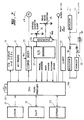
- Figure 2 is a schematic block diagram of the control system for the pump;
- Figure 3 is a fragmentary illustrative sectional elevation of the pump of Fig. 1 taken along the nominal line 3-3 in Fig. 1;
- Figure 4 is a fragmentary plan view taken along the line 4-4 in Fig. 3; and
- Figure 5 is a sectional end elevation taken along the line 5-5 in Fig. 4.
- Referring first to Figure 1 of the drawings, the infusion pump embodying the present invention will be seen to comprise a
casing 1 within which the drive system embodying the invention is located, thecasing 1 including asyringe cradle 2 having a centrally locatedgroove 3 for locating the body of a syringe S (Fig. 3), and aslot 4 for receiving and locating the syringe flange. The syringe S is held in position in thegroove 3 by means of a spring loadedsyringe clamping arm 5 which is pivotally mounted within ahousing 6 extending upwardly from thecradle 2. Asyringe actuator 7 is mounted for sliding movement along a pair ofguide rods 8 supported by thecasing 1 and is driven by a driving mechanism located within thecasing 1, and which will be described in greater detail below, to engage the plunger of the syringe S to cause the fluid contained in the syringe to be administered in a manner controlled by the central controlling system (Fig. 2) of the pump. Theactuator 7 carries aproximity micro switch 9 and aclutch releasing button 10. Theproximity microswitch 9 detects when theactuator 7 initially engages the plunger of the syringe so that the pump controller is made aware that contact with the plunger has occurred. Theclutch releasing button 10 disengages the drive motor from the drive system to allow the actuator to be freely moved between its operating extremities for the purposes described further below. - The
infusion pump casing 1 includes akey pad 11 including the usual array of numerical keys, an enter key, a clear key and a stop key. In addition, severalother keys 12 are also provided on the front panel, including: - BATT TEST -
- enables the charged state of the battery to be ascertained. An associated LED indicates if charging is in progress.
- ALARM -
- enables an alarm to be cancelled. An associated LED flashes when the alarm is tripped.
- RUN -
- enables operation of the pump to commence. An associated LED illuminates when the run button is pressed.
- BOLUS -
- causes bolus infusion, overriding the control program and causing infusion at a rate approximately equal to manual infusion. Again a LED illuminates when the bolus key is pressed.
- STOP -
- stops the pump.
- ASSIST -
- causes the interaction assistance programme to operate.
- YES -
- enables a positive reply to the input.
- NO -
- enables a negative reply to the input.
- Referring now to Figure 2 of the drawings, a block diagram of the pump controller circuitry is shown. The
central microprocessor 20 is typically a Z80 type and is under the control of EPROM 21,RAM 22, EEPROM 23, akey pad 11 and aclamping arm potentiometer 24 and a syringeactuator position potentiometer 25, viamultiplexer 26 and analogue todigital converter 27. The controllingmicroprocessor 20 in turn controls the operation of adrive stepper motor 28 via astepper driver circuit 29, theLCD display 13, an alarm buzzer 30 and a printer (not shown) via UART 31. Thestepper drive circuit 29 is supplied by apower supply 32 which provides a regulated 5 volt rail and an eight volt rail for the stepper driver from a chargeable battery. - The EPROM 21 contains the variable programmed information on which the pump controller operates, including a series of drug infusion profiles relating to various drugs to be infused. In this regard, reference is made to the copending patent application referred to above where the drug infusion profiles and the method of derivation thereof are now fully described. Further description of the profiles will not be provided since the present application is concerned primarily with the drive system for the infusion pump and the basic control system therefor. The
RAM 22 constitutes the active memory of thecontrol microprocessor 20 while the EEPROM 23 contains the fixed programme data, and is capable of storing data relating to the position of theclamping arm 5 when syringes S of predetermined volumes are loaded into thecradle 2. - The controlling
microprocessor 20 also receives electrical signals from microswitches which detect manual disengagement of the clutch, contact between themicro switch 9 and the plunger of the syringe S and unintended disengagement of the clutch caused by the occurrence of an occlusion preventing infusion. - Referring now to figures 3 to 5 of the accompanying drawings, the
syringe clamping arm 5 extends from asupport 39 carried by a rotatably mountedshaft 40 supporting a notchedcam 41 which is positioned to operate an on/offmicroswitch 42 when theclamping arm 5 is moved from its rest or lowest position to actuate the control system for the pump. The support is in the form of a cam which bears against a spring loaded lever (not shown) to supply a biasing force which holds theclamping arm 5 in engagement with a syringe carried by thecradle 2. Thecam support 39 is arranged to be in the over-centre position when theclamping arm 5 is raised to its highest position. This enables the operator to position the clampingarm 5 at its highest point to enable loading of a syringe into thecradle 2. - The
shaft 40 further carries agear wheel 43 which meshes with apinion 44 carried by theshaft 45 of thepotentiometer 24. In this way, the full angular movement through about 35 degrees of theclamping arm 5 is amplified by the gear ratio of thegear 43 andpinion 44, which is usually about 4:1 or 5:1. Thus, a very small variation in the position of theclamping arm 5 produces a readily discernible change in the resistance of thepotentiometer 24 thereby resulting in a change in the voltage signal delivered to themultiplexer 26. - The
shaft 45 also carries a hair spring orwatch spring 46 which has one end anchored to thecasing 6 and the other end anchored to theshaft 45. The spring biases thepinion 44 in the required direction to prevent any backlash between thegears potentiometer 24. - The shape of the
clamping arm 5 is selected so that, for syringes in therange 10 to 50 ml in thesyringe cradle 2, an approximately straight line relationship exists between the diameter of the syringe and the resistance of thepotentiometer 24. In this way, the position of theclamping arm 5 is able to produce a voltage signal which provides an indication to the controllingcomputer 20 of the diameter of the syringe. - In the present embodiment, clamping arm potentiometer voltage or "diameter" information corresponding to four selected syringe sizes, such as, 10, 20, 30 and 50 ml, may be stored in the
EEPROM 23 either before sale, during sale or after sale. Thus, when a selected syringe is loaded into thecradle 2 and theclamping arm 5 is lowered into engagement with the body of the syringe, a diameter voltage signal is generated by thepotentiometer 24 and is transmitted via themultiplexer 26 and the analog todigital converter 27 to the central controllingmicroprocessor 20. This diameter signal is compared with the programmed diameter information contained in theEEPROM 23, which will usually be in the form of a look-up table, and if the diameter signal corresponds to one of the standard diameters within a reasonable tolerance such as ± 2.5%, thecontroller 20 will cause the corresponding volume of that syringe to be displayed on theLCD display 13 so that the operator may confirm that the volume displayed is the correct volume of the syringe which has been inserted by pressing the YES button. Once confirmation has been entered by the operator, the pump is ready to operate according to a selected infusion rate profile in the general manner described in the co-pending applications referred to above. - In the event that a syringe for which the pump has not previously been calibrated (hereinafter "non-standard") is inserted into the
syringe cradle 2, the diameter signal generated by thepotentiometer 24 will not correspond to any one of the programmed diameters and the controller must then be manually programmed or recalibrated to enable operation using this non-standard syringe. Before describing the manner of programming the controller to accept a non-standard syringe, it is appropriate to further describe the drive system with reference to Figures 3 to 5 of the drawings. - The drive system comprises the stepping
motor 28, which is horizontally mounted on avertical support plate 50 having ahorizontal portion 51 which is attached to theframe 52 which supports thecover 1. In the present embodiment, thestepper motor 28 is an ESCAP step motor P310, which has been found to be particularly suitable for the present purpose, and superior in operation to other stepper motors. While the use of a stepper motor, and particularly the above stepper motor, is particularly preferred since it enables highly accurate and rapid positioning of the drive system and therefore highly accurate and fast operation of the infusion pump, it should be appreciated that other forms of motor may be used to achieve acceptable results. - A
worm gear 53 is fixed to the output shaft of the stepper motor 28and is supported by a bearingplate 54 attached to theplate portion 51. Theworm gear 53 meshes with aworm wheel 55 having a splined hub orpinion 56, theworm wheel 55 andpinion 56 being supported in abearing 57 mounted on theframe 52 and abearing 58 mounted in anoverlying support plate 59 attached to theplate 50. - The
support plate 50 and theframe portion 52 are in the preferred embodiment formed as a removable unit, to enable themotor 50,worm gear 53 and theworm wheel 55 to be separated as a unit to enable easy adjustment, repair or replacement. - An
output reduction gear 60 meshes with thesplined hub 56 and is drivingly attached to adrive head 61 via a sprag clutch 62. The sprag clutch 62 is of known construction and includesinterengaged tooth elements compression spring 65. The biasing force applied by thecompression spring 65 is adjustable by means of packingwashers 66 to vary the load at which the clutch 62 will automatically disengage when an undesirable over-pressure develops in the infusion line for the syringe S. - The
drive head 61 is supported by theframe 52 and by asaddle frame 67 carrying abearing 68 supporting the uppermost end of thedrive head 61. - The sprag clutch 62 is also manually releasable by moving the lower most
toothed element 64 against the action of thespring 65 by means of alever arm 69 positioned between theframe 52 and anactuating sleeve 70 surrounding theclutch elements lever 69 is connected via alinkage 71 to a pivotedbar 72 which is pivoted by operation of theclutch release button 10 carried by thesyringe actuator 7. The mechanism for achieving clutch release is essentially as described in the co-pending application referred to above, although only one tube is used to transmit the clutch releasing movement. - The
button 10 is positioned to engage aradial arm 90 connected to one of thetubes 89 surroundingguide rods 8. As described in greater detail in the co-pending application, thetube 89 is rotatable within the actuator 7 (and within slider 88) and carries adrive release cam 90 which is positioned to engage the pivotedbar 72 when thetube 89 rotates in response to movement ofarm 90 caused by manual depression ofbutton 10. - A
microswitch 73 is positioned between theframe 52 and the uppermost face of the out putgear 60 so that an electrical signal is created whenever the sprag clutch 62 is partially or fully disengaged. While themicroswitch 73 is in the present embodiment mounted on theoutput gear 60, it may be more conveniently located within the sprag clutch 62 itself. Furthermore, in order to distinguish between clutch disengagements caused by operation of theclutch release button 10 and clutch disengagements caused by clutch overload, such as would occur in the event of an occlusion, afurther microswitch 73a is positioned adjacent to the pivotedbar 72 to detect operation of the clutch release mechanism before clutch release occurs. These different inputs to themicroprocessor 20 are labelled "manual override" and "occlusion sensor". The input labelled "head engaged" inputs signals generated by themicroswitch 9. - The
drive head 61 includes a centraltoothed portion 82 which is drivingly engaged by atoothed drive belt 83 which engages afurther drive head 84, similar to thedrive head 61, mounted for rotation at the opposite end of theframe 52. The shaft of thedrive head 84 is connected to apotentiometer 25 by means of which the position of thedrive belt 83 is accurately monitored at all times. Thedrive belt 83 is permanently connected tosyringe actuator 7 by means of abelt clamp 86 having aconnector plate 87 which is in turn attached to aslider 88 connected to thesyringe actuator 7 by a pair oftubes 89, the assembly being slidably mounted on theguide rods 8 carried by thecasing 1 and thesyringe cradle 2. In this way, a permanent driving connection is effected between thedrive belt 83 and thesyringe actuator 7, which driving connection is maintained irrespective of release of the sprag clutch 62 by means of theclutch release button 10. Thus, the position of thesyringe actuator 7 is always known by the central controllingcomputer 20 since the voltage signal generated by thepotentiometer 25 is fed to themicroprocessor 20 viamultiplexer 26 and analog todigital converter 27 whereby the position of thesyringe actuator 7 and the distance it has travel led during any particular time period may be determined by themicroprocessor 20. - It will be appreciated from the above that since a permanent driving connection is maintained between the
drive belt 83 and thesyringe actuator 7, thepotentiometer 25 is at all times able to accurately sense the position of thesyringe actuator 7, even where the drive clutch 62 is disconnected by means of depression of thebutton 10 and thesyringe actuator 7 is moved freely along itsguide rods 8 to perform a manual infusion or to programme the controller to operate with a non-standard syringe. - As described above, the controller will detect the presence of a non-standard syringe in the
syringe cradle 2 and will advise the operator via theLCD display 13 that programming is required before infusion may proceed. To programme for a non-standard syringe, an empty syringe of the required volume is first loaded into thesyringe cradle 2 and theclamping arm 5 lowered. Thesyringe actuator 7 is then slid along itsguide rods 8 after releasing the clutch by means ofbutton 10. The controller will then move thesyringe actuator 7 until themicroswitch 9 closes indicating that contact with the syringe plunger has occurred. In this way the position of thesyringe actuator 7 required to empty the desired syringe is indicated by thepotentiometer 25 and thecontroller 20 receives this data via themultiplexer 26 and the analog todigital converter 27. The empty syringe is then removed and thesyringe actuator 7 returned to its rest position. A full syringe is then loaded into thesyringe cradle 2 and theclamping arm 5 lowered. Thesyringe actuator 7 is then advanced either manually, or under the action of the controller until themicroswitch 9 contacts the syringe plunger. The starting position of thesyringe actuator 7 prior to infusion occurring is then input to thecontroller 20 from thepotentiometer 25. After this procedure is completed, the controller causes theLCD display 13 to request the operator to input the volume of the non-standard syringe whereupon the necessary delivery factor is calculated by dividing that volume by the distance measurement derived from the data relating to the respective positions of thesyringe actuator 7 described above. The controller is then ready to perform the desired infusion profile using the last programmed non-standard syringe. In the present embodiment, only four calibrations may be stored in the look-up table, and if a further non-standard syringe is to be used, the data relating to that syringe will replace one of the previously input 'diameters'. Of course, the ability to store syringe 'diameters' may be expanded if desired although it is currently thought that four should be sufficient. - A typical series of operator prompts displayed on the
LCD display 13 for a range of modes of operation will now be described to assist in a more complete understanding of the embodiment described above. - When the
syringe clamping arm 5 is initially lifted from its rest position,microswitch 42 causes the controller to be powered up and theLCD display 13 displays the message:
LOAD FILLED SYRINGE AND LOWER CLAMP
If the syringe is a "standard" syringe, that is, one which has previously been calibrated and has its "diameter" reading in the look-up table contained inEEPROM 23, and assuming the syringe is a 60 mL syringe containing 50 mL of fluid, the display will register the message:
If the operator is satisfied with the estimated volume, and presses the YES button, thedisplay 13 will register:
If a new infusion is required, the operator presses the YES button and thedisplay 13 reads:
FIXED OR PROGRAMMED?
If the operator selects FIXED, thedisplay 13 will request the required rate to be input using thekey pad 11. If the operator selects programmed, thedisplay 13 requests the operator to input the desired drug and patient data in a manner similar to that described in the co-pending application referred to above. - In the event that the estimated volume reading referred to above is incorrect, the following display appears:

If the operator enters the correct volume and it is within ± 2.5% of 50 mL the system will allow infusion to proceed. If the entered volume is outside ± 2.5%, or if the "clear" button is pressed, the following display appears:
The controller moves thesyringe actuator 7 towards the plunger until themicroswitch 9 closes. The voltage reading from thepotentiometer 24 is entered intoEEPROM 23 in the look-up table at the diameter value closest to it. The voltage from thepotentiometer 25 is entered into the look-up table and thedisplay 13 then reads:
The controller moves thesyringe actuator 7 into engagement with the plunger of the filled syringe until theswitch 9 closes at which time the voltage from thepotentiometer 25 is entered intoEEPROM 23. The "delivery factor" resulting from the volume and position data referred to above is calculated and thedisplay 13 reads:
The operator then proceeds as described above. - It should be appreciated that the infusion pump embodying the present invention is, in addition to the functions described above, also capable of performing each of the functions described in greater detail in the co-pending patent applications referred to above. Thus, for a complete understanding of the infusion pump embodying the invention, reference should be had to the description and drawings contained in the specifications accompanying those applications.
- The preferred embodiment of the drive system is designed to provide a total reduction ratio of 1000:1 in a particularly compact and simple manner from an engineering point of view. The arrangement described enables the infusion pump to deliver fluids within the range 0.1ml/hr to 1500ml/hr without any recoil or drive integrity problems. As a matter of comparison, commercially available infusion pumps have delivery rate ranges of the order of 0.1ml/hr to 150ml/hr which is insufficient for the drug infusion control system described in greater detail in the co-pending applications Thus, for a given syringe size, the present drive system is capable of actuating the syringe at rates up to 10 times the rate achieved by existing devices. The particularly preferred stepper motor selected for use in the present embodiment enables adequate torque to be maintained at speed ranges up to 3000rpm, thus facilitating the high delivery rates referred to above.
- It will also be appreciated that the worm drive system described in greater detail above offers the following specific advantages:
- 1. Prevents reversing of the drive motor under load (as outlined in greater detail above) and renders the system effectively self locking.
- 2. Permits depowering of the stepper motor between steps and makes it unnecessary to hold the motor between steps, thereby reducing power drain.
- 3. Provides a high reduction ratio with a minimum number of components in a particularly compact manner.
- 4. Provides quiet operation due to continuous engagement of the toothed gears.
- 5. Permits the use of a stepper motor at low speeds without the necessity for shaft encoding.
- In the preferred form of the invention, the use of a sprag clutch as the clutch means is desirable since it spreads the load over a large number of teeth and minimizes wear. The spring loading of the sprag clutch permits adjustment of the disengagement force to suit varying requirements. Similarly the use of a splined hub or pinion enables the sprag clutch to be suitably located and to permit disengagement of the clutch under load.
- While the preferred embodiment has been described in connection with a drug infusion pump, it will be appreciated that the infusion pump and drive system will work equally well in either direction and accordingly the pump may be used to withdraw liquids as well as deliver them. For example, certain types of blood analysis require rapid withdrawal of a quantity of blood to be analysed and the drive system according to the above embodiment would enable such rapid withdrawal to be achieved. Furthermore, the pump may be used to pump fluids other than drugs.
Claims (4)
- A pump for the delivery of controlled amounts of fluid from a syringe (S) having a body and a plunger, comprising:
means (3) for receiving and locating the body of the syringe;
syringe actuator means (7) for engaging the plunger of the syringe held by said receiving and locating means;
means (25) for generating an electrical signal representing the position of said syringe actuator means;
drive means (28, 83, 89) connected to said actuator means to move the plunger into the syringe to deliver the fluid, said drive means including a permanently maintained connection (83, 86, 88, 89) between said actuator means (7) and said means (25) for generating said electrical signal representing the position of said actuator means;
means (20) for controlling said drive means;
a movable arm (5) for contacting the body of the syringe when held by said receiving and locating means;
means (24) for generating an electrical signal corresponding to the position of said arm when contacting the syringe body to provide a signal representative of the diameter of the syringe;
means (26, 27) for inputting calibration data to said drive controlling means (20) by storing the position of said actuator means when engaged with the plunger of the syringe when empty, and storing the position of said actuator means when engaged with the plunger of the syringe when full;
means (11) for allowing a user to input the volume of the syringe; and
means (20) for calculating, from the stored positions of said actuator means and the volume of the syringe inputted by the user, a delivery factor which is used by said drive controlling means to control the delivery of the fluid contained in the syringe at a predetermined delivery rate;
characterized in that the pump further comprises:
memory means (21-23) for storing data relating to one or more syringe diameters and delivery factor information corresponding thereto;
logic means (20) for determining whether the value of said electrical signal corresponding to the arm position corresponds to a syringe diameter represented by said stored data and for outputting an output signal representing the result of that determination; and
means (20), responsive to said output signal being representative of a positive determination, for retrieving from said memory means (21-23) a delivery factor corresponding to the diameter of the syringe;
wherein said calibration data inputting means (26, 27) is arranged to input said calibration data in response to said output signal being representative of a negative determination. - The pump of claim 1, wherein movement of said movable arm (5) is arranged to cause corresponding movement of an input shaft (45) to a potentiometer (24) to create said electrical signal corresponding to the position of said arm, and gear means (43, 44) is interposed between said arm and said potentiometer to increase the number of rotations of said input shaft caused by movement of said arm.
- The pump of claim 2, further comprising means (46) for biasing said gear means (43, 44) in the direction which reduces movement of said input shaft (45) caused by gear backlash.
- The pump of any of claims 1 to 3, wherein said memory means (21-23) includes a look-up table of previously programmed data, and said calibration data inputting means (26, 27) is arranged to substitute said calibration data for previously programmed data having the closest volume value to said calibration data.
Applications Claiming Priority (3)
| Application Number | Priority Date | Filing Date | Title |
|---|---|---|---|
| AU2644/87 | 1987-06-19 | ||
| AUPI264487 | 1987-06-19 | ||
| PCT/AU1988/000198 WO1988010383A1 (en) | 1987-06-19 | 1988-06-20 | Infusion pump and drive systems therefore |
Publications (3)
| Publication Number | Publication Date |
|---|---|
| EP0434672A4 EP0434672A4 (en) | 1990-07-16 |
| EP0434672A1 EP0434672A1 (en) | 1991-07-03 |
| EP0434672B1 true EP0434672B1 (en) | 1994-12-14 |
Family
ID=3772256
Family Applications (1)
| Application Number | Title | Priority Date | Filing Date |
|---|---|---|---|
| EP88905585A Expired - Lifetime EP0434672B1 (en) | 1987-06-19 | 1988-06-20 | Infusion pump |
Country Status (6)
| Country | Link |
|---|---|
| US (1) | US5034004A (en) |
| EP (1) | EP0434672B1 (en) |
| AT (1) | ATE115417T1 (en) |
| AU (1) | AU609843B2 (en) |
| DE (1) | DE3852504T2 (en) |
| WO (1) | WO1988010383A1 (en) |
Families Citing this family (197)
| Publication number | Priority date | Publication date | Assignee | Title |
|---|---|---|---|---|
| US5935099A (en) | 1992-09-09 | 1999-08-10 | Sims Deltec, Inc. | Drug pump systems and methods |
| US6241704B1 (en) | 1901-11-22 | 2001-06-05 | Sims Deltec, Inc. | Drug pump systems and methods |
| US5139484A (en) * | 1988-01-07 | 1992-08-18 | Bernard Hazon | Ambulatory syringe-pusher device for parenteral injections with output servo-controlled by the contents of the syringe |
| GB2229497B (en) * | 1989-03-10 | 1992-06-03 | Graseby Medical Ltd | Infusion pump |
| FR2667248A1 (en) * | 1990-09-27 | 1992-04-03 | Mms | Improved syringe push device |
| US5176646A (en) * | 1991-02-19 | 1993-01-05 | Takayuki Kuroda | Motorized syringe pump |
| US5236416A (en) * | 1991-05-23 | 1993-08-17 | Ivac Corporation | Syringe plunger position detection and alarm generation |
| DE69212069T2 (en) * | 1991-05-23 | 1997-02-20 | Ivac Corp | Drive system for the piston rod of a syringe |
| US5106375A (en) * | 1991-05-23 | 1992-04-21 | Ivac Corporation | Dynamic lead screw engagement and indicator |
| US5425716A (en) * | 1991-08-09 | 1995-06-20 | Atom Kabushiki Kaisha | Infusion apparatus |
| US5409456A (en) * | 1991-09-11 | 1995-04-25 | The University Of Melbourne | Method for intravenous drug infusion |
| US5295966A (en) * | 1992-04-29 | 1994-03-22 | Becton, Dickinson And Company | Syringe pump with biased lockable syringe clamp |
| US5261884A (en) * | 1992-04-29 | 1993-11-16 | Becton, Dickinson And Company | Syringe pump control system |
| US5232449A (en) * | 1992-04-29 | 1993-08-03 | Becton, Dickinson And Company | Syringe pump pusher |
| JPH06509265A (en) * | 1992-05-26 | 1994-10-20 | バクスター、インターナショナル、インコーポレイテッド | Infusion pump configuration scheme using EEPROM |
| EP0655107B1 (en) * | 1992-06-09 | 2002-10-16 | Baxter International Inc. | Programmable infusion pump with interchangeable tubing |
| US6402718B1 (en) | 1992-08-17 | 2002-06-11 | Medrad, Inc. | Front-loading medical injector and syringe for use therewith |
| US5383858B1 (en) * | 1992-08-17 | 1996-10-29 | Medrad Inc | Front-loading medical injector and syringe for use therewith |
| US5295967A (en) * | 1992-09-23 | 1994-03-22 | Becton, Dickinson And Company | Syringe pump having continuous pressure monitoring and display |
| SG49695A1 (en) * | 1992-10-15 | 1998-06-15 | Gen Hospital Corp | An infusion pump with an electronically loadable drug library |
| DE4310808C2 (en) * | 1993-04-02 | 1995-06-22 | Boehringer Mannheim Gmbh | Liquid dosing system |
| WO1995002426A1 (en) * | 1993-07-13 | 1995-01-26 | Sims Deltec, Inc. | Medical pump and method of programming |
| DE4326927A1 (en) * | 1993-08-11 | 1995-02-16 | Heidelberger Druckmasch Ag | Device for air control in sheet feeders of printing machines |
| US5531697A (en) * | 1994-04-15 | 1996-07-02 | Sims Deltec, Inc. | Systems and methods for cassette identification for drug pumps |
| CA2129284C (en) * | 1993-11-24 | 1999-03-09 | Kenneth J. Niehoff | Controlling plunger drives for fluid injection in animals |
| US5609575A (en) * | 1994-04-11 | 1997-03-11 | Graseby Medical Limited | Infusion pump and method with dose-rate calculation |
| FI95442C (en) * | 1994-06-21 | 1996-02-12 | Instrumentarium Oy | Arrangement with fan |
| US6234773B1 (en) | 1994-12-06 | 2001-05-22 | B-Braun Medical, Inc. | Linear peristaltic pump with reshaping fingers interdigitated with pumping elements |
| US5620312A (en) * | 1995-03-06 | 1997-04-15 | Sabratek Corporation | Infusion pump with dual-latching mechanism |
| US5637093A (en) * | 1995-03-06 | 1997-06-10 | Sabratek Corporation | Infusion pump with selective backlight |
| US5628619A (en) * | 1995-03-06 | 1997-05-13 | Sabratek Corporation | Infusion pump having power-saving modes |
| US5795327A (en) * | 1995-03-06 | 1998-08-18 | Sabratek Corporation | Infusion pump with historical data recording |
| US5904668A (en) * | 1995-03-06 | 1999-05-18 | Sabratek Corporation | Cassette for an infusion pump |
| GB9607471D0 (en) * | 1996-04-10 | 1996-06-12 | Baxter Int | Volumetric infusion pump |
| US5853386A (en) * | 1996-07-25 | 1998-12-29 | Alaris Medical Systems, Inc. | Infusion device with disposable elements |
| US5868710A (en) * | 1996-11-22 | 1999-02-09 | Liebel Flarsheim Company | Medical fluid injector |
| US6468242B1 (en) | 1998-03-06 | 2002-10-22 | Baxter International Inc. | Medical apparatus with patient data recording |
| US6554798B1 (en) | 1998-08-18 | 2003-04-29 | Medtronic Minimed, Inc. | External infusion device with remote programming, bolus estimator and/or vibration alarm capabilities |
| SE9803662D0 (en) | 1998-10-26 | 1998-10-26 | Pharmacia & Upjohn Ab | autoinjector |
| GB9909654D0 (en) | 1999-04-28 | 1999-06-23 | Smiths Industries Plc | Syringe pump |
| US6428509B1 (en) | 1999-07-29 | 2002-08-06 | Alaris Medical Systems, Inc. | Syringe plunger driver system and method |
| JP2003510135A (en) | 1999-09-29 | 2003-03-18 | スターリング メディヴェイションズ インコーポレイテッド | Reusable pharmaceutical injection device |
| US6958053B1 (en) * | 1999-11-24 | 2005-10-25 | Medrad, Inc. | Injector providing drive member advancement and engagement with syringe plunger, and method of connecting a syringe to an injector |
| US6652489B2 (en) * | 2000-02-07 | 2003-11-25 | Medrad, Inc. | Front-loading medical injector and syringes, syringe interfaces, syringe adapters and syringe plungers for use therewith |
| US20030060765A1 (en) * | 2000-02-16 | 2003-03-27 | Arthur Campbell | Infusion device menu structure and method of using the same |
| EP1179369B1 (en) * | 2000-06-13 | 2007-08-22 | Frank. B. Simpson | Wrap spring clutch syringe ram and frit mixer |
| AUPQ867900A0 (en) | 2000-07-10 | 2000-08-03 | Medrad, Inc. | Medical injector system |
| JP4975208B2 (en) * | 2000-10-03 | 2012-07-11 | 株式会社根本杏林堂 | Automatic injection equipment |
| US7500959B2 (en) * | 2000-10-05 | 2009-03-10 | Novo Nordisk A/S | Medication delivery system with improved dose accuracy |
| US6387077B1 (en) * | 2000-10-13 | 2002-05-14 | Mallinckrodt Inc. | Apparatus and method for providing a suspended agent |
| IL156245A0 (en) | 2000-12-22 | 2004-01-04 | Dca Design Int Ltd | Drive mechanism for an injection device |
| US7044933B2 (en) * | 2001-03-01 | 2006-05-16 | Scimed Life Systems, Inc. | Fluid injection system for coronary intervention |
| US8034026B2 (en) | 2001-05-18 | 2011-10-11 | Deka Products Limited Partnership | Infusion pump assembly |
| MXPA03010576A (en) | 2001-05-18 | 2004-05-27 | Deka Products Lp | Infusion set for a fluid pump. |
| US20020184369A1 (en) * | 2001-05-31 | 2002-12-05 | Parkinson Steven William | Appointment scheme for redistributing service access |
| US7080936B1 (en) * | 2001-06-13 | 2006-07-25 | Simpson Frank B | Wrap spring clutch syringe ram and frit mixer |
| US7204823B2 (en) * | 2001-12-19 | 2007-04-17 | Medtronic Minimed, Inc. | Medication delivery system and monitor |
| US6985870B2 (en) | 2002-01-11 | 2006-01-10 | Baxter International Inc. | Medication delivery system |
| US7831308B2 (en) * | 2002-02-01 | 2010-11-09 | The Cleveland Clinic Foundation | Neural stimulation delivery device with independently moveable delivery structures |
| US8504179B2 (en) | 2002-02-28 | 2013-08-06 | Smiths Medical Asd, Inc. | Programmable medical infusion pump |
| US8250483B2 (en) | 2002-02-28 | 2012-08-21 | Smiths Medical Asd, Inc. | Programmable medical infusion pump displaying a banner |
| US7553294B2 (en) * | 2002-05-30 | 2009-06-30 | Medrad, Inc. | Syringe plunger sensing mechanism for a medical injector |
| US7150724B2 (en) * | 2002-06-05 | 2006-12-19 | Cardinal Health 303, Inc. | Syringe plunger driver system |
| US7018361B2 (en) | 2002-06-14 | 2006-03-28 | Baxter International Inc. | Infusion pump |
| US6997905B2 (en) | 2002-06-14 | 2006-02-14 | Baxter International Inc. | Dual orientation display for a medical device |
| US20040068230A1 (en) * | 2002-07-24 | 2004-04-08 | Medtronic Minimed, Inc. | System for providing blood glucose measurements to an infusion device |
| US7278983B2 (en) * | 2002-07-24 | 2007-10-09 | Medtronic Minimed, Inc. | Physiological monitoring device for controlling a medication infusion device |
| US9956377B2 (en) | 2002-09-20 | 2018-05-01 | Angiodynamics, Inc. | Method and apparatus for intra-aortic substance delivery to a branch vessel |
| JP3908150B2 (en) | 2002-11-11 | 2007-04-25 | 株式会社トップ | Syringe pump |
| US7610942B2 (en) * | 2003-01-15 | 2009-11-03 | Amnis Corporation | Cell suspension rotating fluidic pump |
| JP4286019B2 (en) * | 2003-02-04 | 2009-06-24 | 株式会社根本杏林堂 | Chemical injection system |
| US7419478B1 (en) | 2003-06-25 | 2008-09-02 | Medrad, Inc. | Front-loading syringe for medical injector having a flexible syringe retaining ring |
| US8065161B2 (en) | 2003-11-13 | 2011-11-22 | Hospira, Inc. | System for maintaining drug information and communicating with medication delivery devices |
| US9123077B2 (en) | 2003-10-07 | 2015-09-01 | Hospira, Inc. | Medication management system |
| US7666169B2 (en) | 2003-11-25 | 2010-02-23 | Medrad, Inc. | Syringe and syringe plungers for use with medical injectors |
| US7621892B2 (en) * | 2003-12-31 | 2009-11-24 | Mallinckrodt Inc. | Contrast container holder and method to fill syringes |
| US20050148867A1 (en) * | 2003-12-31 | 2005-07-07 | Liebel-Flarsheim Company | Injector with changeable syringe constants |
| ES2555125T3 (en) * | 2004-02-18 | 2015-12-29 | Ares Trading S.A. | Manual electronically controlled injection device for injecting liquid medications |
| US8954336B2 (en) | 2004-02-23 | 2015-02-10 | Smiths Medical Asd, Inc. | Server for medical device |
| US8961461B2 (en) | 2004-05-27 | 2015-02-24 | Baxter International Inc. | Multi-state alarm system for a medical pump |
| US7927313B2 (en) | 2004-05-27 | 2011-04-19 | Baxter International Inc. | Medical device configuration based on recognition of identification information |
| US7670315B2 (en) * | 2005-01-21 | 2010-03-02 | Medrad, Inc. | Injectors, injector systems and methods for injecting fluids |
| US7543516B2 (en) * | 2005-07-22 | 2009-06-09 | Cardinal Health 303, Inc. | Dynamic lead screw thread engagement system and method |
| EP1797918A1 (en) * | 2005-12-16 | 2007-06-20 | Swi Barak | Syringe pump and docking station mountable on an IV pole |
| US10010669B2 (en) | 2006-02-09 | 2018-07-03 | Deka Products Limited Partnership | Systems and methods for fluid delivery |
| EP2335754B1 (en) | 2006-02-09 | 2013-12-18 | DEKA Products Limited Partnership | Patch-sized fluid delivery systems |
| US11027058B2 (en) | 2006-02-09 | 2021-06-08 | Deka Products Limited Partnership | Infusion pump assembly |
| US11364335B2 (en) | 2006-02-09 | 2022-06-21 | Deka Products Limited Partnership | Apparatus, system and method for fluid delivery |
| US11497846B2 (en) | 2006-02-09 | 2022-11-15 | Deka Products Limited Partnership | Patch-sized fluid delivery systems and methods |
| US11478623B2 (en) | 2006-02-09 | 2022-10-25 | Deka Products Limited Partnership | Infusion pump assembly |
| US8926569B2 (en) | 2006-03-15 | 2015-01-06 | Bayer Medical Care Inc. | Plunger covers and plungers for use in syringes and methods of fabricating plunger covers and plungers for use in syringes |
| US8149131B2 (en) | 2006-08-03 | 2012-04-03 | Smiths Medical Asd, Inc. | Interface for medical infusion pump |
| US8965707B2 (en) | 2006-08-03 | 2015-02-24 | Smiths Medical Asd, Inc. | Interface for medical infusion pump |
| US8435206B2 (en) | 2006-08-03 | 2013-05-07 | Smiths Medical Asd, Inc. | Interface for medical infusion pump |
| US8858526B2 (en) | 2006-08-03 | 2014-10-14 | Smiths Medical Asd, Inc. | Interface for medical infusion pump |
| EP2092470A2 (en) | 2006-10-16 | 2009-08-26 | Hospira, Inc. | System and method for comparing and utilizing activity information and configuration information from mulitple device management systems |
| EP2086611B1 (en) * | 2006-11-21 | 2016-08-03 | Medimetrics Personalized Drug Delivery B.V. | Medicament delivery device, capsule and in vivo medicine delivery or diagnostic system |
| US8399823B2 (en) * | 2006-12-22 | 2013-03-19 | Swi Barak | Syringe movement mechanism and control system therefor |
| USD847985S1 (en) | 2007-03-14 | 2019-05-07 | Bayer Healthcare Llc | Syringe plunger cover |
| USD1002840S1 (en) | 2007-03-14 | 2023-10-24 | Bayer Healthcare Llc | Syringe plunger |
| USD942005S1 (en) | 2007-03-14 | 2022-01-25 | Bayer Healthcare Llc | Orange syringe plunger cover |
| GB0709580D0 (en) * | 2007-05-18 | 2007-06-27 | Abbi Lab Ltd | Infusion pump |
| US8517990B2 (en) | 2007-12-18 | 2013-08-27 | Hospira, Inc. | User interface improvements for medical devices |
| US10188787B2 (en) | 2007-12-31 | 2019-01-29 | Deka Products Limited Partnership | Apparatus, system and method for fluid delivery |
| US8414563B2 (en) | 2007-12-31 | 2013-04-09 | Deka Products Limited Partnership | Pump assembly with switch |
| RU2510758C2 (en) * | 2007-12-31 | 2014-04-10 | Дека Продактс Лимитед Партнершип | Infusion pump assembly |
| US8900188B2 (en) | 2007-12-31 | 2014-12-02 | Deka Products Limited Partnership | Split ring resonator antenna adapted for use in wirelessly controlled medical device |
| US8881774B2 (en) | 2007-12-31 | 2014-11-11 | Deka Research & Development Corp. | Apparatus, system and method for fluid delivery |
| US9456955B2 (en) | 2007-12-31 | 2016-10-04 | Deka Products Limited Partnership | Apparatus, system and method for fluid delivery |
| US10080704B2 (en) | 2007-12-31 | 2018-09-25 | Deka Products Limited Partnership | Apparatus, system and method for fluid delivery |
| US8133197B2 (en) | 2008-05-02 | 2012-03-13 | Smiths Medical Asd, Inc. | Display for pump |
| US8223028B2 (en) | 2008-10-10 | 2012-07-17 | Deka Products Limited Partnership | Occlusion detection system and method |
| US8267892B2 (en) | 2008-10-10 | 2012-09-18 | Deka Products Limited Partnership | Multi-language / multi-processor infusion pump assembly |
| US8016789B2 (en) | 2008-10-10 | 2011-09-13 | Deka Products Limited Partnership | Pump assembly with a removable cover assembly |
| US8066672B2 (en) | 2008-10-10 | 2011-11-29 | Deka Products Limited Partnership | Infusion pump assembly with a backup power supply |
| US8262616B2 (en) | 2008-10-10 | 2012-09-11 | Deka Products Limited Partnership | Infusion pump assembly |
| US8708376B2 (en) | 2008-10-10 | 2014-04-29 | Deka Products Limited Partnership | Medium connector |
| US9180245B2 (en) | 2008-10-10 | 2015-11-10 | Deka Products Limited Partnership | System and method for administering an infusible fluid |
| US8105269B2 (en) | 2008-10-24 | 2012-01-31 | Baxter International Inc. | In situ tubing measurements for infusion pumps |
| US8137083B2 (en) | 2009-03-11 | 2012-03-20 | Baxter International Inc. | Infusion pump actuators, system and method for controlling medical fluid flowrate |
| US8271106B2 (en) | 2009-04-17 | 2012-09-18 | Hospira, Inc. | System and method for configuring a rule set for medical event management and responses |
| CH701270A1 (en) * | 2009-06-10 | 2010-12-15 | Tecpharma Licensing Ag | Okklusionsüberwachung in an administration unit. |
| WO2011008966A2 (en) | 2009-07-15 | 2011-01-20 | Deka Products Limited Partnership | Apparatus, systems and methods for an infusion pump assembly |
| CN102008770B (en) * | 2009-09-08 | 2012-12-26 | 北京谊安医疗系统股份有限公司 | Injection pump and clamping device used for same |
| US8771251B2 (en) * | 2009-12-17 | 2014-07-08 | Hospira, Inc. | Systems and methods for managing and delivering patient therapy through electronic drug delivery systems |
| US8382447B2 (en) | 2009-12-31 | 2013-02-26 | Baxter International, Inc. | Shuttle pump with controlled geometry |
| EP2525848B1 (en) | 2010-01-22 | 2016-08-03 | DEKA Products Limited Partnership | System for shape-memory alloy wire control |
| EP2364737A1 (en) * | 2010-03-08 | 2011-09-14 | Fresenius Kabi Deutschland GmbH | Drive system |
| US9108047B2 (en) | 2010-06-04 | 2015-08-18 | Bayer Medical Care Inc. | System and method for planning and monitoring multi-dose radiopharmaceutical usage on radiopharmaceutical injectors |
| US8567235B2 (en) | 2010-06-29 | 2013-10-29 | Baxter International Inc. | Tube measurement technique using linear actuator and pressure sensor |
| GB201015799D0 (en) | 2010-09-21 | 2010-10-27 | Owen Mumford Ltd | Autoinjectors |
| US9211378B2 (en) | 2010-10-22 | 2015-12-15 | Cequr Sa | Methods and systems for dosing a medicament |
| USD668329S1 (en) * | 2011-07-11 | 2012-10-02 | Fanavaran Nano-Meghyas | Dual syringe pump |
| US9240002B2 (en) | 2011-08-19 | 2016-01-19 | Hospira, Inc. | Systems and methods for a graphical interface including a graphical representation of medical data |
| WO2013059615A1 (en) | 2011-10-21 | 2013-04-25 | Hospira, Inc. | Medical device update system |
| US10022498B2 (en) | 2011-12-16 | 2018-07-17 | Icu Medical, Inc. | System for monitoring and delivering medication to a patient and method of using the same to minimize the risks associated with automated therapy |
| WO2013134519A2 (en) | 2012-03-07 | 2013-09-12 | Deka Products Limited Partnership | Apparatus, system and method for fluid delivery |
| JP6306566B2 (en) | 2012-03-30 | 2018-04-04 | アイシーユー・メディカル・インコーポレーテッド | Air detection system and method for detecting air in an infusion system pump |
| CN104349712A (en) | 2012-05-25 | 2015-02-11 | 史密斯医疗Asd公司 | Occlusion detection |
| CA3089257C (en) | 2012-07-31 | 2023-07-25 | Icu Medical, Inc. | Patient care system for critical medications |
| US10279112B2 (en) | 2012-09-24 | 2019-05-07 | Angiodynamics, Inc. | Power injector device and method of use |
| US9174003B2 (en) | 2012-09-28 | 2015-11-03 | Bayer Medical Care Inc. | Quick release plunger |
| CN103007379A (en) * | 2012-11-29 | 2013-04-03 | 苏州泽德医疗器械有限公司 | Syringe injection pump, specification identification device thereof and identification method |
| US11369739B2 (en) | 2013-01-21 | 2022-06-28 | Medline Industries, Lp | Method to provide injection system parameters for injecting fluid into patient |
| CA3111631C (en) | 2013-01-28 | 2022-12-13 | Smiths Medical Asd, Inc. | Medication safety devices and methods |
| EP2964079B1 (en) | 2013-03-06 | 2022-02-16 | ICU Medical, Inc. | Medical device communication method |
| CN103191486A (en) * | 2013-04-10 | 2013-07-10 | 苏州泽德医疗器械有限公司 | Syringe push pump |
| US20160114109A1 (en) * | 2013-05-20 | 2016-04-28 | Ross A.M.S. - Advanced Medication Solutions Ltd. | System and method for preparing and delivering a medicament |
| AU2014268355B2 (en) | 2013-05-24 | 2018-06-14 | Icu Medical, Inc. | Multi-sensor infusion system for detecting air or an occlusion in the infusion system |
| ES2845748T3 (en) | 2013-05-29 | 2021-07-27 | Icu Medical Inc | Infusion system and method of use that prevent oversaturation of an analog-digital converter |
| EP3003441B1 (en) | 2013-05-29 | 2020-12-02 | ICU Medical, Inc. | Infusion system which utilizes one or more sensors and additional information to make an air determination regarding the infusion system |
| WO2015003145A1 (en) | 2013-07-03 | 2015-01-08 | Deka Products Limited Partnership | Apparatus, system and method for fluid delivery |
| EP3039596A4 (en) | 2013-08-30 | 2017-04-12 | Hospira, Inc. | System and method of monitoring and managing a remote infusion regimen |
| US9662436B2 (en) | 2013-09-20 | 2017-05-30 | Icu Medical, Inc. | Fail-safe drug infusion therapy system |
| US10311972B2 (en) | 2013-11-11 | 2019-06-04 | Icu Medical, Inc. | Medical device system performance index |
| US20150133861A1 (en) | 2013-11-11 | 2015-05-14 | Kevin P. McLennan | Thermal management system and method for medical devices |
| US10042986B2 (en) | 2013-11-19 | 2018-08-07 | Icu Medical, Inc. | Infusion pump automation system and method |
| WO2015095213A1 (en) * | 2013-12-16 | 2015-06-25 | Hospira, Inc. | Door mount stabilization system for an infusion pump |
| AU2015222800B2 (en) | 2014-02-28 | 2019-10-17 | Icu Medical, Inc. | Infusion system and method which utilizes dual wavelength optical air-in-line detection |
| EP3119453B1 (en) | 2014-03-19 | 2019-02-27 | Bayer Healthcare LLC | System for syringe engagement to an injector |
| JP6853669B2 (en) | 2014-04-30 | 2021-03-31 | アイシーユー・メディカル・インコーポレーテッド | Patient treatment system with conditional alert forwarding |
| AU2015266706B2 (en) | 2014-05-29 | 2020-01-30 | Icu Medical, Inc. | Infusion system and pump with configurable closed loop delivery rate catch-up |
| US9724470B2 (en) | 2014-06-16 | 2017-08-08 | Icu Medical, Inc. | System for monitoring and delivering medication to a patient and method of using the same to minimize the risks associated with automated therapy |
| US10143795B2 (en) | 2014-08-18 | 2018-12-04 | Icu Medical, Inc. | Intravenous pole integrated power, control, and communication system and method for an infusion pump |
| US9539383B2 (en) | 2014-09-15 | 2017-01-10 | Hospira, Inc. | System and method that matches delayed infusion auto-programs with manually entered infusion programs and analyzes differences therein |
| US11344668B2 (en) | 2014-12-19 | 2022-05-31 | Icu Medical, Inc. | Infusion system with concurrent TPN/insulin infusion |
| US10850024B2 (en) | 2015-03-02 | 2020-12-01 | Icu Medical, Inc. | Infusion system, device, and method having advanced infusion features |
| WO2016183342A1 (en) * | 2015-05-13 | 2016-11-17 | Smiths Medical Asd, Inc. | High accuracy syringe pumps |
| CA2987011A1 (en) | 2015-05-26 | 2016-12-01 | Icu Medical, Inc. | Disposable infusion fluid delivery device for programmable large volume drug delivery |
| CA2988094A1 (en) | 2015-05-26 | 2016-12-01 | Icu Medical, Inc. | Infusion pump system and method with multiple drug library editor source capability |
| US10729848B2 (en) | 2015-06-17 | 2020-08-04 | Smiths Medical Asd, Inc. | Force sensing devices, systems and methods for syringe pumps |
| US9480797B1 (en) | 2015-10-28 | 2016-11-01 | Bayer Healthcare Llc | System and method for syringe plunger engagement with an injector |
| DE102015122347A1 (en) | 2015-12-21 | 2017-06-22 | Fresenius Medical Care Deutschland Gmbh | Sensor-controlled display output for dialysis machines |
| WO2017197024A1 (en) | 2016-05-13 | 2017-11-16 | Icu Medical, Inc. | Infusion pump system and method with common line auto flush |
| WO2017214441A1 (en) | 2016-06-10 | 2017-12-14 | Icu Medical, Inc. | Acoustic flow sensor for continuous medication flow measurements and feedback control of infusion |
| AU2017295722B2 (en) | 2016-07-14 | 2022-08-11 | Icu Medical, Inc. | Multi-communication path selection and security system for a medical device |
| JP2019521809A (en) * | 2016-07-29 | 2019-08-08 | アルキオーネ・ライフサイエンシズ・インコーポレイテッドAlcyone Lifesciences, Inc. | Automatic drug delivery system and method |
| DE102016115608A1 (en) | 2016-08-23 | 2018-03-01 | B. Braun Melsungen Ag | Syringe pump with improved syringe loading procedure to prevent unwanted bolus administration |
| CN110662568B (en) * | 2017-05-30 | 2021-12-07 | 西医药服务以色列有限公司 | Noise and vibration attenuating mounting module for an injector |
| CN110869072B (en) | 2017-05-30 | 2021-12-10 | 西部制药服务有限公司(以色列) | Modular drive mechanism for a wearable injector |
| CA3069538A1 (en) | 2017-07-19 | 2019-01-24 | Smiths Medical Asd, Inc. | Housing arrangements for infusion pumps |
| JP2020531071A (en) * | 2017-08-22 | 2020-11-05 | ステディメッド, エルティーディー.Steadymed, Ltd. | Selective mechanical startable filled injection pump device |
| US10089055B1 (en) | 2017-12-27 | 2018-10-02 | Icu Medical, Inc. | Synchronized display of screen content on networked devices |
| DK3758777T3 (en) | 2018-02-27 | 2023-02-27 | Bayer Healthcare Llc | INJECTION PISTON ENGAGEMENT MECHANISM |
| DE102018108203A1 (en) * | 2018-04-06 | 2019-10-10 | Fresenius Medical Care Deutschland Gmbh | Method for calibrating a syringe pump, syringe pump and devices |
| WO2019209963A1 (en) | 2018-04-24 | 2019-10-31 | Deka Products Limited Partnership | Apparatus and system for fluid delivery |
| ES2962660T3 (en) | 2018-07-17 | 2024-03-20 | Icu Medical Inc | Systems and methods to facilitate clinical messaging in a network environment |
| AU2019306490A1 (en) | 2018-07-17 | 2021-02-04 | Icu Medical, Inc. | Updating infusion pump drug libraries and operational software in a networked environment |
| US10964428B2 (en) | 2018-07-17 | 2021-03-30 | Icu Medical, Inc. | Merging messages into cache and generating user interface using the cache |
| US11139058B2 (en) | 2018-07-17 | 2021-10-05 | Icu Medical, Inc. | Reducing file transfer between cloud environment and infusion pumps |
| US10692595B2 (en) | 2018-07-26 | 2020-06-23 | Icu Medical, Inc. | Drug library dynamic version management |
| AU2019309766A1 (en) | 2018-07-26 | 2021-03-18 | Icu Medical, Inc. | Drug library management system |
| DE102019113460A1 (en) * | 2019-05-21 | 2020-11-26 | Fresenius Medical Care Deutschland Gmbh | Method for determining syringe parameters by means of a syringe pump, and devices |
| USD939079S1 (en) | 2019-08-22 | 2021-12-21 | Icu Medical, Inc. | Infusion pump |
| US11278671B2 (en) | 2019-12-04 | 2022-03-22 | Icu Medical, Inc. | Infusion pump with safety sequence keypad |
| EP4185260A1 (en) | 2020-07-21 | 2023-05-31 | ICU Medical, Inc. | Fluid transfer devices and methods of use |
| US11135360B1 (en) | 2020-12-07 | 2021-10-05 | Icu Medical, Inc. | Concurrent infusion with common line auto flush |
Family Cites Families (23)
| Publication number | Priority date | Publication date | Assignee | Title |
|---|---|---|---|---|
| FR866461A (en) * | 1940-07-16 | 1941-08-14 | Dosing mixer specially applicable to the preservation of blood for transfusion | |
| US3456649A (en) * | 1965-12-03 | 1969-07-22 | Warren R Jewett | Motor driven fluid administration apparatus |
| GB1178738A (en) * | 1966-07-25 | 1970-01-21 | Sweden Freezer Mfg Company | Drive Mechanism for a Syringe |
| NL6904268A (en) * | 1969-03-20 | 1970-09-22 | ||
| US3812737A (en) * | 1973-02-09 | 1974-05-28 | Lockwood Corp | Worm gear construction |
| FR2276841A1 (en) * | 1974-07-03 | 1976-01-30 | Bhavsar Guy | Automatic injection syringe appts. for therapeutic liqs. - with electronic controlled step by step motor |
| FR2348709A1 (en) * | 1976-04-23 | 1977-11-18 | Pistor Michel | MESOTHERAPIC TREATMENT PROCESS AND INJECTION DEVICE, FORMING AUTOMATIC MICRO-INJECTOR, INCLUDING APPLICATION |
| US4273122A (en) * | 1976-11-12 | 1981-06-16 | Whitney Douglass G | Self contained powered injection system |
| GB1595972A (en) * | 1977-03-09 | 1981-08-19 | Nat Res Dev | Syringe driving apparatus |
| ZA78674B (en) * | 1978-02-09 | 1979-09-26 | Ethor Ltd | Dispensing of fluent materials |
| US4424720A (en) * | 1980-12-15 | 1984-01-10 | Ivac Corporation | Mechanism for screw drive and syringe plunger engagement/disengagement |
| US4397642A (en) * | 1981-12-31 | 1983-08-09 | Baxter Travenol Laboratories, Inc. | Motor driven occlusion controller for liquid infusion and the like |
| US4529401A (en) * | 1982-01-11 | 1985-07-16 | Cardiac Pacemakers, Inc. | Ambulatory infusion pump having programmable parameters |
| FR2546068B1 (en) * | 1983-05-20 | 1986-05-02 | Odam | METHOD AND DEVICE FOR AUTOMATICALLY CONTROLLING A MEDICAL SYRINGE |
| US4741732A (en) * | 1984-05-10 | 1988-05-03 | The University Of Melbourne | Open-loop control of drug infusion |
| AU579152B2 (en) * | 1984-05-10 | 1988-11-17 | University Of Melbourne, The | Open-loop control of drug infusion |
| IT8453710V0 (en) * | 1984-08-07 | 1984-08-07 | Hospal Dasco Spa | EQUIPMENT FOR ADMINISTRATING A LIQUID THROUGH AN INJECTOR |
| DE3439322A1 (en) * | 1984-10-26 | 1986-05-07 | Infors GmbH, 8000 München | INFUSION PUMP |
| US4627835A (en) * | 1985-03-11 | 1986-12-09 | Strato Medical Corporation | Tubing assembly for infusion device |
| EP0215104B1 (en) * | 1985-03-11 | 1992-08-26 | Strato Medical Corporation | Infusion device |
| US4846797A (en) * | 1985-05-14 | 1989-07-11 | Intelligent Medicine, Inc. | Syringe positioning device for enhancing fluid flow control |
| US4838857A (en) * | 1985-05-29 | 1989-06-13 | Becton, Dickinson And Company | Medical infusion device |
| GB8525109D0 (en) * | 1985-10-11 | 1985-11-13 | Vickers Plc | Syringe pumps |
-
1988
- 1988-06-20 EP EP88905585A patent/EP0434672B1/en not_active Expired - Lifetime
- 1988-06-20 AU AU19607/88A patent/AU609843B2/en not_active Ceased
- 1988-06-20 US US07/427,121 patent/US5034004A/en not_active Expired - Fee Related
- 1988-06-20 WO PCT/AU1988/000198 patent/WO1988010383A1/en active IP Right Grant
- 1988-06-20 AT AT88905585T patent/ATE115417T1/en not_active IP Right Cessation
- 1988-06-20 DE DE3852504T patent/DE3852504T2/en not_active Expired - Fee Related
Also Published As
| Publication number | Publication date |
|---|---|
| US5034004A (en) | 1991-07-23 |
| AU609843B2 (en) | 1991-05-09 |
| ATE115417T1 (en) | 1994-12-15 |
| WO1988010383A1 (en) | 1988-12-29 |
| EP0434672A4 (en) | 1990-07-16 |
| DE3852504T2 (en) | 1995-05-04 |
| AU1960788A (en) | 1989-01-19 |
| DE3852504D1 (en) | 1995-01-26 |
| EP0434672A1 (en) | 1991-07-03 |
Similar Documents
| Publication | Publication Date | Title |
|---|---|---|
| EP0434672B1 (en) | Infusion pump | |
| US4838857A (en) | Medical infusion device | |
| EP0801578B1 (en) | Medicinal fluid pump having multiple stored protocols | |
| EP0302752B1 (en) | Closed multi-fluid delivery system and method | |
| DK1349591T4 (en) | Injector pens of the type with an electronic control unit | |
| EP0589328B1 (en) | Syringe pump with graphical display of error conditions | |
| US5395321A (en) | Infusion apparatus capable of storing a plurality of accumulated infusion fluid volumes of the past | |
| AU615988B2 (en) | Medical pump with infusion controlled by a detachable coded label | |
| EP1362606B1 (en) | Syringe pump | |
| US4952205A (en) | Pressure infusion device | |
| US5464392A (en) | Infusion system having plural fluid input ports and at least one patient output port | |
| EP2062527A1 (en) | User interface for insulin infusion device | |
| EP1240913A2 (en) | Pen-type injector for liquid medicine | |
| JPH06261942A (en) | Automatic injection pump of which memory cartridge is replaceable | |
| AU2002217288A1 (en) | Pen-type injector having an electronic control unit | |
| KR20200053709A (en) | Control method of painless anesthetic injection device | |
| JP2625533B2 (en) | Infusion pump and its drive system | |
| KR20200053706A (en) | Automatic injector | |
| DE19820316A1 (en) | Hypodermic syringe for injection of medication from the housing or an ampoule | |
| JPH0558347B2 (en) | ||
| JPH0542209A (en) | Transfusion device | |
| CA1322743C (en) | Closed multi-fluid delivery system and method | |
| CA2208791C (en) | Medicinal fluid pump having multiple stored protocols | |
| US20100179694A1 (en) | Ambulatory infusion device with plunger position memory |
Legal Events
| Date | Code | Title | Description |
|---|---|---|---|
| PUAI | Public reference made under article 153(3) epc to a published international application that has entered the european phase |
Free format text: ORIGINAL CODE: 0009012 |
|
| 17P | Request for examination filed |
Effective date: 19891118 |
|
| AK | Designated contracting states |
Kind code of ref document: A1 Designated state(s): AT BE CH DE FR GB IT LI LU NL SE |
|
| 17Q | First examination report despatched |
Effective date: 19930617 |
|
| GRAA | (expected) grant |
Free format text: ORIGINAL CODE: 0009210 |
|
| AK | Designated contracting states |
Kind code of ref document: B1 Designated state(s): AT BE CH DE FR GB IT LI LU NL SE |
|
| PG25 | Lapsed in a contracting state [announced via postgrant information from national office to epo] |
Ref country code: IT Free format text: LAPSE BECAUSE OF FAILURE TO SUBMIT A TRANSLATION OF THE DESCRIPTION OR TO PAY THE FEE WITHIN THE PRE;WARNING: LAPSES OF ITALIAN PATENTS WITH EFFECTIVE DATE BEFORE 2007 MAY HAVE OCCURRED AT ANY TIME BEFORE 2007. THE CORRECT EFFECTIVE DATE MAY BE DIFFERENT FROM THE ONE RECORDED.SCRIBED TIME-LIMIT Effective date: 19941214 Ref country code: NL Effective date: 19941214 Ref country code: LI Effective date: 19941214 Ref country code: AT Effective date: 19941214 Ref country code: CH Effective date: 19941214 Ref country code: BE Effective date: 19941214 |
|
| REF | Corresponds to: |
Ref document number: 115417 Country of ref document: AT Date of ref document: 19941215 Kind code of ref document: T |
|
| REF | Corresponds to: |
Ref document number: 3852504 Country of ref document: DE Date of ref document: 19950126 |
|
| ET | Fr: translation filed | ||
| PG25 | Lapsed in a contracting state [announced via postgrant information from national office to epo] |
Ref country code: SE Effective date: 19950314 |
|
| REG | Reference to a national code |
Ref country code: CH Ref legal event code: PL |
|
| NLV1 | Nl: lapsed or annulled due to failure to fulfill the requirements of art. 29p and 29m of the patents act | ||
| PG25 | Lapsed in a contracting state [announced via postgrant information from national office to epo] |
Ref country code: LU Free format text: LAPSE BECAUSE OF NON-PAYMENT OF DUE FEES Effective date: 19950630 |
|
| PLBE | No opposition filed within time limit |
Free format text: ORIGINAL CODE: 0009261 |
|
| STAA | Information on the status of an ep patent application or granted ep patent |
Free format text: STATUS: NO OPPOSITION FILED WITHIN TIME LIMIT |
|
| 26N | No opposition filed | ||
| PGFP | Annual fee paid to national office [announced via postgrant information from national office to epo] |
Ref country code: GB Payment date: 20010515 Year of fee payment: 14 |
|
| PGFP | Annual fee paid to national office [announced via postgrant information from national office to epo] |
Ref country code: FR Payment date: 20010531 Year of fee payment: 14 |
|
| PGFP | Annual fee paid to national office [announced via postgrant information from national office to epo] |
Ref country code: DE Payment date: 20010611 Year of fee payment: 14 |
|
| REG | Reference to a national code |
Ref country code: GB Ref legal event code: IF02 |
|
| PG25 | Lapsed in a contracting state [announced via postgrant information from national office to epo] |
Ref country code: GB Free format text: LAPSE BECAUSE OF NON-PAYMENT OF DUE FEES Effective date: 20020620 |
|
| PG25 | Lapsed in a contracting state [announced via postgrant information from national office to epo] |
Ref country code: DE Free format text: LAPSE BECAUSE OF NON-PAYMENT OF DUE FEES Effective date: 20030101 |
|
| GBPC | Gb: european patent ceased through non-payment of renewal fee |
Effective date: 20020620 |
|
| PG25 | Lapsed in a contracting state [announced via postgrant information from national office to epo] |
Ref country code: FR Free format text: LAPSE BECAUSE OF NON-PAYMENT OF DUE FEES Effective date: 20030228 |
|
| REG | Reference to a national code |
Ref country code: FR Ref legal event code: ST |