EP0429991A2 - Method and apparatus for identifying a sine pulse signal - Google Patents
Method and apparatus for identifying a sine pulse signal Download PDFInfo
- Publication number
- EP0429991A2 EP0429991A2 EP90121971A EP90121971A EP0429991A2 EP 0429991 A2 EP0429991 A2 EP 0429991A2 EP 90121971 A EP90121971 A EP 90121971A EP 90121971 A EP90121971 A EP 90121971A EP 0429991 A2 EP0429991 A2 EP 0429991A2
- Authority
- EP
- European Patent Office
- Prior art keywords
- signal
- period
- value
- period value
- pulse signal
- Prior art date
- Legal status (The legal status is an assumption and is not a legal conclusion. Google has not performed a legal analysis and makes no representation as to the accuracy of the status listed.)
- Granted
Links
Images
Classifications
-
- G—PHYSICS
- G01—MEASURING; TESTING
- G01R—MEASURING ELECTRIC VARIABLES; MEASURING MAGNETIC VARIABLES
- G01R23/00—Arrangements for measuring frequencies; Arrangements for analysing frequency spectra
-
- H—ELECTRICITY
- H04—ELECTRIC COMMUNICATION TECHNIQUE
- H04L—TRANSMISSION OF DIGITAL INFORMATION, e.g. TELEGRAPHIC COMMUNICATION
- H04L7/00—Arrangements for synchronising receiver with transmitter
- H04L7/04—Speed or phase control by synchronisation signals
- H04L7/041—Speed or phase control by synchronisation signals using special codes as synchronising signal
- H04L2007/047—Speed or phase control by synchronisation signals using special codes as synchronising signal using a sine signal or unmodulated carrier
-
- H—ELECTRICITY
- H04—ELECTRIC COMMUNICATION TECHNIQUE
- H04L—TRANSMISSION OF DIGITAL INFORMATION, e.g. TELEGRAPHIC COMMUNICATION
- H04L7/00—Arrangements for synchronising receiver with transmitter
- H04L7/04—Speed or phase control by synchronisation signals
- H04L7/041—Speed or phase control by synchronisation signals using special codes as synchronising signal
- H04L7/042—Detectors therefor, e.g. correlators, state machines
Definitions
- the invention relates to a method for identifying a sinusoidal pulse signal of known frequency, which is part of a frequency-modulated signal sequence.
- a carrier frequency accuracy of 0.1 ppm is required for digital mobile phone networks. However, this accuracy could only be achieved with a time standard that is temperature-stabilized.
- the base stations of the network send a "pure sine wave (PSW) burst" with a corresponding frequency within a transmission frame at periodic intervals.
- PSW pure sine wave
- the carrier frequency must now be set so that it deviates from the frequency of the PSW burst by at most 10 ⁇ 7.
- an initial synchronization to the PSW burst must be carried out. Due to irregularities in the radio transmission, correction synchronization must also be carried out from time to time in order to reliably receive the PSW burst.
- the invention has for its object to recognize the sinusoidal pulse signal of the PSW burst from a signal sequence.
- the signal sequence is digitized and signal values are formed, that the autocorrelation function value of the signal sequence for a shift by a period length of the signal as a period value and the autocorrelation function value for a shift by one sampling period are determined as a partial period value and that the period value is determined with is compared to the partial period value, the beginning of the pulse signal being identified when the period value becomes greater than the partial period value.
- the different autocorrelation properties of a sinusoidal and a frequency-modulated signal are used by the method according to the invention.
- the autocorrelation function of a time function decreases with modulated (broadband) signals with increasing variable value.
- the function is also periodic, the period being equal to the period of the output signal.
- the signal values are stored cyclically in a memory and the storage is interrupted after the beginning of the pulse signal when the period value drops below the partial period value and that the position of the sample values is from the largest period value of the pulse signal is determined and a timer is reset.
- the memory thus contains the samples of the last elapsed period within which a PSW burst was sent. Its exact position can be determined independently of the reception of the further signal sequence.
- the auto-correlation function is generalized by supplementing it with an exponential window function and a recursion formula is used to determine the period and partial period values.
- a device for identifying a sinusoidal pulse signal of known frequency, from which a carrier frequency correction for digital mobile telephones can be derived a frequency converter being present in the receiving part of the mobile telephone, which is followed by an analog / digital converter and a signal processor, which thereby characterized in that the signal processor includes a pulse signal detector and a carrier frequency generator, that a memory is connected between the analog / digital converter and the signal processor and is connected to processor inputs of the pulse signal detector and the carrier frequency generator and that a resettable timer is connected to the signal processor.
- the invention is explained in more detail using an exemplary embodiment and a figure.
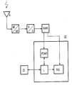
- the figure shows the basic circuit diagram of the exemplary embodiment.
- the Fig. Shows a receiving part of a digital mobile phone, consisting of an antenna A, which is followed by a frequency converter HF / NF.
- the incoming signal sequence is reduced to a frequency of 32 kHz.
- the tolerance is + 900 Hz.
- the low frequency signal is sampled at a rate of 512 kHz in a downstream analog / digital converter A / D, and the signal values are stored cyclically in a memory RAM of 512 bytes.
- the storage in the RAM memory is interrupted when the end of a PSW burst is detected.
- the memory RAM then contains the signal values of the last millisecond. Among these are the values of the PSW burst. Its exact position is determined by searching for the maximum of period values of a quasi-autocorrelation function.
- a timing element ZG is reset by the signal processor SP and the memory address of the last pulse signal sample is transferred to a carrier frequency generator FAS.
- the autocorrelation function acf of g (x) of a time function g (t) is defined by the following formula:
- the autocorrelation function acf of g (k) is defined by: where T is the sampling period. For a sine function of the period P it follows that the autocorrelation function increases and the period value acf (P) is greater than the partial period value acf (P / 16). For non-periodic functions with near correlation, for example for generally band-limited signals, the autocorrelation decreases in the statistical sense for the expected value. Superimposed white noise does not interfere with the autocorrelation.
- the period of the pulse signal is 16 ⁇ 0.45 samples.
- the maximum of the autocorrelation function and thus the end of the carrier frequency correction sequence lie between the sample value at which the period value is greater than the partial period value for the first time and that where this is not fulfilled for the first time. This maximum is determined by a logic circuit L.
- the two hysteresis constants h1 > 1 and h2 ⁇ 1 are introduced.
- the time index j takes account of the fact that the value of the quasi-autocorrelation function depends on the time of calculation.
- f is a window function.
- the quasi-autocorrelation function has approximately the same properties as the autocorrelation function.
- the carrier frequency generator FAS requires at least 247 values of the PSW burst for frequency adaptation.
- the theoretically maximum number of correct values available is 275.
- the identification method according to the invention provides 257 to 274 values depending on the signal / noise ratio.
Landscapes
- Physics & Mathematics (AREA)
- General Physics & Mathematics (AREA)
- Digital Transmission Methods That Use Modulated Carrier Waves (AREA)
- Radar Systems Or Details Thereof (AREA)
- Mobile Radio Communication Systems (AREA)
- Measuring Leads Or Probes (AREA)
- Selective Calling Equipment (AREA)
Abstract
Description
Die Erfindung betrifft ein Verfahren zur Identifizierung eines sinusförmigen Impulssignals bekannter Frequenz, das Teil einer frequenzmodulierten Signalfolge ist.The invention relates to a method for identifying a sinusoidal pulse signal of known frequency, which is part of a frequency-modulated signal sequence.
Für digitale Mobiltelefonnetze wird eine Trägerfrequenzgenauigkeit von 0,1 ppm gefordert. Diese Genauigkeit wäre aber nur durch ein Zeitnormal zu erreichen, das temperaturstabilisiert ist. Um eine Synchronisierung zu ermöglichen, wird von den Basisstationen des Netzes in periodischen Abständen ein "pure sine wave (PSW)-burst" mit einer entsprechenden Frequenz innerhalb eines Übertragungsrahmens gesendet. Im Empfangsteil der Mobilstation muß die Trägerfrequenz nun so eingestellt werden, daß sie von der Frequenz des PSW-bursts um höchstens 10⁻⁷ abweicht. Nach dem Einschalten des Mobiltelefons ist eine Erstsynchronisation auf den PSW-burst durchzuführen. Aufgrund von Unregelmäßigkeiten bei der Funkübertragung ist von Zeit zu Zeit auch eine Korrektursynchronisation durchzuführen, um den PSWburst sicher zu empfangen.A carrier frequency accuracy of 0.1 ppm is required for digital mobile phone networks. However, this accuracy could only be achieved with a time standard that is temperature-stabilized. In order to enable synchronization, the base stations of the network send a "pure sine wave (PSW) burst" with a corresponding frequency within a transmission frame at periodic intervals. In the receiving part of the mobile station, the carrier frequency must now be set so that it deviates from the frequency of the PSW burst by at most 10⁻⁷. After switching on the mobile phone, an initial synchronization to the PSW burst must be carried out. Due to irregularities in the radio transmission, correction synchronization must also be carried out from time to time in order to reliably receive the PSW burst.
Der Erfindung liegt die Aufgabe zugrunde, das sinusförmige Impulssignal des PSW-bursts aus einer Signalfolge zu erkennen.The invention has for its object to recognize the sinusoidal pulse signal of the PSW burst from a signal sequence.
Dies wird erfindungsgemäß dadurch erreicht, daß die Signalfolge digitalisiert wird und Signalwerte gebildet werden, daß laufend der Autokorrelationsfunktionwert der Signalfolge für eine Verschiebung um eine Periodenlänge des Signals als Periodenwert und der Autokorrelationsfunktionwert für eine Verschiebung um einen Abtastzeitraum als Periodenteilwert ermittelt werden und daß der Periodenwert mit dem Periodenteilwert verglichen wird, wobei der Beginn des Impulssignals identifiziert ist, wenn der Periodenwert größer als der Periodenteilwert wird.This is achieved according to the invention in that the signal sequence is digitized and signal values are formed, that the autocorrelation function value of the signal sequence for a shift by a period length of the signal as a period value and the autocorrelation function value for a shift by one sampling period are determined as a partial period value and that the period value is determined with is compared to the partial period value, the beginning of the pulse signal being identified when the period value becomes greater than the partial period value.
Vom erfindungsgemäßen Verfahren werden die unterschiedlichen Autokorrelationseigenschaften eines sinusförmigen und eines frequenzmodulierten Signals genutzt. Die Autokorrelationsfunktion einer Zeitfunktion nimmt bei modulierten (breitbandigen) Signalen mit wachsendem Variablenwert ab. Beim periodischen Signal ist die Funktion ebenfalls periodisch, wobei die Periode gleich der Periode des Ausgangssignals ist.The different autocorrelation properties of a sinusoidal and a frequency-modulated signal are used by the method according to the invention. The autocorrelation function of a time function decreases with modulated (broadband) signals with increasing variable value. With the periodic signal, the function is also periodic, the period being equal to the period of the output signal.
Zur besseren Anpassung des erfindungsgemäßen Verfahrens an unterschiedliche Realisierungen ist es vorteilhaft, daß die Signalwerte in einem Speicher zyklisch abgespeichert werden und die Abspeicherung nach dem Beginn des Impulssignals mit dem Absinken des Periodenwertes unter den Periodenteilwert unterbrochen wird und daß aus dem größten Periodenwert die Lage der Abtastwerte des Impulssignals ermittelt und ein Zeitglied rückgesetzt wird. So enthält der Speicher die Abtastwerte der zuletzt abgelaufenen Zeitspanne, innerhalb der ein PSW-burst gesendet wurde. Seine genaue Lage kann unabhängig vom Empfang der weiteren Signalfolge ermittelt werden.To better adapt the method according to the invention to different implementations, it is advantageous that the signal values are stored cyclically in a memory and the storage is interrupted after the beginning of the pulse signal when the period value drops below the partial period value and that the position of the sample values is from the largest period value of the pulse signal is determined and a timer is reset. The memory thus contains the samples of the last elapsed period within which a PSW burst was sent. Its exact position can be determined independently of the reception of the further signal sequence.
Um nur eine möglichst kurze Signalfolge speichern zu müssen, muß die Erstsynchronisation in Echtzeit erfolgen. Daher entfallen weitgehend konventionelle Methoden digitaler Filterung. Zur schnellen Identifizierung des Impulssignals ist es vorteilhaft, daß die Autokorrelationsfunktion durch Ergänzung mit einer exponentiellen Fensterfunktion verallgemeinert und zur Ermittlung der Perioden- und Periodenteilwerte eine Rekursionsformel verwendet wird.In order to only have to store a signal sequence that is as short as possible, the first synchronization must take place in real time. Therefore, conventional methods of digital filtering are largely eliminated. For quick identification of the pulse signal, it is advantageous that the auto-correlation function is generalized by supplementing it with an exponential window function and a recursion formula is used to determine the period and partial period values.
Es werden bereits verschiedene Verfahren und Vorrichtungen zur Trägerfrequenzkorrektur für digitale Mobiltelefone mit Hilfe des PWS-bursts vorgeschlagen. Der Erfindung liegt daher weiter die Aufgabe zugrunde, daß Identifizierungsverfahren mit vorgeschlagenen Vorrichtungen kombinieren zu können.Various methods and devices for carrier frequency correction for digital mobile telephones with the aid of the PWS burst have already been proposed. The invention is therefore based on the object of being able to combine identification methods with proposed devices.
Dies wird durch eine Vorrichtung zur Identifizierung eines sinusförmigen Impulssignals bekannter Frequenz, aus dem eine Trägerfrequenzkorrektur für digitale Mobiltelefone ableitbar ist, wobei im Empfangsteil des Mobiltelefons ein Frequenzumsetzer vorhanden ist, dem ein Analog/Digital-Wandler und ein Signalprozessor nachgeordnet ist, erreicht, die dadurch gekennzeichnet ist, daß der Signalprozessor einen Impulssignaldetektor und einen Trägerfrequenzgenerator enthält, daß ein Speicher zwischen den Analog/Digital-Wandler und den Signalprozessor geschaltet ist und mit Prozessoreingängen des Impulssignaldetektors und des Trägerfrequenzgenerators verbunden ist und daß ein rücksetzbares Zeitglied mit dem Signalprozessor verbunden ist.This is achieved by a device for identifying a sinusoidal pulse signal of known frequency, from which a carrier frequency correction for digital mobile telephones can be derived, a frequency converter being present in the receiving part of the mobile telephone, which is followed by an analog / digital converter and a signal processor, which thereby characterized in that the signal processor includes a pulse signal detector and a carrier frequency generator, that a memory is connected between the analog / digital converter and the signal processor and is connected to processor inputs of the pulse signal detector and the carrier frequency generator and that a resettable timer is connected to the signal processor.
Die Erfindung wird anhand eines Ausführungsbeispieles und einer Figur näher erläutert. Die Figur zeigt das Prinzipschaltbild des Ausführungsbeispieles.The invention is explained in more detail using an exemplary embodiment and a figure. The figure shows the basic circuit diagram of the exemplary embodiment.
Die Fig. zeigt einen Empfangsteil eines digitalen Mobiltelefons, bestehend aus einer Antenne A, der ein Frequenzumsetzer HF/NF nachgeordnet ist. Die ankommende Signalfolge wird auf eine Frequenz von 32 kHz heruntergesetzt. Die Toleranz beträgt + 900 Hz. Das Niederfrequenzsignal wird mit einer Rate von 512 kHz in einem nachgeschalteten Analog/Digital-wandler A/D abgetastet, und die Signalwerte werden in einen Speicher RAM von 512 bytes zyklisch abgelegt. Die Abspeicherung in den Speicher RAM wird unterbrochen, wenn das Ende eines PSW-bursts detektiert wird. Der Speicher RAM enthält dann die Signalwerte der letzten Millisekunde. Unter diesen befinden sich auch die Werte des PSW-bursts. Seine genaue Lage wird durch das Aufsuchen des Maximums von Periodenwerten einer Quasi-Autokorrelationsfunktion ermittelt. Nachdem der PSW-burst lokalisiert ist, wird ein Zeitglied ZG vom Signalprozessor SP zurückgesetzt und die Speicheradresse des letzten Impulssignals-Abtastwertes an einen Trägerfrequenzgenerator FAS übergeben.The Fig. Shows a receiving part of a digital mobile phone, consisting of an antenna A, which is followed by a frequency converter HF / NF. The incoming signal sequence is reduced to a frequency of 32 kHz. The tolerance is + 900 Hz. The low frequency signal is sampled at a rate of 512 kHz in a downstream analog / digital converter A / D, and the signal values are stored cyclically in a memory RAM of 512 bytes. The storage in the RAM memory is interrupted when the end of a PSW burst is detected. The memory RAM then contains the signal values of the last millisecond. Among these are the values of the PSW burst. Its exact position is determined by searching for the maximum of period values of a quasi-autocorrelation function. After the PSW burst is located, a timing element ZG is reset by the signal processor SP and the memory address of the last pulse signal sample is transferred to a carrier frequency generator FAS.
Die Autokorrelationsfunktion acf von g(x) einer Zeitfunktion g(t) ist durch die folgende Formel definiert: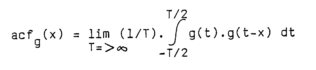
Für die Abtastwerte der Zeitfunktion g(t) ist die Autokorrelationsfunktion acf von g(k) definiert durch:

wobei T die Abtastperiode ist. Für eine Sinusfunktion der Periode P folgt daraus, daß die Autokorrelationsfunktion anwächst und der Periodenwert acf(P) größer als der Periodenteilwert acf(P/l6) ist. Für nichtperiodische Funktionen mit Nahkorrelation, z.B. für allgemein bandbegrenzte Signale, nimmt die Autokorrelation im statistischen Sinn für den Erwartungswert ab. Überlagertes weißes Rauschen stellt keine Störung der Autokorrelation dar.For the samples of the time function g (t), the autocorrelation function acf of g (k) is defined by:
where T is the sampling period. For a sine function of the period P it follows that the autocorrelation function increases and the period value acf (P) is greater than the partial period value acf (P / 16). For non-periodic functions with near correlation, for example for generally band-limited signals, the autocorrelation decreases in the statistical sense for the expected value. Superimposed white noise does not interfere with the autocorrelation.
Entsprechend der Relation zwischen der Abtastrate des Analog/ Digital-Wandlers A/D und der Frequenz des Impulssignals beträgt die Periode des Impulssignals 16 ± 0,45 Abtastungen. Zwischen dem Abtastwert, bei dem erstmals der Periodenwert größer als der Periodenteilwert ist und jenem, wo dies erstmals wieder nicht erfüllt ist, liegt das Maximum der Autokorrelationsfunktion und damit das Ende der Trägerfrequenz-Korrekturfolge. Dieses Maximum wird von einer Logikschaltung L ermittelt. Um die Stabilität des Algorithmus zu verbessern, werden die beiden Hysteresekonstanten h1> 1 und h2<1 eingeführt.Corresponding to the relation between the sampling rate of the analog / digital converter A / D and the frequency of the pulse signal, the period of the pulse signal is 16 ± 0.45 samples. The maximum of the autocorrelation function and thus the end of the carrier frequency correction sequence lie between the sample value at which the period value is greater than the partial period value for the first time and that where this is not fulfilled for the first time. This maximum is determined by a logic circuit L. To improve the stability of the algorithm, the two hysteresis constants h1 > 1 and h2 <1 are introduced.
Wegen der Abtastrate von 512 kHz bleibt zwischen zwei aufeinanderfolgenden Abtastungen lediglich eine Rechenzeit von 1,95 µs. Das sind bei den schnellsten derzeit verfügbaren Signalprozessoren SP 19 Arbeitszyklen. Daher läßt sich dieBecause of the sampling rate of 512 kHz, there is only a computing time of 1.95 µs between two successive samples. With the fastest SP 19 signal processors currently available, this is 19 working cycles. Therefore, the
Berechnung der Autokorrelationswerte nicht bewerkstelligen. Aus einer Verallgemeinerung der Autokorrelationsfunktion ist aber eine Quasi-Autokorrelationsfunktion zu gewinnen. Diese bietet die Möglichkeit einer rekursiven Berechnung. Die Definition der Quasi-Autokorrelationsfunktion aqf für zeitdiskrete Signale g(nT) lautet: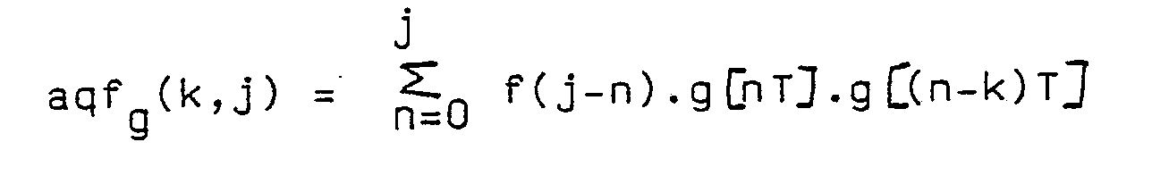
Der Zeitindex j trägt der Tatsache Rechnung, daß der Wert der Quasi-Autokorrelationsfunktion vom Berechnungszeitpunkt abhängt. f ist eine Fensterfunktion. Bei der Verwendung einer exponentiellen Fensterfunktion ergibt sich
Die Quasi-Autokorrelationsfunktion hat qualitativ etwa die gleichen Eigenschaften wie die Autokorrelationsfunktion. Der Trägerfrequenzgenerator FAS benötigt mindestens 247 Werte des PSW-bursts zur Frequenzanpassung. Die theoretisch maximal erhältliche Anzahl korrekter Werte beträgt 275. Durch das erfindungsgemäße Identifizierungsverfahren werden je nach Signal/Rausch-Verhältnis 257 bis 274 Werte zur Verfügung gestellt.In terms of quality, the quasi-autocorrelation function has approximately the same properties as the autocorrelation function. The carrier frequency generator FAS requires at least 247 values of the PSW burst for frequency adaptation. The theoretically maximum number of correct values available is 275. The identification method according to the invention provides 257 to 274 values depending on the signal / noise ratio.
Claims (4)
Applications Claiming Priority (2)
| Application Number | Priority Date | Filing Date | Title |
|---|---|---|---|
| AT0271989A ATA271989A (en) | 1989-11-29 | 1989-11-29 | DEVICE FOR IDENTIFYING A SINUS-SHAPED IMPULSE SIGNAL |
| AT2719/89 | 1989-11-29 |
Publications (3)
| Publication Number | Publication Date |
|---|---|
| EP0429991A2 true EP0429991A2 (en) | 1991-06-05 |
| EP0429991A3 EP0429991A3 (en) | 1992-11-19 |
| EP0429991B1 EP0429991B1 (en) | 1995-07-12 |
Family
ID=3539223
Family Applications (1)
| Application Number | Title | Priority Date | Filing Date |
|---|---|---|---|
| EP90121971A Expired - Lifetime EP0429991B1 (en) | 1989-11-29 | 1990-11-16 | Method and apparatus for identifying a sine pulse signal |
Country Status (3)
| Country | Link |
|---|---|
| EP (1) | EP0429991B1 (en) |
| AT (2) | ATA271989A (en) |
| DE (1) | DE59009398D1 (en) |
Cited By (2)
| Publication number | Priority date | Publication date | Assignee | Title |
|---|---|---|---|---|
| EP1237319A1 (en) * | 2001-02-26 | 2002-09-04 | Juniper Networks, Inc. | Methods and apparatus for efficient and accurate coarse timing synchronization in burst demodulators |
| KR100436166B1 (en) * | 2001-12-27 | 2004-06-12 | 한국전자통신연구원 | Apparatus for detecting burst signal and method thereof |
Citations (3)
| Publication number | Priority date | Publication date | Assignee | Title |
|---|---|---|---|---|
| US4038540A (en) * | 1976-04-19 | 1977-07-26 | Honeywell Inc. | Quadrature correlation pulse detector |
| GB2181548A (en) * | 1985-10-07 | 1987-04-23 | Honeywell Inc | Pulse detection using correlation |
| US4775951A (en) * | 1982-12-20 | 1988-10-04 | Computer Basic Technology Research Association | Correlation function computing device |
-
1989
- 1989-11-29 AT AT0271989A patent/ATA271989A/en not_active Application Discontinuation
-
1990
- 1990-11-16 AT AT90121971T patent/ATE125093T1/en active
- 1990-11-16 DE DE59009398T patent/DE59009398D1/en not_active Expired - Fee Related
- 1990-11-16 EP EP90121971A patent/EP0429991B1/en not_active Expired - Lifetime
Patent Citations (3)
| Publication number | Priority date | Publication date | Assignee | Title |
|---|---|---|---|---|
| US4038540A (en) * | 1976-04-19 | 1977-07-26 | Honeywell Inc. | Quadrature correlation pulse detector |
| US4775951A (en) * | 1982-12-20 | 1988-10-04 | Computer Basic Technology Research Association | Correlation function computing device |
| GB2181548A (en) * | 1985-10-07 | 1987-04-23 | Honeywell Inc | Pulse detection using correlation |
Cited By (6)
| Publication number | Priority date | Publication date | Assignee | Title |
|---|---|---|---|---|
| EP1237319A1 (en) * | 2001-02-26 | 2002-09-04 | Juniper Networks, Inc. | Methods and apparatus for efficient and accurate coarse timing synchronization in burst demodulators |
| US7154967B2 (en) | 2001-02-26 | 2006-12-26 | Juniper Networks, Inc. | Methods and apparatus for efficient and accurate coarse timing synchronization in burst demodulators |
| US7616717B2 (en) | 2001-02-26 | 2009-11-10 | Juniper Networks, Inc. | Coarse timing synchronization |
| US7957494B2 (en) | 2001-02-26 | 2011-06-07 | Juniper Networks, Inc. | Coarse timing synchronization |
| US8451958B2 (en) | 2001-02-26 | 2013-05-28 | Juniper Networks, Inc. | Coarse time synchronization |
| KR100436166B1 (en) * | 2001-12-27 | 2004-06-12 | 한국전자통신연구원 | Apparatus for detecting burst signal and method thereof |
Also Published As
| Publication number | Publication date |
|---|---|
| ATA271989A (en) | 1992-10-15 |
| EP0429991A3 (en) | 1992-11-19 |
| DE59009398D1 (en) | 1995-08-17 |
| EP0429991B1 (en) | 1995-07-12 |
| ATE125093T1 (en) | 1995-07-15 |
Similar Documents
| Publication | Publication Date | Title |
|---|---|---|
| DE19600404C2 (en) | Speech detector for detecting the presence of speech | |
| AT396724B (en) | METHOD AND DEVICE FOR DEMODULATING HIGH FREQUENCY MODULATED SIGNALS BY MEANS OF DIGITAL FILTERS AND DIGITAL DEMODULATORS, AND USE OF THE METHOD IN A REMOTE CONTROL RECEIVER | |
| DE69535191T2 (en) | METHOD AND DEVICE FOR REDUCING NOISE GENERATED DATA ERRORS USING INTERFERENCE EFFECT | |
| DE3233637A1 (en) | DEVICE FOR DETERMINING THE DURATION OF VOICE OR SOUND SIGNALS | |
| DE2034623A1 (en) | Method and apparatus for the payment of speech signals in the presence of noise | |
| EP0304799A2 (en) | Apparatus for demodulating a biphase signal | |
| EP0634842A2 (en) | Method and apparatus for disturbance resistant bidirectional information transmission over power distribution networks | |
| DE2948676C2 (en) | Multi-frequency character detector | |
| DE3732287A1 (en) | METHOD AND CIRCUIT ARRANGEMENT FOR DERIVING THE WORD CLOCK OF A PULSE POSITION-MODULATED SIGNAL | |
| EP0429991B1 (en) | Method and apparatus for identifying a sine pulse signal | |
| DE3516007A1 (en) | MONOLITHICALLY INTEGRATED TELEPHONE CIRCUIT WITH CONTROL SIGNAL GENERATOR FOR CHARGE INDICATORS | |
| DE69629643T2 (en) | TRANSMISSION SYSTEM WITH IMPROVED SOUND RECOGNITION | |
| DE2635856A1 (en) | METHOD AND CIRCUIT ARRANGEMENTS FOR CARRIER DETECTION | |
| CH651978A5 (en) | Device with a hybrid circuit for digital duplex transmission | |
| EP1490962B1 (en) | Demodulation of a digitally frequency modulated analogue received signal by evaluation of the time difference between the null transitions | |
| DE2915834A1 (en) | DEVICE FOR MONITORING THE OPERATING BEHAVIOR OF A TRANSMITTER | |
| EP0445384B1 (en) | Method and circuit arrangement for threshold control | |
| EP0924911B1 (en) | Multicarrier method of transmission on power distribution networks | |
| DE10000008A1 (en) | Process for low-cost signal, tone and phase change detection | |
| EP0691755B1 (en) | Method and apparatus for digital signal synthesis and processing for frequency hopping spread spectrum systems | |
| DE2723570B2 (en) | Signal receiver | |
| DE3915779A1 (en) | Phase-shift keying signals identification system - using evaluation of statistical distribution of phase difference values obtained from sampled phase values of received signal | |
| DE69629641T2 (en) | TRANSMISSION SYSTEM WITH IMPROVED SOUND RECOGNITION | |
| AT399434B (en) | Method and apparatus for generating an oscillation having a transmission frequency | |
| EP0671822B1 (en) | Method and apparatus for digital signal synthesis and processing in a full-duplex data transmission system |
Legal Events
| Date | Code | Title | Description |
|---|---|---|---|
| PUAI | Public reference made under article 153(3) epc to a published international application that has entered the european phase |
Free format text: ORIGINAL CODE: 0009012 |
|
| 17P | Request for examination filed |
Effective date: 19901220 |
|
| AK | Designated contracting states |
Kind code of ref document: A2 Designated state(s): AT BE CH DE DK FR GB LI NL SE |
|
| PUAL | Search report despatched |
Free format text: ORIGINAL CODE: 0009013 |
|
| AK | Designated contracting states |
Kind code of ref document: A3 Designated state(s): AT BE CH DE DK FR GB LI NL SE |
|
| 17Q | First examination report despatched |
Effective date: 19941129 |
|
| GRAA | (expected) grant |
Free format text: ORIGINAL CODE: 0009210 |
|
| AK | Designated contracting states |
Kind code of ref document: B1 Designated state(s): AT BE CH DE DK FR GB LI NL SE |
|
| PG25 | Lapsed in a contracting state [announced via postgrant information from national office to epo] |
Ref country code: NL Free format text: LAPSE BECAUSE OF NON-PAYMENT OF DUE FEES Effective date: 19950712 Ref country code: GB Effective date: 19950712 Ref country code: FR Effective date: 19950712 Ref country code: DK Effective date: 19950712 Ref country code: BE Effective date: 19950712 |
|
| REF | Corresponds to: |
Ref document number: 125093 Country of ref document: AT Date of ref document: 19950715 Kind code of ref document: T |
|
| REF | Corresponds to: |
Ref document number: 59009398 Country of ref document: DE Date of ref document: 19950817 |
|
| PG25 | Lapsed in a contracting state [announced via postgrant information from national office to epo] |
Ref country code: SE Effective date: 19951012 |
|
| PG25 | Lapsed in a contracting state [announced via postgrant information from national office to epo] |
Ref country code: AT Effective date: 19951116 |
|
| PG25 | Lapsed in a contracting state [announced via postgrant information from national office to epo] |
Ref country code: LI Effective date: 19951130 Ref country code: CH Effective date: 19951130 |
|
| EN | Fr: translation not filed | ||
| NLV1 | Nl: lapsed or annulled due to failure to fulfill the requirements of art. 29p and 29m of the patents act | ||
| GBV | Gb: ep patent (uk) treated as always having been void in accordance with gb section 77(7)/1977 [no translation filed] |
Effective date: 19950712 |
|
| PGFP | Annual fee paid to national office [announced via postgrant information from national office to epo] |
Ref country code: DE Payment date: 19960119 Year of fee payment: 6 |
|
| PLBE | No opposition filed within time limit |
Free format text: ORIGINAL CODE: 0009261 |
|
| STAA | Information on the status of an ep patent application or granted ep patent |
Free format text: STATUS: NO OPPOSITION FILED WITHIN TIME LIMIT |
|
| 26N | No opposition filed | ||
| REG | Reference to a national code |
Ref country code: CH Ref legal event code: PL |
|
| PG25 | Lapsed in a contracting state [announced via postgrant information from national office to epo] |
Ref country code: DE Effective date: 19970801 |