EP0429201A2 - High efficiency image data transfer networks and methods - Google Patents
High efficiency image data transfer networks and methods Download PDFInfo
- Publication number
- EP0429201A2 EP0429201A2 EP90311927A EP90311927A EP0429201A2 EP 0429201 A2 EP0429201 A2 EP 0429201A2 EP 90311927 A EP90311927 A EP 90311927A EP 90311927 A EP90311927 A EP 90311927A EP 0429201 A2 EP0429201 A2 EP 0429201A2
- Authority
- EP
- European Patent Office
- Prior art keywords
- data
- node
- bit
- nodes
- clocking
- Prior art date
- Legal status (The legal status is an assumption and is not a legal conclusion. Google has not performed a legal analysis and makes no representation as to the accuracy of the status listed.)
- Withdrawn
Links
Images


Classifications
-
- H—ELECTRICITY
- H04—ELECTRIC COMMUNICATION TECHNIQUE
- H04N—PICTORIAL COMMUNICATION, e.g. TELEVISION
- H04N1/00—Scanning, transmission or reproduction of documents or the like, e.g. facsimile transmission; Details thereof
- H04N1/32—Circuits or arrangements for control or supervision between transmitter and receiver or between image input and image output device, e.g. between a still-image camera and its memory or between a still-image camera and a printer device
- H04N1/32358—Circuits or arrangements for control or supervision between transmitter and receiver or between image input and image output device, e.g. between a still-image camera and its memory or between a still-image camera and a printer device using picture signal storage, e.g. at transmitter
- H04N1/32363—Circuits or arrangements for control or supervision between transmitter and receiver or between image input and image output device, e.g. between a still-image camera and its memory or between a still-image camera and a printer device using picture signal storage, e.g. at transmitter at the transmitter or at the receiver
- H04N1/32368—Functions of a still picture terminal memory associated with transmission
-
- H—ELECTRICITY
- H04—ELECTRIC COMMUNICATION TECHNIQUE
- H04N—PICTORIAL COMMUNICATION, e.g. TELEVISION
- H04N1/00—Scanning, transmission or reproduction of documents or the like, e.g. facsimile transmission; Details thereof
- H04N1/00095—Systems or arrangements for the transmission of the picture signal
- H04N1/001—Systems or arrangements for the transmission of the picture signal specially adapted for transmission via digital wireline networks
-
- H—ELECTRICITY
- H04—ELECTRIC COMMUNICATION TECHNIQUE
- H04N—PICTORIAL COMMUNICATION, e.g. TELEVISION
- H04N1/00—Scanning, transmission or reproduction of documents or the like, e.g. facsimile transmission; Details thereof
- H04N1/21—Intermediate information storage
- H04N1/2166—Intermediate information storage for mass storage, e.g. in document filing systems
- H04N1/2179—Interfaces allowing access to a plurality of users, e.g. connection to electronic image libraries
-
- H—ELECTRICITY
- H04—ELECTRIC COMMUNICATION TECHNIQUE
- H04N—PICTORIAL COMMUNICATION, e.g. TELEVISION
- H04N1/00—Scanning, transmission or reproduction of documents or the like, e.g. facsimile transmission; Details thereof
- H04N1/32—Circuits or arrangements for control or supervision between transmitter and receiver or between image input and image output device, e.g. between a still-image camera and its memory or between a still-image camera and a printer device
- H04N1/32358—Circuits or arrangements for control or supervision between transmitter and receiver or between image input and image output device, e.g. between a still-image camera and its memory or between a still-image camera and a printer device using picture signal storage, e.g. at transmitter
- H04N1/32363—Circuits or arrangements for control or supervision between transmitter and receiver or between image input and image output device, e.g. between a still-image camera and its memory or between a still-image camera and a printer device using picture signal storage, e.g. at transmitter at the transmitter or at the receiver
- H04N1/32379—Functions of a still picture terminal memory associated with reception
-
- H—ELECTRICITY
- H04—ELECTRIC COMMUNICATION TECHNIQUE
- H04N—PICTORIAL COMMUNICATION, e.g. TELEVISION
- H04N2201/00—Indexing scheme relating to scanning, transmission or reproduction of documents or the like, and to details thereof
- H04N2201/32—Circuits or arrangements for control or supervision between transmitter and receiver or between image input and image output device, e.g. between a still-image camera and its memory or between a still-image camera and a printer device
- H04N2201/3285—Circuits or arrangements for control or supervision between transmitter and receiver or between image input and image output device, e.g. between a still-image camera and its memory or between a still-image camera and a printer device using picture signal storage, e.g. at transmitter
- H04N2201/329—Storage of less than a complete document page or image frame
Definitions
- the invention relates to high efficiency image data transfer networks and methods. It finds particular application in conjunction with the transfer of image data among electronic medical diagnostic equipments such as computed tomography (CT) scanners, magnetic resonance imagers, digital x-ray equipments, and other equipments that generate, process or display digital image information.
- CT computed tomography
- magnetic resonance imagers magnetic resonance imagers
- digital x-ray equipments and other equipments that generate, process or display digital image information.
- the invention will also find application in other areas, particularly where large blocks of data are to be transferred.
- Various schemes have been developed for sharing the common bus, such as frequency or time division multiplexing. Most commonly, an asynchronous time division protocol is utilized.
- data is collected in the buffers of a file server from one or more sources. This data is recopied into a transport protocol hardware which adds its appropriate headers or other information. The data is copied from the buffers of the transport protocol to buffers of a queuing and multiplexing level, which again adds headers and other information to the data. The queuing and multiplexing level also oversees placing the data on the bus media in an efficient and fair way by the data link hardware. At the receive end, the data is again recopied from buffer to buffer as it is moved through the same layers, doubling the overhead.
- a data transfer network comprising: a network media extending between each of a plurality of nodes; means for generating image representations connected with one of said nodes, each image representation including a relatively large block of image data; means for processing image data connected to another of said nodes; a first of said nodes including: buffer means for storing each of a plurality of image data packets, which taken together comprise an image data block, first data link means for transmitting each data packet on said network media, a second of the nodes including: second data link means for receiving the data packet from the network media; receiver memory means for storing at least one image data block, characterised in that: said first node includes a transmit data management means for controlling the transfer of data between said buffer means and said data link means and said second node includes receive data management means for transferring image data packets from said second data link means to said receiver memory means, and, receiver memory address control means for monitoring addresses of said receiver memory means at which previously received image data packets are stored and providing receiver memory addresses
- a data transfer network comprising: a network media extending between each of a plurality of nodes; means for generating and processing large blocks of data connected with a plurality of said nodes; a first of said nodes including: data link means for receiving a plurality of data packets which taken together comprise one of the large blocks of data from the network media; and memory means for storing the large block of data; characterised in that said node further includes receive data management means for transferring each of the received data packets from said data link means to the memory means; and memory address control means for monitoring addresses of the memory means where previously received data packets are stored and for providing memory addresses for each subsequently received data packet.
- a data transfer network comprising: a network media extending between a plurality of nodes; means for processing large blocks of data connected with at least some of the nodes; a first of the nodes transmitting data to a second of the nodes, characterised in that said second node includes: an elasticity buffer into which data from the first node is clocked at a clocking rate of the first node and out of which the data is clocked at a clocking rate of the second node, said elasticity buffer having a sufficient storage capacity to accommodate variable numbers of bits of data attributable to differences in the clocking rates of the first and second nodes.
- a data transfer network comprising: a network media on which data is passed in n-bit format, where n is an integer, the network media extending between a plurality of nodes; means connected with said nodes for processing and handling blocks of m-bit format data, where m is an integer that is an even multiple of n; at least one of said nodes including: data link means for receiving n-bit data from said network media, m/n serially connected n-bit buffers, clocking means for clocking n-bit data from said data link means serially through the n-bit buffers until said buffers are filled and, when said buffers are filled concurrently clocking said buffers to pass an m-bit format word to the associated one of the data processing and handling means.
- a data transfer network comprising: a network media extending between each of a plurality of nodes; means for processing and handling data connected with the nodes; characterised in that a first of the nodes includes: means for storing a plurality of data packets, each packet being designated for transmission to one of the other receiving nodes and being assigned a relative transmission priority, each designated receiving node having a statistical probability of availability to receive a transmitted data packet; data link means operatively connected with said storing means and said network media for transmitting data packets serially on said network media; data packet order determining means for determining an order in which said data link means transmits the stored data packets on said network media in accordance with a weighted combination of the assigned priority of each packet and the statistical availability probability of the corresponding designated receiving node.
- a method of transferring data among a plurality of nodes interconnected by a network media comprising: at a first of the nodes, storing at least one large block of image data, serially transmitting smaller data packets of the large data block on the network media to a second node and at a second node, serially receiving said data packets from the network media and storing each received packet in a memory; characterised in that said method includes the step of at said second node, keeping track of where packets corresponding to each data block being received packet by packet, are stored and directing each subsequently received packet to appropriate addresses in the memory.
- a method of transferring data among a plurality of nodes which are interconnected by a plurality of nodes, the nodes being clocked at clocking rates which are close to each other but not exactly the same characterised in that said method comprises the steps of: transmitting data from a first of the nodes at a first clocking rate; at a second of the nodes, clocking the data into a buffer at the first clocking rate and clocking the data out of the buffer at a second clocking rate at which the second node is clocked.
- a method of transferring data between a plurality of devices that proces data in m-bit format on a network media that transmits data in an n-bit format characterised in that the method comprises the steps of: clocking n-bit data serially through a plurality of n-bit buffers: when said n-blt buffers are filled, clocking said n-blt buffers concurrently to clock out an m-blt format word.
- a method of transferring packets of data among a plurality of nodes that are interconnected by a network media comprising the steps of: at one of the nodes, storing a plurality of packets of data, each of which is waiting for transmission on the media, to a designated one of said plurality of nodes, each packet having a designated priority and each designated node having a statistical probability of availability to receive a packet; and characterised in that said method comprises the step of serially transmitting the awaiting packets on the network media in an order established by a combination of both the relative priority of each packet and the statistical availability of the corresponding designated node.
- a method of transferring large packets of data and small data transmissions among a plurality of nodes that are interconnected in a ring by a network media characterised in that only a node which has a token is permitted to place a new data packet or a data transmission on the network media and characterised in that said method comprises the steps of: a first node, which has the token, intermittently transmitting new packets of data on the network media; between transmission of the data packets, said first node with the token passing a restricted token around the ring, said restricted token permitting a node possessing said restricted token to transmit smaller data transmissions over the network media but not the large data packets; as the restricted token is passed around the ring, a second node seizing the restricted token and transmitting a smaller data transmission to a third node.
- An advantage of the present invention is that it more efficiently transfers image data or other large packets of data.
- Another advantage of the present invention is that it is flexible and facilitates the adding of additional nodes to the network.
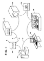
- an image data transfer network A interconnects a plurality of stations or nodes B.
- the data transfer network is composed of a plurality of lengths of fiber optic cable 10 for transmitting data encoded light in a single direction from node to node.
- other transmission media may also be utilized as is known in the art.
- Each node retransmits the received information on the next length of fiber optic cable until the message has moved to each of the nodes and returned around the circle to the originating node.
- a plurality of scanners such as a computed tomography (CT) scanner 20, a magnetic resonance imager 22, and a laser, digital x-ray, nuclear camera, or other digital imager 24 may be used.
- CT computed tomography
- the imagers at these nodes non-invasively examine a patient and generate image data indicative thereof.
- the imagers may process the image data at each station and transmit completed images or may convey the raw image data along the network to another node which is interconnected with an appropriately programmed computer for processing the data.
- An archiving computer memory means 26 stores a large plurality of images. Because images typically contain about 4 megabytes of data, the archiving memory means may typically have a plurality of hard disks.
- nodes of the network are connected with operator control stations 28 from which the operator may control a scan, may view a selected image, operate on the selected image or images with various enhancement routines to improve their diagnostic value, and the like.
- the operator terminals may be interconnected with a hard copy apparatus for converting the electronically displayed diagnostic images into hard copy images on film, paper, or the like.
- other nodes of the system may be connected with a more simple physician viewing station 30 at which a physician or radiologist may call up and view selected images for diagnostic purposes.
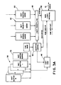
- each station node typically has both transmit and receive portions.
- a transmitting node portion associated with the request receiving station e.g. one of the CT scanners 20
- the image data is transferred through a data base means 34 to a file server 36.
- the file server typically receives and store an image in its transmit buffers 38.
- Smaller packets of the image data are transferred through a transport protocol means 40 without recopying to queuing buffers 42 of a queuing and multiplexing means 44 under the control of a transmit data management means 46.
- the size of the packets is matched to the size of the queuing buffers.
- the queuing buffers are preferably as large as possible but are presently 4 kilobytes due to an unavailability of larger suitable buffer hardware.
- the data in the queue buffers 42 may include high priority data in the priority buffer and lower priority data in a normal queue buffer.
- a transmit ordering means 48 controls the order in which the packets of data in queue buffers 42 are transferred.
- the weighting factors may be predetermined and assigned based on iterative adjustment, practical experience, or computer implemented system optimizing procedures.
- an adaptive control means 50 monitors the efficiency of the transmission of the data network and iteratively adjusts the weighting factors to improve and maintain the optimum efficiency with changing transmission patterns.
- the data management means 46 adds appropriate header information to the data as it is moved from the file server buffers 38 to the queuing buffers 42.
- This header information includes a start delimiter, a destination node address, the source or transmitting node address, the 4 kilobyte data or packet field or information, an end delimiter, and a frame status.
- a data link means 52 receives tbe packet data from the designated queue buffer and the header information from the data management means 46 to formulate a message.
- the message is applied to the network media 10.
- the data message moves to the next node in the unidirectional data transmission direction where it is received and retransmitted. This receive and retransmit procedure continues until the receiving node recognizes its address in the header.
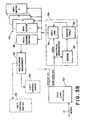
- a data link means 52′ at the receiving node retrieves the message and transmits it to a demultiplexing means 54.
- a receive data management means 56 receives the data packet and a decoding means 68 receives the multiplexing means applied headers.
- the header information is utilized to address a look-up table 60 which looks up the appropriate address for buffers 62 of a file server 64.
- the headers are used to determine to which of a potential plurality of images each data packet corresponds. For a given designated image, the data packets are received in order. Thus, each received 4 kilobyte field or packet of data is loaded into the receiving buffer memory means 62 in the locations immediately following the preceding data packet of the same image.
- the buffer table means 60 keeps track of the appropriate starting address for each received packet or the ending address for the precedingly received packet.
- the received data management means 56 transfers the data packet to the receive buffer memory means 62 at the addresses designated by the buffer table means 60. In this manner, the data is transferred directly to the receive buffer memories of the file server 64 without the inefficiency of recopying by the demultiplexing means 54 or a transport protocol means 66.
- a data base meanS 70 transfers the 4 megabyte images to a processor or other portions of the system 72 at the receiving node.
- Equation 1 Various techniques may be utilized for adjusting the weighting factors of Equation 1.
- the queries and the original messages return to the transmitting node with an indication whether they were accepted by the receiving node.
- a statistical table may be kept of the number of times the query or message comes back with an indication that each receiving node is busy. This information enables the transmit adaptive control means 50 to adjust the selection of packets from the buffers 42 to pick the one which has the best prospects for being received.
- a multiplexing management system 74 receives information from a receive control buffer 76 concerning which image or other data is requested.
- the multiplex management means 74 may be connected with the data link means 52 for placing image data requests on the network A to be communicated to the station that has the requested information. These image data requests are received by the data link 52 of the transmitting buffer and communicated to the appropriate file server and multiplexing means controls 78, 80. Alternately, the requests for data can be transmitted by a separate data channel.
- the request is communicated to the file server transmit buffer control means 78 for controlling which image representation is to be moved in packets to the queue buffers 42 for transmission to the requesting station.
- Each information request includes priority information, which is conveyed to the multiplexor control 80 to provide the priority input regarding the order or transmission determination.
- a token ring type protocol is utilized in which messages are passed downstream from node to node around the ring.
- a node detects its own address as the destination address, it copies the data packet into its buffers as described above.
- the transmitting node strips the message from the ring and passes the token to the next node.
- the token is passed after each transmission to assure equal access to the network by all nodes.
- the token is a control signal that is used to grant a node the privilege to transmit on the ring.
- a node that wishes to transmit captures the token and removes it from the ring.
- the transmitting node first sends a query to determine whether the destination node can accept the information packet.
- a positive acknowledgement is generally returned by the addressed receiving node in the form of trailing indicators that have been modified by the destination to designate its status.
- the transmitting node now formulates a message including headers as described above and a data packet - in the preferred embodiment, 4 kilobytes. The message is passed from node to node and copied by the destination node if it is available to receive.
- the destination node modifies the header information or trailing indicators to indicate whether or not it copied the information.
- the message When the message is returned to the transmitting node, it removes it from the network and notes whether or not the receiving node copied the information. If the information was copied, the transmitting node readies its next packet of information; if the information was not copied, the transmitting mode prepares to retransmit the packet again. In either instance, the token is passed.
- the protocol for controlling each node can be described as two separate state machines that communicate with each other - the receiver state and the transmitter state. Symbols within each packet arrive at the receiver asynchronously to the state of the transmitter. This requires that the receiver receive packets concurrently with other actions which may be being undertaken by the transmitter.
- the transmitter is informed of various receiver events, such as the reception of a claim packet. Notification occurs through signals that are passed from one state machine to the other. Global signals are used for events that cause responses from both machines.
- the receiver continuously monitors the signal stream that is being received and detects valid frames and tokens. packets whose destination address matches the nodes own address are copied if the buffer space is available and the appropriate process is notified.
- the transmitter is informed of tokens and frames that are received.
- the receiver machine enters a listen state when it is initialized. This happens on power up or if a violation has occurred. Violations include a loss of synchronization with an upstream node. Receipt of a valid synchronization symbol indicates that synchronization has been reachieved.
- the receiver further scans the input symbol stream for commands that indicate the start of either the token or frame packets.
- the receiver also monitors for receipt of the token, the start of a frame, and the like. If data addressed to the receiver is copied into the buffers, an appropriate flag is set. This flag acknowledges the receipt to the transmitting node.
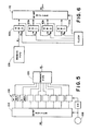
- n to m and m to n packing/unpacking means 102 unpacks the data from m bits to n bit format and packs the data from n to m bit format.
- the unpacking means includes an m-bit buffer 104 and n m/n:1 multiplexors 106, e.g. eight 4:1 multiplexors.
- a clock means 108 clocks the m/n:1 multiplexors m/n times as fast the m-bit buffer 104.
- the m-bit buffer 104 is clocked to bring in the next m-bit word to be broken down into m/n n-bit words.
- the next m/n clock cycles strobe the multiplexing means 106 continuing the process.
- the packing means includes m/n n-bit buffers, in the illustrated embodiment four 8-bit buffers 110a, 110b, 110c, 110d.
- the first 8-bits are loaded into the first 8-bit buffer 110a.
- the second clock pulse the first 8-bits are moved to the second buffer 110b and the next 8-bits are loaded into the first buffer 110a.
- tbe data is shifted one buffer such that three of them are filled.
- the first 8-bits are shifted to the fourth buffer 1106, the next 8-bits into the third 8-bit buffer 110c, the second 8-bits into the second 8-bit buffer 110b and the last 8-bits into the first 8-bit buffer 110a.
- all four 8-bit buffers are clocked simultaneously into a 32-bit buffer 112 forming the 32-bit long word. The number of buffers may be doubled to accommodate a 64-bit processor.
- the message When the message is received at the downstream node, it is converted from an optical signal to an electrical transmission by a converter means 120 and loaded into an elasticity buffer means 122.
- the elasticity buffer is clocked by timing signals interspersed among the message to load information into the elasticity buffer.
- the elasticity buffer is also clocked by ari internal clock 124 into a protocol defined communications layer 126. If the communications layer 126 recognizes its address in the message, it channels the information to a receive FIFO memory 128, through the packing means 102 and to the receive data management means 56 and the decoding means 58. Also, it clocks the message back to a transmitting means 130 which places the same message back on the network media 10.
- the clocks of the transmit and receive buffers transmit at the same frequency with an accuracy of four or five decimal places.
- clocks at the extremes of the tolerance range can build up a surplus or shortfall of several bytes in a 4 kilobyte transmission.
- the size of the packet is only limited by the size of the receive and transmit FIFO memories, larger packets may be transferred as larger FIFO memories become available.
- the elasticity buffer has no address ports, data is just strobed in as it is received at the transmitting node clock rate and strobed out as it is ready for retransfer or copying at the receive node clock rate.
- the node When the node seizes a token, it can generate packets on the ring. If the node needs to utilize the network for an extended duration, it issues a restricted token. other nodes having high priority small packets of data to transmit put out a priority flag. When a restricted token is passed around, the node with the priority flag can capture the restricted token and transmit a small packet of priority data. In this manner, associated equipment such as a laser imager which has a very small buffer, e.g. two lines, and must move its data around the network almost immediately to make room for the next lines, can keep control of the network while still allowing small data packets to be transferred in the time between lines.
- a laser imager which has a very small buffer, e.g. two lines, and must move its data around the network almost immediately to make room for the next lines, can keep control of the network while still allowing small data packets to be transferred in the time between lines.
- one of the nodes functions in a management capacity to verify the nodes in the network. It sends out a message with an address that is recognized by every node and instructions for each node to add its address to the end of the message.
- the transmitting node again receives the message, it contains a list of each node on the network in order.
- the managing node then formulates an ordered node list which is transmitted to all nodes.
- Each node continuously monitors the headers and trailing symbols of each message.
- the reception of frame indicators directs the nodes to monitor the fields which instruct each receiving node how to handle the message.
- the symbols can be indicative of the setting up of an ordered data node list, that information should be copied by all nodes, that the message may be stripped from the ring, whether the packet is valid, or the like.
- a ring error recovery is accomplished with a claim process.
- a node detects the absence of packet transmissions, it begins the claim process by generating a claim packet. Nodes receiving the claim packet with a source address less than their own pass on the received packets. A node that receives a claim packet with a source address greater than its own will remain in the claiming token state. A node that receives its own claim packet back will have won the arbitration and can generate a token. The failure of the node to receive a claim packet during the claim process indicates a serious ring fault. The node then enters a beacon process in which it generates a beacon packet that is receivable by all nodes. A node that receives its own beacon packet back having circumnavigated the ring, enters the claim process to begin initialization of the ring.
Abstract
Description
- The invention relates to high efficiency image data transfer networks and methods. It finds particular application in conjunction with the transfer of image data among electronic medical diagnostic equipments such as computed tomography (CT) scanners, magnetic resonance imagers, digital x-ray equipments, and other equipments that generate, process or display digital image information. However, it is to be appreciated that the invention will also find application in other areas, particularly where large blocks of data are to be transferred.
- Heretofore, medical diagnostic information has commonly been processed at each individual CT scanner, digital x-ray device, magnetic resonance imager or the like. Most often, the digital information is recorded on a removable disk or tape to facilitate carrying the image to other remote viewing locations. At the remote viewing locations, the radiologist could operate on the image data with various image enhancement algorithms and routines to enhance the diagnostic value for a particular application while the CT or other scanner was used to conduct further patient examinations. Rather than storing the image information on individual, portable disks, some hospitals have installed a central computer system with a large memory capacity for storing all digital images and other diagnostic data.
- Difficulty has arisen in transferring the image data among the scanners, the central archiving computer, distributed viewing terminals, and other stations. An image is typically about 4 megabytes of data. with improvements in the scanners and in the processing speed of the generated data, images will be made up of progressively larger blocks of digital data. Blocks of data of this magnitude are most easily transmitted on dedicated, direct transmission or communication lines, that is, on communication lines which interconnect each viewing terminal, for example, with each potential source of images. However, such direct dedicated lines are expensive and switching among them is inefficient. Moreover, conflict management, such as the conflict between several viewing terminals all requesting images from the same archive computer or CT scanner at the same time, is difficult to resolve.
- More commonlyl data is transferred among a plurality of stations or nodes on a common data bus. Various schemes have been developed for sharing the common bus, such as frequency or time division multiplexing. Most commonly, an asynchronous time division protocol is utilized.
- To prevent packets of transmitted data from colliding or interacting on the data bus, various polling policies have been established. Commonly, distributed polling policy is implemented, although central polling is also well known. Typical distributed or self polling schemes include token ring, logic ring, and the like.
- On the whole, the hardware and protocols associated with central bus and ring architecture have high associated overhead. This overhead reduces the efficiency of the system and increases data transfer times. Moreover, these distributed systems and protocols were designed for applications with relatively small data packets by the standards of image data transfers. The prior art systems were also designed for flexibility to handle a wide range of applications. This flexibility again increases the overhead with no productive advantage in image data transfer applications.
- Typically, at each data bus node, data is collected in the buffers of a file server from one or more sources. This data is recopied into a transport protocol hardware which adds its appropriate headers or other information. The data is copied from the buffers of the transport protocol to buffers of a queuing and multiplexing level, which again adds headers and other information to the data. The queuing and multiplexing level also oversees placing the data on the bus media in an efficient and fair way by the data link hardware. At the receive end, the data is again recopied from buffer to buffer as it is moved through the same layers, doubling the overhead.
- It is an object of the present invention to provide new and improved data transfer networks and methods which overcome the above referenced problems and others.
- According to a first aspect of the present invention there is provided a data transfer network comprising: a network media extending between each of a plurality of nodes; means for generating image representations connected with one of said nodes, each image representation including a relatively large block of image data; means for processing image data connected to another of said nodes; a first of said nodes including: buffer means for storing each of a plurality of image data packets, which taken together comprise an image data block, first data link means for transmitting each data packet on said network media, a second of the nodes including: second data link means for receiving the data packet from the network media; receiver memory means for storing at least one image data block, characterised in that: said first node includes a transmit data management means for controlling the transfer of data between said buffer means and said data link means and said second node includes receive data management means for transferring image data packets from said second data link means to said receiver memory means, and, receiver memory address control means for monitoring addresses of said receiver memory means at which previously received image data packets are stored and providing receiver memory addresses for each received image data packet.
- According to a second aspect of the present invention, there is provided a data transfer network comprising: a network media extending between each of a plurality of nodes; means for generating and processing large blocks of data connected with a plurality of said nodes; a first of said nodes including: data link means for receiving a plurality of data packets which taken together comprise one of the large blocks of data from the network media; and memory means for storing the large block of data; characterised in that said node further includes receive data management means for transferring each of the received data packets from said data link means to the memory means; and memory address control means for monitoring addresses of the memory means where previously received data packets are stored and for providing memory addresses for each subsequently received data packet.
- According to a third aspect of the present invention, there is provided a data transfer network comprising: a network media extending between a plurality of nodes; means for processing large blocks of data connected with at least some of the nodes; a first of the nodes transmitting data to a second of the nodes, characterised in that said second node includes: an elasticity buffer into which data from the first node is clocked at a clocking rate of the first node and out of which the data is clocked at a clocking rate of the second node, said elasticity buffer having a sufficient storage capacity to accommodate variable numbers of bits of data attributable to differences in the clocking rates of the first and second nodes.
- According to a fourth aspect of the present invention, there is provided a data transfer network comprising: a network media on which data is passed in n-bit format, where n is an integer, the network media extending between a plurality of nodes; means connected with said nodes for processing and handling blocks of m-bit format data, where m is an integer that is an even multiple of n; at least one of said nodes including: data link means for receiving n-bit data from said network media, m/n serially connected n-bit buffers, clocking means for clocking n-bit data from said data link means serially through the n-bit buffers until said buffers are filled and, when said buffers are filled concurrently clocking said buffers to pass an m-bit format word to the associated one of the data processing and handling means.
- According to a fifth aspect of the present invention, there is provided a data transfer network comprising: a network media extending between each of a plurality of nodes; means for processing and handling data connected with the nodes; characterised in that a first of the nodes includes: means for storing a plurality of data packets, each packet being designated for transmission to one of the other receiving nodes and being assigned a relative transmission priority, each designated receiving node having a statistical probability of availability to receive a transmitted data packet; data link means operatively connected with said storing means and said network media for transmitting data packets serially on said network media; data packet order determining means for determining an order in which said data link means transmits the stored data packets on said network media in accordance with a weighted combination of the assigned priority of each packet and the statistical availability probability of the corresponding designated receiving node.
- According to a sixth aspect of the present invention, there is provided a method of transferring data among a plurality of nodes interconnected by a network media, the method comprising: at a first of the nodes, storing at least one large block of image data, serially transmitting smaller data packets of the large data block on the network media to a second node and at a second node, serially receiving said data packets from the network media and storing each received packet in a memory; characterised in that said method includes the step of at said second node, keeping track of where packets corresponding to each data block being received packet by packet, are stored and directing each subsequently received packet to appropriate addresses in the memory.
- According to a seventh aspect of the present invention, there is provided a method of transferring data among a plurality of nodes which are interconnected by a plurality of nodes, the nodes being clocked at clocking rates which are close to each other but not exactly the same, characterised in that said method comprises the steps of: transmitting data from a first of the nodes at a first clocking rate; at a second of the nodes, clocking the data into a buffer at the first clocking rate and clocking the data out of the buffer at a second clocking rate at which the second node is clocked.
- According to an eighth aspect of the present invention, there is provided a method of transferring data between a plurality of devices that proces data in m-bit format on a network media that transmits data in an n-bit format, characterised in that the method comprises the steps of: clocking n-bit data serially through a plurality of n-bit buffers: when said n-blt buffers are filled, clocking said n-blt buffers concurrently to clock out an m-blt format word.
- According to a ninth aspect of the present invention, there is provided a method of transferring packets of data among a plurality of nodes that are interconnected by a network media, the method comprising the steps of: at one of the nodes, storing a plurality of packets of data, each of which is waiting for transmission on the media, to a designated one of said plurality of nodes, each packet having a designated priority and each designated node having a statistical probability of availability to receive a packet; and characterised in that said method comprises the step of serially transmitting the awaiting packets on the network media in an order established by a combination of both the relative priority of each packet and the statistical availability of the corresponding designated node.
- According to a tenth aspect of the present invention, there is provided a method of transferring large packets of data and small data transmissions among a plurality of nodes that are interconnected in a ring by a network media, characterised in that only a node which has a token is permitted to place a new data packet or a data transmission on the network media and characterised in that said method comprises the steps of: a first node, which has the token, intermittently transmitting new packets of data on the network media; between transmission of the data packets, said first node with the token passing a restricted token around the ring, said restricted token permitting a node possessing said restricted token to transmit smaller data transmissions over the network media but not the large data packets; as the restricted token is passed around the ring, a second node seizing the restricted token and transmitting a smaller data transmission to a third node.
- An advantage of the present invention is that it more efficiently transfers image data or other large packets of data.
- Another advantage of the present invention is that it is flexible and facilitates the adding of additional nodes to the network.
- One image data transfer network and method in accordance with the present invention will now be described by way of example with reference to the accompanying drawings in which:-
- Figure 1 is a system diagram of a data transfer network in accordance with the present invention;
- Figure 2 is a diagrammatic illustration of an exemplary transmit and receive node of the network of Figure 1;
- Figures 3A and 3B are a more detailed illustration of portions of the transmitting and receiving nodes of Figure 2;
- Figure 4 is a diagrammatic illustration of the data link assembly of Figures 2 and 3;
- Figure 5 is a diagrammatic illustration of the unpacking means of Figure 4; and
- Figure 6 is a schematic diagram of a packing scheme implemented by the packing means of Figure 4.
- Referring to Figure 1, an image data transfer network A interconnects a plurality of stations or nodes B. In the preferred embodiment, the data transfer network is composed of a plurality of lengths of fiber
optic cable 10 for transmitting data encoded light in a single direction from node to node. Of course, other transmission media may also be utilized as is known in the art. Each node retransmits the received information on the next length of fiber optic cable until the message has moved to each of the nodes and returned around the circle to the originating node. - Various nodes or stations may be provided. Typically, a plurality of scanners, such as a computed tomography (CT)
scanner 20, amagnetic resonance imager 22, and a laser, digital x-ray, nuclear camera, or otherdigital imager 24 may be used. The imagers at these nodes non-invasively examine a patient and generate image data indicative thereof. The imagers may process the image data at each station and transmit completed images or may convey the raw image data along the network to another node which is interconnected with an appropriately programmed computer for processing the data. An archiving computer memory means 26 stores a large plurality of images. Because images typically contain about 4 megabytes of data, the archiving memory means may typically have a plurality of hard disks. Other nodes of the network are connected withoperator control stations 28 from which the operator may control a scan, may view a selected image, operate on the selected image or images with various enhancement routines to improve their diagnostic value, and the like. The operator terminals may be interconnected with a hard copy apparatus for converting the electronically displayed diagnostic images into hard copy images on film, paper, or the like. other nodes of the system may be connected with a more simplephysician viewing station 30 at which a physician or radiologist may call up and view selected images for diagnostic purposes. - With reference to FIGURES 2 and 3A, each station node typically has both transmit and receive portions. When a request for an image or other data is made, a transmitting node portion associated with the request receiving station, e.g. one of the
CT scanners 20, sends packets of a reconstructed diagnostic image representations from itsimage memory 32 to the requesting node. When the reconstructed image representations are to be transferred by way of the network A, the image data is transferred through a data base means 34 to afile server 36. The file server typically receives and store an image in itstransmit buffers 38. Although the images are referenced herein as being 4 megabytes, it is to be appreciated that images may be much larger or smaller. - Smaller packets of the image data are transferred through a transport protocol means 40 without recopying to queuing
buffers 42 of a queuing and multiplexing means 44 under the control of a transmit data management means 46. The size of the packets is matched to the size of the queuing buffers. The queuing buffers are preferably as large as possible but are presently 4 kilobytes due to an unavailability of larger suitable buffer hardware. - The data in the queue buffers 42 may include high priority data in the priority buffer and lower priority data in a normal queue buffer. A transmit ordering means 48 controls the order in which the packets of data in queue buffers 42 are transferred.
- In the preferred embodiment, the transmit order is based on three factors: the relative priorities of the data, the statistical probability that the designated receive node will be available to receive the data, and the duration that the data has been waiting in the queuing buffer. More specifically, each of the data packets is assigned a value V:
V = aP + bA + cT (1),
where P is the relative priority of the data packets, A is the statistical availability of their designated receiving node, T is the duration or time that each of the data packets has been in the queuing memory, and a, b, and c are weighting factors. The weighting factors may be predetermined and assigned based on iterative adjustment, practical experience, or computer implemented system optimizing procedures. In the preferred embodiment, an adaptive control means 50 monitors the efficiency of the transmission of the data network and iteratively adjusts the weighting factors to improve and maintain the optimum efficiency with changing transmission patterns. - The data management means 46 adds appropriate header information to the data as it is moved from the file server buffers 38 to the queuing buffers 42. This header information includes a start delimiter, a destination node address, the source or transmitting node address, the 4 kilobyte data or packet field or information, an end delimiter, and a frame status.
- When the transmitting node is authorized to transmit information, a data link means 52 receives tbe packet data from the designated queue buffer and the header information from the data management means 46 to formulate a message. The message is applied to the
network media 10. Typically, the data message moves to the next node in the unidirectional data transmission direction where it is received and retransmitted. This receive and retransmit procedure continues until the receiving node recognizes its address in the header. - with continuing reference to FIGURE 2 and further reference to FIGURE 3B, a data link means 52′ at the receiving node retrieves the message and transmits it to a demultiplexing means 54. A receive data management means 56 receives the data packet and a decoding means 68 receives the multiplexing means applied headers. The header information is utilized to address a look-up table 60 which looks up the appropriate address for
buffers 62 of a file server 64. The headers are used to determine to which of a potential plurality of images each data packet corresponds. For a given designated image, the data packets are received in order. Thus, each received 4 kilobyte field or packet of data is loaded into the receiving buffer memory means 62 in the locations immediately following the preceding data packet of the same image. The buffer table means 60 keeps track of the appropriate starting address for each received packet or the ending address for the precedingly received packet. The received data management means 56 transfers the data packet to the receive buffer memory means 62 at the addresses designated by the buffer table means 60. In this manner, the data is transferred directly to the receive buffer memories of the file server 64 without the inefficiency of recopying by the demultiplexing means 54 or a transport protocol means 66. A data base meanS 70 transfers the 4 megabyte images to a processor or other portions of thesystem 72 at the receiving node. - Various techniques may be utilized for adjusting the weighting factors of
Equation 1. In a token ring protocol, the queries and the original messages return to the transmitting node with an indication whether they were accepted by the receiving node. A statistical table may be kept of the number of times the query or message comes back with an indication that each receiving node is busy. This information enables the transmit adaptive control means 50 to adjust the selection of packets from thebuffers 42 to pick the one which has the best prospects for being received. - A
multiplexing management system 74 receives information from a receivecontrol buffer 76 concerning which image or other data is requested. The multiplex management means 74 may be connected with the data link means 52 for placing image data requests on the network A to be communicated to the station that has the requested information. These image data requests are received by the data link 52 of the transmitting buffer and communicated to the appropriate file server and multiplexing meanscontrols multiplexor control 80 to provide the priority input regarding the order or transmission determination. - Various data management protocols may be utilized for managing the movement of data along the network A. In the preferred embodiment, a token ring type protocol is utilized in which messages are passed downstream from node to node around the ring. When a node detects its own address as the destination address, it copies the data packet into its buffers as described above. When the transmission returns to the transmitting node, the transmitting node strips the message from the ring and passes the token to the next node.
- In the normal mode of operation, the token is passed after each transmission to assure equal access to the network by all nodes. The token is a control signal that is used to grant a node the privilege to transmit on the ring. A node that wishes to transmit captures the token and removes it from the ring. The transmitting node first sends a query to determine whether the destination node can accept the information packet. A positive acknowledgement is generally returned by the addressed receiving node in the form of trailing indicators that have been modified by the destination to designate its status. The transmitting node now formulates a message including headers as described above and a data packet - in the preferred embodiment, 4 kilobytes. The message is passed from node to node and copied by the destination node if it is available to receive. The destination node modifies the header information or trailing indicators to indicate whether or not it copied the information. When the message is returned to the transmitting node, it removes it from the network and notes whether or not the receiving node copied the information. If the information was copied, the transmitting node readies its next packet of information; if the information was not copied, the transmitting mode prepares to retransmit the packet again. In either instance, the token is passed.
- The protocol for controlling each node can be described as two separate state machines that communicate with each other - the receiver state and the transmitter state. Symbols within each packet arrive at the receiver asynchronously to the state of the transmitter. This requires that the receiver receive packets concurrently with other actions which may be being undertaken by the transmitter. The transmitter is informed of various receiver events, such as the reception of a claim packet. Notification occurs through signals that are passed from one state machine to the other. Global signals are used for events that cause responses from both machines. The receiver continuously monitors the signal stream that is being received and detects valid frames and tokens. packets whose destination address matches the nodes own address are copied if the buffer space is available and the appropriate process is notified. The transmitter is informed of tokens and frames that are received.
- The receiver machine enters a listen state when it is initialized. This happens on power up or if a violation has occurred. Violations include a loss of synchronization with an upstream node. Receipt of a valid synchronization symbol indicates that synchronization has been reachieved. The receiver further scans the input symbol stream for commands that indicate the start of either the token or frame packets. The receiver also monitors for receipt of the token, the start of a frame, and the like. If data addressed to the receiver is copied into the buffers, an appropriate flag is set. This flag acknowledges the receipt to the transmitting node.
- With reference to FIGURE 4, when the query comes back to the transmit node that the destination node is available to receive, it moves the data packet into a first in/first out (FIFO) transmit
memory 100 of thedata link 52. The data packets are set up for m-bit processors; whereas, the networks transfer n-bit data. Typically, m = 32 and n = 8. However, these values are based on hardware availability and are not constraints on the present invention. An n to m and m to n packing/unpacking means 102 unpacks the data from m bits to n bit format and packs the data from n to m bit format. - With reference to FIGURE 5, the unpacking means includes an m-
bit buffer 104 and n m/n:1multiplexors 106, e.g. eight 4:1 multiplexors. A clock means 108 clocks the m/n:1 multiplexors m/n times as fast the m-bit buffer 104. There are n one bit lines extending in parallel from the multiplexors to the transmitmemory 100 to move n-bit packets of data into the transmitFIFO memory 100. After the multiplexors have been clocked m/n times, the m-bit buffer 104 is clocked to bring in the next m-bit word to be broken down into m/n n-bit words. The next m/n clock cycles strobe the multiplexing means 106 continuing the process. - With reference to FIGURE 6, when data is received, it is received in n-bit data segments and packed by the packing means into m-bit words. The packing means includes m/n n-bit buffers, in the illustrated embodiment four 8-
bit buffers bit buffer 110a. On the second clock pulse, the first 8-bits are moved to the second buffer 110b and the next 8-bits are loaded into thefirst buffer 110a. Similarly, on the third clock pulse, tbe data is shifted one buffer such that three of them are filled. On the fourth clock pulse, the first 8-bits are shifted to the fourth buffer 1106, the next 8-bits into the third 8-bit buffer 110c, the second 8-bits into the second 8-bit buffer 110b and the last 8-bits into the first 8-bit buffer 110a. On the fifth clock pulse, all four 8-bit buffers are clocked simultaneously into a 32-bit buffer 112 forming the 32-bit long word. The number of buffers may be doubled to accommodate a 64-bit processor. - When the message is received at the downstream node, it is converted from an optical signal to an electrical transmission by a converter means 120 and loaded into an elasticity buffer means 122. The elasticity buffer is clocked by timing signals interspersed among the message to load information into the elasticity buffer. The elasticity buffer is also clocked by ari
internal clock 124 into a protocol definedcommunications layer 126. If thecommunications layer 126 recognizes its address in the message, it channels the information to a receiveFIFO memory 128, through the packing means 102 and to the receive data management means 56 and the decoding means 58. Also, it clocks the message back to a transmitting means 130 which places the same message back on thenetwork media 10. - It is to be appreciated that the clocks of the transmit and receive buffers transmit at the same frequency with an accuracy of four or five decimal places. However, clocks at the extremes of the tolerance range can build up a surplus or shortfall of several bytes in a 4 kilobyte transmission. Because the size of the packet is only limited by the size of the receive and transmit FIFO memories, larger packets may be transferred as larger FIFO memories become available. Accordingly, it is advantageous to size the elasticity buffer with sufficient capacity to assure that even with larger FIFO buffers and even when plural messages follow back to back or other extreme conditions occur, the elasticity buffer can accommodate a sufficient number of bytes to handle the full deviation in clock speed tolerances, for example, about 5 bytes. It is to be appreciated that the elasticity buffer has no address ports, data is just strobed in as it is received at the transmitting node clock rate and strobed out as it is ready for retransfer or copying at the receive node clock rate.
- When the node seizes a token, it can generate packets on the ring. If the node needs to utilize the network for an extended duration, it issues a restricted token. other nodes having high priority small packets of data to transmit put out a priority flag. When a restricted token is passed around, the node with the priority flag can capture the restricted token and transmit a small packet of priority data. In this manner, associated equipment such as a laser imager which has a very small buffer, e.g. two lines, and must move its data around the network almost immediately to make room for the next lines, can keep control of the network while still allowing small data packets to be transferred in the time between lines.
- Periodically, one of the nodes functions in a management capacity to verify the nodes in the network. It sends out a message with an address that is recognized by every node and instructions for each node to add its address to the end of the message. When the transmitting node again receives the message, it contains a list of each node on the network in order. The managing node then formulates an ordered node list which is transmitted to all nodes.
- Each node continuously monitors the headers and trailing symbols of each message. The reception of frame indicators directs the nodes to monitor the fields which instruct each receiving node how to handle the message. The symbols can be indicative of the setting up of an ordered data node list, that information should be copied by all nodes, that the message may be stripped from the ring, whether the packet is valid, or the like.
- A ring error recovery is accomplished with a claim process. When a node detects the absence of packet transmissions, it begins the claim process by generating a claim packet. Nodes receiving the claim packet with a source address less than their own pass on the received packets. A node that receives a claim packet with a source address greater than its own will remain in the claiming token state. A node that receives its own claim packet back will have won the arbitration and can generate a token. The failure of the node to receive a claim packet during the claim process indicates a serious ring fault. The node then enters a beacon process in which it generates a beacon packet that is receivable by all nodes. A node that receives its own beacon packet back having circumnavigated the ring, enters the claim process to begin initialization of the ring.
Claims (25)
Applications Claiming Priority (2)
| Application Number | Priority Date | Filing Date | Title |
|---|---|---|---|
| US07/439,859 US4993025A (en) | 1989-11-21 | 1989-11-21 | High efficiency image data transfer network |
| US439859 | 1989-11-21 |
Publications (2)
| Publication Number | Publication Date |
|---|---|
| EP0429201A2 true EP0429201A2 (en) | 1991-05-29 |
| EP0429201A3 EP0429201A3 (en) | 1993-04-21 |
Family
ID=23746423
Family Applications (1)
| Application Number | Title | Priority Date | Filing Date |
|---|---|---|---|
| EP19900311927 Withdrawn EP0429201A3 (en) | 1989-11-21 | 1990-10-31 | High efficiency image data transfer networks and methods |
Country Status (3)
| Country | Link |
|---|---|
| US (1) | US4993025A (en) |
| EP (1) | EP0429201A3 (en) |
| JP (1) | JPH03185948A (en) |
Cited By (5)
| Publication number | Priority date | Publication date | Assignee | Title |
|---|---|---|---|---|
| EP0686927A1 (en) * | 1994-06-10 | 1995-12-13 | Agfa-Gevaert N.V. | System for supplying a processed radiographic image to a remote device |
| US6954802B2 (en) | 1998-09-29 | 2005-10-11 | Tdk Electronics Corporation | Removable media recording station for the medical industry |
| US20120230338A1 (en) * | 2011-03-09 | 2012-09-13 | Annai Systems, Inc. | Biological data networks and methods therefor |
| US9177101B2 (en) | 2010-08-31 | 2015-11-03 | Annai Systems Inc. | Method and systems for processing polymeric sequence data and related information |
| US9350802B2 (en) | 2012-06-22 | 2016-05-24 | Annia Systems Inc. | System and method for secure, high-speed transfer of very large files |
Families Citing this family (52)
| Publication number | Priority date | Publication date | Assignee | Title |
|---|---|---|---|---|
| US5333267A (en) * | 1990-05-29 | 1994-07-26 | Apple Computer, Inc. | Ring interconnect system architecture |
| US5261059A (en) * | 1990-06-29 | 1993-11-09 | Digital Equipment Corporation | Crossbar interface for data communication network |
| US5121383A (en) * | 1990-11-16 | 1992-06-09 | Bell Communications Research, Inc. | Duration limited statistical multiplexing in packet networks |
| US5200993A (en) * | 1991-05-10 | 1993-04-06 | Bell Atlantic Network Services, Inc. | Public telephone network including a distributed imaging system |
| JP3051533B2 (en) * | 1991-12-26 | 2000-06-12 | マツダ株式会社 | Multiplex transmission method and multiple transmission device |
| US5826198A (en) * | 1992-01-13 | 1998-10-20 | Microcom Systems, Inc. | Transmission of data over a radio frequency channel |
| US5276681A (en) * | 1992-06-25 | 1994-01-04 | Starlight Networks | Process for fair and prioritized access to limited output buffers in a multi-port switch |
| MX9306994A (en) * | 1992-12-15 | 1994-06-30 | Ericsson Telefon Ab L M | FLOW CONTROL SYSTEM FOR PACKAGE SWITCHES. |
| US5381413A (en) * | 1992-12-28 | 1995-01-10 | Starlight Networks | Data throttling system for a communications network |
| JP3360905B2 (en) * | 1993-01-04 | 2003-01-07 | ゼロックス・コーポレーション | Printing system |
| JPH06277207A (en) * | 1993-03-25 | 1994-10-04 | Toshiba Corp | Non-destructive inspection device, x-ray ct data detecting device and x-ray ct image processor |
| US5420853A (en) * | 1993-04-05 | 1995-05-30 | Motorola, Inc. | Self controlling crossbar switch and method |
| US5530902A (en) * | 1993-06-14 | 1996-06-25 | Motorola, Inc. | Data packet switching system having DMA controller, service arbiter, buffer type managers, and buffer managers for managing data transfer to provide less processor intervention |
| CA2130395C (en) * | 1993-12-09 | 1999-01-19 | David G. Greenwood | Multimedia distribution over wide area networks |
| JP2596718B2 (en) | 1993-12-21 | 1997-04-02 | インターナショナル・ビジネス・マシーンズ・コーポレイション | How to manage network communication buffers |
| JPH07288593A (en) * | 1994-04-15 | 1995-10-31 | Canon Inc | Information processing system, information processing device and data transfer control method |
| JPH086796A (en) * | 1994-06-15 | 1996-01-12 | Nec Corp | Down-loading method, network system therefor and data file updating method |
| US6091507A (en) | 1994-07-01 | 2000-07-18 | Colorspan Corporation | Method and apparatus for printing a document over a network |
| US5786994A (en) * | 1994-11-23 | 1998-07-28 | Imation Corp. | Performance monitoring system and method for a laser medical imager |
| US6282203B1 (en) * | 1995-06-28 | 2001-08-28 | Hyundai Electronics Ind. Co., Ltd. | Packet data transmitting apparatus, and method therefor |
| JP3288213B2 (en) | 1996-01-11 | 2002-06-04 | 日本電気株式会社 | server |
| KR100217738B1 (en) * | 1996-03-12 | 1999-09-01 | 구자홍 | Computer communication speed improving method of keyphone |
| US6038604A (en) * | 1997-08-26 | 2000-03-14 | International Business Machines Corporation | Method and apparatus for efficient communications using active messages |
| US6377562B1 (en) | 1997-11-18 | 2002-04-23 | Bell Atlantic Network Services, Inc. | Wireless asymmetric local loop (WASL) communication |
| US6240094B1 (en) | 1997-12-22 | 2001-05-29 | Bell Atlantic Network Services, Inc. | Statistical time division multiplexer for a wireless asymmetric local loop communication system |
| US6230043B1 (en) * | 1998-09-30 | 2001-05-08 | General Electric Company | Method and apparatus for capturing and automatically transferring an x-ray image to a remote location |
| US6272469B1 (en) * | 1998-11-25 | 2001-08-07 | Ge Medical Systems Global Technology Company, Llc | Imaging system protocol handling method and apparatus |
| US6678703B2 (en) | 2000-06-22 | 2004-01-13 | Radvault, Inc. | Medical image management system and method |
| US20020016718A1 (en) * | 2000-06-22 | 2002-02-07 | Rothschild Peter A. | Medical image management system and method |
| US20030061318A1 (en) * | 2001-09-27 | 2003-03-27 | International Business Machines Corporation | Apparatus and method of ascertaining remote systems accessibility before running remote commands |
| US7660886B2 (en) * | 2001-09-27 | 2010-02-09 | International Business Machines Corporation | Apparatus and method of representing real-time distributed command execution status across distributed systems |
| US7051039B1 (en) | 2001-09-28 | 2006-05-23 | Oracle International Corporation | Mechanism for uniform access control in a database system |
| US7020653B2 (en) * | 2002-11-06 | 2006-03-28 | Oracle International Corporation | Techniques for supporting application-specific access controls with a separate server |
| US8694510B2 (en) * | 2003-09-04 | 2014-04-08 | Oracle International Corporation | Indexing XML documents efficiently |
| US8229932B2 (en) | 2003-09-04 | 2012-07-24 | Oracle International Corporation | Storing XML documents efficiently in an RDBMS |
| US20050182639A1 (en) * | 2004-02-18 | 2005-08-18 | Fujitsu Limited | Dynamic virtual organization manager |
| US7623543B2 (en) * | 2004-03-19 | 2009-11-24 | Fujitsu Limited | Token-controlled data transmissions in communication networks |
| US7529267B2 (en) * | 2004-03-19 | 2009-05-05 | Fujitsu Limited | Data transmissions in communication networks using multiple tokens |
| US7965732B2 (en) * | 2004-03-19 | 2011-06-21 | Fujitsu Limited | Scheduling token-controlled data transmissions in communication networks |
| US7930277B2 (en) * | 2004-04-21 | 2011-04-19 | Oracle International Corporation | Cost-based optimizer for an XML data repository within a database |
| US20070208946A1 (en) * | 2004-07-06 | 2007-09-06 | Oracle International Corporation | High performance secure caching in the mid-tier |
| US8073841B2 (en) * | 2005-10-07 | 2011-12-06 | Oracle International Corporation | Optimizing correlated XML extracts |
| US8949455B2 (en) | 2005-11-21 | 2015-02-03 | Oracle International Corporation | Path-caching mechanism to improve performance of path-related operations in a repository |
| US7797310B2 (en) * | 2006-10-16 | 2010-09-14 | Oracle International Corporation | Technique to estimate the cost of streaming evaluation of XPaths |
| US20080124081A1 (en) * | 2006-11-27 | 2008-05-29 | Takeo Hamada | Predictive scheduling of data path control |
| US8634430B2 (en) * | 2006-11-27 | 2014-01-21 | Fujitsu Limited | Multicast transmissions in optical burst transport |
| US7826747B2 (en) * | 2006-11-27 | 2010-11-02 | Fujitsu Limited | Optical burst transport using an electro-optic switch |
| US8111767B2 (en) * | 2007-05-31 | 2012-02-07 | Renesas Electronics Corporation | Adaptive sliding block Viterbi decoder |
| US7958112B2 (en) * | 2008-08-08 | 2011-06-07 | Oracle International Corporation | Interleaving query transformations for XML indexes |
| US10560357B2 (en) | 2017-11-28 | 2020-02-11 | Marvell World Trade Ltd. | Distributed checksum calculation for communication packets |
| US10469633B2 (en) * | 2018-03-29 | 2019-11-05 | Marvell World Trade Ltd. | Low-latency pipeline for media-to-ethernet frame packaging |
| US10673994B2 (en) | 2018-03-29 | 2020-06-02 | Marvell International Ltd. | Network packet generator employing multiple header templates and configurable hardware registers |
Citations (3)
| Publication number | Priority date | Publication date | Assignee | Title |
|---|---|---|---|---|
| US4489379A (en) * | 1982-01-25 | 1984-12-18 | International Business Machines Corporation | Distributed data processing in ring-structured networks architected for full duplex peer-to-peer operation of processing stations and uninterruptible transfer of long data records between stations |
| GB2162406A (en) * | 1984-06-18 | 1986-01-29 | Logica Uk Ltd | Computer system |
| US4653112A (en) * | 1985-02-05 | 1987-03-24 | University Of Connecticut | Image data management system |
Family Cites Families (3)
| Publication number | Priority date | Publication date | Assignee | Title |
|---|---|---|---|---|
| US4785449A (en) * | 1984-05-21 | 1988-11-15 | Canon Kabushiki Kaisha | Network system for data transmission among plural communications stations connected to a communication medium |
| NL8500841A (en) * | 1985-03-22 | 1986-10-16 | Philips Nv | ENCRYPTION OR DECODING CIRCUIT FOR TIME MULTIPLEX AND SIMULTANEOUS SIGNALS. |
| US4780870A (en) * | 1986-09-05 | 1988-10-25 | American Telephone And Telegraph Company, At&T Bell Laboratories | Packet switch |
-
1989
- 1989-11-21 US US07/439,859 patent/US4993025A/en not_active Expired - Lifetime
-
1990
- 1990-10-31 EP EP19900311927 patent/EP0429201A3/en not_active Withdrawn
- 1990-11-15 JP JP2307341A patent/JPH03185948A/en active Pending
Patent Citations (3)
| Publication number | Priority date | Publication date | Assignee | Title |
|---|---|---|---|---|
| US4489379A (en) * | 1982-01-25 | 1984-12-18 | International Business Machines Corporation | Distributed data processing in ring-structured networks architected for full duplex peer-to-peer operation of processing stations and uninterruptible transfer of long data records between stations |
| GB2162406A (en) * | 1984-06-18 | 1986-01-29 | Logica Uk Ltd | Computer system |
| US4653112A (en) * | 1985-02-05 | 1987-03-24 | University Of Connecticut | Image data management system |
Non-Patent Citations (1)
| Title |
|---|
| REVIEW OF THE ELECTRICAL COMMUNICATION LABORATORIES vol. 34, no. 5, September 1986, TOKYO JP pages 577 - 585 E. VOZUMI 'Processor to processor communication interface unit' * |
Cited By (13)
| Publication number | Priority date | Publication date | Assignee | Title |
|---|---|---|---|---|
| EP0686927A1 (en) * | 1994-06-10 | 1995-12-13 | Agfa-Gevaert N.V. | System for supplying a processed radiographic image to a remote device |
| US6954802B2 (en) | 1998-09-29 | 2005-10-11 | Tdk Electronics Corporation | Removable media recording station for the medical industry |
| US9189594B2 (en) | 2010-08-31 | 2015-11-17 | Annai Systems Inc. | Method and systems for processing polymeric sequence data and related information |
| US9177101B2 (en) | 2010-08-31 | 2015-11-03 | Annai Systems Inc. | Method and systems for processing polymeric sequence data and related information |
| US9177100B2 (en) | 2010-08-31 | 2015-11-03 | Annai Systems Inc. | Method and systems for processing polymeric sequence data and related information |
| US9177099B2 (en) | 2010-08-31 | 2015-11-03 | Annai Systems Inc. | Method and systems for processing polymeric sequence data and related information |
| US20120233201A1 (en) * | 2011-03-09 | 2012-09-13 | Annai Systems, Inc. | Biological data networks and methods therefor |
| US20120232874A1 (en) * | 2011-03-09 | 2012-09-13 | Annai Systems, Inc. | Biological data networks and methods therefor |
| US8982879B2 (en) | 2011-03-09 | 2015-03-17 | Annai Systems Inc. | Biological data networks and methods therefor |
| US20120230338A1 (en) * | 2011-03-09 | 2012-09-13 | Annai Systems, Inc. | Biological data networks and methods therefor |
| US9215162B2 (en) | 2011-03-09 | 2015-12-15 | Annai Systems Inc. | Biological data networks and methods therefor |
| US9350802B2 (en) | 2012-06-22 | 2016-05-24 | Annia Systems Inc. | System and method for secure, high-speed transfer of very large files |
| US9491236B2 (en) | 2012-06-22 | 2016-11-08 | Annai Systems Inc. | System and method for secure, high-speed transfer of very large files |
Also Published As
| Publication number | Publication date |
|---|---|
| JPH03185948A (en) | 1991-08-13 |
| EP0429201A3 (en) | 1993-04-21 |
| US4993025A (en) | 1991-02-12 |
Similar Documents
| Publication | Publication Date | Title |
|---|---|---|
| US4993025A (en) | High efficiency image data transfer network | |
| US4866704A (en) | Fiber optic voice/data network | |
| JP3168235B2 (en) | High-speed packet switching apparatus and data packet routing method | |
| US5615211A (en) | Time division multiplexed backplane with packet mode capability | |
| US5604742A (en) | Communications system and method for efficient management of bandwidth in a FDDI station | |
| US4500989A (en) | Digital communication system | |
| EP0772323A2 (en) | Method and apparatus for tracking buffer availability | |
| US20090089303A1 (en) | Method and apparatus for transmission and storage of digital medical data | |
| EP0752801A2 (en) | Method and apparatus for controlling data flow through an ATM interface | |
| US20040177197A1 (en) | Method and apparatus for extending the range of the universal serial bus protocol | |
| WO2000060819A9 (en) | Process for automatic detection of and quality of service adjustment for bulk data transfers | |
| WO2000019672A1 (en) | Method and system for communicating information in a network | |
| US4638477A (en) | Packet exchange data transmission system | |
| EP0534882A2 (en) | Multi-channel communications system | |
| JPS63500764A (en) | Packet-switched local circuitry with prioritized random partitioning and conflict detection | |
| JP2559940B2 (en) | Buffer service method and apparatus | |
| EP0276468B1 (en) | Data transmission control method | |
| Martinez et al. | Design and performance evaluation of a high speed fiber optic integrated computer network for picture archiving and communications system | |
| Honeyman et al. | Teleradiology and network strategies | |
| Franta et al. | HYPERchannel local network interconnection through satellite links | |
| Honeyman | Teleradiology and Network Strategies Janice C. Honeyman 1 and Samuel J. Dwyer, III 2 1 Department of Radiology, University of Florida Medical Center, Gainesville, Fl 32610 2 Department of Radiology, University of Kansas Medical Center, Kansas City, KS, 66103 | |
| Vossebuerger et al. | ImNet, a fiber optic network with multistar topology for high-speed data transmission | |
| Nemat et al. | A high speed integrated computer network for picture archiving and communication system (PACS) | |
| Persons et al. | Performance characteristics of the Mayo/IBM PACS | |
| EP0766429A2 (en) | Method and apparatus for buffer management |
Legal Events
| Date | Code | Title | Description |
|---|---|---|---|
| PUAI | Public reference made under article 153(3) epc to a published international application that has entered the european phase |
Free format text: ORIGINAL CODE: 0009012 |
|
| AK | Designated contracting states |
Kind code of ref document: A2 Designated state(s): DE FR NL |
|
| PUAL | Search report despatched |
Free format text: ORIGINAL CODE: 0009013 |
|
| AK | Designated contracting states |
Kind code of ref document: A3 Designated state(s): DE FR NL |
|
| 17P | Request for examination filed |
Effective date: 19931018 |
|
| 17Q | First examination report despatched |
Effective date: 19940909 |
|
| STAA | Information on the status of an ep patent application or granted ep patent |
Free format text: STATUS: THE APPLICATION IS DEEMED TO BE WITHDRAWN |
|
| 18D | Application deemed to be withdrawn |
Effective date: 19950314 |