EP0420030A2 - Bar code as well as procedure and device for reading such a code - Google Patents
Bar code as well as procedure and device for reading such a code Download PDFInfo
- Publication number
- EP0420030A2 EP0420030A2 EP90118067A EP90118067A EP0420030A2 EP 0420030 A2 EP0420030 A2 EP 0420030A2 EP 90118067 A EP90118067 A EP 90118067A EP 90118067 A EP90118067 A EP 90118067A EP 0420030 A2 EP0420030 A2 EP 0420030A2
- Authority
- EP
- European Patent Office
- Prior art keywords
- sensor
- code
- strips
- coil
- strip
- Prior art date
- Legal status (The legal status is an assumption and is not a legal conclusion. Google has not performed a legal analysis and makes no representation as to the accuracy of the status listed.)
- Granted
Links
Images


Classifications
-
- G—PHYSICS
- G06—COMPUTING; CALCULATING OR COUNTING
- G06K—GRAPHICAL DATA READING; PRESENTATION OF DATA; RECORD CARRIERS; HANDLING RECORD CARRIERS
- G06K19/00—Record carriers for use with machines and with at least a part designed to carry digital markings
- G06K19/06—Record carriers for use with machines and with at least a part designed to carry digital markings characterised by the kind of the digital marking, e.g. shape, nature, code
- G06K19/06187—Record carriers for use with machines and with at least a part designed to carry digital markings characterised by the kind of the digital marking, e.g. shape, nature, code with magnetically detectable marking
-
- G—PHYSICS
- G06—COMPUTING; CALCULATING OR COUNTING
- G06K—GRAPHICAL DATA READING; PRESENTATION OF DATA; RECORD CARRIERS; HANDLING RECORD CARRIERS
- G06K7/00—Methods or arrangements for sensing record carriers, e.g. for reading patterns
- G06K7/08—Methods or arrangements for sensing record carriers, e.g. for reading patterns by means detecting the change of an electrostatic or magnetic field, e.g. by detecting change of capacitance between electrodes
- G06K7/082—Methods or arrangements for sensing record carriers, e.g. for reading patterns by means detecting the change of an electrostatic or magnetic field, e.g. by detecting change of capacitance between electrodes using inductive or magnetic sensors
- G06K7/087—Methods or arrangements for sensing record carriers, e.g. for reading patterns by means detecting the change of an electrostatic or magnetic field, e.g. by detecting change of capacitance between electrodes using inductive or magnetic sensors flux-sensitive, e.g. magnetic, detectors
Definitions
- the invention relates to a method for reading strip or bar codes, the strip code being placed under a reading head and the code being read by means of the reading head, and a device for reading a strip or bar code with changing electromagnetic properties and a strip code.
- Optical stripe or bar codes are known. They consist of a number of narrow and wide lines and gaps, which are arranged in parallel next to each other. As a rule, the coding of information in such strips and gaps is based on the binary principle.
- the invention has for its object to provide new strip code materials and to create a new method and a new device for reading such, which also under Conditions can be used in which optical bar codes cannot be used.
- the stated object is achieved by a method of the type mentioned at the outset, which is characterized in that an electromagnetic alternating field is generated via a strip code formed by strips and gaps between them with different electromagnetic properties, and a measuring field which can be changed by the strip code is detected.
- a device for reading a bar code of changing electromagnetic properties is characterized by at least one sensor with a sensor core, an excitation coil that is acted on it with a high frequency, and in each case at least one sensor coil that is closely adjacent to the excitation coil.
- a strip code according to the invention provides strips of electrically conductive material arranged on a carrier with spaces.
- a method and system for the inductive recognition of bar codes is thus created, which consist of an electrically conductive, preferably metallic material.
- the gaps or spaces between the strips of electrically conductive material are retained as gaps in the preferably non-conductive dielectric carrier material or can be poured out by means of such material, which is also used as a cover layer.
- the cover layer does not have to be made of transparent material, but can be opaque.
- the strips consist of para- or diamagnetic, conductive material, preferably copper or other highly conductive material, eddy currents which weaken the magnetic field are generated in this material when an alternating field is introduced via the sensor head.
- conductive material preferably copper or other highly conductive material
- ferromagnetic carrier and covering material can also be provided, for example stainless steel, in particular in corrosive environments; if necessary, the actual carrier and the covering material must be separated from the strips by insulating layers.
- the strips can also basically consist of ferromagnetic material.
- the carrier and cover material is also preferably made of dielectric material such as plastic or the like; in principle, however, non-ferromagnetic, that is to say para- or diamagnetic, carrier and covering material can also be used.
- a preferred embodiment provides that a reference field is measured by means of a reference coil to compensate for the measuring coil current.
- the reference field is usually a field area that is practically not influenced by the code strips and is measured accordingly with a reference coil, which is further from the code strips than the measuring coil, so that the signal emitted by it is not influenced.
- the reference coil is used (in the absence of the strips to be measured) to compensate for the measuring field or for zero adjustment.
- the compensation or the adjustment can also be done in combination with electrical measures or purely electronically; in the former case, different amplifiers can be arranged in one of the two branches or amplification factors can act; phase shifters can be provided.
- the reference and measurement signals are fed to a differential amplifier whose output signal (in the absence of bar codes) is tuned to zero.
- the further electronic elements of the processing device provide that devices for filtering out disturbing DC and harmonic components (bandpass), a synchronous demodulator or a sample-hold circuit for rectifying the differential voltages and a low-pass filter or an equivalent means for filtering out the carrier frequency are provided are.
- the rectified, pure emergency signal obtained is preferably used by means of a peak value detection, as is known from DE-OS 36 01 083 and to which express reference is made and whose disclosure content is made the subject of the present disclosure.
- the resulting TTL signal which exactly represents the bar code, can then be analyzed in a suitable manner and the information contained in the bar code can accordingly be recovered.
- the code stripe structure for example with effective Cu stripes, can be produced by placing corresponding stripes on a carrier.
- an entire coherent bar code can be cut out of a corresponding wall material in one process.
- the corresponding structure can be sprayed onto a carrier in the metal spraying process, the areas to be left exposed being covered by a mask the.
- cold-welded Cu structures in the base material can be produced by pressing and explosive forming.
- the effective (Cu) structure can be used without a cover. It can be enclosed by a plastic. Furthermore, it can be covered with V2A sheet metal. A carrier can also be V2A sheet, so that the effective (Cu) structure can be introduced between two V2A sheets. Finally, the Cu structure can be overmolded or overmolded using V2A using a metal spraying process.
- the application or connection of the active structure can be non-positive, e.g. by clamping. It can be carried out in a form-fitting manner by inserting the strips into corresponding grooves in a carrier, e.g. Steel.
- a carrier e.g. Steel.
- Other detachable or non-detachable holders such as by means of a screwed or riveted cover, can also be used.
- the cover can be glued to the carrier.
- the materials can be connected with or without filler material, for example by soldering, welding, such as, in particular, plasma welding, by roller seam, laser or electron beam.
- While a single bar code can be applied to form a code card on a carrier, in order to increase the information content of a code card, it can be provided with a plurality of code tracks arranged next to one another, each taking up a corresponding part of the height of the carrier, the total number being the maximum possible width or height of the carrier and the minimum permissible width of the code track or height of the individual strips thereof is determined.
- the code tracks arranged side by side can be read out one after the other (serial). All or part of the traces of a code card can also be stored in parallel several sensors, in particular also read in using the multiplex method, and then further processed electronically.
- the code carrier can be circularly symmetrical, the individual strips being formed by circular sectors.
- the sensors are also preferably adapted to the code card structure and are therefore designed as circular sectors.
- the circular code cards can be held and centered centrally, for example by means of a central punch. The sensors are guided over a circular path.
- the strips 3, 4 consist of conductive material, either of highly conductive di- or paramagnetic material, such as copper or the like, or of ferromagnetic material.
- the carrier 1 and the cover 8 are usually made of non-conductive, ie dielectric material, such as plastic in particular, which does not have to be transparent.
- strips 3, 4 made of ferromagnetic material can have a carrier and cover made of materials other than dielectric, para- and dlamagnetic, for example copper.
- stainless steel can also be used as the material for the carrier 1 and the cover 8.
- a card made of a support plate 1.8 made of stainless steel, strips or code bars 3.4 made of copper and between these stainless steel strips (not shown) inserted in between spaces can exist as "code gaps", copper being held in stainless steel strips by a steel frame (not shown) .
- code gaps copper being held in stainless steel strips by a steel frame (not shown) .
- Such an arrangement can be firmly connected by welding or crimping, so that such a card meets the highest mechanical, chemical and thermal requirements.
- the resolution or reading accuracy is determined by the geometric sizes.
- the layer thickness of the code lines is preferably selected in the range from 20 to 100 micrometers.
- the width of the strips 3, 4 and the spaces 6, 7 is preferably in the range from 0.5 to 1 mm, but can also be up to 4 mm or more.
- the carrier material can largely be of any thickness, the cover 8 on the side on which the sensor head is placed should be in the range from 0.1 to 2 mm; in the case of a card-like strip arrangement, the carrier material in this strength will also be chosen.
- the length of the strips 3, 4 is largely uncritical; practically it is chosen in the range of 1 to 4 cm.
- the bar code can be produced in any suitable manner.
- the strips can be punched out or cut out of the appropriate material and then melted into plastic, for example. Etching, as is customary in the production of printed circuit boards, can be used for the production. Furthermore, other suitable thick or thin layer processes or also adhesive processes can be used depending on the materials used.
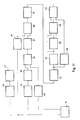
- FIG. 2 shows a basic illustration of a sensor 11 according to the invention.
- the sensor 11 has a sensor core 12 made of ferromagnetic material.
- the sensor core 12 carries 3 coils 13, 14, 16.
- the core 12 is H-shaped.
- the H-core sensor can be "sharpened” on one (or on both) end face (s) by fitting it with a (saddle) roof and a corresponding one (Saddle) edge 15 is provided, as shown in Fig.2.
- the coil 13 is wound as an excitation coil on the H-bridge.
- a high-frequency AC voltage is applied to the excitation coil 13.
- two separate magnetic circuits are built up, which are each closed over the end faces of adjacent legs of the H-core 12.
- One of the coils 14, 16 is wound on each of the two adjacent legs of the H-core, one of the coils (here 14) being the measuring coil, while the coil 16 is a reference coil.
- a voltage is in turn induced in the coils 14, 16 by the magnetic alternating field generated in the coil 13 via the high-frequency alternating voltage. which is adjusted to zero when the coils 14, 16 are connected to one another.
- One improvement is to carry out the rough adjustment via the number of turns and the coil position and to carry out a fine adjustment by adding up a correction signal that can be adjusted in amplitude and phase position.
- FIG. 3 shows an H-core 12a which basically has the shape of an upside-down A's, but the side legs of the A's do not touch each other in the region of the tapering tip, but form a gap 17.
- the legs 18, 19 are also approximately semicircular in cross-section, so that the tip region at 21 results in a total of approximately a circular area with a diameter a.
- Figures 4a and 4b show a further "H" -shaped embodiment of a sensor.
- the legs are also directed towards one another in that their ends are angled.
- their end faces are “tapered” in accordance with the configuration in FIG. 2 and form an edge 15. In this configuration, stray field losses between the legs are minimized.
- H-shaped sensor cores 23, 24 can be seen in FIGS. 5 and 6.
- the free ends the legs are guided towards each other, this time in an arc shape, so that a narrow air slot is formed between the free ends of the legs.
- FIG. 7 Another embodiment of a sensor core 26 is shown in FIG. 7. This core is not H-shaped, but E-shaped, the sensor core 26 being used in such a way that it stands on the free ends of its E-legs.
- the excitation coil 13 is wound around the middle E-leg 27, while one coil is wound around each side E-leg 28, 28a as a measuring or reference coil 14, 16.
- This E core 26 is guided over the stripe pattern in such a way that the middle leg 27 is just passed over the front edges of the stripe pattern and the leg 28 carrying the measuring coil 14 is guided along the stripe, while the leg 28a carrying the reference coil 16 is next to the Strip is passed.
- the core part 32 carrying the excitation coil 13 is designed as a rod which is surrounded in its end regions by toroidal cores 33, 33a, which each carry the measuring and reference coils 14, 16.
- FIG. 9 shows an embodiment in which stripe patterns and thus the carrier carrying them as well as a sensor arrangement 36 are kept stationary or stationary relative to one another during the measurement or reading of the stripe code.
- the sensor arrangement 36 consists of a large number of individual sensors 37, which are preferred in accordance with one of the aforementioned sensors are configured in accordance with one of the sensors of FIGS. 2 to 7.
- the dimensions of the H-shaped individual sensors 37 perpendicular to the plane representing the corresponding letter image and the distance between the sensors in the same direction corresponds to the minimum stripe and space dimensions (the stripes 3, 4 or gaps 7,6), whereby preferably, but not necessarily, the code strips and code gaps or gaps are an odd multiple of the corresponding strips or gaps with the smallest transverse dimensions, so that the individual sensors on both sides of a single sensor that over a wide gap is arranged, each come to lie over code strips.
- the electronics (FIG. 11) initially have an oscillator 41 and a sine converter 42 associated therewith, with which the oscillator signal is converted into a sine wave.
- the components mentioned can be implemented using a NE 5521 module from Valvo or a corresponding module.
- an LC oscillator in particular according to Franklin, can be provided as the oscillator, which is modified such that the primary coil of the sensor 11 is connected in parallel with the capacitor of the LC oscillator and forms the inductance of the oscillator.
- a high frequency is used, which means frequencies in the range from 5 to 100 kHz. In the specific exemplary embodiment, a frequency of 58.8 KHz was used.
- the amplitude level depends on the operating voltage used and is, for example, approximately 6 V S at an operating voltage of + 10 volts.
- An increase in sensitivity can be achieved by operating the coils 13, 14, 16 in resonance by connecting suitable capacitors in parallel.
- the secondary voltages (measurement and reference voltage) induced in the secondary coils 14, 16 (FIGS. 2, 7, 8) of the sensor 11 are fed separately to an adder 45 via separate amplifiers 43, 44, one of the voltages via a phase shifter 46, if appropriate in the form of an all-pass, to zero the difference between the two voltages in the absence of the stripe pattern in question.
- the amplitude of the amplitude values is initially compared by changing gain factors in the different branches. Additionally or alternatively, the number of turns can be selected in a suitable manner. In the case of a symmetrical H-core, the turns of the secondary coils 14, 16 will be substantially the same, while in the case of an asymmetrical configuration (FIG. 3) the number of turns for zero adjustment will be chosen differently.
- phase correction must be carried out by the phase shifter 44.
- a zero adjustment could also be carried out instead of by means of a reference signal by means of a signal which simulates it completely electronically, or by compensating the measuring signal of the measuring coil 14 purely electronically or on the basis of the signal applied to the primary coil 13. In this case, the reference coil 16 could be omitted.
- the output signal of the adder 45 is then fed to a bandpass filter 47 for filtering out disturbing DC and harmonic components.
- the inductance of the exciters first coil are chosen so that the constant voltage source 41.42 supplying the sinusoidal voltage is not overloaded, which can be achieved by 150 to 200 turns of a copper enamelled wire with a diameter of 0.05 mm. If the load is not so great, the excitation resonant circuit and thus the capacitance connected in parallel with the excitation coil 13 can be dispensed with. As a result, a low-drift, stable input signal is achieved.
- the two coils can be connected in series to make a difference, i.e. against each other.
- a common capacitance for generating an oscillating circuit is connected in parallel to both.
- the detection circuit ie when the magnetic circuit is disturbed by code strips, operates the secondary circuit with the measuring and resonance coil 14, 16 into the resonance, which results in the drift behavior compared to the above-mentioned circuit, when detection occurs in the differential voltage is generated in a circle from the resonance, is reduced.
- the adjusted signal is fed - if necessary after further amplification - to a synchronous demodulator 48 (multiplier) for rectifying the secondary differential voltage by means of the primary signal.
- a synchronous demodulator 48 multiplier
- the measuring circuit 14 of the sensor 11 experiences, there is a different phase relationship between the primary and differential voltage. Since the prerequisite for synchronous rectification is phase equality or phase difference of 180 degrees between primary and differential voltage, a further phase correction between primary and differential voltage must be carried out, for which purpose a phase shifter 49 is provided in the circuit of the primary signal supplied by sine converter 42 in the embodiment shown.
- the phase shifter is preferably formed by an all-pass.
- the carrier frequency is finally filtered out by means of a low-pass filter 51.
- a low-pass filter 51 This is followed by an inverting, preferably voltage-dependent, amplifier 52.
- the further processing of the output signal of the amplifier 52 takes place via a differentiator 53, a voltage-dependent phase shifter 54 and, in a first embodiment, a comparator 56, which is not shifted and which is compared with the signal shifted by the phase shifter 54, and which is followed by an AND gate 57 which does this Comparator signal depending on the switching state of a gate circuit 58 switched by the undifferentiated signal (output of 52).
- the outlet signal of the AND gate is the desired TTL signal corresponding to strip 3, 4, which can be passed on for further evaluation and detection of the signal sequence, for example to a computer.
- FIG. 12a schematically shows an arrangement of the electrically conductive strips of a strip code, the hatched bars corresponding to the copper tracks.
- this code results in a high-frequency or carrier voltage which corresponds to the code strip and is modulated by the influence of its conductivity, which is rectified by the synchronous demodulator 48 and whose high-frequency component is filtered out by the low-pass filter, so that behind the low-pass filter 51 results in the (low frequency) signal shown in FIG. 12b.
- the narrower copper tracks achieve a significantly weaker eddy current spread compared to the wider ones and can therefore only be seen in the signal according to FIG. 12b as small, narrow positive peaks.
- a voltage-dependent amplification takes place via the inverting amplifier 52 in such a way that the narrow peaks of lower height are amplified more, i.e. are raised more than the broad ones Peaks without the latter (after inversion) going into the negative limit.
- the addition of an additional offset voltage supports the desired effect in that a very high amplification takes place in the positive range, while in the negative range it decreases logarithmically to almost 1 up to the maximum output voltage (from minus 3.3 volts).
- the voltage-dependent inverting amplifier 52 thus delivers the signal of FIG. 12c.
- FIG. OP denotes an operational amplifier, for example one with the designation TL 084, D1 is a silicon diode (for example 1 N 41 48) and D2 is a tens diode (for example ZPD 3.3).
- the input 60 coming from the synchronous modulator or the downstream low-pass filter 49 is open the negative input of the operational amplifier, while the positive input is at a fixed value (inversion).
- the voltage-dependent amplification takes place via D1, D2, while the offset voltage can be adjusted by means of the potentiometer P arranged on the left.
- the signal differentiated by the differentiator 53 is shown as signal 61 in FIG. 12d.
- the output signal of the voltage-dependent phase shifter is shown as phase-shifted signal 62.
- FIG. 14 A preferred construction of a voltage-dependent phase shifter in the circuit of FIG. 11 can be seen in FIG. 14, in which, in addition to the phase shifter 54, the downstream comparator 56 is shown.
- the phase shifter 54 consists of two antiparallel diodes D3, D4, which are connected to a capacitor C to form an RC combination.
- the voltage amount of the input signal is greater than a predetermined value (for example 0.7 volts), one of the two diodes is conductive. There is a low forward resistance. The RC combination formed results in a slight phase shift with respect to the input signal 61 (FIG. 12c). If, on the other hand, the voltage amount of the input signal is less than the aforementioned voltage value, both diodes block. There is a high blocking resistance, so that the RC combination causes a large phase shift to the input signal 61. As a result, the differentiated signals are also sufficiently far apart in the saddle area, where they run almost parallel, so that they do not cross and the comparator 56 does not perform any switching operations in this area, while the phase shift is small in the peak areas of the differentiated signal. The shifted and the undisplaced signal cross near their maxima. The comparator switches at this crossing point. Due to the small shift generated in this area, the switching point of the Kompa rators 56 a flank in the output stripe pattern very accurately again.
- a predetermined value
- the voltage-dependent phase shifter 54 can be changed by the selection and number of the anti-parallel diodes with regard to the voltage range at which a change in the phase shift occurs, while the phase shift can be varied in both areas by connecting resistors to the diodes in series.
- the comparator signal is shown in Fig.12e.
- the gate circuit 58 shown in FIG. 11 can be provided, by means of which the voltage-dependent amplified and inverted analog signal according to FIG. 12c is compared with a fixed, predeterminable threshold 64, the comparator only opening if the (inverted) analog value is below the threshold , while it closes when an inverted and offset "zero value" of the signal, as explained above, lies above the threshold, so that it does not emit an output signal and therefore the AND gate does not close any measurement in this case.
- the TTL output signal emitted by the AND gate 57 is shown in FIG. 12g. As mentioned, this can be processed further, for example in a computer.
- An alternative circuit to prevent the clocking of the comparator provides that an adder is arranged instead of the gate circuit between the voltage-dependent phase shifter and the comparator, which superimposes a negative offset voltage on the voltage-dependent phase-shifted differential signal 62, so that the "zero values" of the undisplaced and the phase-shifted signal in their values (in terms of intensity) "pulled apart".
- the voltage-dependent phase shifter is terminated by an impedance converter, the output of which supplies the input signal of the adder (not shown in detail).
- the TTL output signal of the comparator 56 can then be used directly for further processing.
- the further processing of the signal of FIG. 12c after an amplifier 52 can in principle also be carried out by peak value detection, as is explained in DE-OS 37 23 348 for an optical barcode reading system, to which express reference is made.
- the resulting desired TTL signal corresponding to strips 3, 4 is passed on for further evaluation and recognition of the signal sequence, for example to a computer.
- the logic circuit 38 of DE-OS 37 23 348 was provided to suppress the influence of the individual matrix printer dots read there and the problems associated therewith do not occur here, so that this element is not required.
- the synchronous demodulator 48 and the low-pass filter 51 of FIG. 11 can be seen in FIG. 15 by a square-wave converter 71, a subsequent retriggerable monoflop 72 in the excitation circuit and a sample-and-hold circuit 73 which is clocked by the clock of the monoflop 72 will be replaced.
- the output signal of the sample and hold circuit 73 corresponds to that of FIG. 12d.
- Another alternative is to maintain the synchronous demodulation of FIG. 11, but to replace the low-pass filter by the fact that the excitation signal is corrected relative to the measurement or difference signal via a further phase shifter 81, a square-wave converter 82 in the excitation circuit and this one subsequently Circuit for frequency doubling with oppositely arranged monoflops 83, 84 and a subsequent OR gate 85 for generating the clock for a sample-and-hold circuit 86 in the measurement signal circuit (FIG. 16).
- the individual sensors are queried successively for their respective status by means of a multiplex circuit (FIG. 17).
- the sine converter 42 is followed by a demultiplexer 91 in the excitation circuit, which sequentially assigns the excitation signal to the individual sensor cores 92, while in a corresponding sequence the measuring and possibly reference coils 14, 16 of the individual sensors 92 are queried by the multiplexer 93.
- the sequence control is carried out by a microprocessor 94.
- the further processing of the signals takes place via the amplifier 47, the synchronous demodulator 48 and the low-pass filter 51 or one of the corresponding equivalent circuits of these elements explained above.
- the differentiated voltage is represented in the manner described above (circuit blocks 66.95).
- the corresponding digital states of the individual sensors are stored in a memory 96 (RAM). From here they can be processed further via a parallel or serial interface 97,98.
- the excitation winding is, as mentioned, on the middle leg.
- the secondary windings on the two outer legs must be treated symmetrically, so that their circuit parts 66.95 are arranged in parallel on corresponding surfaces 66a, 95a. It is essential that the positioning accuracy is maintained relative to the bar code, that is, one of the two outer legs together with the middle leg above the strip, but the other is arranged outside the same.
Abstract
Description
Die Erfindung betrifft ein Verfahren zum Lesen von Streifen- oder Barcodes, wobei der Streifencode unter einen Lesekopf gebracht wird und der Code mittels des Lesekopfes abgelesen wird und eine Vorrichtung zum Lesen eines Streifen- oder Barcodes wechselnder elektromagnetischer Eigenschaften sowie einen Streifencode.The invention relates to a method for reading strip or bar codes, the strip code being placed under a reading head and the code being read by means of the reading head, and a device for reading a strip or bar code with changing electromagnetic properties and a strip code.
Optische Streifen- oder Barcodes sind bekannt. Sie bestehen aus einer Anzahl von schmalen und breiteren Strichen und Lücken, die parallel nebeneinander angeordnet sind. In der Regel beruht die Codierung einer Information in solchen Streifen und Lücken auf dem Binärprinzip.Optical stripe or bar codes are known. They consist of a number of narrow and wide lines and gaps, which are arranged in parallel next to each other. As a rule, the coding of information in such strips and gaps is based on the binary principle.
Der Erfindung liegt die Aufgabe zugrunde, neue Streifencodematerialien vorzusehen sowie ein neues Verfahren und eine neue Vorrichtung zum Lesen eines solchen zu schaffen, die auch unter Bedingungen einsetzbar sind, bei denen optische Streifencodes nicht eingesetzt werden können.The invention has for its object to provide new strip code materials and to create a new method and a new device for reading such, which also under Conditions can be used in which optical bar codes cannot be used.
Erfindungsgemäß wird die genannte Aufgabe durch ein Verfahren der eingangs genannten Art gelöst, welches dadurch gekennzeichnet ist, daß über einen durch Streifen und zwischen diesen befindlichen Lücken mit unterschiedlichen elektromagnetischen Eigenschaften gebildeten Streifencode ein elektromagnetisches Wechselfeld erzeugt wird sowie ein durch den Streifencode veränderbares Meßfeld detektiert wird. Eine Vorrichtung zum Lesen eines Streifencodes wechselnder elektromagnetischer Eigenschaften ist gekennzeichnet durch mindestens einen Sensor mit einem Sensorkern, einer auf diesem aufsitzenden hochfrequent beaufschlagten Erregerspule und jeweils mindestens einer der Erregerspule eng benachbarten Sensorspule. Ein erfindungsgemäßer Streifencode sieht auf einem Träger mit Zwischenräumen angeordneten Streifen aus elektrisch leitfähigem Material vor.According to the invention, the stated object is achieved by a method of the type mentioned at the outset, which is characterized in that an electromagnetic alternating field is generated via a strip code formed by strips and gaps between them with different electromagnetic properties, and a measuring field which can be changed by the strip code is detected. A device for reading a bar code of changing electromagnetic properties is characterized by at least one sensor with a sensor core, an excitation coil that is acted on it with a high frequency, and in each case at least one sensor coil that is closely adjacent to the excitation coil. A strip code according to the invention provides strips of electrically conductive material arranged on a carrier with spaces.
Insgesamt wird also ein Verfahren und System zum induktiven Erkennen von Streifencodes geschaffen, die aus einem elektrisch leitenden, vorzugsweise metallischen Material bestehen. Die Lücken oder Zwischenräume zwischen den Streifen aus elektrisch leitfähigem Material bleiben als Lücken des vorzugsweise nicht leitenden dielektrischen Trägermaterials erhalten oder können mittels solchen Materials, das auch als Deckschicht verwendet wird, ausgegossen werden. Insbesondere muß auch die Deckschicht nicht aus transparentem Material bestehen, sondern kann lichtundurchlässig sein.Overall, a method and system for the inductive recognition of bar codes is thus created, which consist of an electrically conductive, preferably metallic material. The gaps or spaces between the strips of electrically conductive material are retained as gaps in the preferably non-conductive dielectric carrier material or can be poured out by means of such material, which is also used as a cover layer. In particular, the cover layer does not have to be made of transparent material, but can be opaque.
Wenn die Streifen aus para- oder diamagnetischem, leitfähigem Material, vorzugsweise Kupfer oder anderem gut leitendem Material bestehen, so werden bei Einbringen eines Wechselfeldes über den Sensorkopf in dieses Material in diesem Wirbelströme erzeugt, die das Magnetfeld schwächen. Statt dielektrischem Träger- und Abdeckmaterials kann in diesem Falle auch ferromagnetisches Träger- und Abdeckmaterial vorgesehen werden, beispielsweise Edelstahl, insbesondere bei korrosiven Umgebungen; gegebenenfalls sind der eigentliche Träger und das Abdeckmaterial durch Isolierschichten von den Streifen zu trennen.If the strips consist of para- or diamagnetic, conductive material, preferably copper or other highly conductive material, eddy currents which weaken the magnetic field are generated in this material when an alternating field is introduced via the sensor head. Instead of dielectric carrier and cover material in in this case, ferromagnetic carrier and covering material can also be provided, for example stainless steel, in particular in corrosive environments; if necessary, the actual carrier and the covering material must be separated from the strips by insulating layers.
Die Streifen können ebenfalls grundsätzlich aus ferromagnetischem Material bestehen. In diesem Falle wird aufgrund der durch dieses bedingten Verringerung des magnetischen Widerstandes eine Feldverstärkung erzielt, die durch die Meßspule gemessen wird. Das Träger- und Abdeckmaterial besteht auch hier vorzugsweise aus dielektrischem Material, wie Kunststoff oder dergleichen; grundsätzlich kann aber auch nicht ferromagnetisches, also para- oder diamagnetisches Träger- und Abdeckmaterial verwendet werden.The strips can also basically consist of ferromagnetic material. In this case, due to the resulting reduction in the magnetic resistance, a field gain is achieved, which is measured by the measuring coil. The carrier and cover material is also preferably made of dielectric material such as plastic or the like; in principle, however, non-ferromagnetic, that is to say para- or diamagnetic, carrier and covering material can also be used.
Während es grundsätzlich möglich ist mit einem Erregerfeld und einem Sensorfeld zu arbeiten, ersteres erzeugt durch eine Erregerspule auf dem Sensorkern und letzteres gemessen mittels einer Meßspule, sieht eine bevorzugter Ausgestaltung vor, daß zur Kompensation des Meßspulenstroms ein Referenzfeld mittels einer Referenzspule gemessen wird. Das Referenzfeld ist in der Regel ein Feldbereich, der durch die Codestreifen praktisch nicht beeinflußt wird und wird entsprechend mit einer Referenzspule gemessen, die weiter aber von den Codestreifen liegt als die Meßspule, so daß das von ihr abgegebene Signal nicht beeinflußt wird. Die Referenzspule dient (bei Abwesenheit der zu messenden Streifen) zur Kompensation des Meßfeldes bzw. zum Nullabgleich. Dieser kann rein mechanisch erfolgen, indem Meß- und Referenzspule mit Windungszahl und Anordnung auf dem Sensorkern derart ausgestaltet werden, daß bei Abwesenheit des Streifencodes die Ausgangssignale der Sekundärspulen auf Null abgeglichen werden, wobei diese einander gegengerichtet gekoppelt werden. Konkrete Ausgestaltungen sind in der Figurenbeschreibung be schrieben. Die Kompensation bzw. der Abgleich (für Abwesenheit von Streifencode) kann aber auch in Kombination mit elektrischen Maßnahmen oder rein elektronisch erfolgen; im ersteren Fall können in einem der beiden Zweige unterschiedliche Verstärker angeordnet sein bzw. Verstärkungsfaktoren wirken; es können Phasenschieber vorgesehen sein. Die Referenz- und Meßsignale werden einem Differenzverstärker zugeführt, dessen Ausgangssignal (bei Abwesenheit von Streifencodes) auf Null abgestimmt wird.While it is basically possible to work with an excitation field and a sensor field, the former generated by an excitation coil on the sensor core and the latter measured by means of a measuring coil, a preferred embodiment provides that a reference field is measured by means of a reference coil to compensate for the measuring coil current. The reference field is usually a field area that is practically not influenced by the code strips and is measured accordingly with a reference coil, which is further from the code strips than the measuring coil, so that the signal emitted by it is not influenced. The reference coil is used (in the absence of the strips to be measured) to compensate for the measuring field or for zero adjustment. This can be done purely mechanically by designing the measuring and reference coils with the number of turns and arrangement on the sensor core in such a way that, in the absence of the bar code, the output signals of the secondary coils are adjusted to zero, and these are coupled in opposite directions. Specific configurations are in the description of the figures wrote. The compensation or the adjustment (for the absence of bar code) can also be done in combination with electrical measures or purely electronically; in the former case, different amplifiers can be arranged in one of the two branches or amplification factors can act; phase shifters can be provided. The reference and measurement signals are fed to a differential amplifier whose output signal (in the absence of bar codes) is tuned to zero.
Die weiteren elektronischen Elemente der Verarbeitungsvorrichtung sehen vor, daß Einrichtungen zum Ausfiltern störender Gleich- und Oberwellenanteile (Bandpaß), ein Synchron-Demodulator bzw. eine Sample-Hold-Schaltung zur Gleichrichtung der Differenzspannungen und ein Tiefpaß oder ein äquivalentes Mittel zum Herausfiltern der Trägerfrequenz vorgesehen sind.The further electronic elements of the processing device provide that devices for filtering out disturbing DC and harmonic components (bandpass), a synchronous demodulator or a sample-hold circuit for rectifying the differential voltages and a low-pass filter or an equivalent means for filtering out the carrier frequency are provided are.
Das erhaltene gleichgerichtete reine Notsignal wird vorzugsweise mittels einer Spitzenwertdetektion, wie sie aus der DE-OS 36 01 083 bekannt ist und auf die ausdrücklich verwiesen wird und deren Offenbarungbsgehalt zum Gegenstand der vorliegenden Offenbarung gemacht wird, eingesetzt. Das sich ergebende TTL-Signal, das genau den Streifencode repräsentiert, kann dann in geeigneter Weise analysiert und demgemäß die im Streifencode enthaltene Information rückgewonnen werden.The rectified, pure emergency signal obtained is preferably used by means of a peak value detection, as is known from DE-OS 36 01 083 and to which express reference is made and whose disclosure content is made the subject of the present disclosure. The resulting TTL signal, which exactly represents the bar code, can then be analyzed in a suitable manner and the information contained in the bar code can accordingly be recovered.
Die Code-Streifenstruktur, beispielsweise mit wirksamen Cu-Streifen kann dadurch hergestellt werden, daß entsprechende Streifen auf einem Träger aufgelegt werden. Darüberhinaus kann ein gesamter zusammenhängender Streifencode in einem Vorgang aus einem entsprechenden Wandmaterial herausgestenzt werden. Weiterhin kann die entsprechende Struktur im Metallspritzverfahren auf einen Träger aufgespritzt werden, wobei die freizulassenden Bereiche durch eine Maske abgedeckt wer den. Schließlich kann eine Herstellung von kaltverschweißten Cu-Strukturen im Grundmaterial durch Pressen und Sprengumformung erfolgen.The code stripe structure, for example with effective Cu stripes, can be produced by placing corresponding stripes on a carrier. In addition, an entire coherent bar code can be cut out of a corresponding wall material in one process. Furthermore, the corresponding structure can be sprayed onto a carrier in the metal spraying process, the areas to be left exposed being covered by a mask the. Finally, cold-welded Cu structures in the base material can be produced by pressing and explosive forming.
Wie schon gesagt, kann die wirksame (Cu-)Struktur ohne Abdekkung verwendet werden. Sie kann durch einen Kunststoff umschlossen sein. Weiterhin kann eine Abdeckung durch V2A-Blech erfolgen. Ein Träger kann ebenfalls V2A-Blech sein, so daß die wirksame (Cu-)Struktur zwischen zwei V2A-Blechen eingebracht werden kann. Schließlich kann ein Über- oder Umspritzen der Cu-Struktur mittels V2A durch Metallspritzverfahren erfolgen.As already mentioned, the effective (Cu) structure can be used without a cover. It can be enclosed by a plastic. Furthermore, it can be covered with V2A sheet metal. A carrier can also be V2A sheet, so that the effective (Cu) structure can be introduced between two V2A sheets. Finally, the Cu structure can be overmolded or overmolded using V2A using a metal spraying process.
Die Aufbringung oder Verbindung der wirksamen Struktur kann kraftschlüssig, z.B. durch Klemmen erfolgen. Sie kann formschlüssig erfolgen, indem die Streifen in entsprechende Nuten eines Trägers, wie z.B. Stahl eingebracht werden. Es können auch andere lösbare oder nicht lösbare Halterungen, wie mittels einer geschraubten oder genieteten Abdeckung erfolgen. Die Abdeckung kann mit dem Träger verklebt werden. Die Materialien können mit oder ohne Zusatzwerkstoff verbunden werden, beispielsweise durch Löten, Schweißen, wie insbesondere Plasmaschweißung, durch Rollnaht, Laser- oder Elektronenstrahl.The application or connection of the active structure can be non-positive, e.g. by clamping. It can be carried out in a form-fitting manner by inserting the strips into corresponding grooves in a carrier, e.g. Steel. Other detachable or non-detachable holders, such as by means of a screwed or riveted cover, can also be used. The cover can be glued to the carrier. The materials can be connected with or without filler material, for example by soldering, welding, such as, in particular, plasma welding, by roller seam, laser or electron beam.
Während auf einem Träger ein einzelner Streifencode zur Bildung einer Codekarte aufgebracht werden kann, kann zur Erhöhung des Informationsgehalts einer Codekarte diese mit mehreren nebeneinander angeordneten Codespuren versehen sein, die jeweils einen entsprechenden Teil der Höhe des Trägers einnehmen, wobei die Gesamtzahl durch die maximal mögliche Breite oder Höhe des Trägers und die minimal zulässige Breite der Codespur bzw. Höhe der einzelnen Streifen derselben bestimmt ist. Die nebeneinander angeordneten Codespuren können nacheinander ausgelesen werden (seriell). Es können auch alle oder ein Teil der Spuren einer Codekarte parallel in mehreren Sensoren, insbesondere auch im Multiplexverfahren eingelesen und anschließend elektronisch weiterverarbeitet werden.While a single bar code can be applied to form a code card on a carrier, in order to increase the information content of a code card, it can be provided with a plurality of code tracks arranged next to one another, each taking up a corresponding part of the height of the carrier, the total number being the maximum possible width or height of the carrier and the minimum permissible width of the code track or height of the individual strips thereof is determined. The code tracks arranged side by side can be read out one after the other (serial). All or part of the traces of a code card can also be stored in parallel several sensors, in particular also read in using the multiplex method, and then further processed electronically.
In einer bevorzugten Ausgestaltung kann der Codeträger kreissymmetrisch ausgebildet sein, wobei die einzelnen Streifen durch Kreissektoren gebildet sind. Auch die Sensoren sind dabei vorzugsweise an die Codekartenstruktur angepaßt und damit als Kreissektoren ausgebildet. Die kreisförmigen Codekarten können zentral, beispielsweise mittels einer zentralen Ausstanzung, gehalten und zentriert werden. Die Sensoren werden über sie auf eine Kreisbahn geführt.In a preferred embodiment, the code carrier can be circularly symmetrical, the individual strips being formed by circular sectors. The sensors are also preferably adapted to the code card structure and are therefore designed as circular sectors. The circular code cards can be held and centered centrally, for example by means of a central punch. The sensors are guided over a circular path.
Weitere Vorteile und Merkmale der Erfindung ergeben sich aus den Ansprüchen und aus der nachfolgenden Beschreibung, in der ein Ausführungsbeispiel unter Bezugnahme auf die Zeichnung im einzelnen erläutert ist. Dabei zeigt:
Figur 1 eine Ausgestaltung eines Streifencodes;Figur 2 eine erste, prinzipielle Darstellung eines erfindungsgemäßen induktiven Sensors;- Figuren 3-8 spezielle Ausführungsformen erfindungsgemäßer Sensoren bzw. Sensorkernen;
- Figur 9 eine schematische Darstellung zur Ausgestaltung eines stationären Sensors;
- Figur 10 einen die Sensoren der Figuren 2-8 aufnehmenden Sensorkopf;
Figur 11 ein Blockschaltbild der Auswerteelektronik;- Figur 12 (a - g), Darstellungen der im Zuge der elektronischen Verarbeitung anfallenden Signalformen;
Figur 13 die Schaltung einer spannungsabhängigen inverten Verstärkers;Figur 14 ein weiteres Schaltungsdetail der erfindungsgemäßen Vorrichtung;Figur 15 eine weitere Blockschaltbild-Darstellung einer anderen Ausgestaltung eines Schaltungsteils;Figur 16 eine weitere blockbildartige Darstellung eines Schaltungsteils; undFigur 17 ein Blockschaltbild der elektronischen Auswerteeinheit für eine stationäre Sensoranordnung gemäß der Figur 9.
- Figure 1 shows an embodiment of a bar code;
- FIG. 2 shows a first, basic illustration of an inductive sensor according to the invention;
- FIGS. 3-8 special embodiments of sensors or sensor cores according to the invention;
- FIG. 9 shows a schematic illustration of the configuration of a stationary sensor;
- FIG. 10 shows a sensor head receiving the sensors of FIGS. 2-8;
- FIG. 11 shows a block diagram of the evaluation electronics;
- FIG. 12 (a-g), representations of the signal forms occurring in the course of electronic processing;
- FIG. 13 shows the circuit of a voltage-dependent inverted amplifier;
- FIG. 14 shows a further circuit detail of the device according to the invention;
- FIG. 15 shows a further block diagram representation of another embodiment of a circuit part;
- FIG. 16 shows a further block diagram representation of a circuit part; and
- FIG. 17 shows a block diagram of the electronic evaluation unit for a stationary sensor arrangement according to FIG. 9.
Die Streifen 3,4 bestehen aus leitfähigem Material und zwar entweder aus gut leitfähigem dia- oder paramagnetischen Material, wie Kupfer oder dergleichen, oder aber aus ferromagnetischem Material.The
Der Träger 1 und die Abdeckung 8 bestehen in der Regel aus nicht leitfähigem, also dielektrischem Material, wie insbesondere Kunststoff, der nicht durchsichtig sein muß.The
In speziellen Fällen können bei Streifen 3,4 aus ferromagnetischem Werkstoff Träger und Abdeckung aus anderen als dielektrischen, para- und dlamagnetischen Werkstoffen bestehen, beispielsweise aus Kupfer. In gleicher Weise kann in speziellen Anwendungen, insbesondere beim Einsatz in korrosiver Umgebung bei Streifen aus dia- oder paramagnetischem Materal, als Material für den Träger 1 und die Abdeckung 8 auch Edelstahl eingesetzt werden.In special cases, strips 3, 4 made of ferromagnetic material can have a carrier and cover made of materials other than dielectric, para- and dlamagnetic, for example copper. In the same way, in special applications, in particular when used in a corrosive environment with strips made of diamagnetic or paramagnetic material, stainless steel can also be used as the material for the
So kann eine Karte aus Trägerplatte 1,8 aus Edelstahl, Streifen oder Codebalken 3,4 aus Kupfer und zwischen diesen in Zwischenräumen eingelegten Edelstahlstreifen (nicht dargestellt) als "Codelücken" bestehen, wobei Kupfer in Edelstahlstreifen durch einen Stahlrahmen (nicht dargestellt) gehalten werden. Eine solche Anordnung kann durch Verschweißen oder Verbördeln fest verbunden sein, so daß eine solche Karte höchsten mechanischen, chemischen und thermischen Anforderungen genügt.For example, a card made of a support plate 1.8 made of stainless steel, strips or code bars 3.4 made of copper and between these stainless steel strips (not shown) inserted in between spaces can exist as "code gaps", copper being held in stainless steel strips by a steel frame (not shown) . Such an arrangement can be firmly connected by welding or crimping, so that such a card meets the highest mechanical, chemical and thermal requirements.
Die Auflösung oder Lesegenauigkeit wird durch die geometrischen Größen mitbestimmt. Die Schichtdicke der Codelinien wird vorzugsweise im Bereich von 20 bis 100 Mikrometer gewählt. Die Breite der Streifen 3,4 und der Zwischenräume 6, 7 liegt vorzugsweise im Bereich von 0,5 bis 1 mm, kann aber auch bis zu 4 mm oder mehr betragen. Während das Trägermaterial weitgehend beliebig stark sein kann, sollte die Abdekkung 8 auf der Seite, auf der Sensorkopf aufgesetzt wird, im Bereich von 0,1 bis 2 mm liegen; bei einer kartenartigen Streifenanordnung wird man auch das Trägermaterial in dieser Stärker wählen.The resolution or reading accuracy is determined by the geometric sizes. The layer thickness of the code lines is preferably selected in the range from 20 to 100 micrometers. The width of the
Die Länge der Streifen 3,4 ist weitgehend unkritisch; praktischwerweise wird sie im Bereich von 1 bis 4 cm gewählt.The length of the
Die Herstellung des Streifencodes kann in beliebiger geeigneter Weise erfolgen. Die Streifen können aus dem entsprechenden Material ausgestanzt oder ausgeschnitten und anschließend beispielsweise in Kunststoff eingeschmolzen werden. Zur Herstellung kann Ätzen, wie es bei der Herstellung von Leiterplatten üblich ist, eingesetzt werden. Weiterhin können andere geeignete Dick- oder Dünnschichtverfahren oder auch Klebeverfahren je nach den verwendeten Materialien eingesetzt werden.The bar code can be produced in any suitable manner. The strips can be punched out or cut out of the appropriate material and then melted into plastic, for example. Etching, as is customary in the production of printed circuit boards, can be used for the production. Furthermore, other suitable thick or thin layer processes or also adhesive processes can be used depending on the materials used.
Die Figur 2 zeigt eine prinzipielle Darstellung eines erfindungsgemäßen Sensors 11. Der Sensor 11 weist einen Sensorkern 12 aus ferromagnetischem Material auf. Der Sensorkern 12 trägt im dargestellten Ausführungsbeispiel 3 Spulen 13, 14,16. Der Kern 12 ist H-förmig ausgebildet. Zur Verkleinerung der Streuwirkung des magnetischen Feldverlaufes und einer Steigerung der räumlichen Auflösung, kann der H-Kern-Sensor an einer (bzw. an beiden) Stirnseite(n) "zugespitzt" werden, indem er mit einem (Sattel-)Dach und einer entsprechenden (Sattel-)Kante 15 versehen ist, wie dies in Fig.2 dargestellt ist.FIG. 2 shows a basic illustration of a
Auf dem H-Steg ist die Spule 13 als Erregerspule gewickelt. An der Erreger-Spule 13 wird eine hochfrequente Wechselspannung angelegt. Durch die beaufschlagte Erregerspule 13 werden zwei getrennte magnetische Kreise aufgebaut, die jeweils über die Stirnseiten benachbarter Schenkel des H-Kerns 12 geschlossen sind. Auf den zwei benachbarten Schenkeln des H-Kerns ist jeweils eine der Spulen 14,16 gewickelt, wobei eine der Spulen (hier 14) die Meßspule ist, während die Spule 16 eine Referenzspule ist. Durch das über die hochfrequente Wechselspannung in der Spul 13 erzeugte magnetische Wechselfeld wird wiederum in den Spulen 14,16 jeweils eine Spannung induziert, die bei Gegeneinanderschaltung der Spulen 14,16 auf Null abgeglichen wird.The
Eine Verbesserung besteht darin, den groben Abgleich über Windungszahl und Spulenlage zu vollziehen und einen Feinabgleich über eine Aufaddierung eines in Amplitude und Phasenlage einstellbaren Korrektursignales durchzuführen.One improvement is to carry out the rough adjustment via the number of turns and the coil position and to carry out a fine adjustment by adding up a correction signal that can be adjusted in amplitude and phase position.
In der Figur 3 ist ein H-Kern 12a dargestellt, der grundsätzlich die Form eines auf dem Kopf stehenden A's besitzt, wobei aber die Seitenschenkel des A's im Bereich der zulaufenden Spitze einander nicht berühren, sondern einen Spalt 17 bilden. Die Schenkel 18,19 sind weiterhin im Querschnitt etwa halbkreisförmig ausgebildet, so daß der Spitzenbereich bei 21, insgesamt etwa einer Kreisfläche mit einem Durchmesser a ergibt.FIG. 3 shows an H-core 12a which basically has the shape of an upside-down A's, but the side legs of the A's do not touch each other in the region of the tapering tip, but form a
Bei dem H-Kern 12b der Figur 3a sind nicht nur zwei benachbarte Schenkel zueinander hingeführt, wie dies bei der Figur 3 der Fall ist, sondern beide Schenkelpaare sind zueinander hin geführt, so daß also das "H" sich von seinem Mittelsteg 22 zu den Enden der Schenkel hin verjüngt. Auch hier sind die Stirnseiten des Sensorkerns wieder nahezu kreisförmig mit einem Schlitz 17 ausgebildet.In the H-core 12b of FIG. 3a, not only are two adjacent legs directed towards one another, as is the case in FIG. 3, but both pairs of legs are guided towards one another, so that the "H" extends from its
Die Figuren 4a und 4b zeigen eine weitere "H"-förmige Ausgestaltung eines Sensors. Die Schenkel sind ebenfalls, wie bei der Ausgestaltung der Figur 3a aufeinander zugerichtet, indem ihre Enden abgewinkelt sind. Darüberhinaus sind ihre Stirnseiten entsprechend der Ausgestaltung der Figur 2 "zugespitzt" und bilden eine Kante 15. Bei dieser Ausgestaltung werden Streufeldverluste zwischen den Schenkeln minimiert.Figures 4a and 4b show a further "H" -shaped embodiment of a sensor. As in the embodiment of FIG. 3a, the legs are also directed towards one another in that their ends are angled. In addition, their end faces are "tapered" in accordance with the configuration in FIG. 2 and form an
Weitere Formen für H-förmige Sensorkerne 23,24 sind den Figuren 5 und 6 zu entnehmen. Auch hier sind die freien Enden der Schenkel zueinander hingeführt, diesmal bogenförmig, so daß zwischen den freien Enden der Schenkel jeweils ein schmaler Luftschlitz gebildet ist. Eine andere Ausgestaltung eines Sensorkerns 26 ist in der Figur 7 dargestellt. Dieser Kern ist nicht H-förmig, sondern E-förmig ausgebildet, wobei der Sensorkern 26 derart eingesetzt wird, daß er auf den freien Enden seiner E-Schenkel steht. Die Erregerspule 13 ist um den mittleren E-Schenkel 27 gewickelt, während um einen seitlichen E-Schenkel 28,28a jeweils eine Spule als Meß- bzw. Referenzspule 14,16 gewickelt ist. Dieser E-Kern 26 wird derart über das Streifenmuster geführt, daß der mittlere Schenkel 27 gerade über die Stirnkanten des Streifenmusters geführt wird und der die Meßspule 14 tragende Schenkel 28 über den Streifen entlang geführt wird, während der die Referenzspule 16 tragende Schenkel 28a neben den Streifen vorbeigeführt wird.Further shapes for H-shaped
Eine andere Ausgestaltung eines Sensorkerns 31 ist der Figur 8 zu entnehmen. Hier ist der die Erregerspule 13 tragende Kernteil 32 als ein Stab ausgebildet, der in seinen Endbereichen von Ringkernen 33,33a umgeben ist, die jeweils die Meß- und Referenzspule 14,16 tragen.Another embodiment of a
Während die vorgenannten Sensorkerne 12,12a,12b,23,24,26,31 relativ zu dem Streifenmuster 2 und zwar senkrecht zur Erstreckung der einzelnen Streifen zu diesem bewegt werden, um den Code zu lesen, wobei die genannten Kerne in einem Sensorkopf 34 der Figur 10 oder einem ähnlichen Sensorkopf untergebracht sein können, zeigt die Figur 9 eine Ausgestaltung, bei der Streifenmuster und damit der dieses tragende Träger sowie eine Sensoranordnung 36 während der Messung bzw. des Lesens des Streifencodes relativ zueinander in Ruhe oder stationär gehalten werden. Aus diesem Grunde besteht die Sensoranordnung 36 aus einer Vielzahl von Einzelsensoren 37, die entsprechend einem der vorgenannten Sensoren, vorzugs weise entsprechend einem der Sensoren der Figuren 2 bis 7, ausgestaltet sind. Die Abmessungen der H-förmigen Einzelsensoren 37 (es können auch E-förmige Einzelsensoren verwendet werden) senkrecht zu der das entsprechende Buchstabenbild wiedergebenden Ebene und der Abstand zwischen den Sensoren in der gleichen Richtung, entspricht den minimalen Streifen- und Zwischenraumdimensionen (der Streifen 3,4 bzw. Zwischenräume 7,6), wobei vorzugsweise, aber nicht notwendigerweise, die Code-Streifen und Code-Zwischenräume oder -lücken ein ungerades Vielfaches der entsprechenden Streifen oder Lücken mit den geringsten Querabmessungen sind, damit die Einzelsensoren beidseitig eines Einzelsensors, der über einen breiten Lücke angeordnet ist, jeweils über Code-Streifen zu liegen kommen.While the
Die Elektronik (Fig.11) weist zunächst einen Oszillator 41 und einen diesem zugeordneten Sinusumsetzer 42 auf, mit dem das Oszillator-Signal in eine Sinuswelle umgesetzt wird. Die genannten Komponenten können durch einen Baustein NE 5521 der Firma Valvo oder einen entsprechenden Baustein verwirklicht sein. Alternativ kann als Oszillator ein LC-Oszillator, insbesondere nach Franklin, vorgesehen werden, der derart modifiziert ist, daß die Primärspule des Sensors 11 parallel zum Kondensator des LC-Oszillators geschaltet ist und die Induktivität des Oszillators bildet.The electronics (FIG. 11) initially have an
Es wird mit einer hohen Frequenz gearbeitet, wobei hierunter Frequenzen im Bereich von 5 bis 100 KHz verstanden werden. Im konkreten Ausführungsbeispiel wurde eine Frequenz von 58,8 KHz verwendet.A high frequency is used, which means frequencies in the range from 5 to 100 kHz. In the specific exemplary embodiment, a frequency of 58.8 KHz was used.
Die Amplitudenhöhe richtet sich nach der benutzten Betriebsspannung und beträgt beispielsweise bei einer Betriebsspannung von + 10 Volt ca. 6 VS. Eine Erhöhung der Empfindlichkeit kann durch Betrieb der Spulen 13,14,16 in Resonanz durch Parallelschaltung geeigneter Kapazitäten erreicht werden.The amplitude level depends on the operating voltage used and is, for example, approximately 6 V S at an operating voltage of + 10 volts. An increase in sensitivity can be achieved by operating the
Die in den Sekundärspulen 14,16 (Fig.2, 7, 8) des Sensors 11 induzierten Sekundärspannungen (Meß- und Referenzspannung) werden gesondert über separate Verstärker 43,44 einem Addierer 45 zugeführt, wobei eine der Spannungen über einen Phasenschieber 46, gegebenenfalls in Form eines Allpasses, geführt wird, um einen Nullabgleich der Differenz beider der Spannungen bei Abwesenheit des betreffenden Streifenmusters durchzuführen. Der Abgleich der Amplitude der Amplitutenwerte erfolgt zunächst durch Veränderung von Verstärkungsfaktoren in den verschiedenen Zweigen. Zusätzlich oder alternativ kann die Windungszahl in geeigneter Weise gewählt werden. Bei einem symmetrischen H-Kern werden die Windungen der Sekundärspulen 14,16 im wesentlichen gleich sein, während bei einer unsymmetrischen Ausgestaltung (Figur 3) die Windungszahlen zum Nullabgleich unterschiedlich gewählt werden. Soweit keine parasitären Kapazitäten vorhanden sind, ist die Phasenlage der Spannungen zueinander und zur Primärspule gleich Null. Wenn dies nicht der Fall ist, so muß eine Phasenkorrektur durch den Phasenschieber 44 vorgenommen werden. Grundsätzlich könnte ein Nullabgleich statt mittels eines Referenzsignals auch durch ein dieses vollständig elektronisch simulierendes Signal vorgenommen werden bzw. indem das Meßsignal der Meßspule 14 rein elektronisch bzw. ausgehend vom die Primärspule 13 beaufschlagenden Signal kompensiert wird. In diesem Falle könnte die Referenzspule 16 entfallen.The secondary voltages (measurement and reference voltage) induced in the
Das Ausgangssignal des Addierers 45 wird anschließend einem Bandpaß 47 zur Herausfilterung störender Gleich- und Oberwellenanteile zugeführt.The output signal of the
Statt des vorstehend erläuterten separaten Abgriffs der beiden Sekundärsignale von Referenz- und Meßspule kann auch vorgesehen sein, daß zunächst die Induktivität der Erreger spule so gewählt werden, daß die die Sinusspannung liefernde Konstantspannungsquelle 41,42 nicht überlastet wird, was durch 150 bis 200 Windungen eines Kupfer-Lackdrahts mit einem Durchmesser von 0,05 mm erreichbar ist. Ist die Belastung nicht so groß, kann auf den Erregerschwingkreis und damit auf die der Erregerspule 13 parallel geschaltete Kapazität verzichtet werden. Hierdurch wird ein driftarmes, stabiles Eingangssignal erreicht.Instead of the above-mentioned separate tapping of the two secondary signals from the reference and measuring coils, provision can also be made for the inductance of the exciters first coil are chosen so that the constant voltage source 41.42 supplying the sinusoidal voltage is not overloaded, which can be achieved by 150 to 200 turns of a copper enamelled wire with a diameter of 0.05 mm. If the load is not so great, the excitation resonant circuit and thus the capacitance connected in parallel with the
Sekundärseitig können die beiden Spulen auf Differenz, also gegeneinander, in Reihe geschaltet werden. Zu beiden wird parallel eine gemeinsame Kapazität zur Erzeugung eines Schwingkreises geschaltet. Bei dieser Beschaltung der Sensorspulen kann die Differenzspannung nicht mehr elektrisch bzw. elektronisch, sondern ausschließlich mechanisch durch Verändern der Windungszahl und Verändern der Lage der Spule auf Null abgeglichen werden (bei Abwesenheit der Code-Streifen). Bei Störung eines magnetischen Sekundärkreises wird die gesamte Induktivität so verändert, daß der ausgangsseitige Schwingkreis in Resonanz kommt; es ist eine hohe Empfindlichkeit gegeben. Bei dieser Beschaltung wird also bei Detektion, das heißt bei Störung des magnetischen Kreises durch Code-Streifen, der Sekundärkreis mit Meß- und Resonanzspule 14,16 in die Resonanz hinein betrieben, wodurch das Driftverhalten gegenüber der oben genannten Schaltung, bei der bei Detektion in einem Kreis aus der Resonanz heraus die Differenzspannung erzeugt wird, reduziert wird.On the secondary side, the two coils can be connected in series to make a difference, i.e. against each other. A common capacitance for generating an oscillating circuit is connected in parallel to both. With this connection of the sensor coils, the differential voltage can no longer be adjusted electrically or electronically, but only mechanically by changing the number of turns and changing the position of the coil to zero (in the absence of the code strips). If a magnetic secondary circuit malfunctions, the entire inductance is changed so that the resonant circuit on the output side resonates; there is a high sensitivity. With this connection, the detection circuit, ie when the magnetic circuit is disturbed by code strips, operates the secondary circuit with the measuring and
Störende Einflüsse können hierdurch weitgehend ausgeschaltet werden.Interfering influences can be largely eliminated.
Das abgeglichene Signal wird - gegebenenfalls nach weiterer Verstärkung - einem Synchron-Demodulator 48 (Multiplizierer) zur Gleichrichtung der Sekundär-Differenzspannung mittels des Primärsignals zugeführt. Je nach Art der Störung, die der Meßkreis 14 des Sensors 11 erfährt, ergibt sich eine andere Phasenlage zwischen Primär- und Differenzspannung. Da Voraussetzung der Synchron-Gleichrichtung Phasengleichheit oder Phasendifferenz von 180 Grad zwischen Primär- und Differenzspannung ist, muß eine weitere Phasenkorrektur zwischen Primär- und Differenzspannung erfolgen, wozu bei der dargestellten Ausführungsform ein Phasenschieber 49 im Kreis des vom Sinusansetzer 42 zugeführten Primärsignals vorgesehen ist. Der Phasenschieber wird vorzugsweise durch einen Allpaß gebildet.The adjusted signal is fed - if necessary after further amplification - to a synchronous demodulator 48 (multiplier) for rectifying the secondary differential voltage by means of the primary signal. Depending on the type of disorder, the the measuring
Nach der Gleichrichtung wird schließlich die Trägerfrequenz mittels eines Tiefpasses 51 herausgefiltert. Diesem folgt ein invertierender, vorzugsweise spannungsabhängig verstärkender Verstärker 52.After the rectification, the carrier frequency is finally filtered out by means of a low-
Die weitere Verarbeitung des Ausgangssignals des Verstärkers 52 erfolgt über einen Differenzierer 53, einem spannungsabhängigen Phasenschieber 54 und in einer ersten Ausführungsform einem das nicht verschobene mit dem durch den Phasenschieber 54 verschobene Signal vergleichenden Komparator 56, dem ein UND-Gatter 57 nachgeschaltet ist, welches das Komparator-Signal in Abhängigkeit des Schaltzustandes einer vom nicht differenzierten Signal (Ausgang von 52) geschalteten Torschaltung 58 durchläßt. Das Auslaßsignal des UND-Gatters ist das gewünschte, dem Streifen 3,4 entsprechende TTL-Signal, das zur weiteren Auswertung und Erkennung der Signalabfolge weitergegeben werden kann, beispielsweise an einen Rechner.The further processing of the output signal of the
Der sich an wesentlichen einzelnen erfindungsgemäßen Komponenten der Fig.11 ergebende Signalverlauf ist in der Fig.12 dargestellt. Die Figur 12a zeigt schematisch eine Anordnung der elektrisch leitenden Streifen eines Streifen-Codes, wobei die schraffierten Balken den Kupferbahnen entsprechen.The signal curve resulting from the essential individual components according to the invention in FIG. 11 is shown in FIG. FIG. 12a schematically shows an arrangement of the electrically conductive strips of a strip code, the hatched bars corresponding to the copper tracks.
Die Aufnahme dieses Codes mit dem Sensor 11 ergibt eine den Code-Streifen entsprechende, durch den Einfluß ihrer Leitfähigkeit modulierte Hochfrequenz- oder Trägerspannung, die durch den Synchrondemodulator 48 gleichgerichtet wird und deren Hochfrequenzanteil durch den Tiefpaß ausgefiltert wird, so daß sich hinter dem Tiefpaß 51 das in der Figur 12b dargestellte (Niederfrequenz-)Signal ergibt.The inclusion of this code with the
Wie aus der Figur 12b ersichtlich ist, erzielen die schmaleren Kupferbahnen gegenüber den breiteren eine deutlich schwächere Wirbelstromausbreitung und sind daher im Signal nach der Figur 12b nur als kleine schmale positive Spitzen zu erkennen. Da für die Weiterverarbeitung mit dem Differenzierer die Signal-Flanken des Signals der Figur 12b nicht sauber verarbeitet werden können, erfolgt über den invertierenden Verstärker 52 eine spannungsabhängige Verstärkung dahingehend, daß die schmalen Spitzen geringerer Höhe stärker verstärkt werden, also mehr angehoben werden als die breiten Spitzen, ohne daß letztere (nach Invertierung) in die negative Begrenzung gehen. Die Addition einer zusätzlichen Offset- Spannung unterstützt den gewünschten Effekt dadurch, daß in dem positiven Bereich eine sehr hohe Verstärkung erfolgt, während sie im negativen Bereich bis zur maximalen Ausgangsspannung (von minus 3,3 Volt) annähernd logarithmisch auf nahezu 1 zurückgeht.As can be seen from FIG. 12b, the narrower copper tracks achieve a significantly weaker eddy current spread compared to the wider ones and can therefore only be seen in the signal according to FIG. 12b as small, narrow positive peaks. Since the signal edges of the signal of FIG. 12b cannot be processed properly for further processing with the differentiator, a voltage-dependent amplification takes place via the inverting
Der spannungsabhängige invertierende Verstärker 52 liefert derart das Signal der Figur 12c.The voltage-
Eine bevorzugte Schaltung für den Verstärker 52 ist in der Figur 13 dargestellt. Mit OP ist ein Operationsverstärker, z.B. ein solcher mit der Bezeichnung TL 084, mit D1 eine Siliziumdiode (z.B. 1 N 41 48) und mit D2 eine Zehnerdiode (z.B. ZPD 3,3) bezeichnet. Der vom Synchronmodulator bzw. dem nachgeordneten Tiefpaß 49 kommende Eingang 60 ist auf den negativen Eingang des Operationsverstärkers geführt, während der positive Eingang auf einem festen Wert liegt (Invertierung). Die spannungsabhängige Verstärkung erfolgt über D1, D2, während die Offset-Spannung durch das links angeordnete Potentiometer P einstellbar ist.A preferred circuit for the
Das durch den Differenzierer 53 differenzierte Signal ist als Signal 61 in der Fig.12d dargestellt. In der gleichen Figur ist als phasenverschobenes Signal 62 das Ausgangssignal des spannungsabhängigen Phasenschiebers wiedergegeben.The signal differentiated by the
Ein bevorzugter Aufbau eines spannungsabhängigen Phasenschiebers der Schaltung der Fig.11 ist der Fig.14 zu entnehmen, in der neben dem Phasenschieber 54 der nachgeschaltete Komparator 56 dargestellt ist. Der Phasenschieber 54 besteht aus zwei antiparallel angeordneten Dioden D3,D4, die mit einem Kondensator C zu einer RC-Kombination geschaltet sind.A preferred construction of a voltage-dependent phase shifter in the circuit of FIG. 11 can be seen in FIG. 14, in which, in addition to the
Ist der Spannungsbetrag des Eingangssignals größer als ein vorgegebener Wert (beispielsweise 0,7 Volt), so ist eine der beiden Dioden leitend. Es ergibt sich ein geringer Durchlaßwiderstand. Die gebildete RC-Kombination ergibt eine geringe Phasenverschiebung zum Eingangssignal 61 (Fig.12c). Ist hingegen der Spannungsbetrag des Eingangssignals kleiner als der vorgenannte Spannungswert, so sperren beide Dioden. Es ergibt sich ein hoher Sperrwiderstand, so daß die RC-Kombination eine große Phasenverschiebung zum Eingangssignal 61 bedingt. Hierdurch werden die differenzierten Signale auch im Sattelbereich, wo sie nahezu parallel verlaufen, hinreichend weit auseinandergezogen, so daß sie sich nicht kreuzen und der Komparator 56 in diesem Bereich keine Schaltvorgänge durchführt, während in den Spitzenbereichen des differenzierten Signals die Phasenverschiebung gering ist. Das verschobene und das unverschobene Signal kreuzen sich nahe ihrer Maxima. In diesem Kreuzungspunkt schaltet der Komparator. Aufgrund der erzeugten geringen Verschiebung in diesem Bereich gibt der Schaltpunkt des Kompa rators 56 eine Flanke im Ausgangsstreifenmuster sehr genau wieder.If the voltage amount of the input signal is greater than a predetermined value (for example 0.7 volts), one of the two diodes is conductive. There is a low forward resistance. The RC combination formed results in a slight phase shift with respect to the input signal 61 (FIG. 12c). If, on the other hand, the voltage amount of the input signal is less than the aforementioned voltage value, both diodes block. There is a high blocking resistance, so that the RC combination causes a large phase shift to the
Der spannungsabhängige Phasenschieber 54 kann durch Auswahl und Anzahl der antiparallel gerichteten Dioden hinsichtlich des Spannungsbereichs, an dem eine Änderung der Phasenverschiebung einsetzt, verändert werden, während durch Reihenschaltung von Widerständen zu den Dioden die Phasenverschiebung in beiden Bereichen variiert werden kann.The voltage-
Das Komparatorsignal ist in der Fig.12e wiedergegeben.The comparator signal is shown in Fig.12e.
Gegenüber einer an sich möglichen Spitzenwertdetektion ergibt sich ein einfacherer Aufbau, eine sicherere Erfassung der positiven und negativen Spitzen, selbst wenn deren Werte oder Intensitäten stark schwanken; unerwünschte Schaltpunkte werden zuverlässig ausgeschlossen und eine Anpassung an die jeweiligen Problemstellungen ist leicht durchführbar.Compared to a possible peak value detection, there is a simpler structure, a more reliable detection of the positive and negative peaks, even if their values or intensities fluctuate greatly; unwanted switching points are reliably excluded and it is easy to adapt to the respective problem.
Da die vorbeschriebene Phasenverschiebung in dem Falle, in dem überhaupt keine Decodierung erfolgt, ein unerwünschtes "Takten" des Komparators nicht vermeiden kann (wie bei 63 in Fig.12e angedeutet) und um in diesem Falle nicht die ganze Einrichtung jeweils abschalten zu müssen, kann die in der Figur 11 dargestellte Torschaltung 58 vorgesehen sein, mittels der das spannungsabhängig verstärkte und invertierte Analogsignal nach der Fig.12c mit einer festen, vorgebbaren Schwelle 64 verglichen wird, wobei der Komparator nur öffnet, wenn der (invertierte) Analogwert unterhalb der Schwelle liegt, während er schließt, wenn ein invertierter und gemäß obiger Erläuterung versetzter "Nullwert" des Signals oberhalb der Schwelle liegt, so daß er kein Ausgangs-Signal abgibt und damit das UND-Gatter in diesem Falle keiner Messung schließt. Wenn relative Maxima des (invertierten) Analogsignals nach Fig.12c die Schwelle überschreiten sollten, so daß der Komparator kein positives Signal abgibt, so liegt ein solcher Fall (bei 65 in Fig.12c und f) immer außerhalb der durch die Flanken bestimmten Peaks des Signals des Komparators 56, so daß dieser Fall zulässig ist und hierdurch keine Information ausgeblendet wird.Since the phase shift described above cannot avoid undesired "clocking" of the comparator in the case in which no decoding takes place at all (as indicated at 63 in FIG. 12e) and in this case it is not necessary to switch off the entire device in each case the
Das vom UND-Gatter 57 abgegebene TTL-Ausgangssignal ist in der Fig. 12g dargestellt. Dieses kann, wie gesagt, weiterverarbeitet werden, beispielsweise in einem Rechner.The TTL output signal emitted by the AND
Eine alternative Schaltung zur Verhinderung des Taktens des Komparators sieht vor, daß statt der Torschaltung zwischen spannungsabhängigem Phasenschieber und Komparator ein Addierer angeordnet ist, der dem spannungsabhängig phasenverschobenem Differenzsignal 62 eine negative Offset-Spannung überlagert, so daß auch die "Nullwerte" des unverschobenen und des phasenverschobenen Signals in ihren Werten (intensitätsmäßig) "auseinandergezogen" werden. In diesem Falle ist der spannungsabhängige Phasenverschieber durch einen Impedanzwandler abgeschlossen, dessen Ausgang das Eingangssignal des Addierers liefert (im einzelnen nicht dargestellt). In diesem Fall kann dann das TTL-Ausgangssignal des Komparators 56 unmittelbar zur Weiterverarbeitung verwendet werden.An alternative circuit to prevent the clocking of the comparator provides that an adder is arranged instead of the gate circuit between the voltage-dependent phase shifter and the comparator, which superimposes a negative offset voltage on the voltage-dependent phase-shifted
Die weitere Verarbeitung des Signals der Figur 12c nach einem Verstärker 52 kann auch grundsätzlich durch Spitzenwertdetektion erfolgen, wie sie in der DE-OS 37 23 348 für ein optisches Barcode-Lesesystem erläutert ist, worauf ausdrücklich verwiesen wird. Das sich ergebende gewünschte, den Streifen 3,4 entsprechende TTL-Signal wird zur weiteren Auswertung und Erkennung der Signalabfolge, beispielsweise einem Rechner, weitergegeben. Der guten Ordnung halber sei erwähnt, daß die Verknüpfungsschaltung 38 der DE-OS 37 23 348 zur Unterdrückung des Einflusses der dort gelesenen einzelnen Matrix-Druckerpunkte vorgesehen war und die damit verbundenen Probleme hier nicht auftreten, so daß dieses Glied nicht erforderlich ist.The further processing of the signal of FIG. 12c after an
Der Synchrondemodulator 48 sowie die Tiefpaß 51 der Figur 11 können in der aus der Figur 15 ersichtlichen Weise durch einen Rechteckumsetzer 71, einen nachfolgenden retriggerbaren Monoflop 72 im Erregerstromkreis sowie eine Sample-und-Hold-Schaltung 73, die durch den Takt des Monoflops 72 getaktet wird, ersetzt werden. Das Ausgangssignal der Sample- und Hold-Schaltung 73 entspricht dem der Figur 12d.The
Eine weitere Alternative besteht darin, die Synchrondemodulation der Figur 11 beizubehalten, aber die Tiefpassung dadurch zu ersetzen, daß das Erregersignal gegebenenfalls über einen weiteren Phasenschieber 81 relativ zum Meß- bzw. Differenzsignal korrigiert wird, sich wieder ein Rechteckumsetzer 82 im Erregerstromkreis und diesem nachfolgend eine Schaltung zur Frequenzverdopplung mit parallel zu einander angeordneten gegensinnig geschalteten Monoflops 83,84 sowie einem nachfolgenden Odergatter 85 zur Erzeugung des Takts für eine Sample-und-Hold-Schaltung 86 im Meßsignalkreis (Figur 16).Another alternative is to maintain the synchronous demodulation of FIG. 11, but to replace the low-pass filter by the fact that the excitation signal is corrected relative to the measurement or difference signal via a
Bei einem statischen Lesekopf, wie er unter Bezugnahme auf Figur 9 oben erläutert wurde, werden die Einzelsensoren mittels einer Multiplex-Schaltung (Fig.17) nacheinander auf ihren jeweiligen Zustand abgefragt. Hierzu ist im Erregerstromkreis dem Sinusumsetzer 42 ein Demultiplexer 91 nachgeordnet, der das Erregersignal nacheinander den einzelnen Sensorkernen 92 zuweist, während in entsprechender Abfolge die Meß- und gegebenenfalls Referenzspulen 14,16 der Einzelsensoren 92 durch den Multiplexer 93 abgefragt werden. Die Ablaufsteuerung erfolgt durch einen Mikroprozessor 94. Die weitere Verarbeitung der Signale erfolgt über den Verstärker 47, den Synchrondemodulator 48 sowie den Tiefpaß 51 bzw. eine der entsprechenden vorstehend erläuterten Ersatzschaltungen dieser Elemente. Da die Einzelsensoren während es Ablesens stationär über den Code-Streifen bzw. -Lücken gehalten sind, kann der Nullabgleich unmittelbar am Sensor (mechanisch) erfolgen. Die differenzierte Spannung wird in der vorstehend beschriebenen Weise (Schaltungsblöcke 66,95) dargestellt. Die entsprechenden digitalen Zustände der Einzelsensoren werden in einem Speicher 96 (RAM) abgelegt. Von hier sind sie über eine parallele oder serielle Schnittstelle 97,98 weiterverarbeitbar.In the case of a static reading head, as was explained with reference to FIG. 9 above, the individual sensors are queried successively for their respective status by means of a multiplex circuit (FIG. 17). For this purpose, the
Im Fall einer stationären Sensoranordnung mit E-förmigen Sensorkernen befindet sich die Erregerwicklung, wie gesagt, auf dem mittleren Schenkel. Die Sekundärwicklungen auf den beiden äußeren Schenkeln müssen symmetrisch behandelt werden, so daß deren Schaltungsteile 66,95 an entsprechenden Flächen 66a,95a parallel geordnet sind. Es ist wesentlich, daß die Positioniergenauigkeit relativ zu dem Streifencode eingehalten wird, also einer der beiden äußeren Schenkel zusammen mit dem mittleren Schenkel über den Streifen, der andere aber außerhalb derselben angeordnet ist.In the case of a stationary sensor arrangement with E-shaped sensor cores, the excitation winding is, as mentioned, on the middle leg. The secondary windings on the two outer legs must be treated symmetrically, so that their circuit parts 66.95 are arranged in parallel on corresponding
Claims (28)
Applications Claiming Priority (2)
| Application Number | Priority Date | Filing Date | Title |
|---|---|---|---|
| DE3931828A DE3931828A1 (en) | 1989-09-23 | 1989-09-23 | STRIP CODE AND METHOD AND DEVICE FOR READING SUCH A |
| DE3931828 | 1989-09-23 |
Publications (3)
| Publication Number | Publication Date |
|---|---|
| EP0420030A2 true EP0420030A2 (en) | 1991-04-03 |
| EP0420030A3 EP0420030A3 (en) | 1991-05-02 |
| EP0420030B1 EP0420030B1 (en) | 1997-07-30 |
Family
ID=6390060
Family Applications (1)
| Application Number | Title | Priority Date | Filing Date |
|---|---|---|---|
| EP90118067A Expired - Lifetime EP0420030B1 (en) | 1989-09-23 | 1990-09-20 | Bar code as well as procedure and device for reading such a code |
Country Status (5)
| Country | Link |
|---|---|
| US (1) | US5430278A (en) |
| EP (1) | EP0420030B1 (en) |
| JP (1) | JPH03208189A (en) |
| AT (1) | ATE156283T1 (en) |
| DE (2) | DE3931828A1 (en) |
Cited By (6)
| Publication number | Priority date | Publication date | Assignee | Title |
|---|---|---|---|---|
| EP0565988A2 (en) * | 1992-04-11 | 1993-10-20 | BASF Aktiengesellschaft | Process and device for detecting and decoding soft magnetic ink print features |
| US5293031A (en) * | 1991-03-18 | 1994-03-08 | Atsutoshi Goto | Magnetic bar code reading system employing phase-shift type sensor having plural sensing sections |
| GB2312595A (en) * | 1996-04-23 | 1997-10-29 | Flying Null Ltd | Magnetically coded tag or marker |
| US5708545A (en) * | 1992-07-23 | 1998-01-13 | Deutsche Thomson-Brandt Gmbh | Recording device with electrical contacts |
| WO2001056787A1 (en) * | 2000-02-02 | 2001-08-09 | Friedrich Von Rohrscheidt | Cartridge laminator |
| GB2417857A (en) * | 2004-07-26 | 2006-03-08 | Confirm Technologies Ltd | A Magnetic Tag and System for Reading a Magnetic Tag |
Families Citing this family (31)
| Publication number | Priority date | Publication date | Assignee | Title |
|---|---|---|---|---|
| DE4208772A1 (en) * | 1992-03-19 | 1993-09-23 | Krieg Gunther | Inductive bar=code strip mfg. - blanking out two sizes of slots in conductive strip material that is read by inducing eddy currents dependent upon slots |
| DE4224371A1 (en) * | 1992-07-23 | 1994-01-27 | Thomson Brandt Gmbh | Bar=code partic. with programme information on video cassette - has EEPROM chip storing programme data built into cassette and has connection to sections of bar=code contacts accessed by bar=code reader |
| US5978701A (en) * | 1995-06-02 | 1999-11-02 | Alza Corporation | Electrotransport device with separable controller and drug unit and method of setting controller output |
| US6009400A (en) * | 1996-03-05 | 1999-12-28 | Blackman; Seymour | Method and arrangement for alerting customers from purchasing perished items using bar codes with changeable properties when subjected to factors causing perishability |
| US6086572A (en) * | 1996-05-31 | 2000-07-11 | Alza Corporation | Electrotransport device and method of setting output |
| US6064315A (en) * | 1998-12-29 | 2000-05-16 | Harmon Industries, Inc. | Zero speed transducer |
| US6202929B1 (en) * | 1999-03-10 | 2001-03-20 | Micro-Epsilon Mess Technik | Capacitive method and apparatus for accessing information encoded by a differentially conductive pattern |
| DE19955464A1 (en) * | 1999-11-08 | 2001-07-19 | Heinz Brych | Arrangement for object detection and identification has high frequency transmitters and receivers with couplers, capacitance sensors, inductance sensors, frequency change detector |
| FR2806483B1 (en) * | 2000-03-14 | 2004-01-09 | Electronique Angelidis Et Sarr | METHOD FOR DETECTION AND IDENTIFICATION OF AN OBJECT AMONG A PLURALITY OF OBJECTS, AND DEVICE FOR ITS IMPLEMENTATION |
| WO2002011792A1 (en) * | 2000-08-10 | 2002-02-14 | Novo Nordisk A/S | A support for a cartridge for transferring an electronically readable information to an electronic circuit, and use of a composite material in a support |
| US6547140B2 (en) * | 2000-11-29 | 2003-04-15 | Xerox Corporation | Microwave barcode reader using dipole antenna |
| US6892949B2 (en) * | 2000-12-29 | 2005-05-17 | Siemens Logistics And Assembly Systems Inc. | Low visual impact labeling method and system |
| WO2002096788A1 (en) * | 2001-05-31 | 2002-12-05 | Inventio Ag | Device for determining the position of a rail-guided elevator car with a code support |
| JP4582564B2 (en) * | 2001-06-25 | 2010-11-17 | ソニーマニュファクチュアリングシステムズ株式会社 | Magnetic flux measuring device |
| ATE402688T1 (en) * | 2003-03-24 | 2008-08-15 | Novo Nordisk As | TRANSPARENT ELECTRONIC MARKING OF A MEDICATION CONTAINER |
| US7284704B2 (en) * | 2004-06-28 | 2007-10-23 | International Barcode Corporation | Combined electromagnetic and optical communication system |
| JP4629393B2 (en) * | 2004-09-10 | 2011-02-09 | 三菱電機株式会社 | Wire electrical discharge machine |
| DE102005008967A1 (en) * | 2005-02-28 | 2006-08-31 | Giesecke & Devrient Gmbh | Measuring magnetic characteristics of document such as banknote, by detecting changes in alternating electromagnetic field when document is inserted into field |
| FI119084B (en) * | 2005-04-15 | 2008-07-15 | M Real Oyj | New products and process for their manufacture |
| EP1881859B1 (en) | 2005-05-10 | 2011-01-19 | Novo Nordisk A/S | Injection device comprising an optical sensor |
| CA2623118A1 (en) * | 2005-09-22 | 2007-04-12 | Novo Nordisk A/S | Device and method for contact free absolute position determination |
| PL1999691T3 (en) * | 2006-03-20 | 2011-02-28 | Novo Nordisk As | Contact free reading of cartridge identification codes |
| US8994382B2 (en) | 2006-04-12 | 2015-03-31 | Novo Nordisk A/S | Absolute position determination of movably mounted member in medication delivery device |
| AU2007242758B2 (en) | 2006-04-26 | 2012-04-05 | Novo Nordisk A/S | Contact free absolute position determination of a moving element in a medication delivery device |
| WO2008113772A1 (en) * | 2007-03-21 | 2008-09-25 | Novo Nordisk A/S | A medical delivery system having container recognition and container for use with the medical delivery system |
| WO2009015933A1 (en) * | 2007-06-09 | 2009-02-05 | Novo Nordisk A/S | Contact free reading of reservoir identification codes |
| EP2192529A4 (en) * | 2007-09-14 | 2011-05-04 | Tokyo Mechatronics Co Ltd | Capacitive data body and data reader for reading capacitive data |
| CN102202711B (en) | 2008-11-06 | 2014-06-25 | 诺沃—诺迪斯克有限公司 | Electronically assisted drug delivery device |
| CN102316917B (en) | 2009-02-13 | 2014-09-10 | 诺沃—诺迪斯克有限公司 | Medical device and cartridge |
| JP5658592B2 (en) * | 2011-02-21 | 2015-01-28 | 国立大学法人埼玉大学 | Non-contact power feeding device for moving objects |
| CN102830740B (en) * | 2012-08-23 | 2014-04-30 | 矽力杰半导体技术(杭州)有限公司 | High-efficiency bias voltage generating circuit |
Citations (10)
| Publication number | Priority date | Publication date | Assignee | Title |
|---|---|---|---|---|
| US3358124A (en) * | 1963-07-26 | 1967-12-12 | Datamatics International Inc | Data card translating device |
| DE2244602A1 (en) * | 1971-09-13 | 1973-03-29 | Nortronics Co | MAGNETIC HEAD |
| US3860796A (en) * | 1969-09-05 | 1975-01-14 | Synergistics Inc | Magnetically sensible record and process of producing same |
| DE2621989A1 (en) * | 1976-04-28 | 1977-11-03 | Sodeco Compteurs De Geneve | Identification system with card reading device - uses identification cards with layer containing ferromagnetic code marks, sandwiched between two steel sheets |
| FR2361703A1 (en) * | 1975-12-29 | 1978-03-10 | Machate Juergen | DEVICE FOR INDUCTIVE READING OF DATA SHAPED BY ANNULAR METAL INFORMATION ELEMENTS AVAILABLE ON A CARD-SHAPED DATA MEDIA |
| US4130242A (en) * | 1977-09-08 | 1978-12-19 | Continental Instrument Corporation | Data storage and retrieval system employing balanced magnetic circuits |
| US4281242A (en) * | 1980-02-11 | 1981-07-28 | Continental Instruments Corporation | Balancing apparatus for magnetic circuits employed in data storage and retrieval systems |
| EP0208157A1 (en) * | 1985-06-12 | 1987-01-14 | Siemens Nixdorf Informationssysteme Aktiengesellschaft | Device for detecting and testing a magnetic-layer carrier |
| EP0286842A2 (en) * | 1987-03-13 | 1988-10-19 | Glory Kogyo Kabushiki Kaisha | Multichannel type head |
| FR2617628A1 (en) * | 1987-02-23 | 1989-01-06 | Lehry Jean | Induction card and associated reader |
Family Cites Families (5)
| Publication number | Priority date | Publication date | Assignee | Title |
|---|---|---|---|---|
| US3188616A (en) * | 1961-08-17 | 1965-06-08 | Sperry Rand Corp | Transistor compensating circuit for magnetic recording head |
| US3613101A (en) * | 1970-01-21 | 1971-10-12 | Digitronics Corp | Magnetic recording utilizing a selective magnetic shielding structure |
| DE2832719A1 (en) * | 1978-07-26 | 1980-02-07 | Basf Ag | ARRANGEMENT FOR COMPENSATING UNEQUAL WRITING AREAS IN MAGNETIC DATA STORAGE DEVICES, ESPECIALLY IN MAGNETIC DISK STORAGE |
| US4218612A (en) * | 1978-10-05 | 1980-08-19 | Docutronix, Inc. | Magnetic signal detector |
| US4314289A (en) * | 1979-12-07 | 1982-02-02 | International Business Machines Corporation | Biased pulsed recording systems and methods |
-
1989
- 1989-09-23 DE DE3931828A patent/DE3931828A1/en not_active Withdrawn
-
1990
- 1990-09-20 AT AT90118067T patent/ATE156283T1/en active
- 1990-09-20 EP EP90118067A patent/EP0420030B1/en not_active Expired - Lifetime
- 1990-09-20 DE DE59010741T patent/DE59010741D1/en not_active Expired - Fee Related
- 1990-09-25 JP JP2252041A patent/JPH03208189A/en active Pending
-
1992
- 1992-11-16 US US07/977,254 patent/US5430278A/en not_active Expired - Fee Related
Patent Citations (10)
| Publication number | Priority date | Publication date | Assignee | Title |
|---|---|---|---|---|
| US3358124A (en) * | 1963-07-26 | 1967-12-12 | Datamatics International Inc | Data card translating device |
| US3860796A (en) * | 1969-09-05 | 1975-01-14 | Synergistics Inc | Magnetically sensible record and process of producing same |
| DE2244602A1 (en) * | 1971-09-13 | 1973-03-29 | Nortronics Co | MAGNETIC HEAD |
| FR2361703A1 (en) * | 1975-12-29 | 1978-03-10 | Machate Juergen | DEVICE FOR INDUCTIVE READING OF DATA SHAPED BY ANNULAR METAL INFORMATION ELEMENTS AVAILABLE ON A CARD-SHAPED DATA MEDIA |
| DE2621989A1 (en) * | 1976-04-28 | 1977-11-03 | Sodeco Compteurs De Geneve | Identification system with card reading device - uses identification cards with layer containing ferromagnetic code marks, sandwiched between two steel sheets |
| US4130242A (en) * | 1977-09-08 | 1978-12-19 | Continental Instrument Corporation | Data storage and retrieval system employing balanced magnetic circuits |
| US4281242A (en) * | 1980-02-11 | 1981-07-28 | Continental Instruments Corporation | Balancing apparatus for magnetic circuits employed in data storage and retrieval systems |
| EP0208157A1 (en) * | 1985-06-12 | 1987-01-14 | Siemens Nixdorf Informationssysteme Aktiengesellschaft | Device for detecting and testing a magnetic-layer carrier |
| FR2617628A1 (en) * | 1987-02-23 | 1989-01-06 | Lehry Jean | Induction card and associated reader |
| EP0286842A2 (en) * | 1987-03-13 | 1988-10-19 | Glory Kogyo Kabushiki Kaisha | Multichannel type head |
Cited By (8)
| Publication number | Priority date | Publication date | Assignee | Title |
|---|---|---|---|---|
| US5293031A (en) * | 1991-03-18 | 1994-03-08 | Atsutoshi Goto | Magnetic bar code reading system employing phase-shift type sensor having plural sensing sections |
| EP0565988A2 (en) * | 1992-04-11 | 1993-10-20 | BASF Aktiengesellschaft | Process and device for detecting and decoding soft magnetic ink print features |
| EP0565988A3 (en) * | 1992-04-11 | 1994-04-13 | Basf Ag | |
| US5708545A (en) * | 1992-07-23 | 1998-01-13 | Deutsche Thomson-Brandt Gmbh | Recording device with electrical contacts |
| GB2312595A (en) * | 1996-04-23 | 1997-10-29 | Flying Null Ltd | Magnetically coded tag or marker |
| GB2312595B (en) * | 1996-04-23 | 1999-02-24 | Flying Null Ltd | Improved methods for coding magnetic tags |
| WO2001056787A1 (en) * | 2000-02-02 | 2001-08-09 | Friedrich Von Rohrscheidt | Cartridge laminator |
| GB2417857A (en) * | 2004-07-26 | 2006-03-08 | Confirm Technologies Ltd | A Magnetic Tag and System for Reading a Magnetic Tag |
Also Published As
| Publication number | Publication date |
|---|---|
| ATE156283T1 (en) | 1997-08-15 |
| DE3931828A1 (en) | 1991-04-04 |
| EP0420030B1 (en) | 1997-07-30 |
| DE59010741D1 (en) | 1997-09-04 |
| EP0420030A3 (en) | 1991-05-02 |
| JPH03208189A (en) | 1991-09-11 |
| US5430278A (en) | 1995-07-04 |
Similar Documents
| Publication | Publication Date | Title |
|---|---|---|
| EP0420030B1 (en) | Bar code as well as procedure and device for reading such a code | |
| EP0170723B1 (en) | Method and apparatus for increasing the sensitivity of contactless displacement sensors | |
| DE60130700T2 (en) | Inductive position sensor | |
| DE10350733B4 (en) | Inductive proximity switch with difference coil arrangement has coils of receiving coil arrangement arranged and connected so stimulation field produces difference voltage, compensation coil pair almost uninfluenced by eddy current field | |
| DE102020134217A1 (en) | Inductive sensor device for determining a longitudinal position of a movable object along a sensitive axis of the sensor device and method for operating such a sensor device | |
| EP0473808A1 (en) | Measuring device for the determination of a path or a position | |
| DE102004033083A1 (en) | Eddy current sensor system for acting as a path/angle sensor has coils for generating eddy currents in a conductive transmitter moving in relation to the sensor | |
| WO2010069285A2 (en) | Sensor arrangement and method for determining the position and/or change in position of a measurement object | |
| DE2916289C2 (en) | Measurement of the change in magnetic flux and the size of the air gap between an electromagnet and a ferromagnetic material | |
| DE2636586B2 (en) | Device for measuring an essentially linear displacement of a body with a fixed coil | |
| EP0945381B1 (en) | Apparatus for inductively measuring the position of a metal sheet | |
| DE4425903A1 (en) | Device with a measuring transformer for detecting the position of a linearly movable object | |
| EP2834601A1 (en) | Method and arrangement and sensor for determining the position of a component | |
| AT510240A2 (en) | POSITION MEASURING DEVICE WITH RIM COMPENSATION | |
| DE3100486A1 (en) | DEVICE FOR DETERMINING THE POSITION OF A WELDING MACHINE FOR AUTOMATIC ARC WELDING | |
| DE3715789C2 (en) | ||
| DE10248954A1 (en) | Security element for ID and value documents | |
| DE2722544C2 (en) | Measuring device for the inductive transformation of changes in position of an object | |
| EP3824323B1 (en) | Detector for detecting electrically conductive material | |
| EP2428773B1 (en) | Phase analogue waypoint sensor | |
| DE102007011952B4 (en) | Motion measuring device, in particular rotary encoder | |
| DE3409448C2 (en) | ||
| DE102004033084A1 (en) | Eddy-current sensor system for measuring paths and angles has sensors with a coil for generating eddy currents in conductive transmitters | |
| WO2004111952A1 (en) | Testing of the conductivity and/or of magnetic properties of security elements in security documents | |
| EP0495267B1 (en) | Apparatus for checking coins or similar metal discs |
Legal Events
| Date | Code | Title | Description |
|---|---|---|---|
| PUAI | Public reference made under article 153(3) epc to a published international application that has entered the european phase |
Free format text: ORIGINAL CODE: 0009012 |
|
| PUAL | Search report despatched |
Free format text: ORIGINAL CODE: 0009013 |
|
| AK | Designated contracting states |
Kind code of ref document: A2 Designated state(s): AT BE CH DE DK ES FR GB IT LI NL SE |
|
| AK | Designated contracting states |
Kind code of ref document: A3 Designated state(s): AT BE CH DE DK ES FR GB IT LI NL SE |
|
| 17P | Request for examination filed |
Effective date: 19911102 |
|
| 17Q | First examination report despatched |
Effective date: 19941130 |
|
| GRAG | Despatch of communication of intention to grant |
Free format text: ORIGINAL CODE: EPIDOS AGRA |
|
| GRAH | Despatch of communication of intention to grant a patent |
Free format text: ORIGINAL CODE: EPIDOS IGRA |
|
| GRAH | Despatch of communication of intention to grant a patent |
Free format text: ORIGINAL CODE: EPIDOS IGRA |
|
| GRAA | (expected) grant |
Free format text: ORIGINAL CODE: 0009210 |
|
| AK | Designated contracting states |
Kind code of ref document: B1 Designated state(s): AT BE CH DE DK ES FR GB IT LI NL SE |
|
| PG25 | Lapsed in a contracting state [announced via postgrant information from national office to epo] |
Ref country code: IT Free format text: LAPSE BECAUSE OF FAILURE TO SUBMIT A TRANSLATION OF THE DESCRIPTION OR TO PAY THE FEE WITHIN THE PRE;WARNING: LAPSES OF ITALIAN PATENTS WITH EFFECTIVE DATE BEFORE 2007 MAY HAVE OCCURRED AT ANY TIME BEFORE 2007. THE CORRECT EFFECTIVE DATE MAY BE DIFFERENT FROM THE ONE RECORDED.SCRIBED TIME-LIMIT Effective date: 19970730 Ref country code: ES Free format text: THE PATENT HAS BEEN ANNULLED BY A DECISION OF A NATIONAL AUTHORITY Effective date: 19970730 Ref country code: DK Effective date: 19970730 Ref country code: NL Free format text: LAPSE BECAUSE OF FAILURE TO SUBMIT A TRANSLATION OF THE DESCRIPTION OR TO PAY THE FEE WITHIN THE PRESCRIBED TIME-LIMIT Effective date: 19970730 Ref country code: GB Free format text: LAPSE BECAUSE OF FAILURE TO SUBMIT A TRANSLATION OF THE DESCRIPTION OR TO PAY THE FEE WITHIN THE PRESCRIBED TIME-LIMIT Effective date: 19970730 Ref country code: FR Effective date: 19970730 |
|
| REF | Corresponds to: |
Ref document number: 156283 Country of ref document: AT Date of ref document: 19970815 Kind code of ref document: T |
|
| REG | Reference to a national code |
Ref country code: CH Ref legal event code: EP |
|
| REF | Corresponds to: |
Ref document number: 59010741 Country of ref document: DE Date of ref document: 19970904 |
|
| PG25 | Lapsed in a contracting state [announced via postgrant information from national office to epo] |
Ref country code: BE Free format text: LAPSE BECAUSE OF NON-PAYMENT OF DUE FEES Effective date: 19970930 |
|
| PG25 | Lapsed in a contracting state [announced via postgrant information from national office to epo] |
Ref country code: SE Effective date: 19971030 |
|
| PGFP | Annual fee paid to national office [announced via postgrant information from national office to epo] |
Ref country code: AT Payment date: 19971114 Year of fee payment: 8 |
|
| PGFP | Annual fee paid to national office [announced via postgrant information from national office to epo] |
Ref country code: DE Payment date: 19971127 Year of fee payment: 8 |
|
| EN | Fr: translation not filed | ||
| PGFP | Annual fee paid to national office [announced via postgrant information from national office to epo] |
Ref country code: CH Payment date: 19971229 Year of fee payment: 8 |
|
| NLV1 | Nl: lapsed or annulled due to failure to fulfill the requirements of art. 29p and 29m of the patents act | ||
| GBV | Gb: ep patent (uk) treated as always having been void in accordance with gb section 77(7)/1977 [no translation filed] |
Effective date: 19970730 |
|
| REG | Reference to a national code |
Ref country code: CH Ref legal event code: NV Representative=s name: TROESCH SCHEIDEGGER WERNER AG |
|
| BERE | Be: lapsed |
Owner name: KRIEG GUNTHER Effective date: 19970930 |
|
| PLBE | No opposition filed within time limit |
Free format text: ORIGINAL CODE: 0009261 |
|
| STAA | Information on the status of an ep patent application or granted ep patent |
Free format text: STATUS: NO OPPOSITION FILED WITHIN TIME LIMIT |
|
| 26N | No opposition filed | ||
| PG25 | Lapsed in a contracting state [announced via postgrant information from national office to epo] |
Ref country code: AT Free format text: LAPSE BECAUSE OF NON-PAYMENT OF DUE FEES Effective date: 19980920 |
|
| PG25 | Lapsed in a contracting state [announced via postgrant information from national office to epo] |
Ref country code: LI Free format text: LAPSE BECAUSE OF NON-PAYMENT OF DUE FEES Effective date: 19980930 Ref country code: CH Free format text: LAPSE BECAUSE OF NON-PAYMENT OF DUE FEES Effective date: 19980930 |
|
| REG | Reference to a national code |
Ref country code: CH Ref legal event code: PL |
|
| PG25 | Lapsed in a contracting state [announced via postgrant information from national office to epo] |
Ref country code: DE Free format text: LAPSE BECAUSE OF NON-PAYMENT OF DUE FEES Effective date: 19990701 |